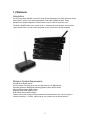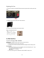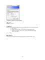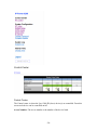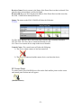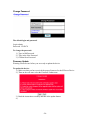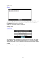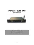
1
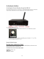
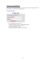
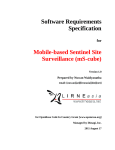
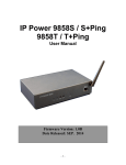
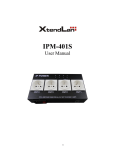
IP Power 9268 /
IP Power 9268SE
User Manual
IP Power 9268
IP Power 9268SE
Firmware Version: 1.3
Date Released: 10/21/2009
-1-
Warning: Any changes made to this equipment without permission may cause damages to the
device!
IMPORTANT NOTICE
1. IP Power 9268 / 9268SE was designed for indoor use, we carry no responsibility for possible
damages caused by outdoor use, especially in the rain.
2. Please use the power adapter provided by the dealer, we carry no responsibility for the
possible damage from using power adapters not .
4. Do not shake the IP Power 9268 / 9268SE in any fashion
5. Please contact the dealer If IP Power 9268 / 9268SE is not working properly.
Copyright © 2008 All rights reserved. No part of this publication may be reproduced,
stored in a retrieval system, or transmitted in any form or by any means, electronic,
mechanical, photocopying, recording or otherwise, without the prior written consent of us.
All trademarks and products mentioned in this document are the properties of us.
-2-
Table of Content
1.) WELCOME ...................................................................................................... 5 Introduction .................................................................................................................................................. 5 Minimum System Requirements ................................................................................................................. 5 2.) PRODUCT OVERVIEW ................................................................................... 6 Features ......................................................................................................................................................... 6 Specification .................................................................................................................................................. 6 Package Contents ......................................................................................................................................... 7 Package Contents ......................................................................................................................................... 7 3.) INTERFACE DESCRIPTION ........................................................................... 9 9268 -M (Master) .......................................................................................................................................... 9 9268 -PR (Power Receiver) ........................................................................................................................ 10 4.) SETTING UP THE IP POWER 9268 / 9268SE.............................................. 12 Step 1: Setting up the Hardware ............................................................................................................... 12 Step 2: Setting up the device with IP Edit ................................................................................................ 12 Step 3: Setting up the 9268 / 9268SE-PR RF settings .............................................................................. 13 Step 4: Accessing the device from outside the network ........................................................................... 15 5.) HARDWARE INTERFACE ............................................................................ 16 Controlling the Device Manually through the 9268 -M .......................................................................... 16 Reset to Default values ............................................................................................................................... 16 Replacing the Fuse...................................................................................................................................... 18 6.) WEB INTERFACE ......................................................................................... 18 Log In to IP Power 9268 / 9268SE............................................................................................................. 18 Logging In ............................................................................................................................................... 19 Main Screen ............................................................................................................................................. 19 -3-
Control Center ............................................................................................................................................ 20 Control Center ......................................................................................................................................... 20 RF Control Panel: .................................................................................................................................... 21 System Configuration ................................................................................................................................. 22 RF Setup .................................................................................................................................................. 22 System Setup ........................................................................................................................................... 23 DDNS Setup ............................................................................................................................................ 24 Email Setup.............................................................................................................................................. 25 Change Password ..................................................................................................................................... 26 Firmware Update ..................................................................................................................................... 26 System Log .................................................................................................................................................. 27 Change Time ............................................................................................................................................... 27 Logout .......................................................................................................................................................... 27 7.) FREQUENTLY ASKED QUESTIONS (F.A.Q) .............................................. 28 -4-
1.) Welcome
Introduction
The IP Power 9268 / 9268SE is a state of the art Power Distribution Unit (PDU) & Remote Power
Control (RPC) system. The various applications of the 9268 / 9268SE includes: Power
Management, System Integration, Remote Power Control in Remote locations, & etc.
The 9268 / 9268SE allows you to control up to 4 / 2 separate devices remotely via the internet
using a web browser, you can control the power to your devices from virtually anywhere.
Minimum System Requirements
CPU Minimum Requirements
CPU Processor: The same as or above a Intel Pentium III or AMD Athalon
Operating Systems: WINDOWS Operating Systems (IE5.0+SPI) & LINUX
Memory Requirements 64MB or More
Supports Direct Draw Graphics Card
RJ45 LAN & Internet HUB & Switch
Internet (For remote access) or Ethernet Network (Internal Network use) with some type of
Internet connection, (i.e. ADSL, Cable, Dial up or any other forms of Internet service)
-5-
2.) Product Overview
Features
1.
2.
3.
4.
5.
6.
7.
8.
9.
10.
11.
One Master Connects 4 / 2 Receiver devices
Each slave device can connect up to a distance of 30 - 50 Meters
Email Capabilities
Supports: TCP/IP, Http API, Web Server, SMTP Server, DDNS, Log file, CNT, XML
Customize the name of each device and each port of each device
Remote controller on Master device for local control
Base 64 Password Encryption
Log Capability
Bi-Directional safety control communication for device status retrieval.
CNT Technology: No Port Forwarding Needed in Router – Just Plug & Play
IP Service: Easily Find your device on the internet without having to remember
complicated IP’s
12. Compatible with IP Power Center Power Management Windows Software.
Specification
9268-M (Master)
1. Input DC: 5DC
2. Dimensions: 75 x 120 x 25 mm
3. Weight: 263.3 g
4. RF Frequency: 433/315 MHZ
9258-PR (Power Receiver)
1. Input Power Voltage 90-240 VAC
2. 4 Power Outlets
3. Dimensions: 115 x 260 x 45 mm
4. Weight: 923.4 g
5. RF Frequency: 433/315 MHZ
* For 220-250V, please use power cable that can support 10A current.
Max. Output current: (total of each four outlets) 10A, (each outlet) 6A.
* For 100-120V, please use power cable that can support 15A current.
Max. Output current: (total of each four outlets) 15A, (each outlet) 6A
-6-
9268 / 9268SE Package Contents
9268 Package Contents
1.) 9268 -M (Master) Unit x 1
2.) 12V 1A Power Adapter
2.) 9268- PR (Power
Receiver) Unit x 4
3.) Antenna Unit x 5
4pcs 9268-PR
2.) Installation CD
4.) RJ45 Cable x 1 (Optional)
5.) Input Power Cable
(Optional)
-7-
9268 SE Package Contents
1.) 9268 -M (Master) Unit x 1
2.) 12V 1A Power Adapter
2.) 9268- PR (Power
Receiver) Unit x 2
3.) Antenna Unit x 3
2pcs 9268-PR
2.) Installation CD
4.) RJ45 Cable x 1 (Optional)
5.) Input Power Cable
(Optional)
-8-
3.) Interface Description
9268 -M (Master)
Front View
1.) Device Selection: The PR Device Selection
2.) 9268-M Reset:
To reset to original manufacture settings, hold down the reset button with a pen or a pin for 7
seconds or more.
The Default Values of the IP Power 9268 / 9268SE are
Default IP Address: 192.168.1.192
Default Login: admin
Default Password: 12345678
3.) Power Controls:
Once a 9268 -PR (Slave) has been selected hit the 1, 2, 3, 4 buttons to active the outlets of the
9268-PR. When the power outlet is on the 9268 -M will light up the green LED.
4.) Ac Power:
The green LED will light up when the device is properly powered and plugged in
-9-
Rear View
1.) 9268 -M Network Jack RJ45:
Connect the 9268 / 9268SE-M to the Ethernet / internet though this jack
2.) 9268 –M Reset:
Use a DC 5V 1A Power Adaptor.
9268 / 9268SE-PR (Power Receiver)
Front View
- 10 -
1.) RS232 Com Port
The RS232 Com Port is currently used by the manufacturer for debugging purposes
2.) Output Ports
The green LED lights will light up with the output has been turned on
3.) Reset
The Reset button is used to setup the RF device. Please go to (RF Connection Setup) for more
instructions
4.) Link
The link will show if the IP Power 9268 -PR (Slave) is connected to the 9268 -M (Master) device
Rear View
1.) Output Ports
Connect the devices that need to be controlled in the Output Ports.
2.) Input Power
The Input Power allows the 9268 -PR to power up the devices.
3.) Surge Protector
In the case of a power surge, the fuse in located in the Surge protector.
4.) Power Switch
Power switch turns on or/off the IP Power 9268 -PR
- 11 -
4.) Setting up the IP Power 9268 / 9268SE
Setting up the IP Power 9268 / 9268SE:
Note:
For 220-250V, please use power cable that can support 10A current.
Max Output Current: (total of each four outlets) 10A, (each outlet) 6A.
For 100-120V, please use power cable that can support 15A current.
Max Output Current: (total of each four outlets) 15A, (each outlet) 6A
Step 1: Setting up the Hardware
1.) Connect the IP Power 9268 -M to a HUB or Router with a RJ45 network cable.
2.) Connect the HUB or Router to the internet (May through ADSL/XDSL
modem).
3.) Connect the power adapter to the IP Power 9268 / 9268SE-M (Master).
Step 2: Setting up the device with IP Edit
From the CD provided install IPEdit Search Tool. Please update IPEdit to the latest
version by hitting the Update button in IPEdit
- 12 -
1.) Once IPEdit is open the device will automatically appear in the local devices section.
Highlight the device and on the right side of IPedit the Fields will be populated with
default information
2.) Type in a Name for the device
3.) Type in the network gateway (I.E Router Gateway, Hub).
This information can be found in your network settings.
4.) Type in the IP Address of the device.
5.) Select a Port number other than 80 to avoid conflicts with other hardware
6.) Once all settings have been entered correctly, hit the submit button to save all
changes.
Step 3: Setting up the 9268 -PR RF settings
Once all the settings have been entered then it is time to setup the 9268 -PR (slave) boxes.
To setup the boxes it is recommended to have the box stay near the computer you will be using
to setup the device.
Follow the following steps:
1.) First connect the power cable to the 9268-PR (slave) and turn on the power.
2.) Then hit the reset button on the 9268 -PR to start the recognition process. The 9268 -PR
will start to make “Beeping sounds”
3.) Then Open IPEdit double click on your device in the local Area section. Or enter the IP
Address of your device into Internet Explorer.
4.) Login to the IP Power 9268 -M
- 13 -
The Default Values of the IP Power 9268 / 9268SE:
IP Address: 192.168.1.192
Login: admin
Password: 12345678
5.) After logging into the device Select the RF Setup link
6.) While the 9268-PR is still beeping hit the GetID button.
Example:
If you want the device to be in Receiver 1 Select GetID1
- 14 -
7.) Once the device has been setup click on RF control link to left of the page to check to
make sure the device has been connected.
Step 4: Accessing the device from outside the network
Note:
To access the device from outside of the network you must port forward, port triggering, the
routers that is being used to connect the device. Please refer to the routers manual since each
routers settings are setup differently.
For example our device above has the following information
IP Address: 192.168.100.122
Port: 8080
On the routers side you will need to port forward / port trigger this information so that it can be
accessed from outside the network.
- 15 -
5.) Hardware Interface
Controlling the Device Manually through the 9268 -M
The 9268-M allows the device to remotely be controlled through the internet. It also has a
remote feature which allows for local control of the 9268 -PR (slave) devices.
To Control the 9268 -PR devices:
1.) With Device Selection Knob and select the device you would like to control.
2.) Then press the Power Controls to control the power of outlets 1, 2, 3, or 4. The
LED will light up if the power is on.
Reset to Default values
Resetting Values to Manufacturer Default
To reset to original manufacture settings on the IP Power 9268-M (Master), hold down the reset
button with a pin or pen for 7 seconds or more.
The Default Values of the IP Power 9268 / 9268SE:
IP Address: 192.168.1.192
Login: admin
Password: 12345678
- 16 -
“Super User” Password Reset
In an even where the password cannot be recovered, the “super user” password reset can
be used (There is a space between super & user )
To reset the password:
1.) Go to the login page of the device
2.) Type in the words “super user” without the quotations.
(There is a space between super and user.)
3.) Click the Ok button to confirm.
4.) Then Unplug and then plug in the 9268-M device.
- 17 -
Replacing the Fuse
1.) The fuse is located on the 9268-PR (Slave) between the power switch and the power input
plugs.
2.) Carefully remove the fuse holder with a flat screwdriver.
3.) The fuse can be purchased at most electrical stores
Model: U/C GFE 10A 250V (PF)
6.) Web Interface
Log In to IP Power 9268 / 9268SE
Once the 9268 / 9268SE has been setup correctly, log into the device.
First Option
1.) Go to IPEdit find the device that is being used
2.) Double click on the device link and a IE window will appear with the loading screen
Second Option
1.) Open Internet Explorer type in the IP Address of the device followed by the “:” sign.
For example: http:192.168.122.188:9258
192.168.122.188 – IP Address
9268– Port
2.) Once you have typed in the address the 9268 / 9268SE is ready to use.
- 18 -
The default password for the 9268 / 9268SE
Login: admin
Password: 12345678
Logging In
After the device has been configured it is time to login to the device via the web interface.
3.) Open IPEdit
4.) Find the IP Power 9268 / 9268SE Device on the right hand side
5.) Double click on the IP Power 9268 / 9268SE and a Internet Explorer
window will appear
6.)
7.)
Main Screen
After the device is logged in the following page will be displayed on the screen.
- 19 -
Control Center
Control Center
The Control center is where the 3pcs 9268-PR (slave) device(s) are controlled. From this
screen each device can be controlled on/off.
Access Number: The access number is the number of the device listed
- 20 -
Receiver Name: Receiver name is the Name of the Power Receiver that is selected. If no
name has been selected then it will be left blank
Receiver ID: Receiver ID is the physical address of the Power Receiver that is used by
the 9268 / 9268SE-M to identify the device
Status: The status on the 9268 / 9268SE will show the following:
On: The 9268 -PR Slave device has been setup correctly and is currently detectable
Off: The 9268 –PR Slave device cannot be detected or is off
NA: There is no current device setup on that access Number
Control Center: The control center will show the following:
1.) The device cannot connect or has been turned off
2.) The device is connected and the master device can detect the device
RF Control Panel:
To control each of the 9268-PR Device click on the little satellite picture on the screen
and control panel for that unit will appear
’
(Satellite Picture)
- 21 -
(Control Panel)
From the control panel each power outlet for that device can be customized.
Hit the apply button
after the changes have been made.
To turn on or off the outlet select On or Off and then hit the apply button to activate the
command.
System Configuration
Configure the system configuration page is where the device will be setup.
RF Setup
To connect the 9268-M (Master) to the 9268 -PR (Slave) devices follow the following
directions:
Setup the 9268 -PR (Slave device)
1.) Hold the “reset” for the 9268 -PR for more than 5 seconds until you hear a
“beep” “beep” sound.
- 22 -
2.) Make sure there is no device already connected on the webpage of the 9268 -M
(Master). If a device is already in the Receiver area, hit the “clear button” to
remove the already configured device.
3.) Once the device has been cleared hit the “Get Id button” and the 9268 / 9268SE
will automatically detect the device.
4.) Once the device(s) has been setup, type in the receiver name and hit the apply
button to save the changes that were made.
System Setup
The system setup section is where changes to the networking settings are made. In this
section you will find the following information.
IP Address: IP Address of the IP Power 9268 / 9268SE
Subnet Mask: Subnet mask of the IP Power 9268 / 9268SE
Default Gateway: Default gateway information of the IP Power 9268 / 9268SE
DNS: DNS settings of the IP Power 9268 / 9268SE
DHCP Client: Enable or Disable Automatic DHCP
Beeper: Turns off the beeper sound of the IP Power 9268 / 9268SE
Http Command Verification: Turns on / off the Http: commands of the device.
Device Name: Enter name for the device.
Release Version: Displays the current Firmware Version
- 23 -
DDNS Setup
DDNS setup allows the IP Power 9268 / 9268SE to be used on DDNS. A DDNS account
must be applied for
The following information will need to be inputed:
DDNS Server IP: This is where you Enter the DDNS Server IP
Your Domain: Enter the Domain Server from DDNS
DDNS UserName: Enter the Username from DDNS
DDNS Password: Enter the password that is used on DDNS
Enable DDNS: Select True if DDNS will be enabled
Proxy Enable: Select True if Proxy will be enabled
Proxy IP: Enter the proxy IP For DDNS here
Proxy Port: Enter the proxy port for DDNS here
Save: The save button saves the settings that have been selected
Update: Press the update button to update the settings on DYNDNS.
- 24 -
Email Setup
The Email function of the IP Power 9268 / 9268SE allows the device to notify the user
when changes have been made, power outlets are turned on or off, or any modification of
the fields.
Smtp Server: Type in the server address of the Email provider
Smtp Port: Type in the port of the SMTP email server
Pop3 Server: Type in the Pop 3 Incoming mail server
User Name: Type in the user name for the email address
Password: Type in the password for the Email Address
Sender: Type in the Sender E-mail
Receiver 1: Type in the Receiving address
Receiver 2: Type in the Receiving address
Receiver 3: Type in the Receiving address
Subject: Email subject Line
Mail body: Mail body
Save: The Save button will save the current set settings
Send: The Send command will send a test email testing the settings.
- 25 -
Change Password
The default login and password:
Login: admin
Password: 12345678
To change the password:
1.) Type in Old Password
2.) Type in the New Password
3.) Confirm New Password
Firmware Update
Warning: Please be sure before you are ready to update the device.
To update the device:
1.) Make sure that you have received the proper firmware for the IP Power Device
2.) Then on the web page select the Firmware Update page
3.) Read the instructions carefully and then it the update button.
4.)
- 26 -
System Log
The System Log keeps track of the movements of the IP Power 9268 / 9268SE. From this
page, information on the device, which ports are being will be collected and gathered.
Refresh: Refresh will refresh the current log
Clear: Clear will clear the current log information
Change Time
The change time feature allows the device to always have the correct time / date. In this
settings, the Date / Time can either be manually entered. Or at NTP Server IP Address
can be provided and the device will automatically keep track of the current time and date
Logout
Logout allows the user to logout of the current system.
- 27 -
7.) Frequently Asked Questions (F.A.Q)
Q1: How do I reset the device back to manufacturer default values?
Ans: In the front panel of the 9268 -M, there is a reset feature that will reset the device back to
manufacturer default settings. Take a pen or small pin, then press and hold for about 10-15
seconds. Once you hear a single “beep” sound the device will be reset back to manufacturer
default
Q2: How come I cannot connect to my device from an outside network?
Ans: To use the device outside of LAN (Local Area Network. If a router is present you will have to
port forward the Local IP Address of the 9268 / 9268SE so that it could be reached by the outside
world. Please refer to the manual on how to accomplish this task.
- 28 -