1
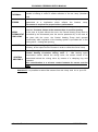
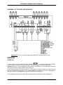
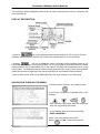
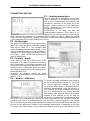
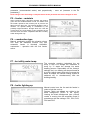
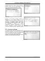
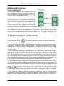
WEATHER-BASED CONTROLLER Economic PREMIUM User’s Manual © RecalArt Electronic (DD20091029) ECONOMIC PREMIUM USER’S MANUAL CONTENT PREFACE ................................................................................................................................................. 4 ASSEMBLY .......................................................................................................................................... 5 CONNECTION ...................................................................................................................................... 5 PRECAUTIONS .................................................................................................................................... 6 WORN EQUIPMENT PROCEEDINGS ............................................................................................... 7 GENERAL INFORMATION ................................................................................................................. 7 UNIT DESCRIPTION ........................................................................................................................... 8 OUTPUTS DESCRIPTION ................................................................................................................ 9 GAUGE INPUTS DESCRIPTION ..................................................................................................... 9 ASSEMBLY OF DEVICES AND SENSORS ..................................................................................... 11 SERVICE ................................................................................................................................................ 11 START-UP ........................................................................................................................................... 11 DISPLAY DESCRIPTION .................................................................................................................. 12 NAVIGATION THROUGH THE MENU ........................................................................................... 12 PARAMETERS SETTING .................................................................................................................. 13 P1 – heating temperature ................................................................................................................. 13 P2 - heating type .............................................................................................................................. 13 P3 – feeders - break ......................................................................................................................... 13 P4 - blower – efficiency................................................................................................................... 13 P5 – feeder – maintain ..................................................................................................................... 14 P6 – combustion type ....................................................................................................................... 14 P7 - hot utility water temp. ............................................................................................................... 14 P8 – boiler lighting up ..................................................................................................................... 14 P9 - heating SUMMER/WINTER ..................................................................................................... 15 P10 - weather characteristics .......................................................................................................... 15 P11- Service options......................................................................................................................... 15 P12 - Controller test......................................................................................................................... 15 P13 - Factory's settings .................................................................................................................... 16 ADDITIONAL FUNCTIONS – PID .................................................................................................... 17 ADDITIONAL EQUIPMENT .............................................................................................................. 18 ROOM THERMOSTAT ...................................................................................................................... 18 ALARM STATES AND PROTECTIONS ........................................................................................... 18 SERVICE SETTINGS AVAILABLE FOR THE AUTHORIZED SERVICE CENTER ONLY .. 19 P1 – Boiler’s minimal temp. ............................................................................................................. 19 P2 – Maximal boiler’s temp. ............................................................................................................ 19 P3 – critical boiler’s temp. ............................................................................................................... 19 P4 – boiler’s protective temp. (the function operates with the servo only) ...................................... 19 P%- Ling other – feeder ................................................................................................................... 19 P6 – Blower – lighting up ................................................................................................................ 19 P7 – Alarm temperature of the feeder .............................................................................................. 19 P8 - Central Heating pump’s operation ........................................................................................... 19 P9 H.U.W priority on / off ................................................................................................................ 19 P10 – H.U.W priority – time ............................................................................................................ 19 P11 – HUW additional boiler’s temp. .............................................................................................. 19 P12 – No fuel – switch on/off ........................................................................................................... 20 P13 – No fuel - time.......................................................................................................................... 20 RecalArt Electronic 2 OCTOBER 2009 ECONOMIC PREMIUM USER’S MANUAL P14 – Boiler cleaning....................................................................................................................... 20 P15 – PID(on/off) ............................................................................................................................. 20 P16 – Thermostat – decrease (the function operates with the servo only)....................................... 20 P17 - Automaton SUMMER-WINTER ............................................................................................ 20 P18 – Mixing valves additional boiler’s temp.................................................................................. 20 P19 – Main Mixing Valve................................................................................................................. 20 P20 – Three Way Mixing Valve........................................................................................................ 20 P21 – BIOMASS – lighting up.......................................................................................................... 21 TECHNICAL DATA ............................................................................................................................. 22 TERMS AND CONDITIONS REGARDING GUARANTEE AND COMPLAINTS ..................... 23 GENERAL PRINCIPLES FOR THE GUARANTEE.......................................................................... 23 EXECUTION OF THE GUARANTEE ......................................................................................................... 24 GUARANTEE EXCLUSIONS .................................................................................................................... 24 GUARANTEE CARD ............................................................................................................................ 25 RecalArt Electronic 3 OCTOBER 2009 ECONOMIC PREMIUM USER’S MANUAL Preface User’s manual is designed for all persons who will deal with connection, assembly, providing service and routine maintenance for controllers from ECONOMIC 3000 series. In the manual we contained descriptions of systems, instruments, functions and operating procedures. This manual must be kept in a workplace when a regulator is serviced; always observe included in the manual information. Attention When a failure occurs or there is no additional instruments as well as to receive additional information, please, contact your representative or RECALART ELECTRONIC dealer. ECONOMIC 3000 controllers are designed to be assembled in control boxes or similar ones in a way preventing from contact with electric wiring terminals. Do not remove a regulator from its housing. Never place your hand or any other conductive organ in housing. It can cause a heavy damage to body or death as a result of electric shock. To avoid damaging connected units, appliances or the ECONOMIC 3000 series controllers themselves as a consequence of the product’s failure, take all precautions before use, such as assembly of a fusible cut-out, appliances protecting from overheating etc. Should an accident occur as a result of exploitation of a product without taking such precautions into accounts, the guarantee is invalid. To turn power supply off, install a breaker switch in external circuit of the controller. The breaker switch must be assembled in a way it adheres to the instrument in a position enabling easy service; it must be equipped with a sign that its function is turning power supply off. Use switch meeting the IEC947 norms. Fusible cut-out: Since the instrument is not equipped with an in-built fusible cut-out, you can not forget assembling of the fuse in power circuit after connection to a phase terminal. The fusible cut-out should be placed between the breaker switch and the instrument and assembled on the ‘L’ side of the phase terminal. Rated values / characteristics of the fusible cut-out: 250 VAC 3A quick. Use a fusible cut-out meeting the IEC 127 norms. Voltage / current values of load for output terminal and alarm terminal should be within nominal values of the range. In other case, increasing temperature will decrease the regulator's life cycle and cause problems related to the device work. Other voltage / current than specified in the specification of the input can not be connected with the input terminal. It can result in a short life cycle of the unit and cause problems related to the unit’s work. In case of voltage input or current input the input terminal should be connected with a unit which meets requirements of IEC1010 norm. RecalArt Electronic 4 OCTOBER 2009 ECONOMIC PREMIUM USER’S MANUAL The unit is equipped with ventilation holes enabling heat abstraction. Take care for holes, do not allow any unauthorized metal elements or other elements in as they can cause the unit’s failure or become a reason for fire. Prevent the ventilation hole from being blocked or dirty. Temperature increase or insulation failure can cause short life cycle of the unit and consequent failures as well as it can be a reason for fire. Information regarding distance between assembled controllers in a control box is given in the chapter titled: ‘External dimensions and panel cutting’ in documentation for maintenance. It should be underlined that repeatable tests of voltage tolerances, interferences or over voltage can result in worsening of the unit’s work. A user mustn’t implement any modifications of the product or exploit it in a prohibited way. ASSEMBLY The regulator mustn't be exploited in the below described localizations: In environment of easily-flammable gases, gases which cause corrosion, oil mist, dust potentially impairing condition of electric insulation. In atmosphere of temperatures below 0°C or exceeding 55°C and relative humidity exceeding 90%RH or below saturation point. In environment characterized with large level of vibrations and shocks In localization endangered by large electromagnetic disturbances. In localization endangered by direct sunlight. In environment of height 2000m above the sea level. Outdoor. Selection of such localizations can cause incorrect work of the unit, its damage or it can be a reason for fire. Warning To be safe do not remove a regulator from its housing. If a one needs to remove the regulator from its housing in order to replace or repair it, he / she should ask a representative or a dealer point to do this. CONNECTION A person who is supposed to install the main unit should be relevantly qualified to assemble electrical devices. When connecting the regulator give special consideration to the following circumstances: Hazard All assembly works related to assembly or disassembly of electric wiring can be performed only when sources of the power supply were previously cut-off. Do not touch terminals or other live elements of the unit. All made connections must be accordant with the system’s assembly electric scheme and domestic or local regulations pertaining to electric connections. 1. When assembling the electric system of the regulator observe recommendations contained in this manual. RecalArt Electronic 5 OCTOBER 2009 ECONOMIC PREMIUM USER’S MANUAL 2. Connections made of copper wire should be adjusted to work in temperature not exceeding +75°C. 3. In case of a thermocouple’s input use a compensating lead relevant to a type of the selected thermocouple. 4. Input signal lead mustn’t be localized in the same duct as the power cable. 5. Utilization of relevant lead (spiral) for the input signals is efficient and protects from disturbances resulting from electromagnetic induction. 6. To provide power to the regulator use cable of the same or higher parameters than parameters of a lead insulated by vinyl 600V of 1 mm2 cross-section or larger. 7. Tight terminals’ screws with 1,0 Nm torque. 8. If the unit turns out to be prone to power disturbances use an anti-disturbances filter in order to prevent the unit from incorrect work. The anti-disturbances filter assemble on grounded panel and provide possibly the shortest connections of leads between the antidisturbances filter filter’s output and terminals of the regulator’s power cable. PRECAUTIONS Before first use of the main unit, study this manual carefully. Keep this manual and refer to it in case you work with the unit in the future. Keep all regulations and warnings contained in this manual. Make sure the unit is not damaged in any way. Should any doubts occur, do not exploit the unit and contact your provider. Should any doubts regarding safe exploitation of the unit occur, do not exploit the unit and contact your provider. Give special attention to all warning signs placed on the housing and the unit’s package. Use the unit for intended use only. This unit is not a toy; do not let your children play with it. Under no circumstances do not allow your children play with any part of the unit’s package. Prevent access to small components, e.g. assemble screws, pins for children. These components may be a part of delivered unit and a child can strangle in case of swallowing. Do not implement any electrical or mechanical modifications of the unit. Such modifications can cause incorrect work of the unit, incompliant to norms, and negatively affect the unit’s work. Do not insert through gaps (e.g. ventilation gaps) any objectives inside the unit as it can cause short-circuit, electrocution, fire or damage of the unit. Do not let water, humidity and dust get inside the unit as it can cause short-circuit, electrocution, fire or damage of the unit. Provide correct ventilation of the unit, do not cover or screen ventilation holes, provide the unit with a free air flow around. The unit must be assembled indoor if it is not adjusted to work outdoor. Prevent the unit from any shocks and vibrations. When the unit is being connected, make sure that parameters of the power line are relevant in scope of the unit working parameters. To avoid electric shock connect the unit to a socked with a grounded pin. Grounding of the socket must be correctly prepared by a certified electrician. When the unit is being connected make sure it will not result in the electric circuit overloading. Prevent connection of the unit to a one circuit together with engines and other units causing impulse disturbances (e.g. washing machines, fridges, ...) Before any leads and peripheral units are connected to the main unit, unconditionally turn off the power supply. RecalArt Electronic 6 OCTOBER 2009 ECONOMIC PREMIUM USER’S MANUAL In order to absolutely disconnect the unit from the power supply, pull out the plug from power supply socket, especially when it is not supposed to work for a long term. Protect the power supply cable from damages, it should be leaded in a way that nobody walks on it and no objects stand on the cable. All made connections must be accordant with the electric scheme of the system assemble and domestic or local regulations pertaining to electric connections. No components in this unit can be replaced by a user himself / herself. All maintenance activities, apart from cleaning, fuse replacement (unit must be disconnected from power supply), or functions setting should be made by an authorized service only. Before any maintenance works, unconditionally disconnect the unit from the power supply. To clean the housing of the unit do not use petrol, solvents or other chemical agents as they can damage the housing. Use of soft wipe is recommended. If the power supply cable is damaged, unit mustn’t be use unconditionally. Damaged cable must be replaced by a service with a new one of the same parameters as the original cable. WORN EQUIPMENT PROCEEDINGS The electronic unit was made of materials which can be recycled partially. For this reason, when it has been worn it must be transported to electric and electronic units recycling point or transported to its manufacturer. The unit can not be disposed together with other ‘household’ discards. EXPLOITATION SAFETY This manual must be given to a final user of the unit. GENERAL INFORMATION PREFACE Economic 3000 boiler’s work regulator is a modern micro-processor unit which controls over either, the boiler’s work, central heating system in ‘weather mode’ and hot utility water as well. The unit controls over quantity of fed fuel due to cyclic work of feeder’s engine and quantity of air delivered for process of combustion. Due to utilization of semi-conducting systems capacity of blower is regulated smoothly; additionally, reliability of the system controlling over the feeder’s engine was enhanced. Weather-based controlling provides the best heat comfort as the heat temperature is regulated by external temperature function. Regulation process is made due to mixing valve’s actuator. RecalArt Electronic 7 OCTOBER 2009 ECONOMIC PREMIUM USER’S MANUAL Use of sensor for temperature of water returning from the Central Heating system and regulation of this temperature by means of the mixing valve decreases fumes’ condensation in a boiler which reduces corrosion significantly. Due to advanced algorithm of work and possibility of regulation of many parameters, the system can be flexibly adjusted for requirements of the heating system. The controller is equipped with TEST function. This function is available in MENU and enables control over correctness of electric connections and temperature sensors. It is possible to check efficiency of executive units (pumps, blower, feeder, mixing valve’s actuator) before a boiler is launched. A graphic display provides very simple service of the unit. UNIT DESCRIPTION Two-module unit consists of the following elements: operator’s panel, visible for a user component of the main unit together with keyboard and graphic display. The panel is assembled in front part of a boiler. executive module, which must be assembled on DIN rail in switchgear or other guard. To the module there are connected all sensors, units and the operator’s panel. tape connecting the operator’s panel to the executive module To ensure essential work of the main unit, connect sensors necessary for the boiler's work to the executive module. feeder’s temperature sensor [FEEDER] boiler’s feeding temperature sensor [BOILER FEEDING] To launch other functions of the controller, connect relevant sensors to the executive module: hot utility water temperature sensor [C.W.U] - if a one wants to use hot water heat agent temperature sensor behind the mixer [C.O.] - if a one wants to control over mixing valve sensor of returning heat agent’s temperature [Boiler’s return] – if a one wants to protect the boiler additionally from corrosion (the function works only when mixing valve is connected) external temperature sensor [External] – when a one wants to use ‘weather-based function' (no external sensor connection will result in incorrect work of the weather-based function). Room thermostat, or room regulator of type, e.g. EUROSTER [Room thermostat] – if a one wants a room temperature to affect heat parameters RecalArt Electronic 8 OCTOBER 2009 ECONOMIC PREMIUM USER’S MANUAL OUTPUTS DESCRIPTION DESCRIPTION DEVICE Central Heating Circulation Pump - max 1,2(0,6)A 230V~ ATTENTION. In the case of a plant without servo, the Central Heating Pump is started after minimal temp. has been reached – the service parameter P1. In the Central Heating pump case of a plant with the servo, the Central Heating Pump works continuously. In the case of a plant with the room thermostat and without the servo, the Central Heating Pump work is controlled by the thermostat (see: the service parameter 11). Undependably of the operational mode, the Central Heating Pump is started after T. max + Critical t. (service P2 + P3) have been exceeded. Hot Utility Water Pump Hot Utility Water Storage Bin Pump – max. 1,2 (0,6) A 230V~ The h.u.w pump is started in the case there is a need for the h.u.w. Undependably of the operational mode, the Central Heating Pump is started after T. max + Critical t. (service P2 + P3) have been exceeded. Mix. valve closed 1 Mix. valve open Mix. valve closed 2 Mix. valve open 2 FEEDER Mix. Valve servo 1 (closing) – max. 1,2 (0,6) A 230V~ BLOWER Blower engine – max. 1,2(0,6)A 230V~ HEATER Heater – max. 4(2)A 230V~ Mix. Valve servo 1 (opening) – max. 1,2(0,6)A 230V~ Mix. Valve servo 2 (closing) – max. 1,2 (0,6) A 230V~ Mix. Valve servo 2 (opening) – max. 1,2(0,6)A 230V~ Fuel feeder screw engine – max. 1,2(0,6)A 230V~ GAUGE INPUTS DESCRIPTION Description BOILER – POWER SUPPLY BOILER RETURN HOT UTILITY WATER CENTRAL HEATING 1 Sensor Description Gauge input of the boiler’s temperature, the sensor is assembled on the boiler’s gauge hole. The sensor is required for the proper boiler’s performance. Temperature sensor of the heating agent on the return from the heating plant; the sensor needs to be assembled on the return pipe at the boiler or in a special gauge hole of the boiler or pipe. Give consideration to a relevant contact between the sensor and the pipe!!! Gauge input of the hot utility water sensor; the sensor is assembled in the gauge hole of the h.u.w exchanger. Assemble only in the case of assembled servo on the Central Heating circulation mixing valve 1 – the heating agent temperature sensor behind the mixing valve; the sensor needs to be assembled behind the mixing valve by means of a clamping ring and insulated. Give consideration to a relevant contact between the sensor and the pipe. RecalArt Electronic 9 OCTOBER 2009 ECONOMIC PREMIUM USER’S MANUAL EXTERNAL External temp. sensor gauge input. The sensor needs to be assembled outside a building in order to enable reflection of the ext. temp. (Northern wall). FEEDER Fuel feeder’s temperature sensor gauge hole; the sensor needs to be assembled at a localization which reflects the feeder's temp. The sensor is required for proper boiler’s performance. Room thermostat’s input. The room controller (with closing contacts) must be attached. Contacts obtuse at the moment there is need for heating. ROOM In the case of a plant without the servo, the Central Heating Pump work is THERMOSTAT controlled by the thermostat (see: the service parameter 8). In the case of POKOJOWY the plant with the servo, the Central Heating Pump shall operate continuously while regulation of the heating system is provided due to the mixing valve – closing and opening. FUMES Fumes’ temp. sensor gauge input. The sensor needs to be assembled in a chimney, at the output from the furnace in order to reflect the fumes’ temp. CENTRAL HEATING 2 Assemble only in the case of (previously) assembled servo on the Central Heating circulation mixing valve. 2 – the heating agent temperature sensor behind the mixing valve; the sensor needs to be assembled behind the mixing valve by means of a clamping ring and insulated. Give consideration to a relevant contact between the sensor and the pipe. Attention!!! It is possible to extend the sensors from ext. temp. and h.u.w. up to 30 meters. RecalArt Electronic 10 OCTOBER 2009 ECONOMIC PREMIUM USER’S MANUAL ASSEMBLY OF DEVICES AND SENSORS Attention!!! Do not connect the protective cable (PE) and the zero one (N). SERVICE START-UP To start the device one needs to push the button „ ” ; in order to switch the controller off one needs to repeat the activity, however, the button needs to be held 5 seconds. Attention!!! When nothing appears on the display, the device is in the stand by mode and still under the power supply (green diode blinking). In the case the boiler is not to be used for a long period of time or when one plans carrying out some maintenance activities, it is recommended to switch the unit off by unplugging it. When the device is unplugged the controller memorizes the settings. On the display (main screen) valid state of performance of particular units is displayed. RecalArt Electronic 11 OCTOBER 2009 ECONOMIC PREMIUM USER’S MANUAL The animation being displayed means that the output controlling the device operation has been switched on. DISPLAY DESCRIPTION - symbols will not be displayed when the parameter no. 10 is set into 0 value. (weather characteristics switched off) or when the external sensor is not connected. - symbols will not be displayed when a relevant central heating sensor is not connected (accordingly, for the mixing valve 1 or 2). One needs to remember that the Central Heating sensor can be assembled only in the case of the plant with assembled servo on the mixing valve. The downward arrow means closing process of the mixing valve while upwards means the process of opening of the valve (total flow into the Central Heating system). - boiler’s return temp. shall not be displayed when the return sensor is not connected. NAVIGATION THROUGH THE MENU in order to enter the menu one needs to push in the menu navigation is possible due to the buttons: Data record is performed after the menu has been left, by pushing the button on the display there occurs the text string: ‘SAVE CHANGES’? select ‘yes’ and confirm pushing the button or „NO” to cancel the record. RecalArt Electronic 12 OCTOBER 2009 ECONOMIC PREMIUM USER’S MANUAL PARAMETERS SETTING P1 – heating temperature The set temp. will be maintained on the Cent. Heat. 1 circulation. In the case the mixing valve with a drive is assembled, the controller will increase in the temp. at the boiler by a few degrees (setting carried out in the authorized center – parameter no. 18) in order to enhance the valve’s performance. ATTENTION: In the case one sets the weather-based operation (P10) there is no opportunity for manual setting of the heating temp. and the P01 parameter is unavailable (AUTO mode). In order to enable the manual control over the boiler's temp. (heating) one needs to switch the weather-based operation off - in the parameter P10 (set the heating curve into 0). P2 - heating type The parameter needs to be set up upon the fuel used, next, select the boiler of relevant capacity from the list (LING 15…). The controller shall set the furnace parameters automatically. In the case of problems related to a fuel combustion, instead of the boiler type one needs to select the setting – LING OTHER and manually set the fuel feeding time. P3 – feeders - break In the case the ash pit is filled in with under burnt coal, it is a sign one needs to increase in the P3 parameter (or the blower efficiency P4). In the case of a long-period operation it is clear, that the coal is combusted 'lower and lower', one needs to decrease in the P3 setting (or the blower efficiency P4). Attention!! all changes should be slight, correction of parameters is recommended to be within 5 – 10 %. P4 - blower – efficiency To achieve a proper combustion one needs to provide a relevant amount of the air. Too much air causes significant increase in the coal consumption and results in decreased boiler's efficiency. Nevertheless, when the amount of air is reduced, the coal is combusted too slowly and as a consequence, the furnace provides less heating than potential values. A common mistake is that settings of the P3 and P4 parameters are adjusted in such manner, that the coal is well combusted (no under burnt coal in the ash) but the controller bocks the operation from time to time displaying the error ‘NO FUEL' (when the coal is in the storage bin). It means that the settings are adjusted correctly but the boiler’s efficiency has been set too low (too low efficiency in relation to the building's requirements, in particular, in the case of the ext. temp. below zero). In such case one needs to provide more coal (shorten the P3 RecalArt Electronic 13 OCTOBER 2009 ECONOMIC PREMIUM USER’S MANUAL parameter (recommended action) and proportionally - more air (increase in the P4 parameter)). Each change in the P4 setting is complete when the P3 parameter has been changed as well. P5 – feeder – maintain After a required temp. has been reached, the furnace goes into the sustain/maintain mode, the blower and the feeder operate a few minutes just to prevent the flame from the burnt out. The interval duration is set in minutes. An optimal setting is constituted by the possibly longest duration, through which the coal will not be burnt out. Such setting is very significant in the summer when the boiler cooperates with the hot utility water storage bin only. P6 – combustion type Manual combustion means the situation where one uses the additional furnace only (the automatic feeder is blocked) Automatic combustion – operation with the fuel feeder active. P7 - hot utility water temp. The controller sustains (maintains) the set temp. in the h.u.w storage bin. Decrease in temp. by °C starts the storage bin water heating process. Dependably on the factory’s settings, the h.u.w heating can be performed as a priority (which means that at the moment the water is heated, the central heating system is switched off) or simultaneously with the building heating. P8 – boiler lighting up Manual control over the fan and the feeder in order to light the coal up. Devices, which are started, are visible in the black background (STOP in the figure). Leaving the black background (see: picture) results in moving into the automatic mode in accordance with the settings: PO1, PO2, PO3, PO4 and PO5. RecalArt Electronic 14 OCTOBER 2009 ECONOMIC PREMIUM USER’S MANUAL P9 - heating SUMMER/WINTER The P9 parameter specifies the way the controller operates. A user has three opportunities described herein. SUMMER – the controller heats the hot utility water up. CH pump. ( CH) Does not operate while the mixing valve (if assembled) is closed WINTER – The central heating operates and the hot utility water is provided. CH setting and HUW setting is possible due to relevant parameters. The controller stays in this operation schedule/mode until manual change into other one (e.g. SUMMER schedule) AUTO – The controller, on the basis of the external temp, automatically selects the SUMMER or WINTER mode (temp. of automatic switch between the Summer - Winter, Winter - Summer, Service parameter P17). P10 - weather characteristics Attention: Setting no. 0 – switches the weatherbased operation off – it is possible to set the heating temp. manually – in P1. After assembly of the external sensor one can start up the automatic adjustment of the heating temp. - so called 'weather-based operation'. Selection of a number of the characteristics for a building should be carried out upon the table below , with consideration given to the heating system type. Approximate settings table: After pushing the button one may set the temp. required in a room (Troom:24C). The controller shall carry out additional correction of the weather characteristic on such basis. It aims to provide a stable internal temp. throughout the entire heating season. P11- Service options Advanced controller’s parameters available after a technician's code has been entered. P12 - Controller test The controller’s test enables checking all inputs and outputs. It is possible to read all values of temperatures measured by the sensors – which enables control over correctness of the connections and sensor localizations. RecalArt Electronic 15 OCTOBER 2009 ECONOMIC PREMIUM USER’S MANUAL Switching particular contacts of the controller on enables control over the correctness of the device connections (pump, blower, feeder). Number of the device software version is displayed on the starting display of the controller. This information may be substantial in the case of technical support and when contacting an authorized service center. Since the technology is subject of a regular development process, enhancement of the devices constitutes a natural process. Also controller’s software has been upgraded regularly. P13 - Factory's settings All settings deletion and their replacement with the factory’s settings. The function may be used when the controller has been de-regulated and control over the boiler has been disabled. Attention: The function shall change the settings entered by an authorized center as well. RecalArt Electronic 16 OCTOBER 2009 ECONOMIC PREMIUM USER’S MANUAL ADDITIONAL FUNCTIONS – PID In the service options it is possible to switch the additional function on, which uses the PID regulation principles. After its activation the boiler’s power is automatically adjusted to the current need for heating. The boiler combusts the fuel more efficiently and emits less amount of contamination. Consequently, it does not require so frequent cleaning as in the case of the traditional operation. To use advantages of such control in an effective manner, it is required to set up a relevant power of the blower and the feeder’s interval duration. Such settings must be carried out for each level of the power, at which the boiler's furnace can operate. In the controller ECONOMIC PREMIUM there are provided 3 power levels at which the boiler may operate. To do it, one disposes with 2 parameters: 3-PID operation and 4-PID Parameters. Setting process of the controller is started by setting – in the PID operation parameter – the option Course I. The boiler shall operate with parameters for the course 1. Than, in the menu – PID parameters one sets parameters for the course 1 only, which means: mainten.time.courseI vent.power.courseI One needs to set up the fuel feeding duration and the fan’s efficiency for the course 1, in order to obtain the optimal fuel combustion. One needs to remember that the power assigned to the course 1 should be the least one. The best recommended option is to ensure, that the boiler, when operating at the course 1 provides at most 50% of its rated capacity. Process of correct setting of the combustion requires the boiler to operate several hours at least, at the same course, as well as correction of a few parameters. After a good combustion level has been achieved for the course 1, one sets up the COURSE 2 and repeats the parameters setting procedure: fuel feeding duration course II and fan’s efficiency course II. Also in this case one needs several hours of the boiler's operation at the course II. Approximate power at the course II should amount to approx. 75% of the boiler's rated capacity. The same procedure is required for the course III, to obtain 100% of the boiler's rated capacity. The general tendency is as it follows: Feed.t.course I < Feed.t.course II < Feed.t.course III Fan.effic.course I < Fan.effic.course II < Fan.effic.course III Now, one can switch the AUTO operation on, which completes the PID function settings. RecalArt Electronic 17 OCTOBER 2009 ECONOMIC PREMIUM USER’S MANUAL Additional Equipment ROOM THERMOSTAT The Economic PREMIUM can cooperate with any room temperature controller of closing contacts. A short circuit reduces the central heating temp. (the value set up by the authorized center). In the case of a plant without the servo, the Central Heating Pump work is controlled by the thermostat (see: the service parameter 8). In the case of the plant with the servo, the Central Heating Pump shall operate continuously while regulation of the heating system is provided due to the mixing valve – closing and opening. The THERMOSTAT should be assembled in a localization, which represents the general temp. in an apartment, at the 1,5 – 2 m above the floor. One must not assemble the device near heat sources (e.g. TV, heaters, sun lights) or in localizations exposed to draughts, since it will affect the system’s performance. ALARM STATES AND PROTECTIONS The controller uses the red diode to signalize that an alarm situation has occurred. After pushing the button „ ” information regarding the type of the alarm is displayed. The controller signalizes the following alarm states: - boiler overheating: the alarm is signalized when the boiler’s temp. exceeds the ‘boiler’s alarm temp.’, which is set in the ‘Service Options’. The action carried out in such case is switching the circulation pumps on, undependably on the operation mode (or servo opening) and switching the feeder and blower on, till the boiler’s temp. decreases to the value below the alarm temp. - feeder overheating; the alarm is signalized when the feeder’s temp. exceeds the ‘feeder’s alarm temp.’, which is set in the ‘Service Options’. The action carried out in such case is switching the feeder’s engine on (5 minutes) in order to remove the heat from the feeding pipe. Than, the controller waits (up to 5 minutes) for decrease in the feeder’s temp. In the case within ten minutes the feeder's temp. did not decrease to the value below the feeder’s alarm temp. the controller goes into the STOP statute and stops the boiler’s operation. The service of this function may be terminated when the feeder's temp. has decreased. - no flame/fuel; The alarm is signalized in the case of the lack of fuel or a flame in the burner. The most frequent reason for displayed alarm there is too low power of the burner set up on the controller by the service technician or user, or too low boiler’s efficiency adjusted to the plant. Such situation may happen in the case of a newly-built building, where a need for heating is larger because of wet plasters and internal walls as well as other building processes inside it. ATTENTION!!! After an alarm has occurred one needs to specify the reason for the alarm state and remove it. - ZTK protection (Boiler’s Thermal Protection) independent on the micro-processor performance. In the case when the boiler’s temperature exceeds 95°C an independent thermal breaker will operate, which switches the blower’s power supply off. A fuse will reswitch the power supply on when the boiler’s temp. decreases below 60°C. RecalArt Electronic 18 OCTOBER 2009 ECONOMIC PREMIUM USER’S MANUAL Service settings available for the authorized service center only P1 – Boiler’s minimal temp. It reduces on the minimal value of temp. set up, which protects the boiler from fumes condensation. The function also provides higher temporary temp. of the boiler. After the minimal temp. of the boiler has been reached, it is maintained on the same level despite the decrease in the need for the heat - the boiler maintains this value automatically. P2 – Maximal boiler’s temp. Reduction on the boiler’s maximal temp. protects from exceeding the max. temp. and the thermal fuses’ operation (ZTK). P3 – critical boiler’s temp. When the boiler exceeds the temperature constituted by a sum consisting of P2+P3 it results in protective measures, such as immediate de-pumping of hot water from the boiler- all pumps in the plant are switched on and the Central Heating mixing Valve 1 opening as well as stopping the fan and the feeder. P4 – boiler’s protective temp. (the function operates with the servo only) The parameter is tightly connected with the boiler’s sensor assembled on the return. When the temp. is lower at this point than the set value, the controller gradually closes the mixing valve. Such control simplifies the plant start up with large amount of the water. P%- Ling other – feeder Adjustment of the table of the feeder’s parameters – maintenance – fuel replenishment P6 – Blower – lighting up It sets the blowing power, which should not extinguish the flame during the lighting up. P7 – Alarm temperature of the feeder Exceeding the set up previously temperature by the feeder’s sensor shall start up the protective function. Emergency heat outburst should lead to the decrease in the temp. and enable further operation. In the case the reduction of the temp. measured by the feeder’s sensor is impossible, the controller shall stop the boiler’s operation. P8 - Central Heating pump’s operation It specifies the way of the control over the central heating pump where to the controller there is connected the room thermostat and the afore-mentioned thermostat has closed the contacts (the temp. in the room has been exceeded). 3 options to be selected: 0. Pump blockade 1. Pump blockade within 8 minutes, 2 minute operation and repeated 8 minute blockade etc. 2. Pump blockade within 6 minutes, 4 minute operation and repeated 6 minute blockade etc. P9 H.U.W priority on / off It switches the priority on/off P10 – H.U.W priority – time It switches the priority on after a time set up. During the next water heating the priority shall be active again until the time of loading the h.u.w exchanger has exceeded the parameter no. 10. P11 – HUW additional boiler’s temp. The parameter is active when the H.U.W heating priority is on or there has been the Summer mode switched on (user’s parameters, or, in the heating system the mixing valve has been assembled and the central heating sensor connected. The controller will increase in the boiler’s temp. when the current temp. is lower than H.U.W Temp. Set up. + P11. RecalArt Electronic 19 OCTOBER 2009 ECONOMIC PREMIUM USER’S MANUAL P12 – No fuel – switch on/off It activates the function of the detection of the lack of fuel based on the analysis of the boiler's temp. P13 – No fuel - time The parameter specifies the time, at which the boiler should increase the temp. by 1°C at least. In the case the temp. does not increase, the controller stops the operation and displays the message No Fuel P14 – Boiler cleaning Temperature higher than the temp. of fumes previously set up will switch the information about the need for the boiler’s cleaning on. P15 – PID(on/off) PID function activation. After the PID function operation has been switched on, the user’s menu is changed. The user needs to set higher number of furnace parameters. Accurate description of the procedure is included in the Additional functions – PID. P16 – Thermostat – decrease (the function operates with the servo only) The controller can cooperate with the additional room thermostat. Closing of the thermostat’s contacts activates the function of the decrease in the central heating temp. (it concerns a plant with the mixing valve of the boiler) by the percentage amount equal to the P16 value. The temperature at the boiler is maintained at the P1 level at least. When there is required a lower boiler’s temp. (system without the mixing valve) the controller shall block the central heating pump operation. The pump shall operate in accordance with the P8 setting. P17 - Automaton SUMMER-WINTER In the case a user activates the weather-based operation and sets the operation (P7) in the AUTO mode, the controller will automatically select the summer mode or winter mode on the basis of the external temp. The P17 value specifies the temp. at which the mode is switched. If the temperature is higher than the set one the controller will select the Summer mode. P18 – Mixing valves additional boiler’s temp. The boiler’s temp is set automatically on the basis of manual settings or weather-based settings, the Central Heating 1 circulation. Additionally, to the CH temp. value there is added the parameter value [P18]. The increase in the boiler’s temp. above the required central heating temp. provides better operation of the mixing valve. P19 – Main Mixing Valve Parameters available via this point enable setting the main mixing valve parameters (see: the plant’s diagram – CH1 valve) : 1- Open time Here one sets the duration for total servo opening in seconds 2- Circulation minimal temp. It is a contemporary temp. on the Cent. Heat. 1 circulation. 3- Circulation max temp. It reduces on the maximal temp. behind the mixing valve, exceeding by +10C blocks the CH1 pump. 4- Reaction factor adjustment It enhances the mixing valve operation: 1 – slow reaction 10 – quick reaction. P20 – Three Way Mixing Valve Parameters required in order to set the mixing valve for the floor heating system (see: plant’s diagram – valve 2) RecalArt Electronic 20 OCTOBER 2009 ECONOMIC PREMIUM USER’S MANUAL 1- Open time Here one sets the duration for total servo opening in seconds 2- Circulation minimal temp. It is a contemporary temp. on the Cent. Heat. 2 circulation. 3- Circulation max temp. It reduces on the maximal temp. behind the mixing valve, exceeding by +10C blocks the CH2 pump. 4- Reaction factor adjustment It enhances the mixing valve operation: 1 – slow reaction 10 – quick reaction. 5- Set the central heating temperature. The CH2 temp. required for operation without the external sensor. 6- Whether characteristics 7- Thermostat – decrease in the temp. The decrease in the CH2 temp. after the thermostat has been connected; line closure will increase in the CH2 and the boiler’s temp. P21 – BIOMASS – lighting up Parameters related to the biomass lighting up process and principles for the heater control. 1- Automatic lighting up Biomass automatic lighting up function switching on/off (required settings in the user’s parameters (P2) – biomass settings and selection of the relevant type of the boiler). 2- Fire detection Time of the delay in terms of the fumes’ temp. measurement calculated from the moment of the blower switching on. After this time the controller shall check if the heater is required in order to light up the fuel. 3- Preliminary charge Feeder’s operation duration [s] before the heater switching on. Set the duration ensuring a relevant dose of the biomass to the furnace (too large fuel dose will be lighted up too long) 4- Fuel feeding Feeder’s operation duration during the lighting up process in progress. During the lighting up one should provide less fuel than during the normal operation. Therefore, one can use the parameters 4 and 5. 5- Fuel - break Feeder’s break [s] duration during the lighting up process. See: the clue above. 6- Heater – protection Maximal duration of the heater operation [min] for each step of the fuel lighting up process. After partial lighting up of the fuel it is recommended to switch the heater off since the same effect can be obtained when the blower operates only. 7- Lighting up – time Additional time for the blower’s operation after switching the heater off, necessary for the total lighting up of the fuel. 8- Lighting up – switch off In the case the fumes reach the boiler’s temp. increased by the Parameter 8 value, the lighting up process will terminate. Setting at the level 10 - 20C is enough to establish efficient fuel lighting up. The lighting up process consists of 9 steps divided into 3 cycles. Each cycle starts with a doze of fuel delivery (so called preliminary charge), than, the heater is switched on for the period specified in the parameter 6. The lighting up process can be stopped any time after the condition described on the beginning is met. RecalArt Electronic 21 OCTOBER 2009 ECONOMIC PREMIUM USER’S MANUAL *Setting the parameter no. 10 (weather characteristic) into 0 results in the weather function switched off. Minimal boiler’s temp. set up is entered in the service mode, factory’s setting amounts to 65°C. **real scope of the regulation is reduced by the service employee (for the plant with the mixing valve the lower value of the regulation scope is always reduced to 30 °C) TECHNICAL DATA PARAMETER VALUE Power supply Power consumption (controller) with receivers cut off ~230 V / 50 Hz ±10 % <5 VA Outlets’ rating Central Heating Pump (CH pump) 100 W Hot Utility Water Pump (h.u.w pump) 100 W Blower 150 W Feeder’s engine 200 W Mixing valve’s servo 50 W Heater 400 W Temperature gauge accuracy ±2 °C Ambient temp. – operational temp. of the unit 5 – 60 °C Alarm temp. of the boiler 70 – 110 °C Alarm temp. of the feeder 50 – 70 °C The structure and technical data may be changed. RecalArt Electronic 22 OCTOBER 2009 ECONOMIC PREMIUM USER’S MANUAL TERMS AND CONDITIONS REGARDING GUARANTEE AND COMPLAINTS GENERAL PRINCIPLES FOR THE GUARANTEE 1. RECALERT ELECTRONIC guarantees that the purchased merchandise was manufactured and tested with utmost care, is free from material defects and of good quality, as well as admitted into operation on the day of the purchase. 2. For its validity the present guarantee requires signing the Guarantee Card by the buyer. The possessor of the originally filled Guarantee Card is a warrantee. 3. The guarantor shall gratuitously remedy any material defects detected during the guarantee period and shall perform this service in accordance with the rules set forth in the present Guarantee Card by repairing or replacing a given device with one which shall be free from defects, yet used (refurbished), of which the physical condition shall be not worse than the condition of the device being property of the consumer. The Guarantor shall choose the way in which the defects shall be remedied. 4. In respect to the merchandise, the present guarantee shall not exclude, or limit, or suspend buyer’s rights due to discrepancies of the merchandise with the contract. 5. Material defects and defects due to faulty workmanship shall be considered as a defect of a device which makes the product function contrarily to a purpose set forth by the manufacturer. 6. Acknowledgement of a complaint shall be contingent with installation, use and servicing of the product in compliance with manufacturer’s guidelines included in the Documentation. 7. When buying, the buyer shall check consistency of the manufacturing number of the product against the Guarantee Card, picking and packing of the product as well as a proof of delivery. During each complaint, the Guarantee Card shall be presented. The person authorized to make entries into the Guarantee Card shall be a representative of RECALART ELECTRONIC. 8. Defects shall be remedied in the place of operation of a device or in the seat of RecalArt Electronic. The guarantee term, its scope and term of rendering guarantee services are given in the Specification of the Manufacturer’s Guarantee. 9. Use of guarantee rights is contingent with a delivery of, or presenting the product along with a proof of purchase and a properly filled original Guarantee Card (i.e. including the seller’s firm stamp, a proof of purchase number, the date of purchase, a name of the product, a serial number, a model/code of the model, a legible signature of a person issuing the card and a signature of the buyer). One Guarantee Card is issued for each product at the time of purchase for the purpose of operation. In order to issue a duplicate the consent of RECALART ELECTRONIC is needed. The seller is liable for mistakes in filling out the Guarantee Card. 10. The present Guarantee Card is the only document on the basis of which the warrantee may claim his/her rights within the territory of Poland under the guarantee. Entitlements under the guarantee shall not encompass the right of the warrantee to claim a refund of lost benefits due to defects of the product. The guarantor shall not be liable for defects of the property made by the faulty product. RecalArt Electronic 23 OCTOBER 2009 ECONOMIC PREMIUM USER’S MANUAL Execution of the Guarantee 1. On notification of a faulty product the warrantee shall enclose a precise description of symptoms of improper functioning of the faulty product, taking into account the work environment and a way in which the symptoms reveal themselves. 2. The guarantor shall not be responsible for possible defects due to transport of the product to the Service Point of RecalArt Electronic. 3. In case of rendering guarantee services in a place of operation, the warrantee shall notify the guarantor about the defects on the telephone or in writing (in the Service Point of RecalArt Electronic) including the data 4. of a contact person to allow of obtaining further information regarding the damage. After telephone verification of the notification by technical consultants, a service engineer shall render the guarantee service within an agreed term. 5. The warrantee should deliver the product in the original factory packaging to the Service Point of RecalArt Electronic at the cost of the guarantor. 6. The guarantor shall use all reasonable endeavors in order to eliminate a defect within 14 days of reception of the faulty product by the Service Point of RecalArt Electronic or notification in case of services rendered in the place of operation. The guarantor reserves the right to extend the above term under justified circumstances. 7. In the event that the damage is not covered by the guarantee or the product proved to be functioning properly, the guarantor shall inform the buyer about payable repair and its costs and of accepting its costs by the buyer. 8. The guarantor may decline rendering a guarantee service if the guarantee seals on the product or its subassemblies are damaged, the product is incomplete, documentation data is inconsistent or incomplete, unauthorized repairs were made, the construction was modified, the product was used in a manner contrary to its purpose and in case of reconfiguration or extension of the product performed by an entity/person not authorized by the Guarantor. 9. The parts and devices replaced by the Guarantor shall become Guarantor’s property. Guarantee Exclusions 1. The guarantee shall not cover: - Damages due to misfortunes (electrical damage, fire, flood, water logging etc.), mechanical, thermal, chemical damages and defects caused by them, damages due to installation and operation of the device in conditions or in a manner contrary to manufacturer’s specification, damages caused by a fault or ignorance of the user, actions described in the manual which the warrantee shall perform within his/her capacity and at his/her expense, defects caused during transport of the device to the Service Point of RecalArt Electronic, connecting cables, mains cords, plugs, sockets, accumulators, safety devices, damages caused by natural use in compliance with characteristics of the product, and damages due to corrosion, dampness, foreign bodies which permeated inside the product etc. conservation and check-ups. devices delivered to the Service Point 24 months after a sale. devices delivered to the Service Point 30 months after the date of production. RecalArt Electronic 24 OCTOBER 2009 ECONOMIC PREMIUM USER’S MANUAL GUARANTEE CARD Series number: Owner’s name: Address: Manufactured on (date) : Phone number: Owner’s signature Sale date: Installer’s stamp and signature: Starting-up date: Date: Filled in by customer Description of a damage: Date: Description of a damage: Date: Description of a damage: Date: Description of a damage: RecalArt Electronic 25 Manufacturer’s service remarks OCTOBER 2009