1
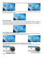
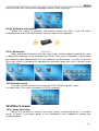
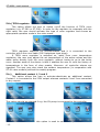
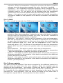
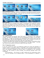
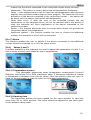
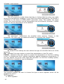
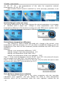
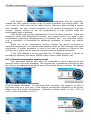
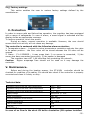
Tech
-1-
ST-408N – user's manual
Declaration of Confirmity No. 86/2013
Hereby, we declare under sole responsibility that the ST-408N
230V
50Hz
thermoregulator
manufactured
by
TECH,
headquartered in Wieprz 1047A, 34-122 Wieprz, is compliant
with the Regulation by the Ministry of Economy. (Journal of
Laws Dz.U. 155 Item 1089) of July 21, 2007 implementing
provisions of the Low Voltage Directive (LVD) 2006/95/EC of
January 16, 2007.
The
ST-408N
electromagnetic
controller
compatibility
has
(EMC)
been
with
tested
optimal
for
loads
applied.
For compliance assessment, harmonized standards were
used:
PN-EN 60730-2-9:2011, PN-EN 60730-1:2012.
Marked product CE: 04/2013.
Wieprz, 23 IV 2013
-2-
Tech
-3-
ST-408N – user's manual
I. Use
ST-408N thermoregulator is intended for controlling central heating installation.
The controller supports two mixing valves, DHW pump (of water boiler), circulating
pump and a solar collector. The controller may cooperate with two ST-61 modules,
which enables the user to control the total of five mixing valves. The controller
features weather control and weekly control functions and it may support three
two-state (standard) room regulators and one TECH regulator. The device has one
voltage contact (additional contact 1) and two dry contacts (additional contacts 2
and 3). It is also compatible with GSM module and Internet module.
Return temperature protection is another asset of the device. It prevents the
water in the short circulation from boiling and ensures that the temperature of
water returning to the CH boiler is not too low.
II.Principle of operation
Controller operation involves mixing the hot circulating water with the water
returning from the heating circuit in order to reach and maintain the set
temperature.
Pumps which are connected to each valve circuit help to distribute the water
throughout the system. A pump should be connected behind the mixing valve
whereas the temperature sensor should be placed behind both the pump and the
valve in order to ensure accurate measurement of the valve output temperature.
Note: if the valve controller and the CH boiler controller operate simultaneously in
one circuit, the pump may be connected from the CH boiler controller (the pump
output in the ST-408N regulator and in the additional module remains unconnected)
The device is controlled using a touch screen.
II.a) Main page
During normal operation, the graphic display of the regulator shows the main
page, which may differ depending on user's settings. The main screen shows the
following information:
• current and set temperatures of the active valves,
• current and set temperature of the water boiler
• current and set temperature of the buffer
• outdoor temperature
• time and day of the week
• operation mode of the pumps
The screen view shown above is the default one in ST-408N controllers. The user
may also switch to panel screen:
-4-
Tech
III. Main menu
III.a) Valve 1
In this submenu the user may adjust the basic settings of the first valve.
III.a.1) Set temperature
This option is used to set the desired temperature which will be
maintained by the first valve. The temperature may be adjusted in the main screen,
when Temp 1 is active. During proper operation, the temperature of water behind
the valve be approaching the set temperature of the valve.
III.a.2) Activated
This option is used to activate valve 1. When the valve is turned off, the pump
is also inactive. After connecting the controller to the power source, the valve is
always calibrated, even if it is deactivated. It prevents the valve from remaining in
dangerous position.
III.a.3) Calibration of the valve
This function enables the user to calibrate the first valve at any time. During this
process the valve is restored to its safe position – in the case of CH valve it is fully
-5-
ST-408N – user's manual
opened whereas in the case of floor valve it is closed.
III.b) Valve 2
In this submenu the user adjusts the basic parameters of the second valve similarly
as in the case of valve 1.
III.c) DHW pump (of the water boiler)
This function enables the user to adjust the parameters of DHW pump operation.
III.c.1) DHW set temperature
This function is used to adjust the set temperature of domestic water. It may be
done in the main screen of the controller when DHW view is active. After the water
in the water boiler reaches this temperature, the controller switches off the DHW
pump. The pump will be enabled again when the temperature drops below the set
value minus DHW hysteresis.
III.c.2) Operation modes
This function enables the user to switch off the DHW pump if it is not used, or
to activate automatic operation (the pump operates according to parameters
described in the following section).
III.c.3) DHW hysteresis
This option is used to set the hysteresis of the water boiler set temperature. It
is the difference between the set temperature (desired temp. of the water boiler)
and the temperature of returning to operation mode. For example, if the set
temperature is 55°C and the hysteresis value is 5 °C, the DHW pump is switched off
when the set temperature of 55°C is reached, and it is activated again when the
temperature drops to 50°C.
-6-
Tech
III.c.4)DHW pump activation threshold
This option is used to set the temperature of DHW pump activation (it is the
temperature measured by the CH boiler sensor). When the temperature remains
below this value, the pump is inactive, whereas when the temperature is above this
value, the pump is switched on and works until the set temperature is reached.
III.c.5) Weekly control (of the DHW pump)
This function is used to program daily changes of the water boiler
temperature. The range of set temperature deviation is +/- 100C.
Weekly control is explained in detail in section IV.d.17.
III.c.6) Maximum temperature
This function is used to set the maximum DHW temperature. After it has been
reached, the DHW pump is switched off.
III.c.7) Sensor
This function enables the user to choose the sensor which will serve as the
DHW sensor.
III.d) Circulating pump
This function is used to control the pump which mixes hot water between the CH
boiler and DHW receivers. After activating this function the user sets the 24-hour
cycle of pump pause and activation (with the accuracy of 30 minutes).
In order to make setting the 24-hour cycle easier, the user may copy a
selected time interval into the next one. After the operation plan is defined, the user
sets the pump operation time and the pump pause time while the previously
selected time interval is active. The user may easily delete the previously saved
settings in order to introduce new intervals.
-7-
ST-408N – user's manual
III.d) Operation modes
In this function the user may choose one of the three operation modes
available.
III.d.1) Water boiler priority
In this mode, the DHW pump is activated first and it operates until the set
DHW temperature is reached (the valves close completely and the valve pumps are
switched off). After the set temperature has been reached, the pump is switched off
and the mixing valves are activated (along with the pumps – according to their
settings).
The valves operate continuously until the water boiler temperature drops
below the set value minus hysteresis. Then, the valve pumps are switched off and
the DHW pump is switched on.
III.d.2) Parallel pumps
In this mode, all active pumps and valves operate simultaneously. The valves
maintain the set temperature and the water boiler is heated to the set temperature.
III.d.3) Summer mode
In this mode, the CH valves are closed to prevent unnecessary house heating. In the
case when the CH boiler temperature is too high, the valve will b e opened as an
emergency procedure (requires activation of return protection!)
In this mode the water boiler pump and the floor valves operate normally
according to their settings.
-8-
Tech
III.e) Manual mode
When the manual mode option is selected, the user can open and close the
valves (and the auxiliary valves if they are active) manually. It is also possible to
switch on/off each valve pump, DHW pump, circulating pump as well as the
additional contacts in order to check if the device works properly.
III.f) Time
Time option enables the user to set the current time and day of the week.
Setting the time is essential for weekly control to operate correctly.
III.g) Fitter's menu
The following sections provide detailed information on all functions which are
available in the fitter's menu.
III.e) Screen
After selecting Screen option, the user may customize the main screen
settings.
-9-
ST-408N – user's manual
III.e.1) Screen view
With this function the user can change the screen view switching between panel
screen and installation screen.
III.e.2) At night
By selecting At night option the user enters the panel enabling him/her to adjust the
screen view at night: As at daytime, Timer or Switched off. The set screen is
activated during nighttime, after the screen has not been touched for 20 seconds. In
order to return to the main menu, touch the screen.
III.e.3) Night from and Day from
In the following part of the menu the user may set the exact time of entering night
mode (Night from) and returning to day mode (Day from).
III.e.4)Brightness during the day and Brightness at night
This part of menu enables the user to adjust the screen brightness for both night
and day modes.
III.f) Language selection
- 10 -
Tech
Here the user may choose the language version of the controller.
III.g) Software information
When this option is selected, the display shows the logo of the CH boiler
manufacturer as well as the software version used in the regulator.
III.h) Protection
After selecting Protection icon, the main menu shows a panel enabling the user
to adjust the settings of the parental lock. When Auto-lock is selected, a panel used
for activating and deactivating the lock appears on the screen. In order to set the
PIN code, which is essential to operate the controller when the lock is active, press
PIN code icon.
III.i)Service menu
In order to enter the service menu of the ST-408N controller, enter
a 4-digit code. The code is available in TECH company.
IV.Fitter's menu
IV.a) Pump Anti-stop
When this function is active, the valve pump is switched on for 2 minutes
every 10 days. It prevents water in the installation from stagnation outside the
heating season.
- 11 -
ST-408N – user's manual
IV.b) TECH regulator
This option allows the user to switch on/off the function of TECH room
regulator (e.g. ST-280 or ST-298). In order for the regulator to cooperate with the
right valve, the user should activate this type of room regulator and choose an
appropriate operation mode in the valve menu.
TECH regulator supports RS communication and it is connected to the
controller with a four-core cable (RJ12 telephone-type plugs).
If TECH room regulator is switched on, apart from room temperature
regulation, the user may adjust the set temperature of the active valves and the
water boiler directly from the room regulator, without having to go to the boiler
room. Another asset of the device is that it enables the user to view the history of
temperatures in the form of clear graphs. Moreover, all controller alarms are
signalled. The user may also check the outdoor temperature (in cooperation with
ST-61 valve module) and set the weekly program.
IV.c)
Additional contact 1, 2 and 3
This option allows the user to activate-deactivate an additional contact.
Contact 1 is connected to the 230V output whereas contacts 2 and 3 are connected
to dry outputs.
IV.c.1) CH
This option should be selected if e.g. the CH pump is connected to the controller
•
- 12 -
Activation threshold – this option is used to set the temperature of device
Tech
•
•
activation. When the temperature is below the set value, the device is inactive
whereas when the temperature exceeds this value, the device is enabled.
Hysteresis – the temperature difference between device activation and its
deactivation (e.g. when the activation threshold is set to 60ºC and the
hysteresis value is 3ºC, the device will be activated when the temperature
reaches 60ºC and it will be disabled when the temperature drops to 57ºC).
Sensor – this option is used to select which sensor will provide temperature
information needed for the operation of the device connected to the additional
contact.
IV.c.2) DHW
This option should be selected when DHW pump is connected to the controller.
•
•
•
•
•
•
Activation threshold – this option is used to set the temperature of device
activation. When the temperature is below the set value, the device is inactive
whereas when the temperature exceeds this value, the device is enabled and
operates until the set temperature is reached.
Hysteresis – this option is used to set the hysteresis of the set temperature.
After the set temperature is reached, the device is switched off. It is switched
on again after the temperature on the sensor drops below the set temperature
minus hysteresis value (e.g. when the set temperature is 60ºC and the
hysteresis value is 3ºC, the device will be switched off when the temperature
reaches 60ºC and it will return to operation when the temperature drops to
57ºC).
Set temperature - This option is used to define the set temperature.
Maximum temperature – this option is used to set the maximum temperature
– when this temperature is reached, the device is switched off.
Sensor 1 - this option is used to select which sensor will provide temperature
information needed for the operation of the device connected to the additional
contact (activation threshold).
Sensor 2 - this option is used to select which sensor will provide temperature
information needed for the operation of the device connected to the additional
contact. (set temperature).
IV.c.3) Room regulator
This option should be selected if the device connected to the additional contact is to
operate using the signal from the room regulator. When the regulator has not
reached the set temperature – the contact is closed (the device is active). After the
temperature has been reached, the contact opens (the device is switched off).
It is possible for the additional device to work according to the signal from the
maximum of 4 room regulators. Then, the device will switch off only when each of
the regulators signals that its set temperature has been reached.
- 13 -
ST-408N – user's manual
IV.c.4) Weekly control
When this option is selected, the device connected to the additional contact operates
according to the weekly program – the user sets time intervals (with the accuracy of
30 minutes) at which the contact will close.
IV.c.5) Buffer
This option should be selected when buffer is connected to the additional contact.
The device will operate until the set temperature of buffer 'down' has been reached.
After the temperature drops below the set value of the buffer 'up', the device is
switched on again. The user may choose the sensors which will serve as upper and
lower sensors.
IV.c.6) DHW buffer
This option should be selected when DHW buffer is connected to the additional
contact. The device will operate until the set temperature of buffer 'up' and 'down'
are reached – in order for the pump to be switched off, both sensors must reach the
set temperature. After the set temperature of buffer 'up' is reached, the pump will
still operate for the period of time set by the user as the delay time.
Moreover, the device may operate according to weekly program (described in detail
in section IV.d.17), which controls the temperature of the upper sensor. The user
may choose which sensors will serve as upper and lower sensors.
IV.c.7) Operation control
If the user selects this option, the additional contact will control the operation of
another contact. If the device which is connected to the controlled contact fails to
switch on and the selected sensor fails to reach the set temperature within the delay
time, the controller activates the device which is connected to the controlling
contact. For this function to work correctly, the following settings need to be
configured:
•
set temperature – this function is used to define the set temperature which
must be reached by the selected sensor. If the temperature is reached, it
- 14 -
Tech
•
•
•
•
•
means that the device connected to the controlled contact works correctly.
Hysteresis – This option is used to define the set temperature hysteresis.
Delay – if the selected sensor fails to reach the set temperature after this time
elapses, the controlled contact does not work properly. The controller will force
activation of the device connected to the controlling contact – the device will
be active until the sensor reaches the set temperature.
Delay after error– if, after the error of the controlled contact, the set
temperature on the selected sensor will not be reached within this period of
time, the controller will force reactivation of the device connected to the
controlling contact.
Sensor – this function allows the user to choose which sensor will provide the
information about the temperature.
Additional contact – this function enables the user to choose the additional
contact, the operation of which will be controlled.
IV.c.7) Alarm
This function enables the user to decide if the device connected to the additional
contact should be switched on or off if an alarm occurs.
IV.d)
Valves 1 and 2
Functions available in this submenu are used to adjust the parameters of valve 1, so
that it works correctly and meets the user's expectations.
IV.d.1) Temperature control
This parameter determines water temperature measurement (control)
frequency behind the CH or DHW installation valve. If the sensor indicates a change
in temperature (deviation from the set value), then the electric valve will open or
close by the set stroke, in order to return to the preset temperature
IV.d.2) Opening time
This parameter defines the time needed for the valve actuator to open the
valve from 0% to 100% position. This value should be adjusted to the value given
on the actuator rating plate.
- 15 -
ST-408N – user's manual
IV.d.3) Single stroke
This is a maximum single stroke (opening or closing) that the valve may make
during one temperature sampling. If it is near the preset temperature, the stroke is
calculated on the basis of PROP_COEFF parameter value. The smaller the single
stroke, the more precisely the set temperature can be achieved. However, it takes
longer for the set temperature to be reached.
IV.d.4) Minimum opening
The parameter
determines the smallest valve opening. Thanks to this
parameter, the valve may be opened minimally, to maintain the smallest flow.
IV.d.5)Valve type
By means of this setting the user selects the type of controlled valve out of the
following:
CH – selected if the user wants to control the temperature in the CH circuit.
FLOOR – selected if the user wants to control the temperature of the floor heating
circuit. It protects the floor heating installation against dangerous temperature. If
the user selects CH as the valve type and connects it to the floor heating system,
the fragile floor installation may be damaged.
IV.d.6) Room regulator
This function enables the user to choose the type of room regulator which will be
assigned to valve 1
TECH regulator
➔ TECH regulator
- 16 -
Tech
➔
➔
When this type of regulator is selected, the valve works according to <room
temperature reduction> parameter. Activation of this regulator enables the
user to view the current temperature of the CH boiler, water boiler and the
valves. This regulator should be plugged to RJ (telephone-type) socket of the
ST-408N controller using a four-core cable with appropriate pins (to the
socket at the back of the controller)
TECH regulator algorithm
When this type of regulator is selected, the valve works according to <change
in valve set temp.> and <room temperature difference> parameters.
Activation of this regulator enables the user to view the current temperature of
the CH boiler, water boiler and the valves. This regulator should be plugged to
RJ (telephone-type) socket of the ST-408N controller using a four-core cable
with appropriate pins (to the socket at the back of the controller)
Standard regulator 1, 2 and 3
When this type of two-state regulator is selected, the valve works according to
<room temperature reduction> parameter. This regulator should be connected
to the controller in the place labelled Regulator pokojowy 1,2 lub 3 using a
two-core cable.
IV.d.7) Weather-based control
For the function of weather control to be active, the external sensor mustn't be
exposed to sunlight or influenced by the weather conditions. After it is installed in an
appropriate place, weather control function needs to be activated in the controller
menu.
For the valve to operate correctly, the user defines the set temperature
(behind the valve) for 4 intermediate external temperatures:
TEMP. FOR -20
TEMP. FOR-10
TEMP. FOR 0
TEMP. FOR10
Heating curve – it is a curve according to which the set controller
temperature is determined, on the basis of external temperature. In our
controller, this curve is constructed on the basis of four points of set
temperatures for respective values of external temperatures. Set temperatures
must be determined for the following external temperatures: -20ºC,-10ºC, 0ºC and
10ºC.
The more points constructing the curve, the greater its accuracy, which allows
its flexible shaping. In our opinion, four points seem a very good compromise
ensuring decent accuracy and easiness of setting the course of this curve.
In our controller:
XA = -20ºC,
XB = -10ºC,
XC = 0ºC,
XD = 10ºC,
- 17 -
ST-408N – user's manual
YA, YB, YC, YD – set temperatures of the valve for respective external
temperatures: XA, XB, XC, XD
After weather-based control is switched on, valve set temp. parameter is not
available.
IV.d.8) Change in valve set temp.
This setting determines by how many degrees the valve temperature is to increase
or
decrease with a single unit
change in room temperature (see: Room
temperature difference) This function is active only with TECH room regulator and it
is closely related to the Room temperature difference parameter.
IV.d.9) Room temperature difference.
This setting is used to define the single unit change in the current room
temperature (with the accuracy of 0.1°C) at which a predefined change in the set
temperature of the valve will be introduced (function available only with TECH room
regulator).
Example:
setting: room temperature difference 0,5ºC
setting: change in set valve temperature 1ºC
setting: set temperature of the valve 40ºC
setting: set temperature of the room regulator 23ºC
Case 1. If the room temperature rises to 23.5ºC (by 0.5ºC ) the valve will close to
such an extent as to have 39ºC as a set-point (by 1ºC ).
Case 2. If the room temperature drops to 22ºC (by 1ºC) the valve will open to such
an extent as to have 42ºC as a set-point (by 2ºC).
IV.d.10) Room temperature reduction
This function is active only if the valve cooperates with the two-state
(standard) room regulator. The user defines the value of valve temperature
reduction which will be performed when the room regulator reaches the set
- 18 -
Tech
temperature.
IV.d.11) Proportionality coefficient
Proportionality coefficient is used for defining valve stroke. The closer the
preset temperature, the smaller the stroke. If the coefficient value is high, the valve
will take less time to open but at the same time the opening degree will be less
accurate. The following formula is used to calculate the percent of a single opening:
(SET_TEMP - SENSOR_TEMP) * (PROP_COEFF /10)
IV.d.12) Maximum floor temperature
It is the maximum temperature which does no damage the floor heating
installation. This setting is used when the valve type is set as floor valve. After this
temperature is reached, the valve closes completely and the user is informed about
it by means of an appropriate alarm. When the maximum floor temperature is
reached, CH boiler protection function is deactivated. In such a case, protection of
the floor installation is assigned higher priority.
IV.d.13) Opening direction
If, after connecting the valve to the controller, it turns out that it is connected
the other way round, then the power supply cables do not have to be switched.
Instead, it is enough to change the opening direction in this parameter:
LEFT*
RIGHT *
IV.d.14) CH boiler protection
- 19 -
ST-408N – user's manual
The protection against too high return temperature serves to prevent the
hazardous growth in CH boiler temperature. The user sets the maximum
acceptable return temperature.
In the case of the hazardous growth in
temperature, the valve begins to open to house installation in order to cool the CH
boiler down. This function is activated permanently (it may be deactivated only in
service menu).
IV.d.15)Return protection
This function permits setting the boiler protection against too cool water
returning from the main circulation, which could cause low-temperature boiler
corrosion. The return protection involves closing the valve when the temperature
is too low, until the short circulation of the boiler reaches the appropriate
temperature. After activating it, the user presets the minimum acceptable return
temperature.
IV.d.16) Pump activation:
This option enables the user to select the working mode of a pump. A
pump will be activated: always (the pump operates all the time, regardless of
temperatures), never (the pump is permanently deactivated and the regulator
controls only valve operation), above the threshold (the pump is activated above
the set activation temperature). If the pump is to be activated above the
threshold, the user should also define the threshold temperature of pump activation.
When the CH pump room regulator function is activated, the CH pump is switched
off after reaching the set temperature (if always or above the threshold option is
selected).
IV.d.17) IV.d.17) Weekly control (weekly program)
This function is used for programming daily changes of the temperature
- 20 -
Tech
behind the valve. The set temperature deviations are in the range of +/-100C
Step I:
First the user must set current time and date (Fitter's menu>Timer)
Step II:
The user sets the temperatures for each particular weekday (Set mode 1):
Monday-Sunday
In this mode, specific time and the requested deviations from the preset
temperature should be defined (by how many degrees the temperature should
rise or drop at a given time) for each day of the week. Additionally, to facilitate the
use of the device, it is possible to copy the settings.
Example:
Monday
set: 300 AM, temp -100C (temperature change– 100C)
set: 4 00 AM, temp -100C (temperature change – 100C)
set: 5 00 AM, temp -100C (temperature change – 100C)
In this case, if the set temperature of the valve is 600C, from 300 AM to 600 AM on
Monday the set temperature will drop by 100C, so it will be 500C.
Instead of setting the temperature for particular days, mode 2 enables the user to
set the temperature for all working days (Monday-Friday) and for the weekend
(Saturday-Sunday) – Set mode 2
Monday-Friday ; Saturday– Sunday
In this mode, specific time and the requested deviations from the preset
temperature should be defined for both working days (Monday-Friday) and the
weekend (Saturday-Sunday)
Example:
Monday-Friday
set: 3 00 AM, temp -10°C (temperature change – 10°C)
set: 4 00 AM, temp -10°C (temperature change – 10°C)
set: 5 00 AM , temp -10°C (temperature change – 10°C)
Saturday-Sunday
set: 4 00 PM, temp 5°C ( temperature change +5°C)
set: 5 00 PM, temp 5°C ( temperature change +5°C)
set: 6 00 PM, temp 5°C ( temperature change +5°C)
In this case, if the set temperature of the valve is 60°C, on each weekday from
Monday-Friday from 300AM to 600AM the set temperature will drop by 100C, so it
will be 500C. During the weekend, from 4 00 PM to 6 00 PM the set temperature of
the valve will increase by 5°C, so it will be 65°C.
- 21 -
ST-408N – user's manual
Step III (Mode):
The user activates one of the two previously defined modes (Mode 1, Mode2)
or deactivates weekly control completely.
After one of the modes has been activated, the value of the currently set
deviation will be flashing on the controller main page, informing the user that the
weekly control is active.
Delete data function allows the user to easily delete all previously saved settings
of the weekly program, in order to introduce new settings.
IV.d.18) CH sensor
This function enables the user to choose which sensor will serve as CH sensor.
IV.d.18)Valve deactivation
When this function is selected, the valve operation depends on the external
temperature. The user may set the temperature at which the valve should be
deactivated during day and night. It is possible the define the time when the
controller will operate in day mode and night mode. The user sets the hysteresis of
valve deactivation temperature for the night mode and day mode.
IV.d.18) Factory settings
This function enables the user to restore the factory settings for a particular valve.
Restoring factory settings does not change the selected valve type (CH or floor).
IV.e) Auxiliary valve 1, auxiliary valve 2
The user may control two additional valves (optional) after purchasing
two independent ST-61 modules.
After each additional module is connected, it must be registered by
entering the module number ( written on ST-61 casing). Then, the auxiliary valve
ma be configured.
In the case of auxiliary valve, the following settings must be defined:
➢ activated (valve activation after the configuration is completed)
➢ temperature control
➢ opening time
➢ single stroke
➢ minimum opening
➢ valve type
➢ room regulator
- 22 -
Tech
weather-based control
➢ change in valve set temp.
➢ room temperature difference
➢ room temperature reduction
➢ proportionality coefficient
➢ maximum floor temperature
➢ pump activation
➢ factory settings
➢ valve removal – this option is used to remove the valve from the controller
memory. Valve removal is used e.g. at disassembling the valve or module
replacement (re-registration of a new module is necessary)
nformation on how to set those parameters which have not been described in detail
above, may be found in section Valve 1,2 and 3.
➢
IV.f)Internet module
Note: This type of control is available only after purchasing and connecting an
additional controlling module ST-500 which is not
included in the standard
controller set.
Internet module is a device enabling the user remote control of the CH boiler
via the Internet or local network . The user controls the status of all Ch boiler
system devices on the home computer screen and the operation of each device is
presented in the form of animation.
Apart from the possibility to view the temperature of every sensor, the user
can change the set temperatures for both the pumps and the mixing valves.
After switching the module on and selecting DHCP option, the controller
automatically downloads such parameters as IP address, IP mask, gateway address
and DNS address from the local network. If any problems arise when downloading
the network parameters, they may be set manually. The procedure of obtaining
these parameters is described in detail in the instruction manual of the Internet
Module.
Module password reset function may be used when the user has changed the
default password on the login page. If the user's new password is lost, the default
password may be restored by resetting the module password.
IV.g) GSM module
Note: This type of control is available only after purchasing and connecting an
additional controlling module ST-65 which is not included in the standard controller
set.
- 23 -
ST-408N – user's manual
GSM Module is an optional device which, cooperating with the controller,
enables the user remote control of the CH boiler operation via mobile phone. The
user is sent an SMS each time an alarm occurs. Moreover, after sending a certain
text message, the user receives feedback on the current temperature of all the
sensors. Remote change of the set temperatures is also possible after the
authorisation code is entered.
GSM Module may operate independently of the CH boiler controller. It has two
additional inputs with temperature sensors, one contact input to be used in any
configuration (detecting closing/opening of contacts) and one controlled output
(e.g. a possibility of connecting an additional contractor to control any electric
circuit)
When any of the temperature sensors reaches the preset maximum or
minimum temperature, the module automatically sends an SMS message with such
information. A similar procedure is used in the case of opening or closing of the
contact input, which may be used as a simple means of property protection.
If the GSM Module is to be used with the ST-408N controller, it should be
activated by selecting ON option (MENU>Fitter's menu>GSM Module>ON)
IV.h) External temperature measurement
This parameter defines how often the temperature value measured by the
external sensor should be averaged. The temperature is measured continuously and
the value is averaged and refreshed every 60 seconds (factory setting). The setting
range available is 1-600 seconds.
IV.i) External sensor calibration
External sensor calibration is performed when mounting the regulator or after it
has been used for a long time, if the external temperature displayed on the sensor
differs from the actual temperature. Calibration setting range is from -10°C to
+10°C with the accuracy of 0,1°C.
- 24 -
Tech
IV.j) Factory settings
This option enables the user to restore factory settings defined by the
manufacturer.
V. Protection
In order to ensure safe and failure-free operation, the regulator has been equipped
with a range of safeguards. In case of alarm, a sound signal is activated and the
display shows an appropriate message.
To restore operation, touch the screen.
During an alarm, manual operation is available. However, the user should
ensure that such activity will not cause any damage.
The controller is equipped with the following alarm protection:
1. Temperature alarm – it stops the valve temperature regulation and sets the valve
in its safest position - the floor valve will be closed whereas the CH valve will be
opened.
2. Alarm - C1-4 SENSOR – it may mean that: 1) no sensor is connected, 2) the
sensor has been connected incorrectly, 3) the sensor is damaged
The regulator has a WT 1,6A tube fuse-link protecting the network.
Caution:
Higher amperage fuse should not be used as it may damage the
controller.
V. Maintenance.
Before and during the heating season, the ST-408N controller should be
checked for condition of its cables. You should also check if the controller is properly
mounted and clean it if dusty or dirty.
Technical data:
Regulation range of the CH valve temperature
10oC : 90oC
Regulation range of the floor valve temperature
10oC : 55oC
Regulation range of the DHW tank temperature
1oC : 80oC
Supply voltage
230V/50Hz +/- 10%
Power consumption
max. 4W
Thermal resistance of the sensors
-25oC : 90oC
Ambient temperature
5oC : 50oC
Load on each output
0,5A
Fuse link
6,3A
! WARNING !
In case of no flow in the short CH boiler circulation (CH system installed
- 25 -
ST-408N – user's manual
incorrectly), the return sensor should be placed on hot water output of
the CH boiler in order to prevent the water from boiling.
VI. Installation
Caution: The device should be installed by a qualified person. During
installation the device mustn't be powered! (make sure the plug is
disconnected from the power supply!)
Contents
I. Use................................................................................................................................................................4
II.Principle of operation...................................................................................................................................4
III. Main menu.................................................................................................................................................5
IV.Fitter's menu.............................................................................................................................................13
V. Protection..................................................................................................................................................28
V. Maintenance..............................................................................................................................................28
VI. Installation...............................................................................................................................................29
- 26 -
Tech
Care for the natural environment is our priority. Being aware of the fact that we manufacture electronic devices obligates
us to dispose of used elements and electronic equipment in a manner which is safe for nature. As a result, the company has
received a registry number assigned by the Main Inspector of Environmental Protection. The symbol of a crossed out
rubbish bin on a product means that the product must not be thrown out to ordinary waste bins. By segregating waste
intended for recycling, we help protect the natural environment. It is the user's responsibility to transfer waste electrical
and electronic equipment to the selected collection point for recycling of waste generated from electronic and electrical
equipment.
- 27 -
ST-408N – user's manual
- 28 -


![Manuel d`utilisation Régulation TECH ST3[...]](http://vs1.manualzilla.com/store/data/006377962_1-761c4fa99f631e7c2b8551b5818edead-150x150.png)