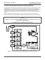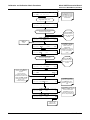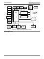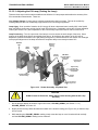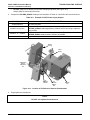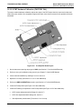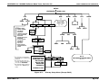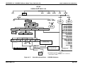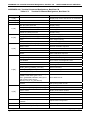
1
MANUAL ADDENDUM MODEL M100EH UV FLUORESCENCE SO2 ANALYZER (Standalone Addendum – For use with the M100E Instruction Manual, P/N 04515) © TELEDYNE ADVANCED POLLUTION INSTRUMENTATION (T-API) 9480 CARROLL PARK DRIVE SAN DIEGO, CA 92121-5201 USA Toll-free Phone: Phone: Fax: Email: Website: Copyright 2006 Teledyne Advanced Pollution Instrumentation. PRINT DATE: 11 March 2009 800-324-5190 858-657-9800 858-657-9816 [email protected] http://www.teledyne-api.com/ 04621 Rev A8 DCN 5342 11 March 2009 Model 100EH Instruction Manual M100EH Documentation Addendum to M100E Manual (P/N 04515) SAFETY MESSAGES Your safety and the safety of others is very important. We have provided many important safety messages in this addendum. Please read these messages carefully. A safety message alerts you to potential hazards that could hurt you or others. Each safety message is associated with a safety alert symbol. These symbols are found in the manual and inside the instrument. The definition of these symbols is described below: GENERAL SAFETY HAZARD: Refer to the instructions for details on the specific hazard. CAUTION: Hot Surface Warning CAUTION: Electrical Shock Hazard TECHNICIAN SYMBOL: All operations marked with this symbol are to be performed by qualified maintenance personnel only. CAUTION The analyzer should only be used for the purpose and in the manner described in this addendum. If you use the analyzer in a manner other than that for which it was intended, unpredictable behavior could ensue with possible hazardous consequences. 05243 Rev A2 1 Model 100EH Instruction Manual M100EH Documentation Addendum to M100E Manual (P/N 04515) TABLE OF CONTENTS 1. M100EH DOCUMENTATION................................................................................................................. 7 1.1. Using This Manual Addendum .........................................................................................................7 2. SPECIFICATIONS, APPROVALS & WARRANTY ....................................................................................... 9 2.1. Specifications.............................................................................................................................9 2.2. CE Mark Compliance.................................................................................................................. 10 2.3. Warranty ................................................................................................................................ 10 3. GETTING STARTED..........................................................................................................................13 3.1. Unpacking and Initial Setup .......................................................................................................... 13 3.1.1. Electrical Connections:.......................................................................................................... 14 3.1.1.1. External Pump.............................................................................................................. 14 3.2. Pneumatic Connections:.............................................................................................................. 15 3.2.1.1. Pneumatic Connections to M100EH Basic Configuration: ........................................................... 15 3.2.1.2. Connections with Internal Valve Options Installed .................................................................... 16 3.2.2. M100EH Layout .................................................................................................................. 16 3.3. Initial Operation ........................................................................................................................ 18 3.3.1. Warning Messages .............................................................................................................. 18 3.3.2. Test Functions.................................................................................................................... 18 3.3.3. Interferents for SO2 Measurements .......................................................................................... 19 4. FREQUENTLY ASKED QUESTIONS .....................................................................................................21 5. OPTIONAL HARDWARE AND SOFTWARE .............................................................................................23 5.1. Zero/Span Valves (Option 50) ....................................................................................................... 23 5.2. Internal Zero/Span Gas Generator (Option 51).................................................................................... 23 5.3. Zero and Two Span Point Valve Option (OPT 52) ................................................................................ 24 5.4. Hydrocarbon Kicker Option (OPT 65)............................................................................................... 25 6. OPERATING INSTRUCTIONS..............................................................................................................27 6.1. Warning Messages .................................................................................................................... 27 6.2. Test Functions ......................................................................................................................... 27 6.2.1. Test Channel Output ............................................................................................................ 27 6.2.2. Range Units ...................................................................................................................... 28 6.2.3. Using the M100EH with a Hessen Protocol Network ....................................................................... 28 6.2.4. Default iDAS Channels.......................................................................................................... 29 6.2.5. Remote Operation Using the External Digital I/O ........................................................................... 29 6.2.5.1. Status Outputs ............................................................................................................. 29 6.2.5.2. Control Inputs............................................................................................................... 30 7. CALIBRATION AND CALIBRATION CHECK PROCEDURES ......................................................................31 7.1. Manual Calibration with the Zero and Two Span Point Valve Option (OPT 52)installed..................................... 31 7.2. Manual Calibration Check with the Zero and Two Span Point Valve Option (OPT 52)installed. ........................... 33 8. INSTRUMENT MAINTENANCE ............................................................................................................35 8.1. Maintenance Schedule................................................................................................................ 35 8.2. Predictive Diagnostics................................................................................................................. 35 9. THEORY OF OPERATION ..................................................................................................................37 9.1. The UV Light Path ..................................................................................................................... 37 9.1.1. The Reference Detector ........................................................................................................ 38 9.1.2. Direct Measurement Interferences ............................................................................................ 38 9.2. Pneumatic Operation.................................................................................................................. 38 9.2.1. Sample Gas Flow ................................................................................................................ 38 9.2.2. Pneumatic Sensors .............................................................................................................. 39 9.2.2.1. Sample Pressure Sensor ................................................................................................. 39 9.2.2.2. Vacuum Pressure Sensor ................................................................................................ 39 9.2.2.3. Sample Flow Calculation ................................................................................................. 40 9.3. Electronic Operation................................................................................................................... 41 10. TROUBLESHOOTING & REPAIR ........................................................................................................43 10.1.1. Fault Diagnosis with Warning Messages ................................................................................... 43 10.1.2. Fault Diagnosis with Test Functions ......................................................................................... 43 10.2. Subsystem Checkout ................................................................................................................ 43 10.2.1. Pneumatic Sensor Assembly ................................................................................................. 43 10.3. Repair Procedures ................................................................................................................... 44 05243 Rev A2 3 M100EH Documentation Model 100EH Instruction Manual Addendum to M100E Manual (P/N 04515) 10.3.1. Repairing the Sample Gas Flow Control Assembly ....................................................................... 44 10.3.2. Sensor Module Repair & Cleaning........................................................................................... 45 10.3.2.1. Adjusting the UV Lamp (Peaking the Lamp) ......................................................................... 46 10.3.2.2. PMT Hardware Calibration (FACTORY CAL) ........................................................................ 48 10.4. Technical Assistance ................................................................................................................ 50 LIST OF FIGURES Figure 3-1: Figure 3-2: Figure 3-3: Figure 3-4: Figure 5-1: Figure 5-2: Figure 5-3: Figure 5-4: Figure 6-1: Figure 9-1: Figure 9-2: Figure 9-3: Figure 9-4: Figure 10-1: Figure 10-2: Figure 10-3: Figure 10-4: Figure 10-5: Example of Pneumatic Connections to M100EH External Pump........................................ 15 Pneumatic Connections to M100EH with Zero and Two Span Point Valve Option ................... 16 Internal Pneumatic flow for M100EH in Basic Configuration ............................................ 16 M100EH Layout (Basic Unit – No Valve Options) ......................................................... 17 Pneumatic Diagram of the M100EH With Z/S Option Installed. ......................................... 23 Pneumatic Diagram of the M100EH With 2-Span Point Option Installed............................... 24 Hydrocarbon Scrubber (Kicker) – OPT 65 .................................................................. 25 M100EH Internal Pneumatic Diagram with Hydrocarbon Scrubber Installed. ......................... 26 Control Input Connector ....................................................................................... 30 UV Light Path ................................................................................................... 37 Pneumatic Diagram of the M100EH – Base Configuration............................................... 39 M100EH Electronic Block Diagram .......................................................................... 41 M100EH Power Distribution Block Diagram ................................................................ 42 Flow Control Assembly ........................................................................................ 44 Sensor Module Wiring and Pneumatic Fittings............................................................. 45 Shutter Assembly - Exploded View .......................................................................... 46 Location of UV Reference Detector Potentiometer ........................................................ 47 Pre-Amplifier Board Layout ................................................................................... 48 LIST OF TABLES Table 2-1: Table 3-1: Table 2-1: Table 5-1: Table 6-1: Table 6-2: Table 6-3: Table 6-4: Table 6-5: Table 6-6: Table 9-2: Table 10-1: Table 10-2: Table 10-3: 4 Model 100EH Basic Unit Specifications........................................................................ 9 Inlet / Outlet Connector Nomenclature ....................................................................... 15 Possible Warning Messages at Start-Up .................................................................... 18 Two-Point Span Valve Operating States..................................................................... 25 Additional M101EH Warning Messages ..................................................................... 27 Additional M100EH Test Functions ........................................................................... 27 Additional M101EH Test Parameters Available for Analog Output A3 .................................. 27 M100EH Default Hessen Status Bit Assignments .......................................................... 28 Status Output Signals .......................................................................................... 29 Control Input Signals ........................................................................................... 30 Predictive Uses for Test Functions ........................................................................... 35 Warning Messages - Indicated Failures ..................................................................... 43 Test Functions - Possible Causes for Out-Of-Range Values ............................................. 43 Example of HVPS Power Supply Outputs ................................................................... 47 05243 Rev A2 Model 100EH Instruction Manual M100EH Documentation Addendum to M100E Manual (P/N 04515) LIST OF APPENDICES APPENDIX A - VERSION SPECIFIC SOFTWARE DOCUMENTATION APPENDIX A-1: M100EH Software Menu Trees, Revision C.0 APPENDIX A-2: Setup Variables For Serial I/O, Revision C.0 APPENDIX A-3: Warnings and Test Functions, Revision C.0 APPENDIX A-4: M100EH Signal I/O Definitions, Revision C.0 APPENDIX A-5: M100EH iDAS Functions, Revision C.0 APPENDIX A-6: Terminal Command Designators, Revision C.0 APPENDIX B - M100EH SPARE PARTS LIST APPENDIX C - REPAIR QUESTIONNAIRE - M100E APPENDIX D - ELECTRONIC SCHEMATICS USER NOTES: 05243 Rev A2 5 Model 100EH Instruction Manual M100EH Documentation Addendum to M100E Manual (P/N 04515) 1. M100EH DOCUMENTATION NOTE Throughout this addendum, words printed in capital, bold letters, such as SETUP or ENTR represent messages as they appear on the analyzer’s front panel display NOTE The flowcharts in this addendum contain typical representations of the analyzer’s display during the various operations being described. These representations are not intended to be exact and may differ slightly from the actual display of your instrument. Thank you for purchasing the Model 100EH UV Fluorescence SO2 Analyzer! The documentation for this instrument is available in either printed format or in electronic format on a CD-ROM. The electronic manual is in Adobe® Systems Inc. “Portable Document Format”. The Adobe® Acrobat Reader® software, which is necessary to view these files, can be downloaded for free from the internet at http://www.adobe.com/. The electronic version of the manual has many advantages: Keyword and phrase search feature Figures, tables and internet addresses are linked so that clicking on the item will display the associated feature or open the website. A list of chapters and sections as well as thumbnails of each page are displayed to the left of the text. Entries in the table of contents are linked to the corresponding locations in the manual. Ability to print sections (or all) of the manual Additional documentation for the Model 100EH UV Fluorescence SO2 Analyzer is available from Teledyne Instruments’ website at http://www.teledyne-api.com/manuals/ APICOM software manual, part number 03945 Multi-drop manual, part number 01842 DAS Manual, part number 02837. 1.1. Using This Manual Addendum This manual addendum has the same overall structure as that of the M100E operator’s manual, to simplify referring between the two. The manual has the following sections: 05243 Rev A2 7 M100EH Documentation Model 100EH Instruction Manual Addendum to M100E Manual (P/N 04515) Table of Contents: Outlines the contents of the addendum in the order the information is presented. This is a good overview of the topics covered in the manual. There is also a list of tables, a list of figures and a list of appendices. Specifications and Warranty This section contains a list of the analyzer’s performance specifications, a description of the conditions and configuration under which EPA equivalency was approved and Teledyne Instrument’s warranty statement. Getting Started: A concise set of instructions for setting up, installing and running your analyzer for the first time. FAQ: Answers to the most frequently asked questions about operating the analyzer. Optional Hardware & Software A description of optional equipment to add functionality to your analyzer. Operation Instructions This section includes step by step instructions for operating the analyzer and using its various features and functions. Calibration Procedures General information and step by step instructions for calibrating your analyzer. Instrument Maintenance Description of preventative maintenance procedures that should be regularly performed on you instrument to assure good operating condition. Theory of Operation This section describes the aspects of M100EH operation that differ from the M100E manual. Maintenance & Troubleshooting Section: This section includes pointers and instructions for diagnosing problems that are specific to the M100EH. The M100E manual has a more complete troubleshooting section, most of which also applies to the M100EH. Appendices: For easier access and better updating, some information has been separated out of the manual and placed in a series of appendices at the end of this addendum. These include: software menu trees, warning messages, definitions of iDAS & serial I/O variables, spare parts list, repair questionnaire, interconnect listing and drawings, and electronic schematics. 8 05243 Rev A2 Model 100EH Instruction Manual Specifications, Approvals & Warranty Addendum to M100E Manual (P/N 04515) 2. SPECIFICATIONS, APPROVALS & WARRANTY 2.1. Specifications Table 2-1: Min/Max Range (Physical Analog Output) Model 100EH Basic Unit Specifications In 1ppb increments from 10ppm to 5,000 ppm, dual ranges or auto ranging Measurement Units ppm, mg/m3 (user selectable) Zero Noise1 0.05 ppm rms Span Noise1 Lower Detectable Limit < 0.5% of reading (above 50 ppm) 2 0.1 ppm rms Zero Drift (24 hours) < 1 ppm Zero Drift (7 days) < 2 ppm Span Drift (7 Days) < 0.5% FS Linearity 1% of full scale Precision 0.5% of reading1 Temperature Coefficient < 0.1% per oC Voltage Coefficient < 0.05% per V 1 Lag Time 5 sec Rise/Fall Time1 95% in < 30 sec Sample Flow Rate 700 cm3/min. ±10% Temperature Range 5-40oC Humidity Range 0 - 95% RH, non-condensing Dimensions H x W x D 7" x 17" x 23.5" (178 mm x 432 mm x 597 mm) Weight, Analyzer (Basic Configuration) 45 lbs (20.5 kg) w/internal pump Weight, Pump Pack 16 lbs (7 kg) AC Power Rating 100 V, 50/60 Hz (3.25A); 115 V, 60 Hz (3.0 A); 220 – 240 V, 50/60 Hz (2.5 A) Environmental Installation category (over-voltage category) II; Pollution degree 2 Analog Outputs Three (3) Outputs Analog Output Ranges 100 mV, 1 V, 5 V, 10 V, 2-20 or 4-20 mA isolated current loop. All Ranges with 5% Under/Over Range Analog Output Resolution 1 part in 4096 of selected full-scale voltage Status Outputs 8 Status outputs from opto-isolators Control Inputs 6 Control Inputs, 3 defined, 3 spare Serial I/O One (1) RS-232; One (1) RS-485 (2 connecters in parallel) Baud Rate : 300 – 115200: Optional Ethernet Interface Certifications EN61326 (1997 w/A1: 98) Class A, FCC Part 15 Subpart B Section 15.107 Class A, ICES-003 Class A (ANSI C63.4 1992) & AS/NZS 3548 (w/A1 & A2; 97) Class A. IEC 61010-1:90 + A1:92 + A2:95, 1 As defined by the USEPA. 2 Defined as twice the zero noise level by the USEPA. 05243 Rev A2 9 Specifications, Approvals & Warranty Model 100EH Instruction Manual Addendum to M100E Manual (P/N 04515) 2.2. CE Mark Compliance Emissions Compliance The Teledyne-Advanced Pollution Instrumentation UV Fluorescence SO2 Analyzer M100EH was tested and found to be fully compliant with: EN61326 (1997 w/A1: 98) Class A, FCC Part 15 Subpart B Section 15.107 Class A, ICES-003 Class A (ANSI C63.4 1992) & AS/NZS 3548 (w/A1 & A2; 97) Class A. Tested on 21 February 2003 - 08 March 2003 at CKC Laboratories, Inc., Report Number CE03-021A. Safety Compliance The Teledyne-Advanced Pollution Instrumentation UV Fluorescence SO2 Analyzer M100EH was tested and found to be fully compliant with: IEC 61010-1:90 + A1:92 + A2:95, Issued by CKC Laboratories on 4 April 2003, Report Number WO-80146. 2.3. Warranty WARRANTY POLICY (02024D) Prior to shipment, T-API equipment is thoroughly inspected and tested. Should equipment failure occur, T-API assures its customers that prompt service and support will be available. COVERAGE After the warranty period and throughout the equipment lifetime, T-API stands ready to provide on-site or in-plant service at reasonable rates similar to those of other manufacturers in the industry. All maintenance and the first level of field troubleshooting is to be performed by the customer. NON-API MANUFACTURED EQUIPMENT Equipment provided but not manufactured by T-API is warranted and will be repaired to the extent and according to the current terms and conditions of the respective equipment manufacturers warranty. GENERAL During the warranty period, T-API warrants each Product manufactured by T-API to be free from defects in material and workmanship under normal use and service. Expendable parts are excluded. If a Product fails to conform to its specifications within the warranty period, API shall correct such defect by, in API's discretion, repairing or replacing such defective Product or refunding the purchase price of such Product. The warranties set forth in this section shall be of no force or effect with respect to any Product: (i) that has been altered or subjected to misuse, negligence or accident, or (ii) that has been used in any manner other than in accordance with the instruction provided by T-API, or (iii) not properly maintained. 10 05243 Rev A2 Model 100EH Instruction Manual Specifications, Approvals & Warranty Addendum to M100E Manual (P/N 04515) THE WARRANTIES SET FORTH IN THIS SECTION AND THE REMEDIES THEREFORE ARE EXCLUSIVE AND IN LIEU OF ANY IMPLIED WARRANTIES OF MERCHANTABILITY, FITNESS FOR PARTICULAR PURPOSE OR OTHER WARRANTY OF QUALITY, WHETHER EXPRESSED OR IMPLIED. THE REMEDIES SET FORTH IN THIS SECTION ARE THE EXCLUSIVE REMEDIES FOR BREACH OF ANY WARRANTY CONTAINED HEREIN. API SHALL NOT BE LIABLE FOR ANY INCIDENTAL OR CONSEQUENTIAL DAMAGES ARISING OUT OF OR RELATED TO THIS AGREEMENT OF T-API'S PERFORMANCE HEREUNDER, WHETHER FOR BREACH OF WARRANTY OR OTHERWISE Terms and Conditions All units or components returned to T-API should be properly packed for handling and returned freight prepaid to the nearest designated Service Center. After the repair, the equipment will be returned, freight prepaid. 05243 Rev A2 11 Model 100EH Instruction Manual Getting Started Addendum to M100E Manual (P/N 04515) 3. GETTING STARTED 3.1. Unpacking and Initial Setup CAUTION To avoid personal injury, always use two persons to lift and carry the Model 100EH. 1. Inspect the received packages for external shipping damage. If damaged, please advise the shipper first, then T-API. 2. Included with your analyzer is a printed record (Form number 04989) of the final performance characterization performed on your instrument at the factory. This record is an important quality assurance and calibration record for this instrument. It should be placed in the quality records file for this instrument. 3. Carefully remove the top cover of the analyzer and check for internal shipping damage. Remove the set screw located in the top, center of the rear panel Remove the screws fastening the top cover to the unit (four per side). Lift the cover straight up. 05243 Rev A2 13 Getting Started Model 100EH Instruction Manual Addendum to M100E Manual (P/N 04515) NOTE Printed circuit assemblies (PCAs) are sensitive to electro-static discharges too small to be felt by the human nervous system. Failure to use ESD protection when working with electronic assemblies will void the instrument warranty. See Chapter 12 of the M100E Manual (P/N 04515) for more information on preventing ESD damage. CAUTION Never disconnect electronic circuit boards, wiring harnesses or electronic subassemblies while the unit is under power. 4. Inspect the interior of the instrument to make sure all circuit boards and other components are in good shape and properly seated. 5. Check the connectors of the various internal wiring harnesses and pneumatic hoses to make sure they are firmly and properly seated. 6. Verify that all of the optional hardware ordered with the unit has been installed. These are checked on the paperwork (Form 04989) accompanying the analyzer. 3.1.1. Electrical Connections: For full details on the electrical connections of the M100EH, please refer to the M100E user’s manual (#04515), Chapter 3. 3.1.1.1. External Pump The M100EH is equipped with an external pneumatic pump. This pump is powered separately from the instrument via it’s own power cord. The pump has no ON/OFF switch and should begin operating as soon as it is plugged into a live power supply. CAUTION 14 Check the voltage / frequency label on the rear panel of the instrument and on the external pump for compatibility with the local power. Do not plug in either the analyzer or the pump unless the voltages or frequencies are correct. Power connection must have a functioning ground connection. Do not defeat the ground wire on power plug. Turn off analyzer power before disconnecting or connecting eletrical subassemblies. Do not operate with cover off. 05243 Rev A2 Model 100EH Instruction Manual Getting Started Addendum to M100E Manual (P/N 04515) 3.2. Pneumatic Connections: NOTE To prevent dust from getting into the analyzer, it was shipped with small plugs inserted into each of the pneumatic fittings on the rear panel. Make sure that all dust plugs are removed before attaching exhaust and supply gas lines. Table 3-1: Inlet / Outlet Connector Nomenclature REAR PANEL LABEL FUNCTION Sample Connects the sample gas to the analyzer. When operating the analyzer without zero span option, this is also the inlet for any calibration gases. Exhaust Connect an exhaust gas line to this port to the inlet of the external pump. Zero Air On Units with zero/span valve option installed, this port connects the zero air gas or the zero air cartridge to the analyzer. Figure 3-5 of the M100E Manual (P/N 04515) shows the internal pneumatic flow of the M100E in its standard configuration. For a diagram of the internal pneumatic flow of the M100EH, see Figure 3-2 of this addendum. 3.2.1.1. Pneumatic Connections to M100EH Basic Configuration: The pneumatic connections for the M100EH analyzer in its basic configuration are nearly identical to those described the M100E Manual (P/N 04515) Section 3.1.2.2 except that the M100EH has an external pump. Therefore: A pneumatic line of ¼” PTEF must be attached between the analyzer’s exhaust port and the inlet port of the pump. The exhaust from must be vented outside the shelter or immediate area surrounding the instrument using a maximum of 10 meters of 1/4” PTFE tubing. MODEL 701 Zero Air Generator VENT here if sample gas is supplied under pressure Sample VENT at HIGH Concentration Calibrated SO2 MODEL 700 Gas Dilution Calibrator Source o SAMPLE Gas Removed during Calibration EXHAUST Span PUMP MODEL 100EH Zero Air vented outside immediate area Figure 3-1: Example of Pneumatic Connections to M100EH External Pump This change is true for all configurations and variations of the M100EH. 05243 Rev A2 15 Getting Started Model 100EH Instruction Manual Addendum to M100E Manual (P/N 04515) 3.2.1.2. Connections with Internal Valve Options Installed An additional valve option (Option 52 - Zero & Two Span Points) is available on the M100EH. The pneumatic set up for this option is: On/Off Valves Source of SAMPLE Gas VENT at LOW Span Concentration VENT here if input is pressurized PUMP Sample VENT Calibrated SO2 at HIGH Span Concentration There is no IZS option available for the M100EH . Calibrated SO2 Exhaust High Span Point Low Span Point External Zero Air Scrubber Zero Air Filter Control Valve MODEL 701 Zero Air Generator Figure 3-2: MODEL 100EH VENT Pneumatic Connections to M100EH with Zero and Two Span Point Valve Option 3.2.2. M100EH Layout EXHAUST GAS OUTLET PMT UV LAMP PUMP REACTION CELL SAMPLE GAS INLET Particulate Filter CRITICAL FLOW ORIFICE 700 cm 3/min @ 7 In-Hg-A SAMPLE PRESSURE SNESOR FLOW CONTROL & PRESSURE SENSOR VACUUME PRESSURE SNESOR INSTRUMENT CHASSIS Figure 3-3: 16 Internal Pneumatic flow for M100EH in Basic Configuration 05243 Rev A2 Model 100EH Instruction Manual Getting Started Addendum to M100E Manual (P/N 04515) Front Panel UV Source Lap Particulate Filter ON/OFF SWITCH Hydrocarbon Scrubber (Kicker) Hidden from view Pump Assy PMT Housing Reference Detector PMT Preamp PCA Sensor Housing PMT Cooling System Relay Board PS2 (+12 VDC) PS1 (+5 VDC; 15VDC) PC/104 Card Power Receptacle Vacuum Manifold Figure 3-4: 05243 Rev A2 Analog Output Connectors J19, J21, J23 Mother Board Rear Panel M100EH Layout (Basic Unit – No Valve Options) 17 Getting Started Model 100EH Instruction Manual Addendum to M100E Manual (P/N 04515) 3.3. Initial Operation With the following exceptions, the operation of the M100EH is nearly identical to that of the M100E. Please refer to the M100E User’s Manual, Chapter 3, for details on initial operation, including common warning messages, functional checkout of the instrument, initial calibration and common interferents for the M100EH. 3.3.1. Warning Messages Please refer to the M100E User’s Manual (04515), Chapter 3, for a complete listing of warnings for the M100EH. The following table lists warnings that differ in the M100EH from those described in the M100E manual. Table 2-1: MESSAGE Possible Warning Messages at Start-Up MEANING The vacuum pressure reading is out of it’s allowed range. The pump may have failed, or the instrument may have a leak or obstruction in the flow path. Vacuum Pressure Warning 3.3.2. Test Functions Check to make sure that the analyzer is functioning within allowable operating parameters As described in Section 3.2.4 of the M100E Manual (P/N 04515). The available test functions for the M100EH is: SAMPLE < TST TST > RANGE = 50.000 PPM CAL Toggle <TST TST> keys to scroll through list of functions 1 Only appears if analog output A3 is actively reporting a test function 18 CO =X.XXX SETUP RANGE STABIL VAC PRES SAMP FL PMT NORM PMT UV LAMP LAMP RATIO STR. LGT DARK PMT DARK LAMP SLOPE OFFSET HVPS RCELL TEMP BOX TEMP PMT TEMP TEST1 TIME 05243 Rev A2 Model 100EH Instruction Manual Getting Started Addendum to M100E Manual (P/N 04515) 3.3.3. Interferents for SO2 Measurements Hydrocarbons are a significant interferent for UV fluorescent SO2 measurements, however, the typical M100EH application does not have hydrocarbons in the sample stream. Therefore, in order to reduce cost to the customer, the M100EH in its standard configuration does not include a hydrocarbon kicker/scrubber. If your application includes hydrocarbons in the sample gas stream, it is very important that they be removed from the sample gas prior to the it entering the analyzer’s sample chamber. A hydrocarbon Kicker Option (OPT 65) package (see Section 5 below) is available for this purpose. 05243 Rev A2 19 Model 100EH Instruction Manual Frequently Asked Questions Addendum to M100E Manual (P/N 04515) 4. FREQUENTLY ASKED QUESTIONS Q: How long does the sample pump last? A: The sample pump should last about one year and the pump diaphragms should to be replaced annually or when necessary. To determine if the diaphragm on a M100EH needs replacing check the VAC test function (instead of the PRES function as described in the M100E Manual - P/N 04515). If the VAC value is > 10 in-Hg-A, the diaphragm should be replaced. 05243 Rev A2 21 Model 100EH Instruction Manual Optional Hardware and Software Addendum to M100E Manual (P/N 04515) 5. OPTIONAL HARDWARE AND SOFTWARE With the following additions, changes and exceptions, the options listed in Chapter 5 of the M100E Manual (P/N 04515) are also available for the M100EH. 5.1. Zero/Span Valves (Option 50) The M100EH zero/span valve option is identical to that of the M100E in respect to operation and valve states (see Table 5-1 of the M100E Manual). The internal pneumatic connections are slightly different. EXHAUST GAS OUTLET UV LAMP PMT PUMP REACTION CELL Particulate Filter SAMPLE GAS INLET Span/Cal Valve Zero/Span Valve CRITICAL FLOW ORIFICE 700 cm3/min @ 7 In-Hg-A ZERO AIR INLET SAMPLE PRESSURE SNESOR SPAN AIR INLET FLOW CONTROL & PRESSURE SENSOR VACUUME PRESSURE SNESOR INSTRUMENT CHASSIS Figure 5-1: Pneumatic Diagram of the M100EH With Z/S Option Installed. 5.2. Internal Zero/Span Gas Generator (Option 51) The IZS valve option (OPT 51) is not available for the M101EH. 05243 Rev A2 23 Optional Hardware and Software Model 100EH Instruction Manual Addendum to M100E Manual (P/N 04515) 5.3. Zero and Two Span Point Valve Option (OPT 52) This option includes a special set of valves that allows two separate SO2 mixtures to enter the analyzer from two independent sources. Typically these two gas mixtures will come from two, separate, pressurized bottles of certified calibration gas: one mixed to produce a SO2 concentration equal to the expected span calibration value for the application and the other mixed to produce a concentration at or near the midpoint of the intended measurement range. Individual gas inlets, labeled HIGH SPAN and LOW SPAN are provided at the back on the analyzer. The valves allow the user to switch between the two sources via keys on the front panel or from a remote location by way of either the analyzer’s digital control inputs or by sending commands over it’s serial I/O port(s). NOTE The analyzer’s software only allows the SLOPE and OFFSET to be calculated when sample is being routed through the HIGH SPAN inlet. The LOW SPAN gas is for midpoint reference checks only. EXHAUST GAS OUTLET PUMP SAMPLE GAS INLET UV LAMP Span/Cal Valve PMT REACTION CELL High Span Valve HIGH SPAN AIR INLET LOW SPAN AIR INLET ZERO AIR INLET Low Span Valve Zero Gas Valve GAS INPUT MANIFOLD CRITICAL FLOW ORIFICE 700 cm3/min @ 7 In-Hg-A Particulate Filter SAMPLE PRESSURE SNESOR FLOW CONTROL & PRESSURE SENSOR VACUUME PRESSURE SNESOR INSTRUMENT CHASSIS Figure 5-2: 24 Pneumatic Diagram of the M100EH With 2-Span Point Option Installed. 05243 Rev A2 Model 100EH Instruction Manual Optional Hardware and Software Addendum to M100E Manual (P/N 04515) Table 5-1 describes the state of each valve during the analyzer’s various operational modes. Table 5-1: MODE Two-Point Span Valve Operating States VALVE SAMPLE ZERO CAL HIGH SPAN CAL Low Span Check CONDITION Sample/Cal Open to SAMPLE inlet Zero Gas Valve Closed to ZERO AIR inlet High Span Valve Closed to HIGH SPAN inlet Low Span Valve Closed to LOW SPAN inlet Sample/Cal Closed to SAMPLE inlet Zero Gas Valve Open to ZERO AIR inlet High Span Valve Closed to HIGH SPAN inlet Low Span Valve Closed to LOW SPAN inlet Sample/Cal Closed to SAMPLE inlet Zero Gas Valve Closed to ZERO AIR inlet High Span Valve Open to HIGH SPAN inlet Low Span Valve Closed to LOW SPAN inlet Sample/Cal Closed to SAMPLE inlet Zero Gas Valve Closed to ZERO AIR inlet High Span Valve Closed to HIGH SPAN inlet Low Span Valve Open to LOW SPAN inlet 5.4. Hydrocarbon Kicker Option (OPT 65) This option is specifically designed for those applications where hydrocarbons are present in the sample gas stream. It includes an internal, scrubber consisting of a tube of a specialized plastic that absorbs hydrocarbons very well located within an outer flexible plastic tube shell. As gas flows through the inner tube, hydrocarbons are absorbed into the membrane walls. and transported through the membrane wall and into the hydrocarbon free, purge gas flowing through the outer tube(see Figure 5-3). This process is driven by the hydrocarbon concentration gradient between the inner and outer of the tubes. CLEAN PURGE AIR FROM VACUUM MANIFOLD OUTER TUBE (Clean Air) USED PURGE AIR TO PUMP AND EXHAUST PORT CLEANED SAMPLE AIR TO SAMPLE CHAMBER SAMPLE AIR FROM PARTICULATE FILTER INNER TUBE (Ambient Air) Figure 5-3: 05243 Rev A2 Hydrocarbon Scrubber (Kicker) – OPT 65 25 Optional Hardware and Software Model 100EH Instruction Manual Addendum to M100E Manual (P/N 04515) The scrubbed air from the inner tube is returned to be used as the purge gas in the outer tube after it passes through the analyzers reaction cell. This means that when the analyzer is first started, the concentration gradient between the inner and outer tubes is small and the scrubber’s efficiency is relatively low. When the instrument is turned on after having been off for more than 30 minutes, it takes a certain amount of time for the gradient to become large enough for the scrubber to adequately remove hydrocarbons from the sample air. EXHAUST GAS OUTLET PMT UV LAMP PUMP REACTION CELL HYDROCARBON SCRUBBER (Kicker) SAMPLE GAS INLET Particulate Filter CRITICAL FLOW ORIFICE 700 cm3/min @ 7 In-Hg-A SAMPLE PRESSURE SNESOR Figure 5-4: 26 FLOW CONTROL & PRESSURE SENSOR VACUUME PRESSURE SNESOR M100EH Internal Pneumatic Diagram with Hydrocarbon Scrubber Installed. 05243 Rev A2 Model 100EH Instruction Manual Operating Instructions Addendum to M100E Manual (P/N 04515) 6. OPERATING INSTRUCTIONS 6.1. Warning Messages Please refer to the M100E User’s Manual (04515), Chapter 3, for a complete listing of warnings for the M100EH. The following table lists warnings that differ in the M100EH from those described in the M100E manual. Table 6-1: Additional M101EH Warning Messages MESSAGE MEANING The vacuum pressure reading is out of its allowed range. The pump may have failed, or the instrument may have a leak or obstruction in the flow path. Vacuum Pressure Warning 6.2. Test Functions Please refer to the M100E Manual (04515), Chapter 6, for a complete list of test functions for the M100EH. The following table lists test functions that are in addition to or differ from those listed there. Table 6-2: Additional M100EH Test Functions DISPLAY PARAMETER UNITS DESCRIPTION VAC Vacuum Pressure In-Hg-A The actual pressure measured on the vacuum side of the M100EH’s critical flow orifice. This is the pressure of the gas in the instrument’s sample chamber. PRES Sample GAS Pressure in-Hg-A The current pressure of the sample gas as it enters the sample inlet at the back of the analyzer, but upstream of the critical flow orifice and before the gas enters the reaction cell. 6.2.1. Test Channel Output When activated, output channel A3 can be used to report one of the test functions viewable from the SAMPLE mode display. To activate the A3 channel and select a test function, follow instructions in Section 6.9.10 of the M100E Manual (P/N 04515). The following table lists test functions that are in addition to or differ from those listed in Table 6-14 of the M100E Manual. Table 6-3: 05243 Rev A2 Additional M101EH Test Parameters Available for Analog Output A3 TEST CHANNEL TEST PARAMETER RANGE VACUUM PRESSURE 0-40 in-Hg-A 27 Operating Instructions Model 100EH Instruction Manual Addendum to M100E Manual (P/N 04515) 6.2.2. Range Units The M100EH only displays concentrations in parts per million (106 mols per mol, PPM) or milligrams per cubic meter (mg/m3, MGM). NOT AVAILABLE: Parts per billion (109 mols per mol, PPB) and micrograms per cubic meter (µg/m3, UGM). To change the concentration units of the M100EH follow the instructions found in Section 6.7.7 of the M100E Manual. 6.2.3. Using the M100EH with a Hessen Protocol Network The set up and use of the M100EH in Hessen protocol networks is the sane as described in Section 6.12.4 of the M100E Manual (P/N 04515) except that there are minor differences in the status flags. The following table supercedes Table 6-27 of the M100E Manual. Table 6-4: M100EH Default Hessen Status Bit Assignments STATUS FLAG NAME DEFAULT BIT ASSIGNMENT WARNING FLAGS SAMPLE FLOW WARNING 0001 PMT DET WARNING 0002 UV LAMP WARNING 0002 HVPS WARNING 0004 DARK CAL WARNING 0008 RCELL TEMP WARNING 0010 PMT TEMP WARNING 0040 INVALID CONC 0080 OPERATIONAL FLAGS In Manual Calibration Mode 0200 In Zero Calibration Mode 0400 In Low Span Calibration Mode 0800 In Span Calibration Mode 0800 UNITS OF MEASURE FLAGS UGM 1 0000 MGM 2000 1 4000 PPM 6000 PPB SPARE/UNUSED BITS 0020, 0100, 8000 UNASSIGNED FLAGS Box Temp Warning System Reset Sample Press Warning Front Panel Warning Vacuum Press Warning Analog Cal Warning Rear Board Not Detected Cannot Dyn Zero Relay Board Warning Cannot Dyn Span 1 28 Although assigned flags, these units are not available on the M100EH 05243 Rev A2 Model 100EH Instruction Manual Operating Instructions Addendum to M100E Manual (P/N 04515) 6.2.4. Default iDAS Channels The default Data Channels included in the M101EH analyzer’s software include the CONC, PNUMT & CALDAT channels. The FAST & DETAIL preset channels are not included. 6.2.5. Remote Operation Using the External Digital I/O 6.2.5.1. Status Outputs The function and pin assignment5s for the m100EH digital status outputs are:. Table 6-5: Status Output Signals SATUS CONNECTOR PIN NUMBER1 STATUS DEFINITION 1 SYSTEM OK ON if no faults are present. CONC VALID OFF any time the HOLD OFF feature is active, such as during calibration or when other faults exist possibly invalidating the current concentration measurement (example: sample flow rate is outside of acceptable limits). 2 CONDITION ON if concentration measurement is valid. ON if unit is in high range of the AUTO Range Mode 3 HIGH RANGE 4 ZERO CAL ON whenever the instrument’s ZERO point is being calibrated. 5 HIGH SPAN CAL ON whenever the instrument is set for DUAL or AUTO reporting range mode an it’s high range span point is being calibrated . 6 DIAG MODE ON whenever the instrument is in DIAGNOSTIC mode 7 LOW SPAN CAL 8 SPARE D EMITTER BUS ON whenever the instrument is set for DUAL or AUTO reporting range mode an it’s lows range span point is being calibrated . The emitters of the transistors on pins 1-8 are bussed together. SPARE + DC POWER Digital Ground 1 + 5 VDC, 300 mA source (combined rating with Control Output, if used). The ground level from the analyzer’s internal DC power supplies Located on Rear Panel 05243 Rev A2 29 Operating Instructions Model 100EH Instruction Manual Addendum to M100E Manual (P/N 04515) 6.2.5.2. Control Inputs CONTROL IN CONTROL IN F U + A B C D Local Power Connections Figure 6-1: Table 6-6: INPUT # A STATUS DEFINITION D, E & F + 5 VDC Power Supply + External Power Connections Control Input Connector Control Input Signals ON CONDITION REMOTE HIGH SPAN CAL If the instrument is set for DUAL or AUTO reporting rang mode, activating this input causes the analyzer to enter high range span calibration mode. The mode field of the display will read SPAN CAL R. REMOTE LO SPAN CAL The analyzer is placed in low span calibration mode as part of performing a low span (midpoint) calibration. The mode field of the display will read LO CAL R. SPARE External Power input + 5 VDC output 30 U The analyzer is placed in Zero Calibration mode. The mode field of the display will read ZERO CAL R. Digital Ground U F REMOTE ZERO CAL B C E LOW SPAN CAL E HI SPAN CAL D ZERO CAL C LOW SPAN CAL B HI SPAN CAL ZERO CAL A The ground level from the analyzer’s internal DC power supplies (same as chassis ground) Input pin for +5 VDC required to activate pins A – F. Internally generated 5V DC power. To activate inputs A – F, place a jumper between this pin and the “U” pin. The maximum amperage through this port is 300 mA (combined with the analog output supply, if used). 05243 Rev A2 Model 100EH Instruction Manual Calibration and Calibration Check Procedures Addendum to M100E Manual (P/N 04515) 7. CALIBRATION AND CALIBRATION CHECK PROCEDURES Calibration procedures for the M100EH are the same as those for the M100E. One exception to this statement is that the M100EH has a special valve option, Zero and Two Span Point Valve Option - OPT 52 (See Section 5.1), that allows a mid-span point be checked. 7.1. Manual Calibration with the Zero and Two Span Point Valve Option (OPT 52)installed. NOTE It is only possible to calibrate to the high span gas. The low span gas is only used for calibration checks. Zero and Span calibrations using the Zero and two Span Valve option are similar to that described in Section 7.2, except that: Zero air and both span gas is supplied to the analyzer through the zero gas and span gas inlets rather than through the sample inlet. The zero and cal operations are initiated directly and independently with dedicated keys (CALZ & CALS) STEP ONE: Connect the sources of zero air and span gas to the respective ports on the rear panel (see Figure 3-2 of this addendum). STEP TWO: Set the expected SO2 high span gas value: SAMPLE RANGE = 5000.0 PPM < TST TST > SAMPLE SO2 =XXX.X CAL CALZ CALS SETUP SPAN TO CAL:LOW LOW HIGH M-P CAL ENTR EXIT RANGE = 5000.0 PPM SO2 =XXX.X <TST TST> ZERO SPAN CONC M-P CAL The SO 2 span concentration value automatically defaults to 4000.0 Conc. If this is not the the concentration of the span gas being used, toggle these buttons to set the correct concentration of the SO2 calibration gase. 0 EXIT SO2 SPAN CONC:80.0 Conc 4 0 0 0 .0 ENTR EXIT EXIT ignores the new setting and returns to the previous display. ENTR accepts the new setting and returns to the CONCENTRATION MENU. STEP THREE: Perform the calibration according to the following flow chart: 05243 Rev A2 31 Calibration and Calibration Check Procedures Model 100EH Instruction Manual Addendum to M100E Manual (P/N 04515) SAMPLE RANGE = 5000.0 PPM < TST TST > SO2 =XXX.X CAL CALZ CALS SETUP Set the Display to show the STABIL test function. This function calculates the stability of the SO 2 measurement Toggle TST> button until ... SAMPLE STABIL= XXX.X PPM < TST TST > SO2=XXX.X CAL CALZ CALS SETUP Allow zero gas to enter the sample port at the rear of the analyzer. Wait until STABIL falls below 0.5 ppm. This may take several minutes. SAMPLE Analyzers enters ZERO cal mode. STABIL= XXX.X PPM SO2=XXX.X < TST TST > CAL CALZ CALS ZERO CAL M STABIL= XXX.X PPM SO2=XXX.X <TST TST> ZERO ZERO CAL M STABIL= XXX.X PPM SO2=XXX.X <TST TST> ENTR SETUP CONC EXIT CONC EXIT Press ENTR to changes the OFFSET & SLOPE values for the SO 2 measurement. Press EXIT to leave the calibration unchanged and return to the previous menu. Allow span gas to enter the sample port at the rear of the analyzer. Wait until STABIL falls below 0.5 ppm. This may take several minutes. SAMPLE STABIL= XXX.X PPM < TST TST > Analyzers enters SPAN cal mode and the SPAN key appears. You may see both keysduring the transition from ZERO to SPAN modes. If either the ZERO or SPAN buttons fail to appear see Section 11 for troubleshooting tips. SAMPLE CAL SO2=XXX.X CALZ CALS SETUP SPAN TO CAL:HIGH LOW HIGH ENTR EXIT SPAN CAL M STABIL= XXX.X PPM <TST TST> ZERO SPAN CONC EXIT SPAN CAL M STABIL= XXX.X PPM <TST TST> ENTR CONC CONC SO2=X.XXX EXIT SPAN CAL M STABIL= XXX.X PPM <TST TST> ENTR SO2=X.XXX The SPAN and CONC buttons only appear when the HIGH span gas is selected in the previous step Press ENTR to changes the OFFSET & SLOPE values for the SO 2 measurement. Press EXIT to leave the calibration unchanged and return to the previous menu. SO2=X.XXX EXIT EXIT at this point returns to the SAMPLE menu. 32 05243 Rev A2 Model 100EH Instruction Manual Calibration and Calibration Check Procedures Addendum to M100E Manual (P/N 04515) 7.2. Manual Calibration Check with the Zero and Two Span Point Valve Option (OPT 52)installed. Set up is identical to that shown in STEP ONE of the preceding section. To perform the zero/span check: SAMPLE RANGE = 5000.0 PPM < TST TST > SO2 =XXX.X CAL SETUP This function calculates the stability of the SO2 measurement Toggle TST> button until ... SAMPLE STABIL= XXX.X PPM < TST TST > Set the display to show the STABIL test function. SO2=XXX.X CAL SETUP Wait until STABIL falls below 0.5 ppm. This may take several minutes. Record SO 2 zero point reading Wait until STABIL falls below 0.5 ppm. This may take several minutes. SAMPLE STABIL= XXX.X PPM < TST TST > Sets the analyzers internal valves to accept span gas from the LOW SPAN inlet. CAL SO2=XXX.X CALZ CALS SETUP SAMPLE SPAN TO CAL:HIGH LOW HIGH ENTR EXIT The ZERO, CONC and/or SPAN keys may appear at various points of this process. It is not necessary to press them. SAMPLE SPAN TO CAL:LOW LOW HIGH ENTR EXIT SPAN CAL M STABIL= XXX.X PPM SO2=X.XXX <TST TST> EXIT Record SO 2 LOW span point reading SPAN CAL M STABIL= XXX.X PPM SO2=X.XXX <TST TST> SAMPLE EXIT STABIL= XXX.X PPM < TST TST > Sets the analyzers internal valves to accept span gas from the HIGH SPAN inlet. CAL SO2=XXX.X CALZ CALS SETUP SAMPLE SPAN TO CAL:HIGH LOW HIGH SPAN CAL M STABIL= XXX.X PPM ENTR EXIT SO2=X.XXX <TST TST> EXIT Record SO 2 HIGH span point reading 05243 Rev A2 33 Model 100EH Instruction Manual Instrument Maintenance Addendum to M100E Manual (P/N 04515) 8. INSTRUMENT MAINTENANCE 8.1. Maintenance Schedule There is no Internal IZS offered for the M100EH. 8.2. Predictive Diagnostics Because the M100EH’s internal pneumatics are monitored in a different manner than those of the M100E there are some differences in how the instruments test functions are used as predictive diagnostics. Table 8-1 of this addendum supersedes Table 9-2 of the M100E Manual Table 9-2: TEST FUNCTION PRES PRES iDAS FUNCTION SMPPRS SMPPRS CONDITION Predictive Uses for Test Functions BEHAVIOR EXPECTED ACTUAL Sample gas pressure upstream of the critical flow orifice. Constant within atmospheric changes Sample gas pressure upstream of the critical flow orifice. Constant within atmospheric changes Slowly increasing Slowly decreasing INTERPRETATION Flow path is clogging up. - Check critical flow orifice & sintered filter. - Replace particulate filter Developing leak in pneumatic system to vacuum (developing valve failure) Slowly decreasing Flow path is clogging up. - Check critical flow orifice & sintered filter. - Replace particulate filter Developing leak in pneumatic system to vacuum (developing valve failure) Constant within atmospheric changes Fluctuating Developing leak in pneumatic system Slowly increasing VAC VACUUM Gas pressure downstream of the critical flow orifice (e.g. inside reaction cell. SAMP FL SMPFLW Standard Operation Stable Slowly Decreasing Flow path is clogging up. - Check critical flow orifice & sintered filter. - Replace particulate filter DRK PMT DRKPMT PMT output when UV Lamp shutter closed Constant within ±20 of checkout value Significantly increasing PMT cooler failure Shutter Failure SO2 CONC1 Standard configuration at span stable for constant concentration Decreasing over time Drift of instrument response; UV Lamp output is excessively low. Fluctuating Leak in gas flow path. Fluctuating or Slowly increasing UV detector wearing out UV source Filter developing pin holes Slowly deceasing UV detector wearing out Opaque oxides building up on UV source Filter UV lamp aging Concentration LAMP RATIO 05243 Rev A2 LAMPR Standard Operation Stable and near 100% 35 Model 100EH Instruction Manual Theory Of Operation Addendum to M100E Manual (P/N 04515) 9. THEORY OF OPERATION 9.1. The UV Light Path The UV light path of the M100EH is similar to that of the M100E (see Section 10.2 of the M100E Manual). The main differences between the M100EH and the M100E are: The location of the reference detector (See Section 9.1.1 of this addendum). The methods used to reject for certain measurement interferents is different (see Section 9.1.2 of this addendum). Sample Gas OUT Reference Detector UV Source Lens Sample Gas IN Window Seal Broadband UV From Lamp SO2 Fluorescent UV Optical Filter (360 nm) Reflected Excitation UV and Fluorescent UV Collimated Excitation UV Beam Splitter Fluorescent UV Only PMT Lens PMT Figure 9-1: 05243 Rev A2 UV Lamp Focused Fluorescent UV UV Source Optical Filter (214 nm) UV Light Path 37 Theory Of Operation Model 100EH Instruction Manual Addendum to M100E Manual (P/N 04515) 9.1.1. The Reference Detector A vacuum diode UV detector that converts UV light to a DC current is used to measure the intensity of the excitation UV source lamp. The location of the M100EH reference detector differs from that of the M100E. On the M100E this detector is located directly across the reaction cell from the lamp where it can measure the output of the lamp directly. Because the M100E is designed to measure relatively low concentrations of SO2, enough of the lamp’s 214 nm source light makes it through the reaction cell to get a reliable reading. On the M100EH the detector is located between the UV lamp and the reaction cell and to the side. A beam splitter reflects a portion of the lamp output 90 degrees, through a window and onto the detector. This arrangement is required because nearly all of 214 nm UV source light entering the reaction cell is absorbed by the higher concentrations of SO2 typically measured by the M100EH. A window transparent to UV light provides an air-proof seal that prevents ambient gas from contaminating the sample chamber. 9.1.2. Direct Measurement Interferences The most common source of interference when measuring SO2 is from other gases that fluoresce in a similar fashion to SO2 when exposed to UV Light. The most significant of these are: A class of hydrocarbons called poly-nuclear aromatics (PNA) of which xylene and naphthalene are two prominent examples. Nitric oxide (NO), which fluoresces in the a spectral range near to SO2. For critical applications where high levels of NO are expected an optional 360 nm optical filter is available that improves the rejection of NO (contact customer service for more information). The methods by which the Model 100EH rejects interference for these substances differs from the M100E as follows. Since the typical application for which the M100EH rarely includes the presences of hydrocarbons or PNA’s, no hydrocarbon scrubber (kicker) is included in the M100EH’s base configuration. An optional scrubber (see Section 5.4 of this addendum is available). On the other hand the typical M100EH application often includes much higher concentrations of Nitric Oxide (NO), which fluoresces in a spectral range near that of SO2. Therefore a 360 nm filter replaces the 330nm UV filter located between the PMT and the reaction cell in order to more efficiently reject for interference due to the higher concentrations of NO. 9.2. Pneumatic Operation 9.2.1. Sample Gas Flow The Flow of gas through the M100EH UV Fluorescence SO2 Analyzer is created by a small external pump that pulls air through the instrument. The M100EH has no kicker to scrub hydrocarbons from the sample stream. Typical applications for the M100EH do not have hydrocarbons in the sample stream. 38 05243 Rev A2 Model 100EH Instruction Manual Theory Of Operation Addendum to M100E Manual (P/N 04515) EXHAUST GAS OUTLET UV LAMP PMT PUMP REACTION CELL SAMPLE GAS INLET Particulate Filter CRITICAL FLOW ORIFICE 700 cm3/min @ 7 In-Hg-A SAMPLE PRESSURE SNESOR FLOW CONTROL & PRESSURE SENSOR VACUUME PRESSURE SNESOR INSTRUMENT CHASSIS Figure 9-2: Pneumatic Diagram of the M100EH – Base Configuration 9.2.2. Pneumatic Sensors The M100EH uses two pneumatic sensors to verify gas flow. These sensors are located on a printed circuit assembly, called the pneumatic pressure/flow sensor board. This PCA is attached to a manifold containing the critical flow orifice that sets the instrument flow rate. 9.2.2.1. Sample Pressure Sensor An absolute pressure transducer plumbed to the input of the analyzer’s sample chamber is used to measure the pressure of the sample gas before it passes through the critical flow orifice. This is used to validate the critical flow condition (2:1 pressure ratio) through the instrument’s critical flow orifice. The actual sample gas pressure measurement is viewable through the analyzer’s front panel display as the test function PRES 9.2.2.2. Vacuum Pressure Sensor An absolute pressure transducer measures the pressure on the vacuum side of the critical flow orifice and is used to measure the sample gas pressure in the reaction cell. If the vacuum pressure is not in the correct range, a warning will be displayed by the software. Also, if the temperature/pressure compensation (TPC) feature is turned on, the output of this sensor is also used to supply pressure data for that calculation. The actual pressure of the gas downstream from the critical flow orifice (including the gas inside the reaction cell) viewable through the analyzer’s front panel display as the test function VAC 05243 Rev A2 39 Theory Of Operation Model 100EH Instruction Manual Addendum to M100E Manual (P/N 04515) 9.2.2.3. Sample Flow Calculation Unlike the M100E, which uses a thermal-mass flow sensor to directly measure the gas flow though the instrument, the M100EH calculates the gas as follows. The ratio of the two pressures is measured and used to validate critical flow. If the ratio is not correct (< 2:1) the SAMPLE FLOW WARN message is activated. Also, the value of the SAMP FL test function is set to XXXX. If the pressure ratio between the two sensors is valid ( 2:1), the instrument calculates the flow based on sample gas pressure level (PRES) and is viewable via the front panel as the SAMP FL test function. 40 05243 Rev A2 Model 100EH Instruction Manual Theory Of Operation Addendum to M100E Manual (P/N 04515) 9.3. Electronic Operation There following figures replace Figures 10-10 & 10-19 of the M100E Manual (P/N 04515). There is no IZS option, a vacuum pressure sensor replaces the M100E’s thermal-mass flow sensor and provision is made for the two span point valve option Analog Outputs A1 COMM B COMM A Female Male Optional 4-20 mA A2 or ETHERNET I/O OPTION Control Inputs: 1–6 A3 Status Outputs: 1–8 A4 Analog Outputs (D/A) External Digital I/O) RS–232 ONLY RS–232 or RS–485 A/D Converter (V/F) Power-Up Circuit Box Temp Disk On Chip CPU STATUS LED MOTHER BOARD PC 104 CPU Card Flash Chip PC 104 Bus PMT Temperature Sensor PMT PMT OUTPUT (PMT DET) I2C Pneumatic Sensor Board Sample Gas Pressure Sensor (Externally Powered) Bus I2C Status LED Keybd & Display RELAY BOARD Vacuum Pressure Sensor UV Reference Detector Shutter control Reaction Cell Heater PMT PREAMP PCA Figure 9-3: 05243 Rev A2 PUMP Analog Sensor Inputs PMT TEMPERATURE OPTIC TEST CONTROL IZS PERM-TUBE TEMPERATURE ELECTRIC TEST CONTROL SAMPLE CHAMBER TEMPERATURE Internal Digital I/O HIGH VOLTAGE POWER SUPPLY LEVEL Thermistor Interface TEC Drive PCA PMT TEC Sample Cal Valve Option 2 Span Pt. Valve Option M100EH Electronic Block Diagram 41 Theory Of Operation Model 100EH Instruction Manual Addendum to M100E Manual (P/N 04515) Chassis Cooling Fan Display PMT Cooling Fan TEC Control PCA ON/OFF SWITCH AC POWER ENTRANCE PMT Preamp Keypad CPU KEY PS 1 (+5 VDC; ±15 VDC) RELAY BOARD Mother Board AC POWER DC POWER Temperature Sensors PS 2 (+12 VDC) PMT High Voltage Supply PUMP Sample Gas Pressure Sensor Vacuum Pressure Sensor Sample/Cal for Z/S and 2 Span Point Valve Options UV Source Lamp Shutter Figure 9-4: UV Source Lamp Power Supply UV Source Lamp Shutter Sample Chamber Heaters M100EH Power Distribution Block Diagram USER NOTES: 42 05243 Rev A2 Model 100EH Instruction Manual TROUBLESHOOTING & REPAIR Addendum to M100E Manual (P/N 04515) 10. TROUBLESHOOTING & REPAIR For the most part the information contained in Chapter 11 of the M100E Manual (P/N 04515) is also applicable to the M100EH. There are a few exceptions however. 10.1.1. Fault Diagnosis with Warning Messages Table 10-1: Warning Messages - Indicated Failures WARNING MESSAGE FAULT CONDITION VACUUM PRESS WARN Gas pressure inside the reaction cell outside of warning limits. POSSIBLE CAUSES If sample pressure is > 10 in-Hg: o Pneumatic Leak o Bad Pump Rebuild Pump o Failed pressure sensor/circuitry 10.1.2. Fault Diagnosis with Test Functions Table 10-2: Test Functions - Possible Causes for Out-Of-Range Values TEST FUNCTION VAC NOMINAL VALUE(S) <9.1 IN-HG-A POSSIBLE CAUSE(S) Incorrect sample gas pressure could be due to: pneumatic leak; malfunctioning valve; malfunctioning pump; clogged flow orifices; sample inlet overpressure; faulty pressure sensor 10.2. Subsystem Checkout 10.2.1. Pneumatic Sensor Assembly The pneumatic sensor assembly of the M100EH differs from that of the M100E in that there is no flow sensor. Instead the assembly includes two pressure sensors located on either side of a critical flow orifice. The M100EH software infers the gas flow rate by mathematically comparing the two pressure readings. If you suspect that one of the two pressure sensors is failing: 1. Cap the sample inlet. 2. After a few seconds, check the VAC and PRES test functions and verify that: The VAC value matches the PRES value to within 1 In-Hg-A, and; Both are less than 10 in-Hg-A (i.e. under vacuum). 3. Uncap the sample inlet and unplug the pump. 4. After a few minutes, the value VAC and PRES should match within 1 In-Hg-A, and read atmospheric pressure. If the two sensors do not match or are significantly different from ambient atmospheric pressure, call Teledyne Instruments customer service. 05243 Rev A2 43 TROUBLESHOOTING & REPAIR Model 100EH Instruction Manual Addendum to M100E Manual (P/N 04515) 10.3. Repair Procedures 10.3.1. Repairing the Sample Gas Flow Control Assembly The Critical Flow Orifice is part of the pressure sensor and flow control assembly. The jewel orifice is protected by a sintered filter, so it is unusual for the orifice to need replacing, but it is possible for the sintered filter and orings to need replacing. See the Spare Parts list in Appendix B for part numbers and kits. To replace the filter and/or orifice 1. Turn off Power to the analyzer. 2. Locate the pressure sensor / flow control assembly. 3. Disconnect the signal cable and pneumatic fittings. 4. Remove the assembly from the optical bench by removing the 2 screws at each end of the assembly. 5. The inlet end of the assembly is located at the end with the straight pneumatic fitting. Remove the fitting and the components as shown in the exploded view. 6. Replace the o-rings (p/n:OR01) and the sintered filter (p/n:FL01). 7. if you are replacing the Critical Flow Orifice itself (p/n:00094100), make sure that the side with the colored window (usually RED) is facing upstream to the flow gas flow. 8. Re-assemble in reverse order. See the Spares List in Appendix B for part numbers. 9. After re-connecting the power and pneumatic lines, flow check the instrument as described in the Section 11.5.2 of the M100E Operator’s Manual. Figure 10-1: Flow Control Assembly 44 05243 Rev A2 Model 100EH Instruction Manual TROUBLESHOOTING & REPAIR Addendum to M100E Manual (P/N 04515) 10.3.2. Sensor Module Repair & Cleaning NOTE: After any repair or service has been performed on the sensor module, the M100EH should be allowed to warm up for 60 minutes. Always perform a perform a leak check (See Section 11.5.1) and calibrate the analyzer (see Chapter 7) before placing it back in service. The most significant difference between the M100E sensor module and the M100EH sensor module is the location of the reference detector. Therefore most of the procedures described in Section 11.6.3 apply to the M100EH as well. Exceptions are noted below: J5 J6 UV Beam Splitter UV Lamp Power Supply Wiring Gas Outlet fitting Shutter Cabling Exits here TEC Power Cable Connector UV Detector Housing Heater Wiring exits here Gas Inlet fitting Thermistor Wiring exits here Figure 10-2: Sensor Module Wiring and Pneumatic Fittings 05243 Rev A2 45 TROUBLESHOOTING & REPAIR Model 100EH Instruction Manual Addendum to M100E Manual (P/N 04515) 10.3.2.1. Adjusting the UV Lamp (Peaking the Lamp) There are three ways in which ambient conditions can effect the UV Lamp output and therefore the accuracy of the SO2 concentration measurement. These are: Line Voltage Change: UV lamp energy is directly proportional to the line voltage. This can be avoided by installing adequate AC Line conditioning equipment such as a UPS/surge suppressor. Lamp Aging - Over a period of months, the UV energy will show a downward trend, usually 30% in the first 90 days, and then a slower rate, until the end of useful life of the lamp. Periodically running the UV lamp calibration routine (see Section 6.9.7) will compensate for this until the lamp output becomes too low to function at all. Lamp Positioning – The UV output level of the lamp is not even across the entire length of the lamp. Some portions of the lamp shine slightly more brightly than others. At the factory the position of the UV lamp is adjusted to optimize the amount of UV light shining through the UV filter/lens and into the reaction cell. Changes to the physical alignment of the lamp can affect the analyzers ability to accurately measure SO2. Reaction Cell Beam Splitter Reference Detector Housing Reference Detector PCA Shutter Housing DO NOT use Lamp Cap to adjust Lamp position UV Lamp Power Supply Wires Adjust Lamp Position by grasping lamp body ONLY UV Filter Retainer & Lens Housing Thumb Screw Shutter Assy UV Lamp Bracket Mounting Screws Figure 10-3: Shutter Assembly - Exploded View CAUTION: ALWAYS wear UV-Protective, Safety Glasses when working with the UV Lamp Assembly 1. Set the analyzer display to show the signal I/O function, UVLAMP_SIGNAL (see Section 11.1.3). UVLAMP_SIGNAL is function 33. 2. Slightly loosen the large brass thumbscrew located on the shutter housing (see Figure 10-3) so that the lamp can be moved. 3. While watching the UVLAMP_SIGNAL reading, slowly rotate the lamp or move it back and forth vertically until the UVLAMP_SIGNAL reading is at its maximum. 46 05243 Rev A2 Model 100EH Instruction Manual TROUBLESHOOTING & REPAIR Addendum to M100E Manual (P/N 04515) DO NOT grasp the UV lamp by its cap when changing its position (see Figure 10-3). Always grasp the main body of the lamp. 4. Compare the UVLAMP_SIGNAL reading to the information in Table 10-3 and follow the instructions there. Table 10-3: Example of HVPS Power Supply Outputs UVLAMP_SIGNAL 3500mV±200mV. ACTION TO BE TAKEN No Action Required > 4900mV at any time. Adjust the UV reference detector potentiometer (see Figure 10-4) until UVLAMP_SIGNAL reads approximately 3600mV before continuing to adjust the lamp position. >4500mV or < 1000mV Adjust the UV reference detector potentiometer (see Figure 10-4) until UVLAMP_SIGNAL reads as close to 3500mV as possible. .< 600mV Replace the lamp. Shutter Housing Beam Splitter UV Reference Detector Adjustment Pot UV Reference Detector UV Reference Detector PCA Reaction Cell Figure 10-4: Location of UV Reference Detector Potentiometer 5. Finger tighten the thumbscrew. NOTE: DO NOT over-tighten the thumbscrew. 05243 Rev A2 47 TROUBLESHOOTING & REPAIR Model 100EH Instruction Manual Addendum to M100E Manual (P/N 04515) 10.3.2.2. PMT Hardware Calibration (FACTORY CAL) The sensor module hardware calibration adjusts the slope of the PMT output when the instrument’s slope and offset values are outside of the acceptable range and all other more obvious causes for this problem have been eliminated. Figure 10-5: Pre-Amplifier Board Layout 1. Set the instrument reporting range type to SNGL (see Section 6.7.4 of the M100E Manual) 2. Perform a zero–point calibration using zero air (see Chapter 7 of the M100E Manual). 3. Let the instrument stabilize by allowing it to run for one hour. 4. Adjust the UV Lamp. (See Section 10.3.2.1 of this addendum) 5. Perform a LAMP CALIBRATION procedure (see Section 6.9.7 of the M100E Manual). 6. Locate the Preamp board (see Figure 3-4 of this addendum). 7. Locate the Following Components On the Preamp board (see Figure 10-5 of this addendum): 48 HVPS coarse adjustment switch (Range 0-9, then A-F) HVPS fine adjustment switch (Range 0-9, then A-F) Gain adjustment potentiometer (Full scale is 10 to 12 turns). 05243 Rev A2 Model 100EH Instruction Manual TROUBLESHOOTING & REPAIR Addendum to M100E Manual (P/N 04515) 8. Set the HVPS coarse adjustment to its minimum setting (0). 9. Set the HVPS fine adjustment switch to its maximum setting (F). 10. Turn the gain adjustment potentiometer clockwise to its maximum setting. 11. Set the front panel display to show STABIL (see Section 6.2.1 of the M100E Manual) 12. Feed span gas into the analyzer. 13. Wait until the STABIL value is below 0.5 ppm, NOTE Use a span gas equal to 80% of the reporting range. Example: for a reporting range of 200 ppm, use a span gas of 160 ppm. 14. Scroll to the OFFSET function and record the value. 15. Scroll to the NORM PMT value. NOTE Do not overload the PMT by accidentally setting both adjustment switches to their maximum setting. This can cause permanent damage to the PMT. 16. Determine the target NORM PMT value according to the following formulas. If the reporting range is set for 500 ppm (the instrument will be using the 500 ppm physical range): Target NORM PMT = (8 x span gas concentration) + OFFSET If the reporting range is set for 2,001 ppb(the instrument will be using the 5,000 ppm physical range): Target NORM PMT = (0.8 x span gas concentration) + OFFSET EXAMPLE: If the OFFSET is 33 mV, the Reporting Range is 1000 ppm, the span gas should be 800 ppm SO2 and the calculation would be: Target NORM PMT = (0.8 x 800) + 33 mV Target NORM PMT = 640 + 33 mV Target NORM PMT = 673 mV 05243 Rev A2 49 TROUBLESHOOTING & REPAIR Model 100EH Instruction Manual Addendum to M100E Manual (P/N 04515) 17. Set the HVPS coarse adjustment switch to the lowest setting that will give you more than the target NORM PMT signal from Step 16. The coarse adjustment typically increments the NORM PMT signal in 100-300 mV steps. 18. Adjust the HVPS fine adjustment such that the NORM PMT value is at or just above the target NORM PMT signal from Step 16. 19. Continue adjusting the both the coarse and fine switches until NORM PMT is as close to (but not below) the target NORM PMT value from Step 16. 20. Adjust gain adjustment potentiometer until the NORM PMT value is ±10 mV of the target level from Step 16. 21. Perform span calibration (see Chapter 7 of the M100E Manual) 22. Scroll to the SLOPE function and record the value. 23. If the value of the SLOPE is between 0.900 and 1.100 the PMT Hardware calibration is complete. 24. If the value of the SLOPE is less than 0.900 or greater than 1.100: 1. Multiply the slope value from step 22 by the norm PMT value from step 19. 2. Repeat steps 17 through 24 using this new value for NORM PMT. 10.4. Technical Assistance If this manual and its trouble-shooting / repair sections do not solve your problems, technical assistance may be obtained from Teledyne Instruments, Customer Service, 9480 Carroll Park Drive, San Diego, CA 92121. Phone: +1 858 657 9800 or 1-800 324 5190. Fax: +1 858 657 9816. Email: [email protected]. Before you contact customer service, fill out the problem report form in Appendix C, which is also available online for electronic submission at http://www.teledyne-api.com/forms/index.asp. USER NOTES: 50 05243 Rev A2 Model 100EH Manual Addendum APPENDIX A - Version Specific Software Documentation APPENDIX A - Version Specific Software Documentation APPENDIX A-1: Model 100EH Software Menu Trees APPENDIX A-2: Model 100EH Setup Variables Available Via Serial I/O APPENDIX A-3: Model 100EH Warnings and Test Measurements Via Serial I/O APPENDIX A-4: Model 100EH Signal I/O Definitions APPENDIX A-5: Model 100EH iDAS Functions APPENDIX A-6: Model 100EH Terminal Command Designators Pg: A-1 05244 Rev C.0 APPENDIX A-1: M100EH Software Menu Trees, Revision C.0 Model 100EH Manual Addendum APPENDIX A-1: M100EH Software Menu Trees, Revision C.0 SAMPLE TEST1 <TST MSG1,2 CAL TST> Only appear if reporting range is set for AUTO range mode. CLR1,3 ENTER SETUP PASS: 818 LOW HIGH (Primary Setup Menu) CFG RANGE STABIL VAC PRES SAMP FL PMT NORM PMT UV LAMP LAMP RATIO STR. LGT DARK PMT DARK LMP SLOPE OFFSET HVPS RCELL TEMP BOX TEMP PMT TEMP TEST TIME ZERO SPAN DAS RANG PASS CLK MORE CONC (Secondary Setup Menu) COMM TEST FUNCTIONS Viewable by user while instrument is in SAMPLE Mode Figure A-1: 05244 Rev C.0 SETUP 1 2 3 VARS DIAG Only appears when warning messages are activated Press this key to cycle through list of active warning messages. Press this key to clear/erase the warning message currently displayed Basic Sample Display Menu Pg: A-2 APPENDIX A-1: M100EH Software Menu Trees, Revision C.0 Model 100EH Manual Addendum SAMPLE TEST1 <TST CALZ CAL TST> Only appear if reporting range is set for AUTO range mode. LOW RANGE STABIL ZERO VAC PRES SAMP FL PMT NORM PMT UV LAMP LAMP RATIO STR. LGT DRK PMT DRK LMP SLOPE OFFSET HVPS RCELL TEMP BOX TEMP PMT TEMP TEST TIME TEST FUNCTIONS HIGH SPAN 05244 Rev C.0 CONC HIGH ZERO LOW HIGH SPAN CONC CLR1,3 SETUP ENTER SETUP PASS: 818 (Primary Setup Menu) CFG DAS RANG PASS CLK MORE (Secondary Setup Menu) 1 Viewable by user while instrument is in SAMPLE Mode Figure A-2: LOW MSG1,2 CALS 2 3 Only appears when warning messages are activated Press this key to cycle through list of active warning messages. Press this key to clear/erase the warning message currently displayed COMM VARS DIAG Sample Display Menu - Z/S Valve Option installed PG: A-3 APPENDIX A-1: M100EH Software Menu Trees, Revision C.0 Model 100EH Manual Addendum SETUP ENTER SETUP PASS: 818 CFG PREV DAS ACAL1 NEXT NEXT MODE SET2 PREV ENTR 3 Only appears if a applicable option/feature is installed and activated. Only appears whenever the currently displayed sequence is not set for DISABLED. Only appears when reporting range is set to AUTO range mode. MODE SET IND AUTO DATE UNIT NEXT SNGL DISABLED ZERO ZERO/SPAN SPAN TIMER ENABLE STARTING DATE STARTING TIME DELTA DAYS DELTA TIME DURATION CALIBRATE PPM UGM ENTR <SET SET> EDIT LOW3 Go To SECONDARY SETUP MENU (Fig. A-5) HIGH3 RANGE TO CAL3 Figure A-3: 05244 Rev C.0 MORE OFF TIME CONFIGURATION SAVED 2 CLK ON (Fig. A-8) SEQ 1) SEQ 2) SEQ 3) • DATE FACTORY 1 PASS Go To iDAS MENU TREE PREV • MODEL NAME • SERIAL NUMBER • SOFTWARE REVISION • LIBRARY REVISION • iCHIP SOFTWARE REVISION1 • HESSEN PROTOCOL REVISION1 • ACTIVE SPECIAL SOFTWARE OPTIONS1 • CPU TYPE RNGE Primary Setup Menu (Except iDAS) Pg: A-4 APPENDIX A-1: M100EH Software Menu Trees, Revision C.0 Model 100EH Manual Addendum SAMPLE ENTER SETUP PASS: 818 CFG DAS ACAL1 RNGE VIEW PREV MORE NEXT PREV PRM> Cycles through lists of parameters chosen for this iDAS channel PV10 PREV NEXT INS EDIT SET> EDIT PRNT Creates/changes name. NAME EVENT PARAMETERS REPORT PERIOD NUMBER OF RECORDS RS-232 REPORT CHANNEL ENABLE CAL. HOLD NO PRNT NO <SET NX10 YES DEL YES Selects data point to view. PREV NEXT CONC PNUMTC CALDAT VIEW Sets the amount of time between each report. NEXT PREV NEXT INS DEL Cycles through available trigger events. YES <SET Cycles through already active parameters. PARAMETER PREV Cycles through available/active parameters. Figure A-4: 05244 Rev C.0 CLK EDIT CONC PNUMTC CALDAT <PRM PASS NEXT EDIT PRNT NO SET> ON EDIT SAMPLE MODE INST PRNT OFF PRECISION AVG MIN 1 YES NO Selects max no. of records for this channel MAX Only appears if Z/S valve is installed. Primary Setup Menu (iDAS) PG: A-5 APPENDIX A-1: M100EH Software Menu Trees, Revision C.0 Model 100EH Manual Addendum SAMPLE ENTER SETUP PASS: 818 CFG DAS ACAL1 RNGE COMM PASS CLK MORE VARS DIAG Password required INET3 ID 2 GTWY IP <SET SNET START STOP SET> MODE PREV COM1 COM2 NEXT QUIET COMPUTER SECURITY HESSEN PROTOCOL E, 7, 1 RS-485 MULTIDROP PROTOCOL ENABLE MODEM ERROR CHECKING2 XON/XOFF HANDSHAKE2 HARDWARE HANDSHAKE HARDWARE FIFO2 COMMAND PROMPT NEXT BAUD RATE PREV ON NEXT 300 1200 2400 4800 9600 19200 38400 57760 115200 OFF JUMP EDIT PRINT DAS_HOLD_OFF TPC_ENABLE RCELL_SET DYN_ZERO DYN_SPAN CONC_PRECISION CLOCK_ADJ EDIT Figure A-5: 05244 Rev C.0 PREV TEST PORT TEST Go To DIAG MENU TREE (Fig A-8) 1 2 Only appears if Z/S valve option is installed. Only appears when the ENABLE INTERNET mode is enabled for either COM1 or COM2. Secondary Setup Menu (COMM & VARS) Pg: A-6 APPENDIX A-1: M100EH Software Menu Trees, Revision C.0 Model 100EH Manual Addendum SETUP ENTER SETUP PASS: 818 CFG DAS ACAL1 RNGE PASS COMM CLK MORE VARS ID DIAG COM1 PREV NEXT JUMP EDIT PRINT INET2 <SET SET> EDIT COMM - VARS MENU TREE (Fig A-5) DAS_HOLD_OFF TPC_ENABLE RCELL_SET DYN_ZERO DYN_SPAN CONC_PRECISION CLOCK_ADJ DHCP INSTRUMENT IP GATEWAY IP SUBNET MASK TCP PORT3 HOSTNAME4 Go To DIAG MENU TREE ON OFF 1 2 3 4 5 (Fig A-8) Only appears if a valve option is installed. Only appears when the Ethernet card (option 63) is installed. Although TCP PORT is editable regardless of the DHCP state, do not change the setting for this property unless instructed to by Teledyne Instruments Customer Service personnel. HOST NAME is only editable when DHCP is ON. INSTRUMENT IP, GATEWAY IP & SUBNET MASK are only editable when DHCP is OFF. Figure A-6: 05244 Rev C.0 EDIT INSTRUMENT IP5 GATEWAY IP5 SUBNET MASK5 TCP PORT3 Secondary Setup Menu (COMM Menu with Ethernet Card) PG: A-7 APPENDIX A-1: M100EH Software Menu Trees, Revision C.0 Model 100EH Manual Addendum SETUP . ENTER SETUP PASS: 818 CFG DAS ACAL1 RNGE PASS COMM HESN2 ID <SET COM1 COM2 SET> EDIT See Fig A-5 VARIATION TYPE 1 TYPE 2 PREV RESPONSE MODE BCC NEXT TEXT INS STATUS FLAGS CMD DEL YES GAS LIST EDIT PRNT Select from list of available gases (see Section 6.12.4.6). NO SO2, 110, REPORTED GAS TYPE GAS ID REPORTED ON OFF Figure A-7: 05244 Rev C.0 Set Hessen ID number for selected gas type (see Section 6.12.4.6). CLK MORE VARS DIAG See Fig A-5 See Fig A-8 PMT DET WARNING UV LAMP WARNING DARK CAL WARNING IZS TEMP WARNING BOX TEMP WARNING PMT TEMP WARNING RCELL TEMP WARNING SAMPLE FLOW WARNING SAMPLE PRESS WARNING VACUUM PRES WARNING HVPS WARNING SYSTEN RESET REAR BOARD NOT DET RELAY BOARD FRONT PANEL ANALOG CAL WARNING CANNOT DYN ZERO CANNOT DYN SPAN INVALID CONC ZERO CAL LOW SPAN CAL SPAN CAL MANUAL MODE PPB PPM UGM See Table 6-27 for MGM Flag Assignments 1 Only appears if a valve is installed. 2 Only appears when the HESSEN mode is enabled for either COM1 or COM2. Secondary Setup Menu - HESSEN Submenu Pg: A-8 APPENDIX A-1: M100EH Software Menu Trees, Revision C.0 Model 100EH Manual Addendum SAMPLE ENTER SETUP PASS: 818 CFG DAS ACAL1 COMM RNGE PASS CLK MORE VARS DIAG PREV SIGNAL I/O PREV ANALOG OUTPUT ANALOG I/O CONFIGURATION PRESSURE FLOW CALIBRATION CALIBRATION ENTR ENTR ENTR ENTR ENTR Start step Test Starts Test Starts Test Starts Test Starts Test Starts Test 0) 1) 2) 3) 4) EXT ZERO CAL EXT SPAN CAL EXT LOW SPAN CAL MAINT MODE LANG2 SELECT 5) 6) 7) 8) 9) 10) 11) 12) 13) 14) 15) 16) 17) 18) 19) 20) 21) 22) 23) 24) 25) 26) 27) 28) 29) 30) 31) 32) SAMPLE LED CAL LED FAULT LED AUDIBLE BEEPER ELEC TEST OPTIC TEST PREAMP RANGE HIGH ST SYSTEM OK ST CONC VALID ST HIGH RANGE ST ZERO CAL ST SPAN CAL ST DIAG MODE ST LOW SPAN CAL ST LAMP ALARM ST DARK CAL ALARM ST FLOW ALARM ST PRESS ALARM SR TEMP ALARM ST HVPS ALARM ST SYSTEM OK2 RELAY WATCHDOG RCELL HEATER CAL VALVE SPAN VALVE LOW SPAN VALVE ZERO VALVE DARK SHUTTER INTERNAL ANALOG VOLTAGE SIGNALS (see Appendix A) <SET CONC OUT 1 CONC OUT 2 TEST OUTPUT CAL TEST CHANNEL OUTPUT NONE PMT READING UV READING VACUUM PRESSURE SAMPLE PRESSURE SAMPLE FLOW RCELL TEMP CHASSIS TEMP PMT TEMP HVPS VOLTAGE SET> AOUTS CALIBRATED EDIT <SET RANGE SET> REC OFFSET AUTO CAL CALIBRATED ON ON OFF CAL OFF 0.1V 1V 5V Figure A-8: 05244 Rev C.0 ELECTRICAL LAMP TEST CALIBRATION ENTR NEXT 33 ↓ 54 OPTIC TEST NEXT 10V CURR Secondary Setup Menu (DIAG) PG: A-9 APPENDIX A-2: Setup Variables For Serial I/O, Revision C.0 Model 100EH Manual Addendum APPENDIX A-2: Setup Variables For Serial I/O, Revision C.0 Table A-1: M100EH Setup Variables, Revision C.0 SETUP VARIABLE NUMERIC UNITS DEFAULT VALUE VALUE RANGE DESCRIPTION DAS_HOLD_OFF Minutes 15 0.5–20 Duration of DAS hold off period. TPC_ENABLE — ON OFF, ON ON enables temperature and pressure compensation; OFF disables it. 30–70 Reaction cell temperature set point and warning limits. 50 RCELL_SET ºC Warnings: 45–55 DYN_ZERO — OFF OFF, ON ON enables contact closure dynamic zero; OFF disables it. DYN_SPAN — OFF OFF, ON ON enables contact closure dynamic span; OFF disables it. Number of digits to display to the right of the decimal point for concentrations on the display. Enclose value in double quotes (“) when setting from the RS-232 interface. CONC_PRECISION — 1 AUTO, 0, 1, 2, 3, 4 CLOCK_ADJ Sec./Day 0 -60–60 LANGUAGE_SELECT — ENGL ENGL, SECD, EXTN MAINT_TIMEOUT Hours 2 0.1–100 33 MS, 66 MS, CONV_TIME — 33 MS 133 MS, 266 MS, 533 MS, 1 SEC, 2 SEC Time-of-day clock speed adjustment. Selects the language to use for the user interface. Enclose value in double quotes (“) when setting from the RS-232 interface. Time until automatically switching out of softwarecontrolled maintenance mode. Conversion time for PMT and UV detector channels. Enclose value in double quotes (“) when setting from the RS-232 interface. DWELL_TIME Seconds 1 0.1–10 Dwell time before taking each sample. FILT_SIZE Samples 30 1–480 Moving average filter size. FILT_ASIZE Samples 6 1–100 Moving average filter size in adaptive mode. FILT_DELTA PPM 10 1–100 Absolute change to trigger adaptive filter. FILT_PCT % 5 1–100 Percent change to trigger adaptive filter. FILT_DELAY Seconds 180 0–300 Delay before leaving adaptive filter mode. FILT_ADAPT — ON OFF, ON DIL_FACTOR — 1 0.1–1000 Pg: A-10 ON enables adaptive filter; OFF disables it. Dilution factor if dilution 05244 Rev C.0 Model 100EH Manual Addendum SETUP VARIABLE NUMERIC UNITS APPENDIX A-2: Setup Variables For Serial I/O, Revision C.0 DEFAULT VALUE VALUE RANGE DESCRIPTION enabled with FACTORY_OPT variable. Concentration units for user interface. Enclose value in double quotes (“) when setting from the RS-232 interface. USER_UNITS — PPM PPM, UGM LAMP_CAL mV 3500 1000–5000 Last calibrated UV lamp reading. LAMP_GAIN — 0.9 0.5–1.5 UV lamp compensation attenuation factor. TEMPCO_GAIN — 0 0–2 Temperature coefficient attenuation factor for pressure readings. SLOPE_CONST — 6.25 0.1–10 Constant to make visible slope close to 1. DARK_ENABLE — ON OFF, ON DARK_FREQ Minutes 30, 0.1–1440 DARK_LAMP_OFF Seconds 1 0.01–10 DARK_PRE_DWELL Seconds 10 1–60 Dwell time after closing dark shutter or turning off lamp or selecting preamp range. DARK_POST_DWELL Seconds 30 1–180 Dwell time after opening dark shutter or turning on lamp. DARK_SAMPLES Samples 5 1–10 Number of dark samples to average. DARK_FSIZE Samples 2 1–100 Dark offset moving average filter size. DARK_LIMIT mV 400 0–1000 SO2_SPAN1 Conc 4000 0.1–50000 SO2_SLOPE1 PPM/mV 1 0.25–4 SO2 slope for range 1. SO2_OFFSET1 mV 0 -1500–1500 SO2 offset for range 1. SO2_SPAN2 Conc 4000 0.1–50000 SO2_SLOPE2 PPM/mV 1 0.25–4 SO2 slope for range 2. SO2_OFFSET2 mV 0 -1500–1500 SO2 offset for range 2. SNGL, DUAL, ON enables PMT/UV dark calibration; OFF disables it. Dark calibration period. Dark calibration lamp off period. Maximum dark offset allowed. Target SO2 concentration during span calibration of range 1. Target SO2 concentration during span calibration of range 2. Range control mode. Enclose value in double quotes (“) when setting from the RS-232 interface. RANGE_MODE — SNGL PHYS_RANGE1 PPM 500 5–10000 Low pre-amp range. PHYS_RANGE2 PPM 5500 5–10000 High pre-amp range. CONC_RANGE1 Conc 5000 0.1–50000 D/A concentration range 1. CONC_RANGE2 Conc 5000 0.1–50000 D/A concentration range 2. SAMP_FLOW_SET cc/m 700 0–1200 05244 Rev C.0 AUTO, AUTO2 Sample flow set point for flow Pg: A-11 APPENDIX A-2: Setup Variables For Serial I/O, Revision C.0 SETUP VARIABLE NUMERIC UNITS DEFAULT VALUE Model 100EH Manual Addendum VALUE RANGE DESCRIPTION calculation and warning limits. 1 SAMP_FLOW_SLOPE — Warnings: 0.5–1.5 350–1200 VAC_SAMP_RATIO — 0.53 0.1–2 Maximum vacuum pressure / sample pressure ratio for valid sample flow calculation. 0–100 Sample pressure set point for pressure compensation and warning limits. 0.5–1.5 Sample pressure slope correction factor (adjusted pressure = measured pressure x slope). 0–100 Vacuum pressure set point for pressure compensation and warning limits. 29.92 SAMP_PRESS_SET “Hg Warnings: 15–35 SAMP_PRESS_SLOPE — 1 6 VAC_PRESS_SET “Hg Warnings: 3–10 30 BOX_SET ºC Warnings: 5–60 Box temperature warning limits. Set point is not used. 0–40 PMT temperature set point and warning limits. 8–50 7 PMT_SET ºC Warnings: Sample flow slope correction factor (adjusted flow = measured flow x slope). 2–12 RS-232 COM1 mode flags. Add values to combine flags. 1 = quiet mode 2 = computer mode 4 = enable security 16 = enable Hessen protocol Must power-cycle instrument for these options to fully take effect. RS232_MODE BitFlag 0 0–65535 32 = enable multi-drop 64 = enable modem 128 = ignore RS-232 line errors 256 = disable XON / XOFF support 512 = disable hardware FIFOs 1024 = enable RS-485 mode 2048 = even parity, 7 data bits, 1 stop bit 4096 = enable command prompt BAUD_RATE Pg: A-12 — 19200 300, 1200, 2400, RS-232 COM1 baud rate. Enclose value in double quotes (“) when setting from the RS- 05244 Rev C.0 Model 100EH Manual Addendum SETUP VARIABLE NUMERIC UNITS APPENDIX A-2: Setup Variables For Serial I/O, Revision C.0 DEFAULT VALUE VALUE RANGE 4800, 9600, DESCRIPTION 232 interface. 19200, 38400, 57600, 115200 MODEM_INIT — “AT Y0 &D0 &H0 &I0 S0=2 &B0 &N6 &M0 E0 Q1 &W0” Any character in the allowed character set. Up to 100 characters long. RS-232 COM1 modem initialization string. Sent verbatim plus carriage return to modem on power up or manually. Enclose value in double quotes (“) when setting from the RS-232 interface. RS-232 COM2 mode flags. RS232_MODE2 BitFlag 0 0–65535 (Same settings as RS232_MODE.) 300, 1200, 2400, 4800, BAUD_RATE2 — 19200 9600, 19200, 38400, 57600, RS-232 COM2 baud rate. Enclose value in double quotes (“) when setting from the RS232 interface. 115200 Any character in the allowed character set. Up to 100 characters long. MODEM_INIT2 — “AT Y0 &D0 &H0 &I0 S0=2 &B0 &N6 &M0 E0 Q1 &W0” RS232_PASS Password 940331 0–999999 MACHINE_ID ID 100 0–9999 “Cmd> ” Any character in the allowed character set. Up to 100 characters long. COMMAND_PROMPT — RS-232 COM2 modem initialization string. Sent verbatim plus carriage return to modem on power up or manually. Enclose value in double quotes (“) when setting from the RS-232 interface. RS-232 log on password. Unique ID number for instrument. RS-232 interface command prompt. Displayed only if enabled with RS232_MODE variable. Enclose value in double quotes (“) when setting from the RS-232 interface. NONE, PMT READING, UV READING, VACUUM PRESSURE, TEST_CHAN_ID — NONE SAMPLE PRESSURE, SAMPLE FLOW, Diagnostic analog output ID. Enclose value in double quotes (“) when setting from the RS232 interface. RCELL TEMP, CHASSIS TEMP, PMT TEMP, HVPS VOLTAGE REMOTE_CAL_MODE 05244 Rev C.0 — LOW LOW, HIGH Range to calibrate during contact-closure and Hessen calibration. Enclose value in double quotes (“) when setting Pg: A-13 APPENDIX A-2: Setup Variables For Serial I/O, Revision C.0 SETUP VARIABLE NUMERIC UNITS DEFAULT VALUE Model 100EH Manual Addendum VALUE RANGE DESCRIPTION from the RS-232 interface. ON enables passwords; OFF disables them. PASS_ENABLE — OFF OFF, ON STABIL_FREQ Seconds 10 1–300 STABIL_SAMPLES Samples 25 2–40 RCELL_CYCLE Seconds 2 0.5–30 RCELL_PROP 1/ºC 0.3 (prop. band = 3.3 ºC) 0–10 Reaction cell temperature PID proportional coefficient. RCELL_INTEG — 0.005 0–10 Reaction cell temperature PID integral coefficient. RCELL_DERIV — 0.5 0–10 Reaction cell temperature PID derivative coefficient. 0–2000 High voltage power supply warning limits. Set point is not used. 0–5000 UV lamp and PMT detector warning limits. Set point is not used. Any character in the allowed character set. Up to 100 characters long. Unique serial number for instrument. Enclose value in double quotes (“) when setting from the RS-232 interface. 550 HVPS_SET Volts Warnings: 400–700 1000 DETECTOR_LIMIT mV Warnings: 600–4995 SERIAL_NUMBER — “00000000 ” DISP_INTENSITY — HIGH I2C_RESET_ENABLE — ON HIGH, MED, LOW, DIM OFF, ON Stability measurement sampling period. Number of samples in concentration stability reading. Reaction cell temperature control cycle period. Front panel display intensity. Enclose value in double quotes (“) when setting from the RS232 interface. I2C bus automatic reset enable. Time-of-day clock format flags. Enclose value in double quotes (“) when setting from the RS232 interface. “%a” = Abbreviated weekday name. CLOCK_FORMAT — “TIME=%H:% M:%S” Any character in the allowed character set. Up to 100 characters long. “%b” = Abbreviated month name. “%d” = Day of month as decimal number (01 – 31). “%H” = Hour in 24-hour format (00 – 23). “%I” = Hour in 12-hour format (01 – 12). “%j” = Day of year as decimal number (001 – 366). Pg: A-14 05244 Rev C.0 Model 100EH Manual Addendum SETUP VARIABLE NUMERIC UNITS APPENDIX A-3: Warnings and Test Functions, Revision C.0 DEFAULT VALUE VALUE RANGE DESCRIPTION “%m” = Month as decimal number (01 – 12). “%M” = Minute as decimal number (00 – 59). “%p” = A.M./P.M. indicator for 12-hour clock. “%S” = Second as decimal number (00 – 59). “%w” = Weekday as decimal number (0 – 6; Sunday is 0). “%y” = Year without century, as decimal number (00 – 99). “%Y” = Year with century, as decimal number. “%%” = Percent sign. Factory option flags. Add values to combine flags. 1 = enable dilution factor 2 = zero/span valves installed 4 = IZS installed (implies zero/span valves installed) 8 = low span valve installed FACTORY_OPT BitFlag 0 16 = display units in concentration field 0–65535 32 = enable software-controlled maintenance mode 64 = enable lamp power analog output 128 = enable switch-controlled maintenance mode 2048 = enable Internet option APPENDIX A-3: Warnings and Test Functions, Revision C.0 Table A-2: NAME M100EH Warning Messages, Revision C.0 MESSAGE TEXT DESCRIPTION WSYSRES SYSTEM RESET WDATAINIT DATA INITIALIZED WCONFIGINIT CONFIG INITIALIZED WPMT PMT DET WARNING PMT detector outside of warning limits specified by DETECTOR_LIMIT variable. WUVLAMP UV LAMP WARNING UV lamp reading outside of warning limits specified by DETECTOR_LIMIT variable. WSAMPFLOW SAMPLE FLOW WARN 05244 Rev C.0 Instrument was power-cycled or the CPU was reset. Data storage was erased. Configuration storage was reset to factory configuration or erased. Sample flow outside of warning limits specified by SAMP_FLOW_SET variable. Pg: A-15 APPENDIX A-3: Warnings and Test Functions, Revision C.0 Model 100EH Manual Addendum NAME MESSAGE TEXT WSAMPPRESS SAMPLE PRESS WARN Sample pressure outside of warning limits specified by SAMP_PRESS_SET variable. WVACPRESS VACUUM PRESS WARN Vacuum pressure outside of warning limits specified by VAC_PRESS_SET variable. WBOXTEMP BOX TEMP WARNING Chassis temperature outside of warning limits specified by BOX_SET variable. WRCELLTEMP RCELL TEMP WARNING WIZSTEMP IZS TEMP WARNING IZS temperature outside of warning limits specified by IZS_SET variable. WPMTTEMP PMT TEMP WARNING PMT temperature outside of warning limits specified by PMT_SET variable. WDARKCAL DARK CAL WARNING Dark offset above limit specified by DARK_LIMIT variable. WHVPS HVPS WARNING WDYNZERO CANNOT DYN ZERO Contact closure zero calibration failed while DYN_ZERO was set to ON. WDYNSPAN CANNOT DYN SPAN Contact closure span calibration failed while DYN_SPAN was set to ON. WREARBOARD REAR BOARD NOT DET WRELAYBOARD RELAY BOARD WARN Firmware is unable to communicate with the relay board. WFRONTPANEL FRONT PANEL WARN Firmware is unable to communicate with the front panel. WANALOGCAL ANALOG CAL WARNING Pg: A-16 DESCRIPTION Reaction cell temperature outside of warning limits specified by RCELL_SET variable. High voltage power supply output outside of warning limits specified by HVPS_SET variable. Rear board was not detected during power up. The A/D or at least one D/A channel has not been calibrated. 05244 Rev C.0 Model 100EH Manual Addendum Table A-3: APPENDIX A-3: Warnings and Test Functions, Revision C.0 M100EH Test Functions, Revision C.0 TEST FUNCTION MESSAGE TEXT RANGE RANGE=500.0 PPB D/A range in single or auto-range modes. RANGE1 RANGE1=500.0 PPB D/A #1 range in independent range mode. RANGE2 RANGE2=500.0 PPB D/A #2 range in independent range mode. STABILITY STABIL=0.0 PPB VACUUM VAC=9.1 IN-HG-A Vacuum pressure. SAMPPRESS PRES=29.9 IN-HG-A Sample pressure. SAMPFLOW SAMP FL=700 CC/M Sample flow rate. PMTDET PMT=762.5 MV Raw PMT reading. NORMPMTDET NORM PMT=742.9 MV PMT reading normalized for temperature, pressure, auto-zero offset, but not range. UVDET UV LAMP=3457.6 MV UV lamp reading. LAMPRATIO LAMP RATIO=100.0 % STRAYLIGHT STR. LGT=0.1 PPB Stray light offset. DARKPMT DRK PMT=19.6 MV PMT dark offset. DARKLAMP DRK LMP=42.4 MV UV lamp dark offset. SLOPE SLOPE=1.061 Slope for current range, computed during zero/span calibration. OFFSET OFFSET=250.0 MV Offset for current range, computed during zero/span calibration. HVPS HVPS=650 VOLTS High voltage power supply output. RCELLDUTY RCELL ON=0.00 SEC Reaction cell temperature control duty cycle. RCELLTEMP RCELL TEMP=52.1 C Reaction cell temperature. BOXTEMP BOX TEMP=35.5 C PMTTEMP PMT TEMP=7.0 C PMT temperature. IZSDUTY IZS ON=0.00 SEC IZS temperature control duty cycle. IZSTEMP IZS TEMP=52.2 C IZS temperature. SO2 SO2=261.4 PPB TESTCHAN TEST=3721.1 MV CLOCKTIME TIME=10:38:27 05244 Rev C.0 DESCRIPTION Concentration stability (standard deviation based on setting of STABIL_FREQ and STABIL_SAMPLES). UV lamp ratio of current reading divided by calibrated reading. Internal chassis temperature. SO2 concentration for current range. Value output to TEST_OUTPUT analog output, selected with TEST_CHAN_ID variable. Current instrument time of day clock. Pg: A-17 APPENDIX A-4: M100EH Signal I/O Definitions, Revision C.0 Model 100EH Manual Addendum APPENDIX A-4: M100EH Signal I/O Definitions, Revision C.0 Table A-4: SIGNAL NAME M100EH Signal I/O Definitions, Revision C.0 BIT OR CHANNEL NUMBER DESCRIPTION Internal inputs, U7, J108, pins 9–16 = bits 0–7, default I/O address 322 hex 0–7 Spare Internal outputs, U8, J108, pins 1–8 = bits 0–7, default I/O address 322 hex ELEC_TEST 0 OPTIC_TEST 1 PREAMP_RANGE_HI 2 3–5 I2C_RESET 6 I2C_DRV_RST 7 1 = electrical test on 0 = off 1 = optic test on 0 = off 1 = select high preamp range 0 = select low range Spare 1 = reset I2C peripherals 0 = normal 0 = hardware reset 8584 chip 1 = normal Control inputs, U11, J1004, pins 1–6 = bits 0–5, default I/O address 321 hex EXT_ZERO_CAL 0 EXT_SPAN_CAL 1 EXT_LOW_SPAN 2 0 = go into zero calibration 1 = exit zero calibration 0 = go into span calibration 1 = exit span calibration 0 = go into low span calibration 1 = exit low span calibration 3–5 Spare 6–7 Always 1 Control inputs, U14, J1006, pins 1–6 = bits 0–5, default I/O address 325 hex 0–5 Spare 6–7 Always 1 Control outputs, U17, J1008, pins 1–8 = bits 0–7, default I/O address 321 hex 0–7 Spare Control outputs, U21, J1008, pins 9–12 = bits 0–3, default I/O address 325 hex 0–3 Spare Alarm outputs, U21, J1009, pins 1–12 = bits 4–7, default I/O address 325 hex ST_SYSTEM_OK2 4 5–7 1 = system OK 0 = any alarm condition or in diagnostics mode Spare A status outputs, U24, J1017, pins 1–8 = bits 0–7, default I/O address 323 hex ST_SYSTEM_OK 0 ST_CONC_VALID 1 Pg: A-18 0 = system OK 1 = any alarm condition 0 = conc. valid 05244 Rev C.0 Model 100EH Manual Addendum APPENDIX A-4: M100EH Signal I/O Definitions, Revision C.0 BIT OR CHANNEL NUMBER SIGNAL NAME DESCRIPTION 1 = warnings or other conditions that affect validity of concentration ST_HIGH_RANGE 2 ST_ZERO_CAL 3 ST_SPAN_CAL 4 ST_DIAG_MODE 5 ST_LOW_SPAN_CAL 6 7 0 = high auto-range in use 1 = low auto-range 0 = in zero calibration 1 = not in zero 0 = in span calibration 1 = not in span 0 = in diagnostic mode 1 = not in diagnostic mode 0 = in low span calibration 1 = not in low span Spare B status outputs, U27, J1018, pins 1–8 = bits 0–7, default I/O address 324 hex ST_LAMP_ALARM 0 ST_DARK_CAL_ALARM 1 ST_FLOW_ALARM 2 ST_PRESS_ALARM 3 ST_TEMP_ALARM 4 ST_HVPS_ALARM 5 6–7 0 = lamp intensity low 1 = lamp intensity OK 0 = dark cal. warning 1 = dark cal. OK 0 = any flow alarm 1 = all flows OK 0 = any pressure alarm 1 = all pressures OK 0 = any temperature alarm 1 = all temperatures OK 0 = HVPS alarm 1 = HVPS OK Spare 2 Front panel I C keyboard, default I2C address 4E hex MAINT_MODE 5 (input) LANG2_SELECT 6 (input) SAMPLE_LED 8 (output) CAL_LED 9 (output) FAULT_LED 10 (output) AUDIBLE_BEEPER 14 (output) 0 = maintenance mode 1 = normal mode 0 = select second language 1 = select first language (English) 0 = sample LED on 1 = off 0 = cal. LED on 1 = off 0 = fault LED on 1 = off 0 = beeper on (for diagnostic testing only) 1 = off Relay board digital output (PCF8575), default I2C address 44 hex RELAY_WATCHDOG 05244 Rev C.0 0 Alternate between 0 and 1 at least every 5 seconds Pg: A-19 APPENDIX A-4: M100EH Signal I/O Definitions, Revision C.0 SIGNAL NAME Model 100EH Manual Addendum BIT OR CHANNEL NUMBER DESCRIPTION to keep relay board active RCELL_HEATER 1 2–3 IZS_HEATER 4 5 CAL_VALVE 6 SPAN_VALVE 7 LOW_SPAN_VALVE 8 ZERO_VALVE 9 DARK_SHUTTER 10 11–15 0 = reaction cell heater on 1 = off Spare 0 = IZS heater on 1 = off Spare 0 = let cal. gas in 1 = let sample gas in 0 = let span gas in 1 = let zero gas in 0 = let low span gas in 1 = let sample gas in 0 = let zero gas in 1 = let sample gas in 0 = close dark shutter 1 = open Spare Rear board primary MUX analog inputs PMT_SIGNAL 0 HVPS_VOLTAGE 1 HV power supply output PMT_TEMP 2 PMT temperature UVLAMP_SIGNAL 3 UV lamp intensity 4 Temperature MUX 5–6 PMT detector Spare SAMPLE_PRESSURE 7 Sample pressure TEST_INPUT_8 8 Diagnostic test input REF_4096_MV 9 4.096V reference from MAX6241 SAMPLE_FLOW 10 Sample flow rate VACUUM_PRESSURE 10 Vacuum pressure TEST_INPUT_11 11 Diagnostic test input 12–13 REF_GND Spare (thermocouple input?) 14 DAC MUX 15 Ground reference Rear board temperature MUX analog inputs BOX_TEMP 0 Internal box temperature RCELL_TEMP 1 Reaction cell temperature IZS_TEMP 2 IZS temperature 3 Spare TEMP_INPUT_4 4 Diagnostic temperature input TEMP_INPUT_5 5 Diagnostic temperature input Pg: A-20 05244 Rev C.0 Model 100EH Manual Addendum APPENDIX A-4: M100EH Signal I/O Definitions, Revision C.0 SIGNAL NAME BIT OR CHANNEL NUMBER TEMP_INPUT_6 6 Diagnostic temperature input 7 Spare DESCRIPTION Rear board DAC MUX analog inputs DAC_CHAN_0 0 DAC channel 0 loopback DAC_CHAN_1 1 DAC channel 1 loopback DAC_CHAN_2 2 DAC channel 2 loopback DAC_CHAN_3 3 DAC channel 3 loopback Rear board analog outputs CONC_OUT_1 0 Concentration output #1 CONC_OUT_2 1 Concentration output #2 TEST_OUTPUT 05244 Rev C.0 2 Test measurement output 3 Spare Pg: A-21 APPENDIX A-5: M100EH iDAS Functions, Revision C.0 Model 100EH Manual Addendum APPENDIX A-5: M100EH iDAS Functions, Revision C.0 Table A-5: M100EH DAS Trigger Events, Revision C.0 NAME ATIMER Automatic timer expired EXITZR Exit zero calibration mode EXITLS Exit low span calibration mode EXITHS Exit high span calibration mode EXITMP Exit multi-point calibration mode SLPCHG Slope and offset recalculated EXITDG Exit diagnostic mode PMTDTW PMT detector warning UVLMPW UV lamp warning RCTMPW Reaction cell temperature warning PTEMPW PMT temperature warning SFLOWW Sample flow warning SPRESW Sample pressure warning VPRESW Vacuum pressure warning BTEMPW Box temperature warning HVPSW Pg: A-22 DESCRIPTION High voltage power supply warning 05244 Rev C.0 Model 100EH Manual Addendum Table A-6: APPENDIX A-5: M100EH iDAS Functions, Revision C.0 M100EH iDAS Functions, Revision C.0 NAME PMTDET DESCRIPTION UNITS PMT detector reading mV UVDET UV lamp intensity reading mV LAMPR UV lamp ratio of calibrated intensity % DRKPMT PMT electrical offset mV DARKUV UV lamp electrical offset mV SLOPE1 SO2 slope for range #1 — SLOPE2 SO2 slope for range #2 — OFSET1 SO2 offset for range #1 mV OFSET2 SO2 offset for range #2 mV ZSCNC1 SO2 concentration for range #1 during zero/span calibration, just before computing new slope and offset PPB ZSCNC2 SO2 concentration for range #2 during zero/span calibration, just before computing new slope and offset PPB CONC1 SO2 concentration for range #1 PPB CONC2 SO2 concentration for range #2 PPB STABIL SO2 concentration stability PPB STRLGT Stray light reading PPB RCTEMP Reaction cell temperature °C PMTTMP PMT temperature °C SMPFLW Sample flow SMPPRS Sample pressure “Hg VACUUM Vacuum pressure “Hg BOXTMP Internal box temperature HVPS High voltage power supply output TEST8 cc/m °C Volts Diagnostic test input (TEST_INPUT_8) mV TEST11 Diagnostic test input (TEST_INPUT_11) mV TEMP4 Diagnostic temperature input (TEMP_INPUT_4) °C TEMP5 Diagnostic temperature input (TEMP_INPUT_5) °C TEMP6 Diagnostic temperature input (TEMP_INPUT_6) °C REFGND Ground reference (REF_GND) mV RF4096 4096 mV reference (REF_4096_MV) mV 05244 Rev C.0 Pg: A-23 APPENDIX A-6: Terminal Command Designators, Revision C.0 Model 100EH Manual Addendum APPENDIX A-6: Terminal Command Designators, Revision C.0 Table A-7: COMMAND Terminal Command Designators, Revision C.0 ADDITIONAL COMMAND SYNTAX ? [ID] LOGON [ID] Display help screen and this list of commands password LOGOFF [ID] T [ID] W [ID] C [ID] D [ID] V [ID] Pg: A-24 DESCRIPTION Establish connection to instrument Terminate connection to instrument SET ALL|name|hexmask Display test(s) LIST [ALL|name|hexmask] [NAMES|HEX] Print test(s) to screen name Print single test CLEAR ALL|name|hexmask Disable test(s) SET ALL|name|hexmask Display warning(s) LIST [ALL|name|hexmask] [NAMES|HEX] Print warning(s) name Clear single warning CLEAR ALL|name|hexmask Clear warning(s) ZERO|LOWSPAN|SPAN [1|2] Enter calibration mode ASEQ number Execute automatic sequence COMPUTE ZERO|SPAN Compute new slope/offset EXIT Exit calibration mode ABORT Abort calibration sequence LIST Print all I/O signals name[=value] Examine or set I/O signal LIST NAMES Print names of all diagnostic tests ENTER name Execute diagnostic test EXIT Exit diagnostic test RESET [DATA] [CONFIG] [exitcode] Reset instrument PRINT ["name"] [SCRIPT] Print iDAS configuration RECORDS ["name"] Print number of iDAS records REPORT ["name"] [RECORDS=number] [FROM=<start date>][TO=<end date>][VERBOSE|COMPACT|HEX] (Print DAS records)(date format: MM/DD/YYYY(or YY) [HH:MM:SS] Print iDAS records CANCEL Halt printing iDAS records LIST Print setup variables name[=value [warn_low [warn_high]]] Modify variable name="value" Modify enumerated variable CONFIG Print instrument configuration MAINT ON|OFF Enter/exit maintenance mode MODE Print current instrument mode DASBEGIN [<data channel definitions>] DASEND Upload iDAS configuration CHANNELBEGIN propertylist CHANNELEND Upload single iDAS channel CHANNELDELETE ["name"] Delete iDAS channels 05244 Rev C.0 Model 100EH Manual Addendum APPENDIX A-6: Terminal Command Designators, Revision C.0 The command syntax follows the command type, separated by a space character. Strings in [brackets] are optional designators. The following key assignments also apply. TERMINAL KEY ASSIGNMENTS ESC CR (ENTER) Ctrl-C Abort line Execute command Switch to computer mode COMPUTER MODE KEY ASSIGNMENTS LF (line feed) Ctrl-T Execute command Switch to terminal mode USER NOTES: 05244 Rev. C.0 Pg: A-25 APPENDIX A-6: Terminal Command Designators, Revision C.0 Pg: A-26 Model 100EH Manual Addendum 05244 Rev C.0 Model 100EH Manual Addendum APPENDIX B - M100EH Spare Parts List APPENDIX B - M100EH Spare Parts List NOTE Use of replacement parts other than those supplied by API may result in non-compliance with European standard EN 61010-1. • 04624 – Spare Parts List, M100EH • 04527 – Recommended Spare Parts Stocking Levels, M100EH • 0435701 – Kit, Expendables, M100EH 05245 Rev C Pg:B-1 APPENDIX B - M100EH Spare Parts List Pg: B-2 Model 100EH Manual Addendum 05245 Rev C M100EH Spare Parts List Part Number 000940400 000940800 002690000 002700000 002740000 005960000 006900000 009690000 009690100 013140000 013400000 013420000 013570000 014080100 014750000 016290000 016300700 018080000 023410000 036850000 037860000 040010000 041620200 041710000 041800400 042580000 042900100 043570100 043940000 045150100 045230200 045870100 046210000 046250000 046260000 048190100 048620200 049310100 050610100 050610200 050610300 050610400 050610500 050610600 050830100 051990000 053020100 053020200 Description CD, ORIFICE, .004 BLUE ORIFICE, 12 MIL, SAMPLE FLOW LENS, UV LENS, PMT FILTER, PMT OPTICAL, 360 NM KIT, EXPENDABLES, ACTIVATED CHARCOAL RETAINER PAD, CHARCOAL SCRUBBER KIT, TFE FILTER ELEMENTS, 5 UM (100) KIT, TFE FILTER ELEMENTS, 5 UM (30) ASSY, COOLER FAN (NOX/SOX) PMT, SO2 ASSY, ROTARY SOLENOID ASSY, THERMISTOR (COOLER) ASSY, HVPS AKIT, EXP KIT, M100A/M100E, IZS WINDOW, SAMPLE FILTER ASSY, SAMPLE FILTER, 47MM KIT, DESSICANT BAGGIES (12) ASSY, PRESSURE/FLOW MODULE PLUG, SEALING, INLET MANIFOLD ORING, TFE RETAINER, SAMPLE FILTER ASSY, FAN, REAR PANEL ASSY, SO2 SENSOR, M100EH ASSY, CPU, CONFIGURATION PCA, PMT PREAMP, VR, M100E (KB) PCA, KEYBOARD, E-SERIES, W/V-DETECT PROGRAMMED FLASH, E SERIES AKIT, EXPENDABLES, M100EH PCA, INTERFACE, ETHERNET MANUAL, OPERATION, M100E PCA, RELAY CARD W/RELAYS, E SERIES PCA, REF DETECTOR ADDENDUM, MANUAL, M100EH ASSY, RXCELL HEATER/FUSE ASSY, THERMISTOR, RXCELL ASSY, RELAY/PS, M100E/M200E/M400E PCA, SERIAL INTERFACE PCA, TEC CONTROL, E SERIES CONFIGURATION PLUGS, 115V/60HZ CONFIGURATION PLUGS, 115V/50HZ CONFIGURATION PLUGS, 220-240V/50HZ CONFIGURATION PLUGS, 220-240V/60HZ CONFIGURATION PLUGS, 100V/50HZ CONFIGURATION PLUGS, 100V/60HZ DOC, w/SOFTWARE, M100EH ASSY, SCRUBBER, INLINE EXHAUST, DISPOS ASSY, INLET MANIFOLD VALVE, ZERO/SPAN ASSY, INLET MANIFOLD VALVE, SAMPLE 04624O - M100EH SPL (DCN5220) Page 1 of 2 12/10/08 M100EH Spare Parts List Part Number 058021100 061930000 CN0000458 CN0000520 DS0000025 FL0000001 FL0000003 HW0000005 HW0000036 HW0000090 HW0000093 HW0000101 HW0000149 KIT000093 KIT000095 KIT000207 KIT000219 KIT000236 KIT000253 KIT000254 OR0000001 OR0000004 OR0000006 OR0000007 OR0000015 OR0000016 OR0000025 OR0000027 OR0000048 OR0000050 OR0000051 OR0000060 OR0000083 OR0000084 OR0000094 PU0000005 PU0000006 PU0000011 PU0000054 PU0000064 RL0000015 SW0000051 SW0000059 WR0000008 Description PCA, E-SERIES MOTHERBOARD, GEN 5-I PCA, UV LAMP DRIVER, GEN-2 CONNECTOR, REAR PANEL, 12 PIN CONNECTOR, REAR PANEL, 10 PIN DISPLAY FILTER, SS FILTER, DFU FOOT, PUMP PACK TFE TAPE, 1/4" (48 FT/ROLL) SPRING, SS, FLOW CONTROL SPRING, CHARCOAL SCRUBBER ISOLATOR, PUMP PACK SEALING WASHER, INLET VALVE KIT, 214NM FILTER REPLACEMENT KIT, COOLER REPLACEMENT KIT, M100E RELAY RETROFIT KIT, 4-20MA CURRENT OUTPUT (E SERIES) KIT, UV LAMP, w/E-A ADAPTER (BIR) KIT, SPARE PS37, E SERIES KIT, SPARE PS38, E SERIES ORING, FLOW CONTROL ORING, OPTIC/CELL, CELL/TRAP ORING, CELL/PMT ORING, PMT/BARREL/CELL ORING, PMT FILTER ORING, UV LENS ORING, CHARCOAL SCRUBBER ORING, COLD BLOCK/PMT HOUSING & HEATSINK ORING, REF DETECTOR ORING, SEALING PLUG, INLET MANIFOLD ORING, SEALING PLUG, INLET MANIFOLD ORING, PRESSURE TRANSDUCER ORING, PMT SIGNAL & OPTIC LED ORING, UV FILTER ORING, SAMPLE FILTER PUMP, THOMAS 607, 115V/60HZ PUMP, THOMAS 607, 220V/50HZ KIT, THOMAS 607 REBUILD PUMP, THOMAS 688, 100V/50-60HZ KIT, THOMAS 688 REBUILD RELAY, DPDT SWITCH, POWER, CIRCUIT BREAKER PRESSURE SENSOR, 0-15 PSIA, ALL SEN POWER CORD, 10A 04624O - M100EH SPL (DCN5220) Page 2 of 2 12/10/08 Recommended Spare Parts Stocking Levels Model 100EH Part Number Description 000940800 002740000 013400000 014080100 014610000 023400000 023410000 040010000 040030100 041710000 041800400 042410200 042580000 045230200 045870100 055100200 055560000 058021100 CD, ORIFICE, .012 (NO PAINT) CD FILTER, PMT 360NM CD, PMT, SO2, M100A/E (KB) ASSY, HVPS, SOX/NOX KIT, REPLACMENT COOLER ASSY, M100X/200X BEAM SPLITTER, M100AH/EH ASSY, FLOW MODULE, M100AH/EH ASSY, FAN REAR PANEL, E SERIES PCA, PRESS SENSORS (1X), w/FM4, E SERIES ASSY, CPU, CONFIGURATION, "E" SERIES * PCA, PMT PREAMP, VR, M100E (KB) 42410200: For 240V operation, use 055100200 PCA, KEYBOARD, E-SERIES, W/V-DETECT PCA, RELAY CARD, M100E/200E PCA, REF DETECTOR PREAMP, W/ADJ, M100EH OPTION, PUMP ASSY, 240V * ASSY, VALVE, VA59 W/DIODE, 5" LEADS PCA, E-SERIES MOTHERBOARD, GEN 5-I 061930000 PCA, UV LAMP DRIVER, GEN-2 DS0000025 FM0000004 KIT000236 DISPLAY, E SERIES (KB) FLOWMETER (KB) KIT, UV LAMP, w/E-A ADAPTER (BIR) OP0000030 OXYGEN TRANSDUCER, PARAMAGNETIC SW0000059 PRESSURE SENSOR, 0-15 PSIA, ALL SEN 1 1 2-5 6-10 11-20 1 2 4 1 1 1 1 1 2 2 1 1 2 1 1 1 2 21-30 UNITS 1 1 1 4 1 2 4 2 1 1 1 2 3 4 4 1 1 1 1 2 2 4 1 2 2 1 1 1 4 2 1 1 1 2 4 4 1 1 1 1 ** With IZS, ZS Option With O2 Option ** For 240V operation, use 055100200 04527P - M100EH RSSL (DCN 5220) 12/10/08 M100E/EH Expendables Kit Part Number 018080000 FL0000001 HW0000020 OR0000001 0435701 Rev A Description KIT, DESSICANT BAGGIES (12) FILTER, SS SPRING ORING, FLOW CONTROL Quantity 1 1 1 1 2/28/2006 Model 100EH Instruction Manual Warranty/Repair Questionnaire Model 100EH TELEDYNE INSTRUMENTS Advanced Pollution Instrumentation A Teledyne Technologies Company CUSTOMER: ____________________________________ PHONE: ___________________________________________ CONTACT NAME: _______________________________ FAX NO. ___________________________________________ SITE ADDRESS: ______________________________________________________________________________________ MODEL 100EH SERIAL NO.: ________________________FIRMWARE REVISION: _______________________________ 1. ARE THERE ANY FAILURE MESSAGES? ____________________________________________________________ _____________________________________________________________________________________________________ _____________________________________________________________________________________________________ PLEASE COMPLETE THE FOLLOWING TABLE: (NOTE: DEPENDING ON OPTIONS INSTALLED, NOT ALL TEST PARAMETERS SHOWN BELOW WILL BE AVAILABLE IN YOUR INSTRUMENT) Parameter Range Stability Vacuum Sample Pressure Sample Flow PMT Signal Normalized PMT Signal UV Lamp UV Lamp Ratio Stray Light Dark PMT Dark Lamp Slope Offset High Voltage Power Supply Reaction Cell Temperature Box Temperature PMT Temperature Time of Day Displayed As RANGE STABIL VACUUM PRES SAMP FL PMT NORM PMT UV LAMP LAMP RATIO STR. LGT DRK PMT DRK LMP SLOPE OFFSET HVPS RCELL TEMP BOX TEMP PMT TEMP TIME Observed Value Units PPM UG/M3 PPM UG/M3 “Hg In-Hg-A Nominal Range 1-5000 PPM Standard <.1 PPM with Zero Air CC/MIN MV MV MV % 4 – 10 “Hg 24 – 29 700 ±10% 0 ± 100 with Zero Air 0 ± 100 with Zero Air 1000 – 4800 35 – 120% PPM MV MV MV V °C -50 to +100 <200 -30 to 50 1.0 ± 0.3 <200 400 – 750* 50 ± 1 °C Ambient + (3-7) °C HH:MM:SS 7±2 TELEDYNE API CUSTOMER SERVICE EMAIL: [email protected] PHONE: (858) 657-9800 TOLL FREE: (800) 324-5190 FAX: (858) 657-9816 05029 Rev C Page C-1 Model 100EH Instruction Manual Warranty/Repair Questionnaire Model 100EH TELEDYNE INSTRUMENTS Advanced Pollution Instrumentation A Teledyne Technologies Company Test Settings Test Value Observed Value Acceptable Value ETEST PMT Reading 2000 ± 1000MV OTEST PMT Reading 2000 ± 20 MV 2. HAVE YOU PERFORMED A LEAK CHECK AND FLOW CHECK? ______________________________________ 3. WHAT ARE THE FAILURE SYMPTOMS? ___________________________________________________________ ___________________________________________________________________________________________________ ___________________________________________________________________________________________________ 4. WHAT TEST HAVE YOU DONE TRYING TO SOLVE THE PROBLEM? __________________________________ ___________________________________________________________________________________________________ ___________________________________________________________________________________________________ ___________________________________________________________________________________________________ ___________________________________________________________________________________________________ ___________________________________________________________________________________________________ 5. 6. IF POSSIBLE, PLEASE INCLUDE A PORTION OF A STRIP CHART PERTAINING TO THE PROBLEM. CIRCLE PERTINENT DATA. THANK YOU FOR PROVIDING THIS INFORMATION. YOUR ASSISTANCE ENABLES TELEDYNE API TO RESPOND FASTER TO THE PROBLEM THAT YOU ARE ENCOUNTERING. TELEDYNE API CUSTOMER SERVICE EMAIL: [email protected] PHONE: (858) 657-9800 TOLL FREE: (800) 324-5190 FAX: (858) 657-9816 Page C-2 05029 Rev C Model 100EH Manual Addendum APPENDIX D - ELECTRONIC SCHEMATICS APPENDIX D - ELECTRONIC SCHEMATICS Table D-1: List of Included Electronic Schematics DOCUMENT # 05246 Rev C DOCUMENT TITLE 03956 PCA, 03955, Relay Driver 02173 PCA, 02172, Pressure Flow Sensor Board 05703 PCA, 05702, Motherboard, E-Series Gen 4 04181 PCA, 04180, PMT Preamp 04259 PCA, 04258, Keyboard Display Interface 01312 PCA, 04120, UV Detector Preamp 04693 PCA, UV Lamp Driver, M100EH 04932 PCA, Thermo-Electric Cooler Board 04468 PCA, Analog Output Series Res Pg: D-1 APPENDIX D - ELECTRONIC SCHEMATICS Pg: D-2 Model 100EH Manual Addendum 05246 Rev C