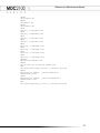
1
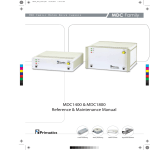
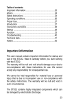
mdc2100_cover_06142006.pdf
6/15/2006
10:15:42 AM
MDC2100
MDC2100 Motor Drive Chassis
S E R I E S
C
M
Y
CM
MY
CY
CMY
K
Reference & Maintenance Manual
(MDC200, MDC400, MDC800)
Linear Positioning
Rotary Positioning
Motion Controls
Engineered Solutions
Reference & Maintenance Manual
32114 Mallard Ave.
PO Box 409
Tangent, OR 97389-0409
U.S.A.
Phone:
Fax:
Toll Free:
Web:
E-mail:
[541] 791-9678
[541] 791-9410
[888] 754-3111
www.primatics.com
[email protected]
MDC2100 Manual
Revision Information
Publication Date
December 2003
April 2005
November 2006
December 2006
Notes
First Release
Updated look & formatting
Manual Maintenance & Pinout Update
Modified Table 7.3
Notice: Any descriptions, drawings, and specifications contained herein are subject to change.
Primatics is not responsible for errors or omissions herein or for incidental damages in connection
with the furnishing or use of this information. This document shall not be reproduced,
photocopied, or duplicated, in whole or in part, without prior written approval of Primatics
Corporation.
For additional specifications, dimensioned drawings and additional information, refer to the
MDC2100 Datasheet available from our website at www.primatics.com.
©Copyright 2007 by Primatics, Inc; All Rights Reserved. Primatics, the Primatics logo, PrimaFlex,
PrimaSeal & SimpleMatch are trademarks of Primatics, Inc.
1
Reference & Maintenance Manual
Manual Revision Information ........................................................... 1
1) Overview......................................................................................... 3
2) Introduction – About the MDC2100 Family................................. 4
3) Model Configuration ..................................................................... 5
4) Personal Safety ............................................................................. 6
5) Installation...................................................................................... 7
5.1) Locating the MDC2100 .............................................................................................................................7
5.2) Front Panel Indicators and Controls..........................................................................................................8
5.3) Rear Panel Information ..............................................................................................................................9
5.3.1) Communication Ports: RS-232, Ethernet ..........................................................................................9
5.3.2) The I/O Port Pinout ...........................................................................................................................10
5.3.3) Auxiliary Encoder Option ................................................................................................................11
5.4) The Safety Port .........................................................................................................................................12
5.4.1) Stop Loop and Stop Switch ..............................................................................................................12
5.5) Axis Information ......................................................................................................................................13
6) Operations.................................................................................... 15
6.1) Fault Detection and Motor Power Control .............................................................................................15
6.2) Motor Output Signals...............................................................................................................................16
6.2.1) Brushless Servo Motor......................................................................................................................16
6.3) Encoder Input ...........................................................................................................................................17
6.4) Limit, Home & Temp Sensors.................................................................................................................18
6.5) Brake Release Output...............................................................................................................................18
7) The Galil DMC Interface .............................................................. 19
7.1) The I / O Port ............................................................................................................................................19
7.2) Overview...................................................................................................................................................19
7.2.1) MDC Digital Inputs and Outputs .....................................................................................................20
7.3) The MDCOptima Application Programming Interface .........................................................................21
7.3.1) The API..............................................................................................................................................21
7.3.2) Motor Power Control ........................................................................................................................21
7.3.3) Brakes ................................................................................................................................................22
7.4) Software Installation ................................................................................................................................23
7.4.1) Set the Controller Parameters...........................................................................................................23
7.4.2) Setting Motion Control Parameters for each axis ...........................................................................23
7.4.3) Loading the API ................................................................................................................................23
7.4.4) Example 1 – Brushless Servo - Trapezoidal Drive .........................................................................23
7.5) Appendices................................................................................................................................................26
7.5.1) Appendix A – MDCOptima API......................................................................................................26
8) Troubleshooting & Service ........................................................ 28
8.1) Troubleshooting Help...............................................................................................................................28
8.2) Service.......................................................................................................................................................28
2
Reference & Maintenance Manual
1) Overview
This user guide is designed to help you install and maintain your MDC Series motion
control. Follow these steps to ensure correct installation and maximum life:
Step 1
Review this entire user manual. Become familiar with all installation procedures
prior to integrating your system.
Step 2
Review the safety summary to develop an understanding of standard safety
practices when installing and operating automated equipment.
Step 3
Review installation procedures. For best results, follow these procedures
carefully.
3
Reference & Maintenance Manual
2) Introduction – About the MDC2100 Family
This manual is intended for use by application engineers and technicians involved with
Primatics positioning equipment.
The MDC2100 is a complete motion
control system in a small package. It
combines a programmable motion
controller (Galil DMC-21x3), servo
drives, power supplies, and all necessary
wiring into a single package. The
MDC2100 is optimized for controlling
Primatics positioning stages and
mechanisms, but can also be used with
third party positioning stages or axes. A
variety of cable assemblies are available
to connect positioning stages or axes to
the MDC. The diagram to the left shows
the role of a MDC in a motion control
system.
The integrated Galil DMC-21x3
programmable motion control card
makes the MDC a powerful element in a
motion control system. The DMC-21x3
can be programmed via its integrated RS-232 or 10BaseT Ethernet connection and
operates as a stand alone system using the Galil’s internal program memory storage
capability. The Galil DMC-21x3 is a multi-tasking, multi-axis, high performance motion
controller. Refer to the Galil DMC-21x3 programming and users manuals for more
information.
4
Reference & Maintenance Manual
3) Model Configuration
5
Reference & Maintenance Manual
4) Personal Safety
Please review before installing your motion system
Observe common industrial safety practices when installing and operating automated
equipment.
o
Have power connections made by qualified personnel.
o
Keep fingers and other items out of any opening in the stage while it is in
operation since injury or damage may result.
o
Provide a safe access route and adequate room for servicing.
o
Perform the recommended periodic maintenance described in this document.
o
Verify that the work envelope is free of obstructions before the positioning stage
is powered.
o
Insure that for servo motors the encoder must be working properly and the
polarity of the encoder needs to match the polarity of the motor before enabling
the servo drive. Improper feedback connections can cause a motor run-away
condition that has the potential to damage the stage and injure an operator.
o
Only trained operators of the positioning stage should be allowed near the work
environment.
o
Identify emergency stop circuits and actuators in the workcell. In an emergency
press the yellow stop button on the drive chassis front panel. This cuts power to
all axes amplifiers.
o
Note the places in the workcell where pinch points occur, and provide adequate
safety clearance or safety curtain.
o
Never operate the motor in a location that could be splashed by water, exposed
to corrosive or flammable gases or is near combustible substances since this
may cause an electric shock, fire or malfunction.
o
Never touch the motor, driver, or peripheral devices when the power is on or
immediately after the power is turned off. The high temperature of these parts
may cause burns.
6
Reference & Maintenance Manual
5) Installation
5.1) Locating the MDC2100
A typical motion system consists of the MDC, axis cables and positioning stages. The
Motion Controller Card is housed inside the MDC. The MDC also includes Motor Drive
Connectors for each axis of travel; these Motor Drive Connectors connect to stages with
axis cables. Figure 5-1 shows a typical system.
Figure 5-1: MDC2100 Motion System
The MDC must be placed in a convenient location for connection to both the PC and your
stages. Access to the front panel controls and the rear panel connectors must be
considered before installation. There are no user serviceable parts in the chassis, but
axis cards and motion control interface cards are “plug-in” assemblies that can be
removed and installed from the rear of the chassis.
7
Reference & Maintenance Manual
Figure 5-2: Dimensions of MDC2100
5.2) Front Panel Indicators and Controls
Figure 5-3: Front Panel
SYSTEM POWER is illuminated whenever power is applied to the chassis, and the
power switch on the rear is turned on.
MOTOR POWER is illuminated when the internal motor power supply is turned on.
FAULT is illuminated whenever any condition exists that prevents the motor power
supply to be turned on.
STOP is connected into the STOP loop described in 5.4.
8
Reference & Maintenance Manual
5.3) Rear Panel Information
All connections to the MDC are made at the rear of the chassis. Connections include AC
power, communications to the DMC-21x3, I/O from the DMC-21x3, and signals for the
attached positioning stages or axes.
Figure 5-4: Galil Communications Connections
5.3.1) Communication Ports: RS-232, Ethernet
Communication to the integrated Galil DMC-21x3 can use either the RS-232 port or
Ethernet port as indicated. The RS-232 port operates at 19.2K. The Ethernet port is a
10BaseT port. Refer to the Galil DMC-21x3 User Manual, Chapter 4 for detailed
information about both of these interfaces. The factory default IP address is
192.168.0.60.
9
Reference & Maintenance Manual
5.3.2) The I/O Port Pinout
The third connector is the I/O connector located on the rear of the MDC chassis. This
port provides access to certain Input, Output, Status, and Control signals from the Galil
motion control card. The pin definition for this port is shown Table 5-1 below.
Please note that many of the signals in the I/O Port are TTL logic levels. Power supply
signals are included in the port for users that want to provide external signal conditioning.
If you want internal signal conditioning for your application, contact the factory.
Table 5-1: I/O Port Pinout:
Connector: DB25S Mate: DB25P
Pin
1
14
2
15
3
16
4
17
5
18
6
19
7
20
8
21
9
22
10
23
11
24
12
25
13
Name
USER IN 1
USER IN 2
USER IN 3
USER IN 4
USER OUT 1
USER OUT 2
USER OUT 3
AIN 1
AIN 2
AIN 3
AIN 4
AIN 5
AIN 6
AIN 7
AIN 8
ABORT
ENC CMP
ERROR
USER OUT 4
NC
+12VDC
-12VDC
GND
GND
5VDC
Description
TTL input
TTL input
TTL input
TTL input
TTL output
TTL output
TTL output
Analog Input 1
Analog Input 2
Analog Input 3
Analog Input 4
Analog Input 5
Analog Input 6
Analog Input 7
Analog Input 8
TTL input. Abort input of Galil card. Active low.
TTL output. Encoder Compare output of Galil card.
TTL output. Error output
TTL output
No connection
Power supply, 12VDC, 150mA max.
Power supply, -12VDC, 100mA max.
DC common for power supplies and signals
see pin 12
Power supply, 5VDC, 200mA max.
10
Reference & Maintenance Manual
5.3.3) Auxiliary Encoder Option
An available option for the MDC2100 is the Auxiliary Encoder Connector. This allows
connection to secondary encoders for dual-loop operation.
Table 5-2: Auxiliary Encoder Pinout:
Connector: DB25S Mate: DB25P
Pin
1
14
2
15
3
16
4
17
5
18
6
19
7
20
8
21
9
22
10
23
11
24
12
25
13
Name
5VDC
DCCOM
AUXA A+
AUXA AAUXA B+
AUXA B5VDC
DCCOM
AUXB A+
AUXB AAUXB B+
AUXB B5VDC
DCCOM
AUXC A+
AUXC AAUXC B+
AUXC B5VDC
DCCOM
AUXD A+
AUXD AAUXD B+
AUXD BCHASSIS
Description
Encoder Power
Power Common
Auxiliary Encoder Axis A, A+
Auxiliary Encoder Axis A, AAuxiliary Encoder Axis A, B+
Auxiliary Encoder Axis A, BEncoder Power
Power Common
Auxiliary Encoder Axis B, A+
Auxiliary Encoder Axis B, AAuxiliary Encoder Axis B, B+
Auxiliary Encoder Axis B, BEncoder Power
Power Common
Auxiliary Encoder Axis C, A+
Auxiliary Encoder Axis C, AAuxiliary Encoder Axis C, B+
Auxiliary Encoder Axis C, BEncoder Power
Power Common
Auxiliary Encoder Axis D, A+
Auxiliary Encoder Axis D, AAuxiliary Encoder Axis D, B+
Auxiliary Encoder Axis D, BChassis Connection
11
Reference & Maintenance Manual
5.4) The Safety Port
At the rear of the MDC chassis is a pluggable terminal strip labeled Safety Port. The
Safety Port provides connection access to two features: the Stop Loop and the Stop
Switch.
5.4.1) Stop Loop and Stop Switch
To enhance the safety of an application, the motor power supply in the MDC uses an
external Stop Loop to control the state of its motor power circuit. For normal operation of
the motor power supply, the Stop Loop found on pins 3 and 4 of the Safety Port must
form a closed circuit. An open Stop Loop will generate internal STOP and hardware
faults, killing power to the motors.
The Stop Switch on the front panel of the MDC chassis is a normally closed switch
connected between pins 1 and 2 of the Safety Port. If no external devices are to be
connected to the Stop Loop, the Stop Switch must be connected as shown in Figure 5-5.
Figure 5-5: Stop Switch and Stop Loop connections (pins 1, 2, 3 and 4 of Safety
Port)
To connect the MDC safety system to external devices, such as an external STOP
switch, light curtain, etc, insert the normally closed circuit from the safety devices into one
of the two loops show in Figure 5-5. Assure that the safety circuit is a dry contact.
12
Reference & Maintenance Manual
5.5) Axis Information
Primatics linear and rotary stages are connected to the MDC chassis using the Servo
Axis Cable accessory. The standard cable is 12 ft. long, but cables up to 50 ft. in length
can be used. Connect the cable from the appropriate axis connector at the rear of the
MDC chassis to the stage. The Axis connectors are associated to Galil axes A through
D. Only those connectors for the ordered configuration are present. For example: a 2axis MDC2100 will have connectors for axes A & B only.
Figure 5-6: Axis Connectors and Galil Association
13
Reference & Maintenance Manual
Table 5-3 shows the pin-out of the Axis connectors.
Table 5-3: Servo Axis Connector Pin-out
Connector: FCI UTG020-S Mate: FCI UTG620-28PN
Pin
A
B
C
D
E
F
G
H
J
K
L
M
N
P
R
S
T
U
V
W
X
Y
Z
a
b
c
d
Name
MOT A
MOT B
MOT C
MOT SHLD
ENC 5V
ENC A+
ENC AENC B+
ENC BENC SHLD
LIMIT 12V
LIMIT COM
HOME
BRAKE+
BRAKESHIELD
HALL V+
HALL VENC VENC I+
ENC IFLS
RLS
not used
HALL A
HALL B
TEMP
e
HALL C
Function
Motor phase A
Motor phase B
Motor phase C
Shield for motor signals, connect to motor case.
Encoder power supply, 5VDC
Encoder channel A+
Encoder channel AEncoder channel B+
Encoder channel BShield for encoder signals, connect to encoder case.
Power supply for limit switches, 12VDC
power supply return for limit switches.
Home signal input
Failsafe brake power output, 24VDC to release brake
return for brake power output
Shield for cable
Limit switch power output, 5VDC
return for limit switch power output
Return for Encoder power
Encoder channel I+
Encoder channel IForward limit switch input. Connect to LIMIT COM for normal operation.
Reverse limit switch input. Connect to LIMIT COM for normal operation.
Hall sensor A input
Hall sensor B input
Motor temperature switch input. Connect to LIMIT COM for normal
operation.
Hall sensor C input
14
Reference & Maintenance Manual
6) Operations
6.1) Fault Detection and Motor Power Control
For the MDC, a fault is any condition that will prevent power from being applied to the
motor drives. There are two DC power systems in the MDC chassis: the Logic supply
and the Motor supply. The Logic supply provides DC power to all internal circuits as well
as externally connected encoders, limit and home sensors, and optional brakes. The
Logic supply is on anytime AC power is supplied and the power switch is on. This
condition is indicated with the illumination of the SYSTEM POWER indicator on the front
panel.
The Motor supply provides the DC power to all of the motor drives. This power supply is
on only if there are no fault conditions, and the motion controller has turned on the supply
through its I/O signals. A fault condition will override the signals from the motion
controller and turn off the motor supply. If a fault condition occurs, the source of the fault
must be removed, and the condition must be re-set using I/O signals from the motion
controller.
A Fault condition is indicated by the illuminated FAULT indicator on the front panel. This
condition is caused when any of the following occur:
•
•
•
System power turn-on
Power Supply Fault
STOP LOOP on SAFETY PORT is open
The state of the Fault as well as the cause of the fault may be determined through input
signals to the motion controller.
15
Reference & Maintenance Manual
6.2) Motor Output Signals
6.2.1) Brushless Servo Motor
The brushless servo motor drives control current through the three phases of a brushless
motor. The motor is commutated with hall sensors. Figure 6-1 shows the timing diagram
for the motor phases and commutation sensors.
Figure 6-1: Motor commutation chart
16
Reference & Maintenance Manual
6.3) Encoder Input
The encoder input is necessary to operate the motor. The encoder inputs are compatible
with RS-422 differential signals commonly used on industrial encoders. Figure 6-2 shows
the timing diagram for the encoder input.
Figure 6-2: Encoder signal timing diagram for positive motion
17
Reference & Maintenance Manual
6.4) Limit, Home & Temp Sensors
The MDC2100 supports monitoring a forward limit, reverse limit, and home sensor for
each axis. Figure 6-3 shows an equivalent schematic for the limit, home, and
temperature inputs. Note that the MDC2100 has a 12V supply available to power
external sensor circuits.
Figure 6-3: Sensor Input Circuit Diagram
6.5) Brake Release Output
Each axis includes a circuit to energize (supply power to) a fail-safe brake. A fail-safe
brake will hold an axis from moving when no power is applied to the brake. The brake
release output will supply 24VDC to a brake when the output is on. The brake release
output is on only when all of these conditions are satisfied:
•
•
•
•
Motor power supply is on
The drive amplifier is enabled by the motion controller
The drive amplifier has no faults
The brake release enable output bit from the motion controller is on
18
Reference & Maintenance Manual
7) The Galil DMC Interface
7.1) The I / O Port
This port provides access to certain Input, Output, Status, and Control signals from the
Galil motion control card. The pin definition for this port is shown in Table 7-1.
Please note that many of the signals in the I/O Port are TTL logic levels. Power supply
signals are included in the port for users that want to provide external signal conditioning.
If you want internal signal conditioning for your application, contact the factory.
Table 7-1) I/O Port Pinout:
Connector: DB25S Mate: DB25P
Pin
1
14
2
15
3
16
4
17
5
18
6
19
7
20
8
21
9
22
10
23
11
24
12
25
13
Name
USER IN 1
USER IN 2
USER IN 3
USER IN 4
USER OUT 1
USER OUT 2
USER OUT 3
ANALOG IN 1
ANALOG IN 2
ANALOG IN 3
ANALOG IN 4
ANALOG IN 5
ANALOG IN 6
ANALOG IN 7
ANALOG IN 8
ABORT
ENC CMP
ERROR
NC
NC
+12VDC
-12VDC
GND
GND
5VDC
Description
TTL input
TTL input
TTL input
TTL input
TTL output
TTL output
TTL output
AIN 1 of Galil card
AIN 2 of Galil card
AIN 3 of Galil card
AIN 4 of Galil card
AIN 5 of Galil card
AIN 6 of Galil card
AIN 7 of Galil card
AIN 8 of Galil card
TTL input. Abort input of Galil card. Active low.
TTL output. Encoder Compare output of Galil card.
TTL output. Error output
No connection
No connection
Power supply, 12VDC, 100mA max.
Power supply, -12VDC, 100mA max.
DC common for power supplies and signals
see pin 12
Power supply, 5VDC, 200mA max.
7.2) Overview
The Galil DMC 21x3 series controllers provide motion control for up to four axes of
motion. Cards that support 1 to 4 axes of motion supply eight inputs and eight outputs.
Output bits 4-8 and input bits 5-8 are dedicated to internal functions leaving 3
uncommitted outputs and 4 uncommitted inputs available to the user through I/O
connector 1.
19
Reference & Maintenance Manual
7.2.1) MDC Digital Inputs and Outputs
Five outputs are dedicated to programmatic operation of the MDC2100. Motor Power
Enable and Reset Faults are used to control the motor power circuit. The Brake
Release Enable is used to enable the release of failsafe brakes.
Table 7-2) Controller Digital Outputs
1
2
3
4
5
6
7
8
MDC 1 Outputs
User Output 1
User Output 2
User Output 3
Unused
MDC1 Motor Power Enable
MDC1 Reset Faults
Unused
MDC1 Brake Release Enable
Table 7-3) Inputs
1
2
3
4
5
6
7
8
MDC 1 Inputs
User Input 1
User Input 2
User Input 3
User Input 4
MDC 1 Motor Power is Off
MDC 1 Hardware Fault
MDC 1 ESTOP Fault
MDC 1 Logic Power Fault
20
Reference & Maintenance Manual
7.3) The MDCOptima Application Programming Interface
7.3.1) The API
The application programming interface (API) for the MDC Optima is a set of programs,
which reside on the controller card. The programs provide motor power control, and
brake control. For each program, a variable with the same name is provided to indicate
routine completion. The program variable is set to 1 when the routine completes
execution. A program running on the PC can set the variable to zero, execute an API
routine and then poll the value of the variable to determine when the routine has finished.
Appendix A contains a program listing.
7.3.2) Motor Power Control
Table 7-4) Motor Power Control Programs
Program
CF
MPOFF
MPON
Description
Clear faults
Turn motor power off
Turn motor power on
The CF program attempts to reset the hardware faults. First the ESTOP fault and logic
power fault latches are reset and then the hardware fault latch is reset. The fault latch
cannot be reset if faults are still active.
The MPOFF program is used to turn off motor power to all axes. It turns off the enable
motor power output, turning motor power off to all motor drivers (amplifiers). In addition,
the Galil motor off (MO) command is issued to all axes. This turns off the amplifier
enable signal and opens the servo loop for each axis.
The MPON program is used to turn motor power on for all axes. First it issues a Galil
motor off command for all axes. This is done so that the actuators will not jump when
motor power is applied. Next, the enable motor power is turned off and then on. If there
are no faults, this action will turn on the motor power relay, providing power to the motor
drivers. The user must then issue the Galil servo here (SH) command to activate the
amplifier enable signal and close the servo loop at the current position for all axes to be
powered up.
Note: The API programs TA, TD, ELA, ELB & DIM1 are not used with the MDC2100
21
Reference & Maintenance Manual
7.3.3) Brakes
Table 7-5) Brake Programs
Program
DBR1
EBR1
TBR1
Description
Disable brake release, drive 1
Enable brake release, drive 1
Tell brake release status, drive 1
Each axis has a failsafe brake circuit. The brake release signal for an axis is activated if
motor power is on, the amplifier is enabled and not faulted, and the brake release is
enabled. The DBR1 program turns off the enable brake release output for the MDC2100,
disabling the brake release for axes A and B. The EBR1program turns on the brake
release output. The TBR1 program is used to obtain the state of the brake release
output. It sets the variable TBR1VAL to 1 if the enable brake release output is on and 0
otherwise.
22
Reference & Maintenance Manual
7.4) Software Installation
This section discusses the steps required to configure motion cards for the Primatics
motor drive chassis and stages. The MDCOptima API is provided on the disk labeled
Primatics MDCOptima API (Part Number 0-6950-0001). One file on the disc contains
motion control parameters, another file contains controller API and utility programs and
another file is called README.TXT and has instructions on how to use the other two
files, configure the motion control card, turn on power, close the servo loop, home the
axes, set the cycle speeds, and start and stop the program. The motion control
parameters used at the factory are supplied with each stage. Some parameters will need
to be modified depending on the particular application (e.g. tuning parameters).
7.4.1) Set the Controller Parameters
Set the BA command to specify which axes require sinusoidal commutation. Use the CN
command to specify the limit switch polarity.
7.4.2) Setting Motion Control Parameters for each axis
Appendix A contains a sample motion control parameters sheet provided with PLG and
PLR series stages. Using the Galil DMC Terminal Program or the Set-up and Configure
Form of the Servo Design Kit enter the motion control parameters. Don’t forget to save
the setting in nonvolatile memory.
7.4.3) Loading the API
To use the API, it must be included with the application code and downloaded to the
motion card. The examples below are in the form of a DMC Terminal program session.
In these terminal sessions, the characters typed by the user are in regular type and the
controller response is in bold italics.
7.4.4) Example 1 – Brushless Servo - Trapezoidal Drive
It is an example of a controller with one brushless servo – trapezoidal drive. The drive is
connected to the A (X) axis. The stage has an encoder ratio of 800 counts/mm and
equipped with a failsafe brake. The following instructions are issued via the DMC
Terminal program:
7.4.4.1) Controller configuration
Instruction
BA
CN 1
Interpretation
All axes are cleared for sinusoidal commutation (The servo driver is of
Trapezoidal type).
Limit switches active high
23
Reference & Maintenance Manual
7.4.4.2) Axis A configuration
Instruction
MTA=1
CEA=0
DVA=0
KDA=20
KPA=4
KIA=1
ILA=2
TLA=9.998
OFA=0
ERA=800
OEA=1
FAA=0
FVA=0
ACA=2400000
DCA=2400000
MO;BN
Interpretation
Motor type is servo
Main encoder and auxiliary encoder are normal quadrature.
Dual loop filter mode is disabled
Derivative constant
Proportional constant
Integrator
Integrator limit
Torque limit
Offset
Error limit
Off on error enabled
Acceleration feedforward
Velocity feedforward
Set acceleration (3000mm/sec)
Set deceleration (3000mm/sec)
Save parameters
7.4.4.3) Preparing the axis to move
Instruction
XQ#CF
XQ#TD
TDVAL=
17.000
XQ#MPON
XQ#TD
TDVAL=
16
SHA
XQ#TA
TAVAL=
30
XQ#EBR1
Interpretation
Clear latched faults
Obtain MDC0200 status
Bit 0 is 1 indicating motor power is off. Bits 1, 2, and 3 are 0 indicating that
there is no hardware, system power or ESTOP faults.
Enable MDC0200 power.
Obtain MDC0200 status
Bit 0 is 0 indicating motor power is on.
Close servo loop
Obtain amplifier status
Bit 0 is 0 indicating the A axis amplifier is OK.
Activate the MDC1 failsafe brake release enable signal. Now, the axis A
failsafe brake will release since motor power is on, the SH command has been
issued, and the amplifier is OK.
24
Reference & Maintenance Manual
7.4.4.4) Home using encoder latching
Instruction
CN,-1
SPA=40000
FEA;BGA
AMA;TPA
-39921
XQ#ELA
SPA=20000
PRA=-8000
BGA
AMA;TPA
-47921
MG _ALA
0.0
RLA
-41239
PAA=_RLA
BGA;AMA
DPA=0
Interpretation
Home switch active low
Set speed to 50mm/sec
Move to the home sensor transition neighborhood
When the motion is complete, report the current position
Route encoder index signal to input 1 and arm latch
Set the move speed (do not exceed 20000 counts/sec)
Setup a relative move of –10mm
Initiate move
When the motion is complete, report the current position
The latch is not armed indicating the encoder index transition was detected.
Report the latched position.
Setup a move to the latched position
Start move and wait for move completion
Define the latched position to be the home position
25
Reference & Maintenance Manual
7.5) Appendices
7.5.1) Appendix A – MDCOptima API
NO ==========================
NO
Primatics, Inc.
NO
MDCOptima API
NO
Version 1.0
NO ==========================
NO -- Terminology
NO MDC0200 Motor Drive Chassis
NO x
Axis A,B,C,D,E,F,G,H
NO d
MDC0200 1,2
NO -- Programs
NO #CF Clear faults, both MDCs
NO #DBRd Turn off brake release enable, MDC0200 d
NO #DIMd Disable input multiplexer MDC0200 d
NO #EBRd Enable brake release MDC0200 d
NO #ELx Enable latching of index pulse x axis
NO #MPOFF Turn motor power off, both MDCs
NO #MPON Turn motor power on, both MDCs
NO #TA Axes amplifier status
NO TAVAL - Bitwise amp status
NO
Bits 0 - 7 = Axes A - H, 1=Faulted
NO #TBRd Tell if brake release enable is on, MDC0200 d
NO TBRdVAL - 1=Enable brake release output is on
NO #TD MDC0200 1 & 2 status
NO TDVAL - Bitwise MDC0200 status
NO
Bits 0-3=MDC1, 4-7=MDC2
NO
Bit
Description
1=
NO
0,4
Motor Power On?
Off
NO
1,5
Hardware Ok?
Faulted
NO
2,6
Logic Power Ok?
Faulted
NO
3,7
ESTOP Ok?
Faulted
NO -- Labels
NO #TBR1A,#TBR2A
NO -- Variables used
NO Completion codes
NO
CF,DBR1,DBR2,DIM1,DIM2,EBR1,EBR2
NO
ELA,ELB,ELC,ELD,ELE,ELF,ELG,ELH
NO
MPOFF,MPON,TA,TBR1,TBR2,TD
NO Status variables
NO
TAVAL, TBR1VAL, TBR2VAL, TDVAL
#CF
CB6;WT100;SB6;WT100;CB14;WT100;SB14;WT100;
CB6;WT100;SB6;WT100;CB14;WT100;SB14;WT100;CF=1;EN
#DBR1
CB8;DBR1=1;EN
#DBR2
CB16;DBR2=1;EN
#DIM1
CB4;DIM1=1;EN
26
Reference & Maintenance Manual
#DIM2
CB12;DIM2=1;EN
#EBR1
SB8;EBR1=1;EN
#EBR2
SB16;EBR2=1;EN
#ELA
SB4;CN,,-1;ALA;ELA=1;EN
#ELB
SB4;CN,,-1;ALB;ELB=1;EN
#ELC
SB4;CN,,-1;ALC;ELC=1;EN
#ELD
SB4;CN,,-1;ALD;ELD=1;EN
#ELE
SB12;CN,,-1;ALE;ELE=1;EN
#ELF
SB12;CN,,-1;ALF;ELF=1;EN
#ELG
SB12;CN,,-1;ALG;ELG=1;EN
#ELH
SB12;CN,,-1;ALH;ELH=1;EN
#MPOFF
MO;CB5;CB13;MPOFF=1;EN
#MPON
MO;CB5;CB13;WT 50;SB5;SB13;MPON=1;EN
#TA
SB7;SB15;TAVAL=@INT[_TI0/16]+(_TI1&$F0);TA=1;EN
#TBR1
TBR1VAL=1;JP #TBR1A, _OP0&128;TBR1VAL=0
#TBR1A;TBR1=1;EN
#TBR2
TBR2VAL=1;JP #TBR2A, _OP0&32768;TBR2VAL=0
#TBR2A;TBR2=1;EN
#TD
CB7;CB15;TDVAL=@INT[_TI0/16]+(_TI1&$F0);TD=1;EN
27
Reference & Maintenance Manual
8) Troubleshooting & Service
8.1) Troubleshooting Help
For further assistance contact the factory:
M-F 8AM to 5PM Pacific Time
Phone:
Fax:
Toll Free:
Web:
E-mail:
[541] 791-9678
[541] 791-9410
[888] 754-3111
www.primatics.com
[email protected]
8.2) Service
Should your device require factory service, contact the factory for a Return Materials
Authorization (RMA). When inquiring about an RMA please have the following
information available:
o Your contact information (name, phone, email, address)
o Unit Serial Number (located on label near the power switch)
o Symptom of problem
o History of troubleshooting steps already taken
28