1
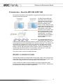
mdc14_1800_cover.pdf
10/30/2006
1:49:32 PM
MDC Family
MDC Family Motor Drive Chassis
S E R I E S
C
M
Y
CM
MY
CY
CMY
K
MDC1400 & MDC1800
Reference & Maintenance Manual
Linear Positioning
Rotary Positioning
Motion Controls
Engineered Solutions
Reference & Maintenance Manual
32114 Mallard Ave.
PO Box 409
Tangent, OR 97389-0409
U.S.A.
Phone:
Fax:
Toll Free:
Web:
E-mail:
[541] 791-9678
[541] 791-9410
[888] 754-3111
www.primatics.com
[email protected]
MDC1400 & MDC1800 Manual
Revision Information
Publication Date
October 2003
July 2004
April 2005
August 2005
January 2006
November 2006
June 2007
October 2007
March 2008
Notes
First Release
Correct Formatting and Typos
Updated Look & Formatting
Correct errors for MDC1800 and I/O
Revised Table 6-4
Updated Chassis Dimensions
Updated Figure 6-5, Added Programming Port Table
Added Motion Control Card connection section
Incorporated Aux Encoders into Section 8.1
Notice: Any descriptions, drawings, and specifications contained herein are subject to change.
Primatics is not responsible for errors or omissions herein or for incidental damages in connection
with the furnishing or use of this information. This document shall not be reproduced,
photocopied, or duplicated, in whole or in part, without prior written approval of Primatics
Corporation.
For additional specifications, dimensioned drawings and additional information, refer to the
MDC1400 & MDC1800 Datasheets available from our website at www.primatics.com.
©Copyright 2007-2008 by Primatics, Inc; All Rights Reserved. Primatics, the Primatics logo,
PrimaFlex, PrimaSeal & SimpleMatch are trademarks of Primatics, Inc.
1
Reference & Maintenance Manual
MDC1400 & MDC1800 Manual Revision Information .................... 1
1) Overview ....................................................................................... 4
2) Introduction – About the MDC1400 & MDC1800........................ 5
3) Model Configuration .................................................................... 6
3.1) MDC1400........................................................................................................................................ 6
3.2) MDC1800........................................................................................................................................ 7
4) Personal Safety
................................................................ 8
5) Installation .................................................................................... 9
5.1) Locating the MDC........................................................................................................................... 9
5.2) Front Panel Indicators and Controls .............................................................................................. 11
5.3) Rear Panel Information ................................................................................................................. 12
5.3.1) The Safety Port........................................................................................................................... 13
6) Connecting Motors to the MDC................................................. 15
6.1) D1 option: Brushless servo motor, trapezoidal drive .................................................................... 16
6.1.1) Brushless Servo Mating Connector Information ........................................................................ 18
6.2) D3 option: Brush servo motor motors ........................................................................................... 19
6.2.1) Brush Servo Mating Connector Information .............................................................................. 21
6.3) D4 option: Step Motor................................................................................................................... 22
6.3.1) Step Mating Connector Information........................................................................................... 26
6.4) D7 option: Brushless motor, digital drive ..................................................................................... 27
6.4.1) Brushless Servo Mating Connector Information ........................................................................ 29
6.5) D9 option: User Axis..................................................................................................................... 30
7) Operations .................................................................................. 31
7.1) Fault Detection and Motor Power Control .................................................................................... 31
7.2) Axis Card Indicators...................................................................................................................... 32
7.3) Motor Output Signals .................................................................................................................... 32
7.3.1) Brushless Servo Motor ............................................................................................................... 32
7.3.2) Step Motor.................................................................................................................................. 33
7.4) Encoder Input ................................................................................................................................ 33
7.5) Limit, Home & Temp Sensors ...................................................................................................... 34
7.6) Brake Release Output.................................................................................................................... 34
8) The Galil DMC 21x3 .................................................................... 35
8.1) DMC 21x3 Connectors for the MDC1400 .................................................................................... 35
8.1.1) Communication Ports: RS-232, Ethernet ................................................................................... 35
8.1.2) The I / O Port.............................................................................................................................. 36
8.1.3) Auxiliary Encoder Input............................................................................................................. 37
8.1.4) External I / O Port (Optional)..................................................................................................... 38
8.2) DMC 21x3 Connectors for the MDC1800 .................................................................................... 39
8.2.1) Communication Ports: RS-232, Ethernet ................................................................................... 39
8.2.2) I / O Ports ................................................................................................................................... 40
8.2.2) Auxiliary Encoder Input............................................................................................................. 42
8.3) Overview ....................................................................................................................................... 44
2
Reference & Maintenance Manual
8.3.1) MDC Digital Inputs and Outputs ............................................................................................... 44
8.3.2) Encoder Index Signals................................................................................................................ 45
8.4) The MDCOptima Application Programming Interface................................................................. 46
8.4.1) The API ...................................................................................................................................... 46
8.4.2) Motor Power Control ................................................................................................................. 46
8.4.3) Brakes......................................................................................................................................... 47
8.4.4) Latching the Encoder Index Pulse.............................................................................................. 48
8.4.5) User Inputs ................................................................................................................................. 48
8.5) Software Installation ..................................................................................................................... 49
8.5.1) Set the Controller Parameters..................................................................................................... 49
8.5.2) Setting Motion Control Parameters for each axis....................................................................... 49
8.5.3) Loading the API ......................................................................................................................... 49
8.5.4) Example 1 – Brushless Servo - Trapezoidal Drive.................................................................... 49
8.6) Appendices.................................................................................................................................... 51
8.6.1) Appendix A – MDCOptima API................................................................................................ 51
9) Troubleshooting & Service........................................................ 54
9.1) Removing a Card........................................................................................................................... 54
9.2) Troubleshooting Help.................................................................................................................... 57
9.3) Service........................................................................................................................................... 57
3
Reference & Maintenance Manual
1) Overview
This user guide is designed to help you install and maintain your MDC Series motion
control. Follow these steps to ensure correct installation and maximum life:
Step 1
Review this entire user manual. Become familiar with all installation procedures
prior to integrating your system.
Step 2
Review the safety summary to develop an understanding of standard safety
practices when installing and operating automated equipment.
Step 3
Review installation procedures. For best results, follow these procedures
carefully.
4
Reference & Maintenance Manual
2) Introduction – About the MDC1400 & MDC1800
This manual is intended for use by application engineers and technicians involved with
Primatics positioning equipment.
The MDC1400 and MDC1800
Series Motor Drive Chassis are
programmable multi-axis motion
controllers. They are modular
system that package motor
drivers, encoder interfaces, power
supplies and safety systems into a
single chassis. A Galil DMC-21x3
Series Motion Control Card is
integrated into the Chassis. Third
party positioning stages or axes
can be operated from a properly
configured MDC. A variety of
cable assemblies are available to
connect a positioning stage or
axis to the MDC.
The integrated Galil DMC-21x3
programmable motion control card
makes the MDC1400/1800 a powerful element in a motion control system. DMC-21x3
can be programmed via its integrated RS-232 or Ethernet connection. The controller can
be operated as a peripheral to the User’s host computer or as a stand alone system
using its internal program memory storage capability. The Galil DMC-21x3 is a multitasking, multi-axis, high performance motion controller. Refer to the Galil DMC-21x3
programming and users manuals for more information. Note that the “x” in the Galil
nomenclature stands for the number of axes available for use.
There are two basic versions of the MDC1400/1800:
MDC1400 for 1 to 4 drive axes in a 3U chassis
MDC1800 for 1 to 8 drive axes in a 6U chassis
The basic MDC models are configured with a motor power supply, motion controller and
motor drives. They can support a mix of servo and stepper drives in one package. Refer
to the Model Configurations on the following pages for more information.
Custom versions of the MDC are also available to meet specific application needs
including versions without an integrated programmable motion controller. Addendums to
this manual will be included for custom configurations.
5
Reference & Maintenance Manual
3) Model Configuration
3.1) MDC1400
6
Reference & Maintenance Manual
3.2) MDC1800
7
Reference & Maintenance Manual
4) Personal Safety
Please review before installing your motion system
Observe common industrial safety practices when installing and operating automated
equipment.
o
Have power connections made by qualified personnel.
o
Keep fingers and other items out of any opening in the stage while it is in
operation since injury or damage may result.
o
Provide a safe access route and adequate room for servicing.
o
Perform the recommended periodic maintenance described in this document.
o
Verify that the work envelope is free of obstructions before the positioning stage
is powered.
o
Insure that for servo motors the encoder must be working properly and the
polarity of the encoder needs to match the polarity of the motor before enabling
the servo drive. Improper feedback connections can cause a motor run-away
condition that has the potential to damage the stage and injure an operator.
o
Only trained operators of the positioning stage should be allowed near the work
environment.
o
Identify emergency stop circuits and actuators in the workcell. In an emergency
press the yellow stop button on the drive chassis front panel. This cuts power to
all axes amplifiers.
o
Note the places in the workcell where pinch points occur, and provide adequate
safety clearance or safety curtain.
o
Never operate the motor in a location that could be splashed by water, exposed
to corrosive or flammable gases or is near combustible substances since this
may cause an electric shock, fire or malfunction.
o
Never touch the motor, driver, or peripheral devices when the power is on or
immediately after the power is turned off. The high temperature of these parts
may cause burns.
8
Reference & Maintenance Manual
5) Installation
5.1) Locating the MDC
A typical motion system consists of the MDC, axis cables and positioning stages. The
Motion Controller Card is housed inside the MDC. The MDC also includes Motor Drive
Cards for each axis of travel; these Motor Drive Cards connect to stages with axis cables.
Figure 5-1 shows a typical system using the MDC1400.
Figure 5-1: MDC1400 Motion System
The MDC must be placed in a convenient location for connection to both the motion
control card and your stages. Access to the front panel controls and the rear panel
connectors must be considered before installation. There are no user serviceable parts in
the chassis, but axis cards are “plug-in” assemblies that can be removed and installed
from the rear of the chassis.
Both desktop and rack mount model dimensions can be found in Figure 5-2. The rack
mount chassis includes mounting flanges for securing the chassis in an equipment rack.
9
Reference & Maintenance Manual
MDC1800
MDC1400
Figure 5-2: Dimensions of MDC
10
Reference & Maintenance Manual
5.2) Front Panel Indicators and Controls
Figure 5-3: Front Panel
SYSTEM POWER is illuminated whenever power is applied to the chassis, and the
power switch on the rear is turned on.
MOTOR POWER is illuminated when the internal motor power supply is turned on.
FAULT is illuminated whenever any condition exists that prevents the motor power
supply to be turned on.
STOP is connected into the Safety Port on the rear panel described in Section 5.3.1.
CB1 is a circuit breaker for the input to the motor power supply.
CB2 is a circuit breaker for the output of the motor power supply.
11
Reference & Maintenance Manual
5.3) Rear Panel Information
All connections to the MDC are made at the Rear Panel. Figures 5-4 and 5-5 show the
Rear Panel views of a typical MDC1400 & MDC1800, respectively. Note that the Motor
Drive Cards (Axis Cards) are identified as Axes 1 through 8. The Galil Motion Controller
will associate the drive card in Axis 1 with Galil Axis A, the drive card in Axis 2 with Galil
Axis B, and so on.
Figure 5-4: Axis Cards and Motion Control Card Association in MDC1400
Figure 5-5: Axis Cards and Motion Control Card Association in MDC1800
12
Reference & Maintenance Manual
5.3.1) The Safety Port
At the rear of the MDC is a pluggable terminal strip labeled Safety Port (see Figure 5-6).
The Safety Port has two functions: connecting the MDC into the safety system of an
application (Stop Loop) and interlocking the safety circuits in multiple MDC systems
(Fault Bus).
Figure 5-6: Safety Port
5.3.1.1) Stop Loop and Stop Switch
To enhance the safety of an application, the motor power supply in the MDC uses an
external Stop Loop to control the state of its motor power circuit. For normal operation of
the motor power supply, the Stop Loop found on pins 3 and 4 of the Safety Port must
form a closed circuit. An open Stop Loop will generate internal STOP and hardware
faults, killing power to the motors.
The Stop Switch on the front panel of the MDC chassis is a normally closed switch
connected between pins 1 and 2 of the Safety Port. If no external devices are to be
connected to the Stop Loop, the Stop Switch must be connected as shown in Figure 5-7.
13
Reference & Maintenance Manual
Figure 5-7: Stop Switch and Stop Loop connections (pins 1, 2, 3 and 4 of Safety
Port)
To connect the MDC safety system to external devices, such as an external STOP
switch, light curtain, etc, insert the normally closed circuit from the safety devices into one
of the two loops show in Figure 5-7. Assure that the safety circuit is a dry contact.
5.3.1.2) Fault Bus
The Fault Bus is used to propagate internal hardware faults from one MDC to another. A
multiple MDC system can use the Fault Bus on pins 5 and 6 of the Safety Port to connect
the safety systems between MDC chassis. In such a system, connect the Fault Buses as
shown in Figure 5-8. When multiple MDCs are connected to the Fault Bus, an ESTOP or
other hardware faults in one MDC will cause a hardware fault in all other MDCs on the
bus. Up to four MDCs can be connected with the Fault Bus. Single MDC systems have
no connection to the Fault Bus.
Figure 5-8: Fault Bus Connections (pins 5 & 6 of Safety Port)
14
Reference & Maintenance Manual
6) Connecting Motors to the MDC
IMPORTANT
ALL CONNECTIONS ARE TO BE MADE WITH NO POWER APPLIED TO THE MDC
This section contains information about all of the drive card options. It includes pin-outs of
the cable connectors on each card as well as specifications. Note that some of the
information may not apply to your specific MDC.
An axis consists of a motor, encoder, forward limit, reverse limit, home sensor, and motor
temperature switch. All servo axes require encoder feedback. For step axes this
feedback is optional.
Different drive options are available for various motor types. Table 6-1 lists the standard
drive options and a description of the drive.
Table 6-1: Drive Options
Option
D1
D3
D4
D7
D9
Drive Type
Brushless Servo,
Trapezoidal
Brushed Servo
Mircrostepping,
Brushless Servo,
Digital Sinusoidal
User Axis
Amps
6A Cont, 12A Peak
Voltage
20-85 V
6A Cont, 12A Peak
5A RMS, 7A Peak
3A Cont, 9A Peak
20-85V
24-75V
20-85V
-
-
Connector
Brushless
Servo
Brush Servo
Stepper
Brushless
Servo
User Axis
Section
6.2
6.3
6.4
6.5
6.6
The following sections describe the connection for the different drive types.
15
Reference & Maintenance Manual
6.1) D1 option: Brushless servo motor, trapezoidal drive
The D1 option is for brushless servo motors that are commutated with hall sensors
(trapezoidal commutation).
Specifications:
Motor Type
Drive Type
Current
Voltage
Min Load Inductance
Bandwidth
Connector
Fuse
Brushless servo with commutation (hall) sensors
PWM. 33 kHz
6A cont / 12A peak
20-80 VDC
200 µH
2.5 kHz
Servo Brushless Axis
6A SB 5x20mm
Figure 6-1) Brushless Motor, Trapezoidal Card
16
Reference & Maintenance Manual
Table 6-2) Brushless Servo Axis Connector Pin-out
Pin
A
B
C
D
E
F
G
H
J
K
L
M
N
P
R
S
T
U
V
W
X
Y
Z
a
b
c
d
e
Name
MOT A
MOT B
MOT C
MOT SHLD
ENC 5V
ENC A+
ENC AENC B+
ENC BENC SHLD
LIMIT 12V
LIMIT COM
HOME
BRAKE+
BRAKESHIELD
HALL 5V
HALL 0V
ENC 0V
ENC I+
ENC IFLS
RLS
<key>
HALL A
HALL B
TEMP
HALL C
Function
Motor phase A
Motor phase B
Motor phase C
Shield for motor signals, connect to motor case.
Encoder power supply, 5VDC
Encoder channel A+
Encoder channel AEncoder channel B+
Encoder channel BShield for encoder signals, connect to encoder case.
12VDC Power supply for home and limit sensors, switchable to 5V
power supply return for home and limit sensors.
Home signal input
Failsafe brake power output, 24VDC to release brake
return for brake power output
Shield for cable
Hall sensor power output, 5VDC
return for Hall sensor power output
Return for Encoder power
Encoder channel I+
Encoder channel IForward limit switch input.
Reverse limit switch input.
Hall sensor A input
Hall sensor B input
Motor temperature switch input. Connect to LIMIT COM for normal operation.
Hall sensor C input
17
Reference & Maintenance Manual
6.1.1) Brushless Servo Mating Connector Information
Connector Parts:
Manufacturer: ITT Cannon. Similar parts also available from FCI:
Description
Connector Body:
Connector Body, cable mount, 28 pins
Backshell
Contacts:
Pins, crimp, 26-24 AWG
Pins, crimp, 22-20 AWG
Pins, crimp, 18-16 AWG
Pins, crimp, 16-14 AWG
Pins, solder cup
Keying pin
Hand Assembly Tools:
Extraction Tool
Crimp Tool, ratcheted
Crimp Tool, low cost, low volume
Cannon P/N
Remark
192922-1290
192922-1350
Mates with panel mount, 28 sockets
Use with any connector body
192990-0020
192990-0040
192990-0060
192990-1240
192900-0632
192990-0000
Use with Crimp Tool
Use with Crimp Tool
Use with Crimp Tool
Use with Crimp Tool
Solder to conductors up to 14 AWG
Use in position ‘a’ for sevo axes
192922-1450
112108-0014
192922-1440
Used with all contacts
Used with crimp contacts 26-16 AWG
Used with crimp contacts 26-14 AWG
Connector Kits:
Kit Model
Connection Kit 28-Position Pin Cable
Connection Tool Kit – Crimp and
Extraction
Remark
Primatics P/N 0-3064-1300 which consists of:
1 cable mount connector body for pins
1 backshell
5 crimp pins 16-18 AWG
30 crimp pins 20-22 AWG
1 keying pin
Primatics P/N 0-3064-1400 which consists of:
1 extraction tool
1 crimp tool (low cost, low volume)
Used with any of the contacts in the kits listed. Only one
kit required per user and tools can be reused on many
connectors
Cable Assemblies:
CABLE-SERVO-MDC-STAGE to connect MDC to Primatics Servo Axis
CABLE-SERVO-MDC-PIGTAIL to connect MDC to User Supplied Servo Axis
18
Reference & Maintenance Manual
6.2) D3 option: Brush servo motor motors
The D3 option is for brush servo motors
Specifications:
Motor Type
Drive Type Current
Current
Voltage
Min Load
Inductance
Bandwidth
Connector
Fuse
Brush DC Servo
PWM. 33 kHz
6A cont / 12A peak
20-80 VDC
200 µH
2.5 kHz
Servo Brushless Axis
6A SB 5x20mm
Figure 6-2) Brush Motor Card
19
Reference & Maintenance Manual
Table 6-3) Brush Servo Axis Connector Pin-out
Pin
A
B
C
D
E
F
G
H
J
K
L
M
N
P
R
S
T
U
V
W
X
Y
Z
a
b
c
d
e
Name
MOT A
MOT B
not used
MOT SHLD
ENC 5V
ENC A+
ENC AENC B+
ENC BENC SHLD
LIMIT 12V
LIMIT COM
HOME
BRAKE+
BRAKESHIELD
not used
not used
ENC 0V
ENC I+
ENC IFLS
RLS
<key>
not used
not used
TEMP
not used
Function
Motor phase A
Motor phase B
Shield for motor signals, connect to motor case.
Encoder power supply, 5VDC
Encoder channel A+
Encoder channel AEncoder channel B+
Encoder channel BShield for encoder signals, connect to encoder case.
12VDC Power supply for home and limit sensors, switchable to 5V
power supply return for home and limit sensors.
Home signal input
Failsafe brake power output, 24VDC to release brake
return for brake power output
Shield for cable
Return for Encoder power
Encoder channel I+
Encoder channel IForward limit switch input. Connect to LIMIT COM for normal operation.
Reverse limit switch input. Connect to LIMIT COM for normal operation.
Motor temperature switch input. Connect to LIMIT COM for normal operation.
20
Reference & Maintenance Manual
6.2.1) Brush Servo Mating Connector Information
Connector Parts:
Manufacturer: ITT Cannon. Similar parts also available from FCI:
Description
Connector Body:
Connector Body, cable mount, 28 pins
Backshell
Contacts:
Pins, crimp, 26-24 AWG
Pins, crimp, 22-20 AWG
Pins, crimp, 18-16 AWG
Pins, crimp, 16-14 AWG
Pins, solder cup
Keying pin
Hand Assembly Tools:
Extraction Tool
Crimp Tool, ratcheted
Crimp Tool, low cost, low volume
Cannon P/N
Remark
192922-1290
192922-1350
Mates with panel mount, 28 sockets
Use with any connector body
192990-0020
192990-0040
192990-0060
192990-1250
192900-0632
192990-0000
Use with Crimp Tool
Use with Crimp Tool
Use with Crimp Tool
Use with Crimp Tool
Solder to conductors up to 14 AWG
Use in position ‘a’ for sevo axes
192922-1450
112108-0014
192992-1440
Used with all contacts
Used with crimp contacts 26-14 AWG
Used with crimp contacts 26-14 AWG
Connector Kits:
Kit Model
Connection Kit 28-Position Pin Cable
Connection Tool Kit – Crimp and
Extraction
Remark
Primatics P/N 0-3064-1300 which consists of:
1 cable mount connector body for pins
1 backshell
5 crimp pins 16-18 AWG
30 crimp pins 20-22 AWG
1 keying pin
Primatics P/N 0-3064-1400 which consists of:
1 extraction tool
1 crimp tool (low cost, low volume)
Used with any of the contacts in the kits listed. Only one
kit required per user and tools can be reused on many
connectors
Cable Assemblies:
CABLE-SERVO-MDC-STAGE to connect MDC to Primatics Servo Axis
CABLE-SERVO-MDC-PIGTAIL to connect MDC to User Supplied Servo Axis
21
Reference & Maintenance Manual
6.3) D4 option: Step Motor
The D4 option is for step motor with encoder axis. There is a protective fuse located as
shown below. The step motor driver can be configured for the number of steps per
revolution of the motor. The configuration is set with a 4 bit DIP switch found on the
motor driver. The motor driver is attached to the Step Driver card with 4 screws shown
below.
Specifications:
Motor Type
Drive Type Current
Current
Voltage
Max Step Freq
Microsteps / Revolution
(1.8º Motor)
Connector
Fuse
2 phase step motor
Microstepping, PWM 20 kHz
1.0 to 7A peak (max 5A RMS)
24 to 75 VDC
1.8 mHz
400, 800, 1000, 1600, 2000, 3200, 5000, 6400,
10000, 12800, 25000, 25600, 50000, 51200
Step Axis Connector
5A SB 5x20mm
Figure 6-3) Microstepping, IMS 805 Stepper Card
22
Reference & Maintenance Manual
Remove the screws and unplug the driver from the card. Turn the driver over and locate
the DIP switch.
Figure 6-4) DIP switch location on driver
The step resolution is set with the switch according to the following table:
Table 6-4) Step Driver Resolution Switch
DIP switch bit
1
2
3
uSteps/Step
uSteps/Rev for
1.8° motor
2
400
4
800
5
1000
8
1600
10
2000
16
3200
25
5000
32
6400
50
10000
64
12800
125
25000
128
25600
250
50000
256
51200
Bold = Factory Default
4
MSEL0
MSEL1
MSEL2
MSEL3
ON
OFF
ON
ON
OFF
OFF
ON
ON
OFF
OFF
ON
ON
OFF
OFF
ON
ON
ON
OFF
ON
OFF
OFF
ON
OFF
ON
ON
OFF
ON
OFF
ON
ON
ON
ON
ON
ON
ON
OFF
ON
OFF
OFF
OFF
OFF
OFF
ON
ON
OFF
ON
OFF
ON
OFF
ON
OFF
ON
OFF
ON
OFF
ON
After the card is configured, re-install the driver onto the card. Verify that the mounting
screws are tight. Install the card into the MDC chassis.
23
Reference & Maintenance Manual
Step Motor Drive Card - Current Adjustment Resistors
The current for the step motor can be adjusted with a resistor on the Step Motor Drive
card. The Drive card also features has a feature to reduce the current when a move is
complete, thus reducing motor and driver heating when no motion is commanded. These
currents are adjusted with two resistors on the board, R2 and R3. Let IRUN = peak
running current and IHOLD = peak holding current. The resistors should have a power
rating of 1/4W (or higher).
Operating Current Adjustment
The value of R2 is set for the desired operating current according to the following
formula:
R2 (Ohms) = IRUN X 500
where IRUN = 1.0A min, 7.0A max
Current Reduction Resistor
The value of R3 is set for the desired holding current according to the following formula:
R3 (Ohms) = 500 X (IRUN x IHOLD) / (IRUN - IHOLD)
where IHOLD = 0.5A min, 7.0A max
Motor Inductance
The Maximum motor inductance (mH per Phase) is determined by
Max Inductance (mH per Phase) = 0.2 x Minimum Supply Voltage
Motors whose inductance exceeds the computed value will have problems moving at
high speed.
24
Reference & Maintenance Manual
Table 6-5) Step Axis Connector Pin-out
Pin
A
B
C
D
E
F
G
H
J
K
L
M
N
P
R
S
T
U
V
W
X
Y
Name
MOT A+
MOT B+
MOT B<key>
ENC 5V
ENC A+
ENC AENC B+
ENC BENC
SHIELD
12VDC
DCCOM
HOME
BRAKE+
BRAKECHASSIS
MOT AMOT B COM
ENC 0V
ENC I+
ENC IFLS
Z
RLS
a
b
c
d
MOT SHLD
MOT A COM
DCCOM
TEMP
e
n/c
Function
Motor phase A+
Motor phase B+
Motor phase B Encoder 5V
Encoder A+
Encoder AEncoder B+
Encoder BEncoder shield
12VDC Power supply for home and limit sensors, switchable to 5V
power supply return for home and limit sensors.
Home input. Connect to DCCOM to activate
Fail-safe brake power output. 24VDC to release brake
Fail-safe brake power return
Chassis ground
Motor phase A Motor Phase B common (no internal connection)
Encoder power return
Encoder Index+
Encoder Index Forward limit switch input. Must be connected to DCCOM for normal
operation
Reverse limit switch input. Must be connected to DCCOM for normal
operation
shield for motor cable
Motor Phase A common (no internal connection)
Power return for temperature sensor
Temperature sensor input. Must be connected to DCCOM for normal
operation
no connection
25
Reference & Maintenance Manual
6.3.1) Step Mating Connector Information
Connector Parts:
Manufacturer: ITT Cannon. Similar parts also available from FCI:
Description
Connector Body:
Connector Body, cable mount, 28 pins
Backshell
Contacts:
Pins, crimp, 26-24 AWG
Pins, crimp, 22-20 AWG
Pins, crimp, 18-16 AWG
Pins, crimp, 16-14 AWG
Pins, solder cup
Keying pin
Hand Assembly Tools:
Extraction Tool
Crimp Tool, ratcheted
Crimp Tool, low cost, low volume
Cannon P/N
Remark
192922-1290
192922-1350
Mates with panel mount, 28 sockets
Use with any connector body
192990-0020
192990-0040
192990-0060
192990-1250
192900-0632
192990-0000
Use with Crimp Tool
Use with Crimp Tool
Use with Crimp Tool
Use with Crimp Tool
Solder to conductors up to 14 AWG
Use in position ‘D’ for stepper axes
192922-1450
112108-0014
192992-1440
Used with all contacts
Used with crimp contacts 26-14 AWG
Used with crimp contacts 26-14 AWG
Connector Kits:
Kit Model
Connection Kit 28-Position Pin Cable
Connection Tool Kit – Crimp and
Extraction
Remark
Primatics P/N 0-3064-1300 which consists of:
1 cable mount connector body for pins
1 backshell
5 crimp pins 16-18 AWG
30 crimp pins 20-22 AWG
1 keying pin
Primatics P/N 0-3064-1400 which consists of:
1 extraction tool
1 crimp tool (low cost, low volume)
Used with any of the contacts in the kits listed. Only one
kit required per user and tools can be reused on many
connectors
Cable Assemblies:
CABLE-STEP-MDC-STAGE to connect MDC to Primatics Step Axis
CABLE-STEP-MDC-PIGTAIL to connect MDC to User Supplied Step Axis
26
Reference & Maintenance Manual
6.4) D7 option: Brushless motor, digital drive
The D7 option is a digital drive for a brushless motor axis. The drive uses the hall
switches and the encoder to sinusoidally commutate the drive. The drive must be
programmed at the factory. There are no user configurable options for this card.
Specifications:
Motor Type
Drive Type Current
Current
Voltage
Bandwidth
Connector
Fuse
Brushless servo with sinusoidal commutation
PWM. 20 kHz
3A cont / 9A peak
20-90VDC
3.0 kHz
Servo Brushless Axis
5A SB 5x20mm
Figure 6-5) Brushless Motor, Digital Drive Card
27
Reference & Maintenance Manual
Table 6-6) Brushless Servo Axis Connector Pin-out
Pin
A
B
C
D
E
F
G
H
J
K
L
M
N
P
R
S
T
U
V
W
X
Y
Z
a
b
c
d
e
Name
MOT A
MOT B
MOT C
MOT SHLD
ENC 5V
ENC A+
ENC AENC B+
ENC BENC SHLD
LIMIT 12V
LIMIT COM
HOME
BRAKE+
BRAKESHIELD
HALL 5V
HALL 0V
ENC 0V
ENC I+
ENC IFLS
RLS
<key>
HALL A
HALL B
TEMP
HALL C
Function
Motor phase A
Motor phase B
Motor phase C
Shield for motor signals, connect to motor case.
Encoder power supply, 5VDC
Encoder channel A+
Encoder channel AEncoder channel B+
Encoder channel BShield for encoder signals, connect to encoder case.
12VDC Power supply for home and limit sensors, switchable to 5V
power supply return for home and limit sensors.
Home signal input
Failsafe brake power output, 24VDC to release brake
return for brake power output
Shield for cable
Hall sensor power output, 5VDC
return for Hall sensor power output
Return for Encoder power
Encoder channel I+
Encoder channel IForward limit switch input.
Reverse limit switch input.
Hall sensor A input
Hall sensor B input
Motor temperature switch input. Connect to LIMIT COM for normal operation.
Hall sensor C input
Table 6-7) Programming Port / Encoder Output
Pin
2
3
5
6
7
8
9
Name
TxD
RxD
COM
A+
AB+
B-
Function
RS232 transmit to Drive
RS232 receive from Drive
RS232 common
Encoder output, channel A+
Encoder output, channel A Encoder output, channel B+
Encoder output, channel B -
28
Reference & Maintenance Manual
6.4.1) Brushless Servo Mating Connector Information
Connector Parts:
Manufacturer: ITT Cannon. Similar parts also available from FCI:
Description
Connector Body:
Connector Body, cable mount, 28 pins
Backshell
Contacts:
Pins, crimp, 26-24 AWG
Pins, crimp, 22-20 AWG
Pins, crimp, 18-16 AWG
Pins, crimp, 16-14 AWG
Pins, solder cup
Keying pin
Hand Assembly Tools:
Extraction Tool
Crimp Tool, ratcheted
Crimp Tool, low cost, low volume
Cannon P/N
Remark
192922-1290
192922-1350
Mates with panel mount, 28 sockets
Use with any connector body
192990-0020
192990-0040
192990-0060
192990-1240
192900-0632
192990-0000
Use with Crimp Tool
Use with Crimp Tool
Use with Crimp Tool
Use with Crimp Tool
Solder to conductors up to 14 AWG
Use in position ‘a’ for sevo axes
192922-1450
112108-0014
192922-1440
Used with all contacts
Used with crimp contacts 26-16 AWG
Used with crimp contacts 26-14 AWG
Connector Kits:
Kit Model
Connection Kit 28-Position Pin Cable
Connection Tool Kit – Crimp and
Extraction
Remark
Primatics P/N 0-3064-1300 which consists of:
1 cable mount connector body for pins
1 backshell
5 crimp pins 16-18 AWG
30 crimp pins 20-22 AWG
1 keying pin
Primatics P/N 0-3064-1400 which consists of:
1 extraction tool
1 crimp tool (low cost, low volume)
Used with any of the contacts in the kits listed. Only one
kit required per user and tools can be reused on many
connectors
Cable Assemblies:
CABLE-SERVO-MDC-STAGE to connect MDC to Primatics Servo Axis
CABLE-SERVO-MDC-PIGTAIL to connect MDC to User Supplied Servo Axis
29
Reference & Maintenance Manual
6.5) D9 option: User Axis
The User Axis card is used in place of an internal motor drive for connecting to an
external drive or encoder. The signals from the attached motion controller are accessible
on the Axis connector in Table 6-6.
Table 6-8) User Axis
Connector: DB25S
Mate: DB25P
Pin
1
2
3
4
5
6
7
8
9
10
11
12
13
14
15
16
17
18
19
20
21
22
23
24
25
Name
ENC 5V
ENC A+
ENC B+
ENC I+
FLS
HOME
CMDI
STEP
GROUND
+ 12V
24V
VMOTOR
CHASSIS
GROUND
ENC AENC BENC IRLS
AMPENA
GND
DIR
BRKREL
GND
24R
VMCOM
Function
Encoder power supply, 5VDC
Encoder channel A+
Encoder channel B+
Encoder channel I+
Forward limit switch input. Connect to LIMIT COM for normal operation
Home signal input
Analog toque command output, -10 to +10V
Step command output for Step Motors
Failsafe brake release return
+12VDC supply for external circuits
24VDC supply for external circuits
Motor supply voltage
Earth ground
ENC 5V ground
Encoder channel AEncoder channel BEncoder channel IReverse limit switch input. Connect to LIMIT COM for normal operation
Amplifier enable output
Reference for analog torque command
Direction command output for step motors
Brake release
Reference for +12VDC supply
Return for 24VDC supply
Return for motor supply voltage
30
Reference & Maintenance Manual
7) Operations
The operation and use of some features of the MDC are dependent on configuration.
The operation of each drive axis is determined by the specific drive option selected.
Similarly, the operation of the motion controller interface is determined by the specific
version selected. However, there are many functions and features that are common to all
versions and configurations including fault detection, motor power control, motor outputs,
and sensor inputs. This section describes those features.
7.1) Fault Detection and Motor Power Control
For the MDC, a fault is any condition that will prevent power from being applied to the
motor drives. There are two DC power systems in the MDC chassis: the Logic supply
and the Motor supply. The Logic supply provides DC power to all internal circuits as well
as externally connected encoders, limit and home sensors, and optional brakes. The
Logic supply is on anytime AC power is supplied and the power switch is on. This
condition is indicated with the illumination of the SYSTEM POWER indicator on the front
panel.
The Motor supply provides the DC power to all of the motor drives. This power supply is
on only if there are no fault conditions, and the motion controller has turned on the supply
through its I/O signals. A fault condition will override the signals from the motion
controller and turn off the motor supply. If a fault condition occurs, the source of the fault
must be removed, and the condition must be re-set using I/O signals from the motion
controller. The specific I/O signals and their operation are further explained in Section 8.
A Fault condition is indicated by the illuminated FAULT indicator on the front panel. This
condition is caused when any of the following occur:
•
•
•
System power turn-on.
STOP LOOP on SAFETY PORT is open.
Temperature switch input on any axis is open.
The state of the Fault as well as the cause of the fault may be determined through input
signals to the motion controller.
31
Reference & Maintenance Manual
7.2) Axis Card Indicators
FORWARD LIMIT illuminated when
Forward Limit Input is closed to DCCOM
REVERSE LIMIT is illuminated when
Reverse Limit Input is closed to DCCOM
HOME SENSOR is illuminated when
Home Input is closed to DCCOM
TEMP SENSOR is illuminated when
Temperature Input is closed to DCCOM
AMP OK is illuminated when Drive is
powered on, enabled, and has no faults.
7.3) Motor Output Signals
7.3.1) Brushless Servo Motor
The brushless servo motor drives control current through the three phases of a brushless
motor. For the D1 drive option, the motor is typically commutated with hall sensors or
special encoder channels for this purpose. Figure 7.1 shows the timing diagram for the
motor phases and commutation sensors.
Figure 7-1: Motor commutation chart
For the D7 digital drive, the motor is initially commutated by the hall sensors, but
ultimately commutated by the encoder. This drive operates the motor in sinusoidal
commutation which provides for smoother operation with lower torque and velocity ripple.
32
Reference & Maintenance Manual
7.3.2) Step Motor
The step motor drive operates 2 phase, 4 wire step motors. Both 6-wire and 8-wire
motors may be used with the drive, but must be connected in a 4 wire fashion. The step
motor drive is capable of micro-stepping the motor up to 256 micro-steps per step.
Figure 7-2 shows the timing of the step motor drive in half-step mode (2 micro-steps per
step).
Figure 7-2: Step motor phase timing diagram for positive motion
7.4) Encoder Input
All drive card options have provision for incremental encoder position input. In the case
of the servo motors, the encoder input is necessary to operate the motor. The use of the
encoder input with the step motor drive is dependent on the configuration of the Galil.
The encoder inputs are compatible with RS-422 differential signals commonly used on
industrial encoders. Figure 7-3 shows the timing diagram for the encoder input.
Figure 7-3: Encoder signal timing diagram for positive motion
33
Reference & Maintenance Manual
7.5) Limit, Home & Temp Sensors
Each MDC compatible motion controller card supports monitoring a forward limit, reverse
limit, and home sensor for each axis. The temperature switch input on each motor drive
card exists to enhance the operational safety of an axis and is monitored by the Fault
detection circuits discussed in Section 7.1. Figure 7-4 shows an equivalent schematic for
the limit, home, and temperature inputs. Note that the MDC has a 12V supply available
to power external sensor circuits.
Figure 7-4: Sensor Input Circuit Diagram
7.6) Brake Release Output
Each drive card includes a circuit to energize (supply power to) a fail-safe brake. A failsafe brake will hold an axis from moving when no power is applied to the brake. The
brake release output will supply 24VDC to a brake when the output is on. The brake
release output is on only when all of these conditions are satisfied:
•
•
•
•
Motor power supply is on
The drive amplifier is enabled by the motion controller
The drive amplifier has no faults
The brake release enable output bit from the motion controller is on
The brake release enable output bit is described in Section 8.
34
Reference & Maintenance Manual
8) The Galil DMC 21x3
8.1) DMC 21x3 Connectors for the MDC1400
8.1.1) Communication Ports: RS-232, Ethernet
Communication to the integrated Galil DMC-21x3 can be via the RS-232 port or Ethernet
port as indicated. The RS-232 port operates at 19.2K. The Ethernet port is a 10BaseT
port. Refer to the Galil DMC-21x2/21x3 User Manual, Chapter 4 for detailed information
about both of these interfaces. The factory default IP address is 192.168.0.10.
Figure 8-1: Galil Communications Connections for MDC1400
35
Reference & Maintenance Manual
8.1.2) The I / O Port
This port provides access to certain Input, Output, Status, and Control signals from the
Galil motion control card. The pin definition for this port is shown in the table below.
Please note that many of the signals in the I/O Port are TTL logic levels. Power supply
signals are included in the port for users that want to provide external signal conditioning.
If you want internal signal conditioning for your application, contact the factory.
Table 8-1a) I/O Port Pinout:
Connector: DB25S
Mate: DB25P
Pin
1
14
2
15
3
16
4
17
5
18
6
19
7
20
8
21
9
22
10
23
11
24
12
25
13
Name
USER IN 1
USER IN 2
USER IN 3
USER IN 4
USER OUT 1
USER OUT 2
USER OUT 3
NC
NC
NC
NC
NC
NC
NC
NC
ABORT
ENC CMP
ERROR
NC
NC
+12VDC
-12VDC
GND
GND
5VDC
Description
TTL input
TTL input
TTL input
TTL input
TTL output
TTL output
TTL output
No Connection
No Connection
No Connection
No Connection
No Connection
No Connection
No Connection
No Connection
TTL input. Abort input of Galil card. Active low.
TTL output. Encoder Compare output of Galil card.
TTL output. Error output
No connection
No connection
Power supply, 12VDC, 100mA max.
Power supply, -12VDC, 100mA max.
DC common for power supplies and signals
see pin 12
Power supply, 5VDC, 200mA max.
36
Reference & Maintenance Manual
8.1.3) Auxiliary Encoder Input
MDC1400 provides an auxiliary encoder input for the DMC-21x3. The pin definition for
these inputs is shown in the Table below.
Table 8-1b) Aux Encoder Input 1 Pinout:
Connector: High-Density DB26S
Mate: HD DB26P
Pin
1
2
3
4
5
6
7
8
9
10
11
12
13
14
15
16
17
18
19
20
21
22
23
24
25
26
Name
ENC 5V
ENC 0V
CHASSIS
ENC 5V
ENC 0V
ENC 5V
ENC 0V
ENC 5V
ENC 0V
ENC AA+
ENC AAENC BA+
ENC BAENC CA+
ENC CACHASSIS
ENC DA+
ENC DAENC AB+
ENC ABENC BB+
ENC BBENC CB+
ENC CBENC DB+
ENC DB-
Description
5V encoder poser supply
Ground for 5V encoder power supply
Chassis to ground encoder shield
5V encoder poser supply
Ground for 5V encoder power supply
5V encoder poser supply
Ground for 5V encoder power supply
5V encoder poser supply
Ground for 5V encoder power supply
Secondary Encoder input A+ for Axis A
Secondary Encoder input A- for Axis A
Secondary Encoder input A+ for Axis B
Secondary Encoder input A- for Axis B
Secondary Encoder input A+ for Axis C
Secondary Encoder input A- for Axis C
Chassis to ground encoder shield
Secondary Encoder input A+ for Axis D
Secondary Encoder input A- for Axis D
Secondary Encoder input B+ for Axis A
Secondary Encoder input B- for Axis A
Secondary Encoder input B+ for Axis B
Secondary Encoder input B- for Axis B
Secondary Encoder input B+ for Axis C
Secondary Encoder input B- for Axis C
Secondary Encoder input B+ for Axis D
Secondary Encoder input B- for Axis D
37
Reference & Maintenance Manual
8.1.4) External I / O Port (Optional)
This optional port provides access to bits 17 through 32 of external I/O provided by the
DMC-21x3 as well as providing power supply signals for users that want to provide
external signal conditioning. The pin definition for this port is shown in the Table below.
Table 8-1c) External I/O Port Pinout:
Connector: DB37S
Mate: DB37P
Pin
1
20
2
21
3
22
4
23
5
24
6
25
7
26
8
27
9
28
10
29
11
30
12
31
13
32
14
33
15
34
16
35
17
36
18
37
19
Name
NC
NC
NC
GND
BIT32
NC
BIT31
GND
BIT30
NC
BIT29
GND
BIT28
NC
BIT27
GND
BIT26
NC
BIT25
GND
BIT24
NC
BIT23
GND
BIT22
NC
BIT21
GND
BIT20
NC
BIT19
GND
BIT18
NC
BIT17
GND
5V
Description
No Connection
No Connection
No Connection
Ground
Digital I/O Bank 3 – Bit 32
No Connection
Digital I/O Bank 3 – Bit 31
Ground
Digital I/O Bank 3 – Bit 30
No Connection
Digital I/O Bank 3 – Bit 29
Ground
Digital I/O Bank 3 – Bit 28
No Connection
Digital I/O Bank 3 – Bit 27
Ground
Digital I/O Bank 3 – Bit 26
No Connection
Digital I/O Bank 3 – Bit 25
Ground
Digital I/O Bank 2 – Bit 24
No Connection
Digital I/O Bank 2 – Bit 23
Ground
Digital I/O Bank 2 – Bit 22
No Connection
Digital I/O Bank 2 – Bit 21
Ground
Digital I/O Bank 2 – Bit 20
No Connection
Digital I/O Bank 2 – Bit 19
Ground
Digital I/O Bank 2 – Bit 18
No Connection
Digital I/O Bank 2 – Bit 17
Ground
No Connection
38
Reference & Maintenance Manual
8.2) DMC 21x3 Connectors for the MDC1800
8.2.1) Communication Ports: RS-232, Ethernet
Communication to the integrated Galil DMC-21x3 can be via the RS-232 port or Ethernet
port as indicated. The RS-232 port operates at 19.2K. The Ethernet port is a 10BaseT
port. Refer to the Galil DMC-21x2/21x3 User Manual, Chapter 4 for detailed information
about both of these interfaces. The factory default IP address is 192.168.0.10.
Figure 8-2: Galil Communications Connections for MDC-1800
39
Reference & Maintenance Manual
8.2.2) I / O Ports
These ports provide access to certain Input, Output, Status, and Control signals from the
Galil motion control card. The pin definition for these ports are shown in the Tables
below.
Please note that many of the signals in the I/O Port are TTL logic levels. Power supply
signals are included in the port for users that want to provide external signal conditioning.
If you want internal signal conditioning for your application, contact the factory.
Table 8-2a) I/O 1 Port Pinout:
Connector: DB25S
Mate: DB25P
Pin
1
14
2
15
3
16
4
17
5
18
6
19
7
20
8
21
9
22
10
23
11
24
12
25
13
Name
USER IN 1
USER IN 2
USER IN 3
USER IN 4
USER OUT 1
USER OUT 2
USER OUT 3
NC
NC
NC
NC
NC
NC
NC
NC
ABORT
ENC CMP
ERROR
NC
NC
+12VDC
-12VDC
GND
GND
5VDC
Description
TTL input
TTL input
TTL input
TTL input
TTL output
TTL output
TTL output
No Connection
No Connection
No Connection
No Connection
No Connection
No Connection
No Connection
No Connection
TTL input. Abort input of Galil card. Active low.
TTL output. Encoder Compare output of Galil card.
TTL output. Error output
No connection
No connection
Power supply, 12VDC, 100mA max.
Power supply, -12VDC, 100mA max.
DC common for power supplies and signals
see pin 12
Power supply, 5VDC, 200mA max.
40
Reference & Maintenance Manual
Table 8-2b) I/O Port 2 Pinout:
Connector: DB25S
Mate: DB25P
Pin
1
14
2
15
3
16
4
17
5
18
6
19
7
20
8
21
9
22
10
23
11
24
12
25
13
Name
USER IN 9
USER IN 10
USER IN 11
USER IN 12
USER OUT 9
USER OUT 10
USER OUT 11
NC
USER OUT 13
USER OUT 14
NC
NC
NC
NC
NC
ABORT
ENC CMP
ERROR
NC
NC
+12VDC
-12VDC
GND
GND
5VDC
Description
TTL input
TTL input
TTL input
TTL input
TTL output
TTL output
TTL output
No Connection
TTL output
TTL output
No Connection
No Connection
No Connection
No Connection
No Connection
TTL input. Abort input of Galil card. Active low.
TTL output. Encoder Compare output of Galil card.
TTL output. Error output
No connection
No connection
Power supply, 12VDC, 100mA max.
Power supply, -12VDC, 100mA max.
DC common for power supplies and signals
see pin 12
Power supply, 5VDC, 200mA max.
41
Reference & Maintenance Manual
8.2.2) Auxiliary Encoder Input
The MDC1800 comes with 2 D-Sub connectors that provides access to the auxiliary
encoder inputs from the Galil motion control card. The pin definition for these inputs is
shown in the Tables below.
Table 8-3a) Aux 1 Pinout:
Connector: High-Density DB26S
Mate: HD DB26P
Pin
1
2
3
4
5
6
7
8
9
10
11
12
13
14
15
16
17
18
19
20
21
22
23
24
25
26
Name
ENC 5V
ENC 0V
CHASSIS
ENC 5V
ENC 0V
ENC 5V
ENC 0V
ENC 5V
ENC 0V
AUX AA+
AUX AAAUX BA+
AUX BAAUX CA+
AUX CACHASSIS
AUX DA+
AUX DAAUX AB+
AUX ABAUX BB+
AUX BBAUX CB+
AUX CBAUX DB+
AUX DB-
Description
5V encoder power supply
Ground for 5V encoder power supply
Chassis to ground encoder shield
5V encoder power supply
Ground for 5V encoder power supply
5V encoder power supply
Ground for 5V encoder power supply
5V encoder power supply
Ground for 5V encoder power supply
Secondary Encoder input A+ for Axis A
Secondary Encoder input A- for Axis A
Secondary Encoder input A+ for Axis B
Secondary Encoder input A- for Axis B
Secondary Encoder input A+ for Axis C
Secondary Encoder input A- for Axis C
Chassis to ground encoder shield
Secondary Encoder input A+ for Axis D
Secondary Encoder input A- for Axis D
Secondary Encoder input B+ for Axis A
Secondary Encoder input B- for Axis A
Secondary Encoder input B+ for Axis B
Secondary Encoder input B- for Axis B
Secondary Encoder input B+ for Axis C
Secondary Encoder input B- for Axis C
Secondary Encoder input B+ for Axis D
Secondary Encoder input B- for Axis D
42
Reference & Maintenance Manual
Table 8-3b) Aux 2 Pinout:
Connector: High-Density DB26S
Mate: HD DB26P
Pin
1
2
3
4
5
6
7
8
9
10
11
12
13
14
15
16
17
18
19
20
21
22
23
24
25
26
Name
ENC 5V
ENC 0V
CHASSIS
ENC 5V
ENC 0V
ENC 5V
ENC 0V
ENC 5V
ENC 0V
AUX EA+
AUX EAAUX FA+
AUX FAAUX GA+
AUX GACHASSIS
AUX HA+
AUX HAAUX EB+
AUX EBAUX FB+
AUX FBAUX GB+
AUX GBAUX HB+
AUX HB-
Description
5V encoder power supply
Ground for 5V encoder power supply
Chassis to ground encoder shield
5V encoder power supply
Ground for 5V encoder power supply
5V encoder power supply
Ground for 5V encoder power supply
5V encoder power supply
Ground for 5V encoder power supply
Secondary Encoder input A+ for Axis E
Secondary Encoder input A- for Axis E
Secondary Encoder input A+ for Axis F
Secondary Encoder input A- for Axis F
Secondary Encoder input A+ for Axis G
Secondary Encoder input A- for Axis G
Chassis to ground encoder shield
Secondary Encoder input A+ for Axis H
Secondary Encoder input A- for Axis H
Secondary Encoder input B+ for Axis E
Secondary Encoder input B- for Axis E
Secondary Encoder input B+ for Axis F
Secondary Encoder input B- for Axis F
Secondary Encoder input B+ for Axis G
Secondary Encoder input B- for Axis G
Secondary Encoder input B+ for Axis H
Secondary Encoder input B- for Axis H
43
Reference & Maintenance Manual
8.3) Overview
The Galil DMC 21x3 series controllers provide motion control for up to eight axes of
motion. Cards that support 1 to 4 axes of motion supply eight inputs and eight outputs.
Cards that provide from 5 to 8 axes of motion supply 16 inputs and 16 outputs. For
controllers of up to four axes, Galil uses XYZW to label axes. For controllers of more
than four axes, the labels ABCDEFGH are used.
An MDC 1400 supports up to four axes of motion. Output bits 4-8 and input bits 5-8 are
dedicated to providing the interface to the MDC, leaving 3 uncommitted outputs and 4
uncommitted inputs available to the user through the I/O Port.
An MDC 1800 supports up to four axes of motion. Output bits 4-8, 12,15, 16 and input
bits 5-8 and 13-16 are dedicated to providing the interface to the MDC, leaving 8
uncommitted outputs and 8 uncommitted inputs available to the user through the I/O Port.
8.3.1) MDC Digital Inputs and Outputs
Five outputs are dedicated to programmatic operation of every MDC1400. Eight outputs
are dedicated to programmatic operation of every MDC1800. Motor Power Enable and
Reset Faults are used to control the motor power circuit. The Brake Release Enable is
used to enable the release of failsafe brakes. The Input Multiplexer routes the encoder
index signals to inputs allowing the user to latch the stage position corresponding to the
encoder index transition. Four dedicated inputs provide MDC1400 status. Eight
dedicated inputs provide MDC1800 status. The Status Multiplexer allows these inputs
to reflect either motor power control circuit status or amplifier status.
Table 8-4) Controller Digital Outputs
1
2
3
4
5
6
7
8
MDC 1400/1800 Outputs
User Output 1
User Output 2
User Output 3
MDC1 Input Multiplexer
MDC1 Motor Power Enable
MDC1 Reset Faults
MDC1 Status Multiplexer
MDC1 Brake Release Enable
9
10
11
12
13
14
15
16
MDC 1800 only Output
User Output 9
User Output 10
User Output 11
MDC 2 Input Multiplexer
User Output 13
User Output 14
MDC 2 Status Multiplexer
MDC 2 Brake Release Enable
The signals routed to the digital inputs are determined by the state of the Input
Multiplexer and Status Multiplexer for each MDC.
44
Reference & Maintenance Manual
Table 8-5) MDC1400 and 1800 Inputs
1
2
3
4
5
6
7
8
MDC 1400/1800 Input Multiplexer Off
User Input 1
User Input 2
User Input 3
User Input 4
MDC 1400/1800 Status Multiplexer Off
MDC 1 Motor Power is Off
MDC 1 Hardware Fault
MDC 1 ESTOP Fault
MDC 1 Logic Power Fault
MDC 1400/1800 Input Multiplexer On
Axis A Encoder Index
Axis B Encoder Index
Axis C Encoder Index
Axis D Encoder Index
MDC 1400/1800 Status Multiplexer On
Axis A Amp Fault
Axis B Amp Fault
Axis C Amp Fault
Axis D Amp Fault
Table 8-6) MDC1800 only Inputs
9
10
11
12
13
14
15
16
MDC 1800 Input Multiplexer Off
User Input 9
User Input 10
User Input 11
User Input 12
MDC 1800 Status Multiplexer Off
MDC 2 Motor Power is Off
MDC 2 Hardware Fault
MDC 2 ESTOP Fault
MDC 2 Logic Power Fault
MDC 1800 Input Multiplexer On
Axis E Encoder Index
Axis F Encoder Index
Axis G Encoder Index
Axis H Encoder Index
MDC 1800 Status Multiplexer On
Axis E Amp Fault
Axis F Amp Fault
Axis G Amp Fault
Axis H Amp Fault
8.3.2) Encoder Index Signals
The DMC 21x3 series of controllers allows position capture by latching. The encoder
position of an axis can be latched based upon a high to low transition of the input signal
corresponding to that axis. Input 1-4 corresponds to axes A-D, and inputs 9-12 (specific
to the MDC1800) correspond to axes E-H. The MDC1400 makes four external input
signals and four encoder index signals accessible via DMC inputs. The MDC1800 makes
eight external input signals and eight encoder index signals accessible via DMC inputs.
An external input signal is one that is connected to the I/O connector. The Input
Multiplexer output selects between these sets of signals.
Note: In order to reliably capture the encoder index signal hi to low transition, the stage
speed should be less than 20000 counts per second.
45
Reference & Maintenance Manual
8.4) The MDCOptima Application Programming Interface
8.4.1) The API
The application programming interface (API) for the MDC Optima is a set of programs,
which reside on the controller card. The API is written for an 8 axis system, but will
operate properly for a system of 4 axis system. Axes 1-4 axis are identified as Drive 1
and axes 5-8 are identified as drive 2 in the following discussions. The programs provide
motor power control, brake control, and the ability to latch encoder index signals for
homing. For each program, a variable with the same name is provided to indicate routine
completion. The program variable is set to 1 when the routine completes execution. A
program running on the PC can set the variable to zero, execute an API routine and then
poll the value of the variable to determine when the routine has finished. Appendix A
contains a program listing.
8.4.2) Motor Power Control
Table 8-7) Motor Power Control Programs
Program
CF
MPOFF
MPON
TA
TD
Description
Clear faults
Turn motor power off
Turn motor power on
Tell amplifier status
Tell drive status
The CF program attempts to reset the hardware faults on all MDCs. First the ESTOP
fault and logic power fault latches are reset and then the hardware fault latches are reset.
The fault latches cannot be reset, if faults are still active.
The MPOFF program is used to turn off motor power to all axes. For each MDC, the
MPOFF program turns off the enable motor power output, turning motor power off to all
motor drivers (amplifiers). In addition, the Galil motor off (MO) command is issued to all
axes. This turns off the amplifier enable signal and opens the servo loop for each axis.
The MPON program is used to turn motor power on for all axes. First it issues a Galil
motor off command for all axes. This is done so that the actuators will not jump when
motor power is applied. Next, the enable motor power is turned off and then on. If there
are no faults, this action will turn on the motor power relay, providing power to the motor
drivers. The user must then issue the Galil servo here (SH) command to activate the
amplifier enable signal and close the servo loop at the current position for all axes to be
powered up.
The TA program reports the state of each amplifier in the variable TAVAL. The status of
axes A-H is represented in Bits 0-7, respectively. A bit value of 0 indicates the amplifier
is Ok. A value of 1 indicates the amplifier is faulted.
46
Reference & Maintenance Manual
The TD program reports the motor power control status bits for all MDCs in the variable
TDVAL.
Table 8-8) TDVAL Drive Status Bits
Bit
0
1
2
3
4
5
6
7
Drive
1
1
1
1
2
2
2
2
Description
Motor Power On?
Hardware Ok?
ESTOP Ok?
Logic Power Ok?
Motor Power On?
Hardware Ok?
ESTOP Ok?
Logic Power Ok?
Bit = 0
On
Ok
Ok
Ok
On
Ok
Ok
Ok
Bit=1
Off
Faulted
Faulted
Faulted
Off
Faulted
Faulted
Faulted
8.4.3) Brakes
Table 8-9) Brake Programs
Program
DBR1
DBR2
EBR1
EBR2
TBR1
TBR2
Description
Disable brake release, drive 1
Disable brake release, drive 2
Enable brake release, drive 1
Enable brake release, drive 2
Tell brake release status, drive 1
Tell brake release status, drive 2
Each axis has a failsafe brake circuit. The brake release signal for an axis is activated if
motor power is on, the amplifier is enabled and not faulted, and the brake release is
enabled. The DBR1 program turn off the enable brake release output for MDC1,
disabling the brake release for axes A-D. The EBR1 program turns on the brake release
output for MDC1. The TBR1 program is used to obtain the state of the brake release
output. It sets the variable TBR1VAL to 1 if the enable brake release output is on and 0
otherwise. The programs DBR2 and EBR2 control the enable brake release signal for
axes E-H. The program TBR2 in conjunction with the variable TBR2VAL reports the
status of the second brake release.
47
Reference & Maintenance Manual
8.4.4) Latching the Encoder Index Pulse
Table 8-10) Encoder Index Latching Programs
Program
ELA
ELB
ELC
ELD
ELE
ELF
ELG
ELH
Description
Enable index pulse latch, A axis
Enable index pulse latch, B axis
Enable index pulse latch, C axis
Enable index pulse latch, D axis
Enable index pulse latch, E axis
Enable index pulse latch, F axis
Enable index pulse latch, G axis
Enable index pulse latch, H axis
The ELA program sets up the controller to latch the position of the axis A when the
encoder index pulse makes a low to high transition. The program turns on the InputMux1
output, routing the index pulses for axes A-D to inputs 1-4 and then arms the latch for
axis A. After the ELA program is executed, the user interrogates the Galil AL command
to determine if the latch has occurred. After the position is latched, the Galil RL
command is used to obtain the latched position. The programs ELB, ELC, and ELD all
are similar, in that they require InputMux1 to be on. The programs ELE, ELF, ELG, and
ELH all are similar, but they require InputMux2 to be on and route the index pulses for
axes E-H to inputs 9-12 and then arms the latch for axis E, F, G or H.
Note: It is not possible to latch a position of axis A-D and simultaneously read user inputs
1-4. The same restriction holds true for axis E-H and user inputs 9-12. To read user
inputs, see the user inputs section below.
8.4.5) User Inputs
Table 8-11) Input Multiplexer Disable Programs
Program
DIM1
DIM2
Description
Disable input multiplex, Drive 1
Disable input multiplex, Drive 2
Description:
The input multiplexer output for drive 1 determines whether axis A-D encoder index
signals or external user inputs 1-4 are multiplexed to user inputs 1-4. The command
DIM1 disables the drive 1 input multiplexer output, causing the external input signals 1-4
to be routed to user inputs 1-4. Similarly, the command DIM2 disables the multiplexer
output for drive 2. This causes the external input signals 9-12 to be routed to user inputs
9-12.
48
Reference & Maintenance Manual
8.5) Software Installation
This section discusses the steps required to configure motion cards for the Primatics
motor drive chassis and stages. The MDCOptima API is provided on the disk labeled
Primatics MDCOptima API (Part Number 0-6950-0001). One file on the disc contains
motion control parameters, another file contains controller API and utility programs and
another file is called README.TXT and has instructions on how to use the other two
files, configure the motion control card, turn on power, close the servo loop, home the
axes, set the cycle speeds, and start and stop the program. The motion control
parameters used at the factory are supplied with each stage. Some parameters will need
to be modified depending on the particular application (e.g. tuning parameters).
8.5.1) Set the Controller Parameters
Set the BA command to specify which axes require sinusoidal commutation. Use the CN
command to specify the limit switch polarity.
8.5.2) Setting Motion Control Parameters for each axis
Appendix A contains a sample motion control parameters sheet provided with PLG and
PLR series stages. Using the Galil DMC Terminal Program or the Set-up and Configure
Form of the Servo Design Kit enter the motion control parameters. Don’t forget to save
the setting in nonvolatile memory.
8.5.3) Loading the API
To use the API, it must be included with the application code and downloaded to the
motion card. The examples below are in the form of a DMC Terminal program session.
In these terminal sessions, the characters typed by the user are in regular type and the
controller response is in bold italics.
8.5.4) Example 1 – Brushless Servo - Trapezoidal Drive
It is an example of a controller with one brushless servo – trapezoidal drive. The drive is
connected to the A (X) axis. The stage has an encoder ratio of 800 counts/mm and
equipped with a failsafe brake. The following instructions are issued via the DMC
Terminal program:
49
Reference & Maintenance Manual
8.12) Controller configuration
Instruction
BA
CN 1
Interpretation
All axes are cleared for sinusoidal commutation (The servo driver is of
Trapezoidal type).
Limit switches active high
8.13) Axis A configuration
Instruction
MTA=1
CEA=0
DVA=0
KDA=20
KPA=4
KIA=1
ILA=2
TLA=9.998
OFA=0
ERA=800
OEA=1
FAA=0
FVA=0
ACA=2400000
DCA=2400000
MO;BN
Interpretation
Motor type is servo
Main encoder and auxiliary encoder are normal quadrature.
Dual loop filter mode is disabled
Derivative constant
Proportional constant
Integrator
Integrator limit
Torque limit
Offset
Error limit
Off on error enabled
Acceleration feedforward
Velocity feedforward
Set acceleration (3000mm/sec)
Set deceleration (3000mm/sec)
Save parameters
8.14) Preparing the axis to move
Instruction
XQ#CF
XQ#TD
TDVAL=
17.000
XQ#MPON
XQ#TD
TDVAL=
16
SHA
XQ#TA
TAVAL=
30
XQ#EBR1
Interpretation
Clear latched faults
Obtain MDC0200 status
Bit 0 is 1 indicating motor power is off. Bits 1, 2, and 3 are 0 indicating that
there is no hardware, system power or ESTOP faults.
Enable MDC0200 power.
Obtain MDC0200 status
Bit 0 is 0 indicating motor power is on.
Close servo loop
Obtain amplifier status
Bit 0 is 0 indicating the A axis amplifier is OK.
Activate the MDC1 failsafe brake release enable signal. Now, the axis A
failsafe brake will release since motor power is on, the SH command has been
issued, and the amplifier is OK.
50
Reference & Maintenance Manual
8.15) Home using encoder latching
Instruction
CN,-1
SPA=40000
FEA;BGA
AMA;TPA
-39921
XQ#ELA
SPA=20000
PRA=-8000
BGA
AMA;TPA
-47921
MG _ALA
0.0
RLA
-41239
PAA=_RLA
BGA;AMA
DPA=0
Interpretation
Home switch active low
Set speed to 50mm/sec
Move to the home sensor transition neighborhood
When the motion is complete, report the current position
Route encoder index signal to input 1 and arm latch
Set the move speed (do not exceed 20000 counts/sec)
Setup a relative move of –10mm
Initiate move
When the motion is complete, report the current position
The latch is not armed indicating the encoder index transition was detected.
Report the latched position.
Setup a move to the latched position
Start move and wait for move completion
Define the latched position to be the home position
8.6) Appendices
8.6.1) Appendix A – MDCOptima API
NO
NO
NO
NO
NO
NO
NO
NO
NO
NO
NO
NO
NO
NO
NO
NO
NO
NO
NO
NO
NO
==========================
Primatics, Inc.
MDCOptima API
Version 1.0
==========================
-- Terminology
MDC0200 Motor Drive Chassis
x
Axis A,B,C,D,E,F,G,H
d
MDC0200 1,2
-- Programs
#CF Clear faults, both MDCs
#DBRd Turn off brake release enable, MDC0200 d
#DIMd Disable input multiplexer MDC0200 d
#EBRd Enable brake release MDC0200 d
#ELx Enable latching of index pulse x axis
#MPOFF Turn motor power off, both MDCs
#MPON Turn motor power on, both MDCs
#TA Axes amplifier status
TAVAL - Bitwise amp status
Bits 0 - 7 = Axes A - H, 1=Faulted
#TBRd Tell if brake release enable is on, MDC0200 d
51
Reference & Maintenance Manual
NO TBRdVAL - 1=Enable brake release output is on
NO #TD MDC0200 1 & 2 status
NO TDVAL - Bitwise MDC0200 status
NO
Bits 0-3=MDC1, 4-7=MDC2
NO
Bit
Description
1=
NO
0,4
Motor Power On?
Off
NO
1,5
Hardware Ok?
Faulted
NO
2,6
Logic Power Ok?
Faulted
NO
3,7
ESTOP Ok?
Faulted
NO -- Labels
NO #TBR1A,#TBR2A
NO -- Variables used
NO Completion codes
NO
CF,DBR1,DBR2,DIM1,DIM2,EBR1,EBR2
NO
ELA,ELB,ELC,ELD,ELE,ELF,ELG,ELH
NO
MPOFF,MPON,TA,TBR1,TBR2,TD
NO Status variables
NO
TAVAL, TBR1VAL, TBR2VAL, TDVAL
#CF
CB6;WT100;SB6;WT100;CB14;WT100;SB14;WT100;
CB6;WT100;SB6;WT100;CB14;WT100;SB14;WT100;CF=1;EN
#DBR1
CB8;DBR1=1;EN
#DBR2
CB16;DBR2=1;EN
#DIM1
CB4;DIM1=1;EN
#DIM2
CB12;DIM2=1;EN
#EBR1
SB8;EBR1=1;EN
#EBR2
SB16;EBR2=1;EN
#ELA
SB4;CN,,-1;ALA;ELA=1;EN
#ELB
SB4;CN,,-1;ALB;ELB=1;EN
#ELC
SB4;CN,,-1;ALC;ELC=1;EN
#ELD
SB4;CN,,-1;ALD;ELD=1;EN
#ELE
SB12;CN,,-1;ALE;ELE=1;EN
#ELF
SB12;CN,,-1;ALF;ELF=1;EN
#ELG
SB12;CN,,-1;ALG;ELG=1;EN
#ELH
SB12;CN,,-1;ALH;ELH=1;EN
#MPOFF
MO;CB5;CB13;MPOFF=1;EN
#MPON
MO;CB5;CB13;WT 50;SB5;SB13;MPON=1;EN
#TA
52
Reference & Maintenance Manual
SB7;SB15;TAVAL=@INT[_TI0/16]+(_TI1&$F0);TA=1;EN
#TBR1
TBR1VAL=1;JP #TBR1A, _OP0&128;TBR1VAL=0
#TBR1A;TBR1=1;EN
#TBR2
TBR2VAL=1;JP #TBR2A, _OP0&32768;TBR2VAL=0
#TBR2A;TBR2=1;EN
#TD
CB7;CB15;TDVAL=@INT[_TI0/16]+(_TI1&$F0);TD=1;EN
53
Reference & Maintenance Manual
9) Troubleshooting & Service
9.1) Removing a Card
Step 1) Use a small blade screwdriver to loosen each screw in all four corners of the
card. Note that these screws are captive screws and can not be pulled out all the way.
Figure 11-1
54
Reference & Maintenance Manual
Step 2) Pull the card out by the handle as shown in Figure 5-11.
Figure 9-2
Step 3) To insert a new card, line up the PCB with the grooves found in the plastic
guides. The plastic guides are outlined in Figure 5-12.
Figure 9-3
55
Reference & Maintenance Manual
Step 4) The card should slide in with no resistance, but it should be securely within the
grooves of each guide. Push the card firmly to seat it into the backplane. The cover panel
will be flush with the case and other cards.
Figure 9-4
Step 5) Once in place, secure the four retaining screws.
Figure 9-5
56
Reference & Maintenance Manual
9.2) Troubleshooting Help
For further assistance contact the factory:
M-F 8AM to 5PM Pacific Time
Phone:
Fax:
Toll Free:
Web:
E-mail:
[541] 791-9678
[541] 791-9410
[888] 754-3111
www.primatics.com
[email protected]
9.3) Service
Should your device require factory service, contact the factory for a Return Materials
Authorization (RMA). When inquiring about an RMA please have the following
information available:
o Your contact information (name, phone, email, address)
o Unit Serial Number (located on label near the power switch)
o Symptom of problem
o History of troubleshooting steps already taken
57