1
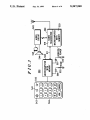
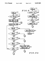
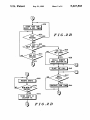
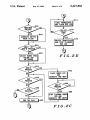
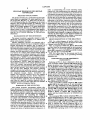
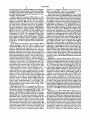
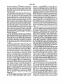
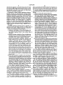
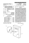
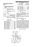
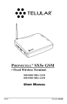
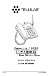
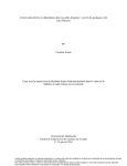
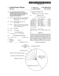
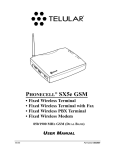
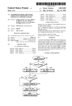
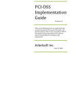
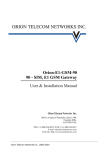
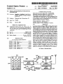
US005247565A
United States Patent [191
[11] Patent Number:
Joglekar et a1.
[45]
[54] CELLULAR TELEPHONE WITH KEYPAD
CONTROLLER
[75] Inventors: Manohar A. Joglekar, Long Grove;
Philip F. Aseltine, Arlington Heights,
Date of Patent:
5,247,565
Sep. 21, 1993
OTHER PUBLICATIONS
Motorola Instruction Manual N0. lS-SP134682.
Motorola Instruction Manual No. 68P81071E30.
The Celjack Owners Manual by Telular Inc.
“Description and Speci?cation GNTA Payphone Type
both of I11.
AY4 (NMT) for Connection to a Mobile Radiostation
[73] Assignee: Motorola, Inc., Schaumburg, Ill.
in Accordancerwith the Speci?cations for the Nordic
Mobile Telephone Systems (NMT)”.
[21] App]. N0.: 779,787
Primary Examiner-James L. Dwyer
[22] Filed:
Assistant Examiner-M. Shehata
Attorney, Agent, or Firm—Kenneth W. Bolvin
[63]
Oct. 21, 1991
Related U.S. Application Data
Continuation-impart of Ser. No. 622,201, Nov. 27,
1990, Pat. No. 5,117,450, which is a continuation of
Ser. No. 369,419, Jun. 20, 1989, abandoned, which is a
continuation-in-part of Ser. No. 349,619, May 10, 1989,
abandoned.
[51]
Int. Cl.5 .......................................... “1104M 11/00
[52]
U.S. Cl. ...................................... .. 379/58; 379/63;
[58]
Field of Search ..................... .. 579/58, 59, 60, 61,
7 379/355
579/63, 355, 356
[56]
References Cited
U.S. PATENT DOCUMENTS
4,658,096
4,718,080
4/1987
1/1988
4,737,975
4,745,632
4,775,997
4,972,459
5,086,452
4/1988
5/1988
10/1988
11/1990
2/1992
5,148,471
5,117,450
West, Jr. ............................. .. 379/59
Serrano etal. ..................... .. 379/59
9/1992
5/1992 Metroka et a1. .................... .. 379/58
541
'
co (3 a)
troller (504) for controlling the operating modes thereof
and automatically placing and receiving cellular tele
phone calls dialed in any pattern. The keypad includes
numerical keys (0-9, # and ") and function keys (MEM
and END/CLEAR) for entering digits of telephone
number and key sequences for selecting operating
modes. Power is applied to the cellular telephone trans
ceiver (519) in response to concurrent activation of at
least two keys. Each telephone number digit is detected
and accumulated by microcomputer (508) and, after a
pause of four seconds, the accumulated digits are sent
via a data bus (511) to cellular telephone transceiver
(519) for placing a telephone call. The call is subse
quently terminated when the END key is activated or
an END command is received by the cellular telephone
transceiver (519). Thereafter, power to the cellular
telephone transceiver (519) may be turned off in re
sponse to activation of the MEM-END key sequence.
15 Claims, 4 Drawing Sheets
AUDIO
CIRCUIT
-
E) G) E)
cellular telephone transceiver (519), and keypad con
,
sat-g 3g 8 5> 542
®®®
O
[57]
ABSTRACT
A unique cellular telephone (500) includes audio circuit
502, microcomputer (508), indicators (506) and (507),
“500
mcaocowurra
WITH
RADIO
TRANSCEIVER
NICROCOMPUTER
WITH
MEMORY
529
US. Patent
Sep. 21, 1993
Sheet 1 of 4
/29:.
m52 : ugzoi :52“;
mugzoci >zowz
:23
:5;
3“n
5,247,565
US. Patent
Sep. 21, 1993
Sheet 2 of 4
5,247,565
‘TURN POWER on mo
was emu LED on
GENERATE DIAL TONE
608
610
MEN-END
YES
PREgSED
TURN POWER OFF
NO
on d N
616
MEN-I
YES
mssco
?
NO
6
618
NEH-5
PRESSED
?
NO
YES
U
620
MEI~0
PREgSED
YES
N0
No
DIG"
624
RECALL NUMBER FROM
SCRATCH PAD AND
0mm: BEEP
622
Pnsgsco
YES
a
A
u
,
FIG.2A
US. Patent
Sep. 21, 1993
Sheet 3 of 4
636
s25
STORE men mo
RESET 4 sm. TIMER
630
YES
N0
4 SR.
_
652
TIMER ngEo our
YES
N0
‘
NO
634
NO
YES
YES
RECALL NUMBER
FROM LOCATION XX
538
PLACE THE CALL
640
'
642
NO
YES
W m
US. Patent
Sep. 21, 1993
5,247,565
Sheet 4 of 4
LOCK TRANSCEIVER
AND FLASH RED LED
NO
NO
YE 5
OENERATE SWITCH
HOOK FLASH
s 48
7
UNLOCK
co?oc
UNLOCK TRANSCEIVER
AND STOP FLASHING
RED LEO
650
Maw 0R
N0
MEN-I gncsszn
.
6 52
YES
ADJUST HANDS FREE
VOLUNE UP‘
FIG.2E
OR DOWNI
.
662
?
NO
END
FLASH GREEN LED
AND
GENERATE ONE BEEP
656
YES
PRESSED
66,4
NEH-6
No.
PRESSED
'1’
YES
655
TOP FLASHING CREE
LED AND
ENERATE
TWO BEEPS
6
NO
NO
END
RECEfIVED
YES
END THE CALL
678
660
FIG.2C
5,247,565
1
2
select a corresponding one of the operating modes,
respectively, the predetermined key sequences includ
CELLULAR TELEPHONE WITH KEYPAD
CONTROLLER
ing the memory key and another key, the second mi
crocomputer storing each received digit in the memory,
and the second microcomputer further being coupled to
the ?rst port of the data bus for automatically transmit
'
RELATED APPLICATIONS
The present invention is a continuation-in-part appli
cation based on copending U.S. patent application Ser.
No. 07/622,201, ?led Nov. 27, 1990, now US. Pat. No.
5,117,450 issued on May 26, 1992 assigned to the instant
ting the stored digits or the selected one of the operat
ing modes to the cellular transceiver when the elapsed
time from detection of the last activated key exceeds a
predetermined time interval; and the ?rst microcom
puter coupled to the second port of the data bus for
receiving the transmitted one of the operating modes
and applying the received operating mode to the cellu
assignee, and incorporated herein by reference. US.
patent application Ser. No. 07/622,201 is a continuation
based on the instant assignee’s US. patent application
Ser. No. 07/369,419, ?led Jun. 20, 1989 and now aban
doned, which in turn is a continuation-in-part applica
tion based on the instant assignee’s US. patent applica
tion Ser. No. 07/349,619, ?led May 10, 1989 and now
lar transceiver, and receiving the transmitted digits and
automatically transmitting the received digits on one of
the cellular radio channels to originate a telephone call,
whereby all dialed digits of each telephone number are
abandoned.
automatically transmitted when dialing is interrupted
BACKGROUND OF THE INVENTION
for at least the predetermined time interval.
The present invention is generally related to radio 20
BRIEF DESCRIPTION OF THE DRAWINGS
telephones, and more particularly to a cellular tele
phone with a keypad controller.
FIG. 1 is a block diagram of another cellular tele
Cellular telephones currently are operated with a
phone 500 embodying the present invention, into which
special purpose handset having an integrated display,
a keypad controller 504' may be plugged.
keypad, microphone and speaker, that is coupled via
25
audio and data buses to a cellular telephone transceiver.
Such special purpose handsets may not be miniaturized
FIG. 2, comprised of FIGS. 2A, 2B, 2C, 2D and 2E,
is a flow chart for the process used by microcomputer
508 in FIG. 1 for control and operation of cellular tele
phone 500 in response to the MEM key, END/CLEAR
due to the integrated display, keypad, microphone and
speaker, and their associated control circuitry. In order
to avoid use of a cellular radio channel during dialing 30
and minimize costs of cellular telephone calls, cellular
key, and digit keys of controller 504.
FIG. 3 is a ?ow chart for the process used by mi
crocomputer 508 in FIG. 1 for processing incoming
telephone users are required to dial a telephone number
telephone calls.
and then press a “SEND” button (pre-origination dial
ing), in order to place a cellular telephone call. Pressing
DESCRIPTION OF THE PREFERRED
the “SEND” button causes the cellular telephone hand 35
EMBODIMENT
set to generate a “SEND” signal and append it to the
Referring to FIG. 1, there is illustrated a block dia
dialed digits transmitted to the cellular telephone trans
ceiver. In contrast, conventional landline telephones
place telephone calls automatically after a pause in dial
ing of several seconds. Such special purpose handsets
also provide many different user features requiring
complex software and additional circuitry. Thus, such
40
gram of another cellular telephone 500 embodying the
present invention, into which a keypad controller 504
may be plugged. Cellular telephone 500 includes audio
circuit 502, microcomputer 508, indicators 506 and 507,
and cellular telephone transceiver 509. Note, however,
special purpose handsets are both relatively large due to
that cellular telephone 500 does not include an informa
ity of keys including ten numerical keys for entering
MEM and END/CLEAR in controller 504, as well as
tion display as is typical of conventional cellular tele
the integrated keypad, display, microphone and
speaker, and relatively expensive due to the complex 45 phones, such as the cellular telephone. By utilizing the
present invention, the need for an information display
software and additional circuitry therein. Moreover,
has been eliminated since cellular telephone 500 may be
such special purpose handset does not operate like con
operated and controlled solely by utilizing controller
ventional landline telephones. For the foregoing rea
504 and its numerical keys 0-9, # and ' and function
sons, there is a need for a cellular telephone with an
inexpensive keypad controller which does not include a 50 keys MEM and END/CLEAR.
Audio circuit 502 of cellular telephone 500 couples
“SEND” button and integrated display.
speaker 544 to the radio receiver of, and microphone
SUMMARY OF THE INVENTION
545 to the radio transmitter of, radio transceiver 519.
Microphone 545 is preferably disposed behind grill-type
The present invention encompasses cellular tele
openings
543 in controller 504. Speaker S44 is not dis
55
phone apparatus having a plurality of operating modes
posed in controller 504. Since controller 504 does not
and being operable on cellular radio channels, the cellu
include a display or speaker 544, controller 504 is
lar telephone apparatus comprising: a data bus having
smaller and less‘ complex than prior art telephone-type
?rst and second ports; a cellular transceiver including a
handsets.
?rst microcomputer for controlling the operating
Microcomputer 508 of cellular telephone 500 is cou
modes and communicating cellular telephone calls on
pled
to numerical keys 0-9, # and * and to function keys
the cellular radio channels; a controller having a plural
to LED indicators 506 and 507 and their corresponding
resistors 532 and 533. LED indicator 506 is lit in white
controlling the operating modes of the radiotelephone;
a second microcomputer including a memory and cou 65 color to indicate that cellular telephone 500 is in a
ROAM operating mode, and LED indicator 507 is lit in
pled to the controller for detecting activations of indiv
red color to indicate that cellular telephone 500 is in the
dual keys to receive telephone number digits and con
NO SERVICE operating mode or is lit in green color
current activations of predetermined key sequences to
telephone numbers and including a memory key for
3
5,247,565
to indicate that cellular telephone 500 is in the POWER
ON and HOME operating modes. LED indicator 506 is
4
response to concurrent activation of any two keys.
Next, at block 608, a dial tone is generated by mi
crocomputer 508 and applied to speaker 544.
preferably positioned in opening 542 in controller 504,
and LED indicator 507 is preferably positioned in open
ing 541 in controller 504.
Proceeding to decision block 610 in FIG. 2A, a check
is made to determine if a MEM-END key sequence has
been pressed. If so, YES branch is taken to block 612,
Cellular telephone transceiver 509 includes a radio
transceiver 519 and microcomputer 529 with memory
where microcomputer 508 turns power off, and thereaf
therein for controlling the operation thereof. Cellular
ter program control returns to other tasks at block 614.
According to a feature of the present invention, power
telephone transceiver 509 may be any conventional
cellular telephone transceiver having a radio transmit
ter, radio receiver and logic unit, such as, for example,
the conventional transceiver shown and described in
Motorola instruction manual number 68P81066E40,
entitled “DYNATAC Cellular Mobile Telephone 800
is turned on in response to concurrent activation of the
MEM-END key sequence. If a MEM~END key se
quence has not been pressed, N0 branch is taken from
decision block 610 to decision block 616, where a check
is made to determine if a MEM-# key sequence has
MHZ Transceiver,” published by and available from
Motorola C & E Parts, 1313 East Algonquin Road,
Schaumburg, Ill. 60196. The operating modes of such
been pressed. According to a feature of the present
invention, the telephone-number store mode is entered
in response to concurrent activation of the MEM-# key
conventional transceiver are described in Motorola
sequence. If the MEM-# key sequence has been
pressed, YES branch is taken from decision block 616 to
user’s manual number 68P8lll6E58, entitled “DYNA
TAC 6800XL Cellular Mobile Telephone USER’S 20 exit point G to FIG. 2D, where, at block 668, mi
crocomputer 508 receives each activated key as digits
MANUAL,” published by and available from Motorola
of a telephone number. Next, at decision block 670 in
C & E Parts, 1313 East Algonquin Road, Schaumburg,
FIG. 2D, a chick is made to determine if a MEM
Ill. 60196.
MEM-XX key sequence has been pressed, where XX
In the preferred embodiment, microcomputer 529 of
cellular telephone transceiver 509 is coupled to mi 25 represents two numerical keys 0-9. If not, NO branch is
taken back to block 668 to receive another digit. If a
crocomputer 508 by way of a three~wire data bus 511,
MEM-MEM-XX key sequence has been pressed, YES
which is illustrated and described in US. Pat. No.
branch is taken from decision block 670 to block 672,
4,369,516. Microcomputer 508 continuously looks for
where the previously received digits are stored as a
activated numerical and functions keys of controller
504. Each telephone number digit corresponding to an 30 telephone number in the memory of microcomputer 508
at location XX. Thereafter program control exits at
activated numerical key is detected and accumulated by
microcomputer 508 in its memory. After a pause of four
seconds, the accumulated digits are coded as described
in the aforementioned US. Pat. No. 4,369,516 and trans
mitted by microcomputer 508 together with a SEND
point B to return to block 608 and continue as described
hereinabove.
-
Returning to decision block 616 in FIG. 2A, if a
35
MEM-# key sequence has not been pressed, NO branch
command via bus 511 to microcomputer 529. Mi
crocomputer 529 receives the dialed digits from bus 511
and encodes and transmits them via the cellular radio
channels by means of the radio transmitter of radio
transceiver 519 for placing a cellular telephone call.
Key sequences of two or more concurrently acti
vated function keys and/or numerical keys are also
where, at block 674, microcomputer 508 electronically
locks cellular telephone transceiver 509 and ?ashes red
detected by microcomputer 508 for selecting operating
telephone transceiver 509 is electronically locked in
is taken to decision block 618, where a check is made to
determine if a MEM-5 key sequence has been pressed. If
so, YES branch is is taken to exit point H to FIG. 2E,
LED indicator 506. According to a feature of the pres
ent invention, the lock mode is entered where cellular
response to concurrent activation of the MEM-5 key
modes of cellular telephone 500. The detected key se
quences are coded into corresponding commands and 45 sequence. Next, at decision block 676 in FIG. 2E, a
check is made to determine if a three-key unlock se
transmitted via bus 511 to microcomputer 529. The
operating modes of cellular telephone 500 include the
quence has been pressed. If not, NO branch is taken
back to block 674 to continue ?ashing red LED indica
power-on mode, power~off mode, telephone-number
tor 506. If the proper three-key unlock sequence has
re-dial mode, telephone-number re-call mode, tele
been pressed, YES branch is taken to block 678, where
phone-number store mode, lock mode, DTMF mode,
hookswitch-?ash mode, speaker-volume adjust mode,
and call-privacy mode.
Referring next to FIG. 2, comprised of FIGS. 2A,
2B, 2C, 2D and 2E, there is illustrated a ?ow chart for
the process used by microcomputer 508 in FIG. 1 for
control and operation of cellular telephone 500 in re
sponse to the MEM key, END/CLEAR key, and nu
merical keys of controller 504. Entering at START
block 602 in FIG. 2A, the process proceeds to decision
block 604, where a check is made to determine if any
two keys of controller 504 have been pressed. If not,
NO branch is taken to wait. If two keys of controller
504 have been pressed, YES branch is taken from deci
sion block 604 to block 606, where microcomputer 508
microcomputer 508 electronically unlocks cellular tele
phone transceiver 509 and stops ?ashing red LED indi
cator 506. Thereafter program control exits at point B
to return to block 608 and continue as described herein
above.
Returning to decision block 618 in FIG. 2A, if a
MEM-5 key sequence has not been pressed, N0 branch
is taken to decision block 620, where a check is made to
determine if a MEM-0 key sequence has been pressed. If
so, YES branch is taken to block 622, microcomputer
508 recalls the last dialed telephone number from the
scratch pad location in its memory and generates a beep
in speaker 544 to advise the user. According to a feature
of the present invention, the telephone number re-dial
turns power on to cellular transceiver 519 and lights the 65 mode is entered where the last dialed telephone number
is re-dialed in response to concurrent activation of the
green LED indicator 507. According to a feature of the
present invention, the power-on mode is entered where
MEM-0 key sequence. Thereafter program control exits
the power is turned on to cellular transceiver 519 in
at point B to proceed to block 640 and continue as
5,247,565
5
described hereinbelow. If a MEM-O key sequence has
not been pressed, NO branch is taken from decision
block 620 to decision block 624, where a check is made
to determine if a numerical key has been pressed. If not,
NO branch is taken to decision block 610 to repeat the
foregoing process.
If a numerical key has been pressed, YES branch is is
taken from decision block 624 in FIG. 2A to exit point
C to FIG. 2B, where, at block 626, microcomputer 508
stores the digit associated with the activated key in its
6
determine if a .MEM-MEM key sequence has been
pressed. If so, YES branch is taken to block 648, where
microcomputer 508 generates a hook switch ?ash. Ac
cording to a feature of the present invention, the hook
switch-?ash mode is entered where a hookswitch ?ash
is generated in response to concurrent activation of the
MEM-MEM key sequence during a call. From block
648 and NO branch of decision block 646, program
control proceeds to decision block 650, where a check
memory and resets a four second timer. Next, at deci
is made to determine if a MEM-* or a MEM-# key
sequence has been pressed. If so, YES branch is taken to
sion block 626 in FIG. 2B, a check is made to determine
block 652, where microcomputer 508 changes the vol
if another numerical key has been pressed. If so, YES
ume of speaker 544 up a predetermined amount for
MEM-‘ key sequence or down predetermined amount
for a MEM-# key sequence. According to a feature of
branch is taken back to block 626 to store the associated
digit in the memory of microcomputer 508 and reset the
timer. If another numerical key has not been pressed,
NO branch is taken from decision block 630 to decision
the present invention, the speaker-volume adjust mode
is entered where the volume of speaker 544 is adjusted
up or down in response to concurrent activation of the
block 632, where a check is made to determine if four
MEM-* or MEM-# key sequence, respectively, during
second timer has timed out. If not, NO branch is taken
to decision block 634, where a check is made to deter 20 a call.
From block 652 and NO branch of decision block 650
mine if the END key has been pressed. If so, YES
in FIG. 2C, program control proceeds to decision block
branch is taken to exit at point B to return to block 608
654, where a check is made to determine if a MEM-6
and continue as described hereinabove. If the END key
has not been pressed, NO branch is taken from decision
key sequence has been pressed. If so, YES branch is
block 634 back to decision block 630 to continue as 25 taken back to block 662, where microcomputer 508
described hereinabove.
~
'
In other embodiments, rather than store each digit at
block 626, microcomputer 508 may instead code each
digit immediately after detection and transmit the coded
digit via bus 511 to microcomputer 529, where the re 30
?ashes the green LED indicator 507, mutes the micro
phone audio, and generates a beep in speaker 544 to
advise the user. According to a feature of the present
ceived digits may be accumulated and automatically
invention, the call-privacy mode is enteredlwhere audio
from microphone 545 is muted for privacy in response
to concurrent activation of the MEM-6 key sequence
transmitted on the cellular radio channels four seconds
during a call. Next, at decision block 664 in FIG. 2C, a
check is made to determine if a MEM-6 key sequence
after receipt of the last digit. This operation is illustrated
has been pressed again. If not, NO branch is taken to
and described in the instant assignee’s aforementioned
U.S. patent application Ser. No. 07/622,201, ?led Nov. 35 wait. If a MEM-6 key sequence has been pressed again,
YES branch is taken to block 666, where where mi
27, 1990.
crocomputer 508 stops ?ashing the green LED indica
Returning to decision block 632 in FIG. 2B, if the
tor 507, unmutes the microphone audio, and generates
four second timer has timed out, YES branch is taken to
two beeps in speaker 544 to advise the user.
From block 666 and NO branch of decision block 654
in FIG. 2C, program control proceeds to decision block
656, where a check is made to determine if the END
key has been pressed. If not, NO branch is taken to
decision block 658, where a check is made to determine
advise the user. According to a feature of the present 45 if an END command has been received by cellular
telephone transceiver 509. If not, NO branch is taken to
invention, the telephone-number re-call mode is entered
exits at point F to return to decision block 642 and
where one or two-digit numbers cause telephone num
continue as described hereinabove. If the END key has
bers stored at locations l-99 to be speed dialed. Next, at
been pressed or if an END command has been received
block 640, microcomputer508 places a telephone call to
the dialed or recalled telephone number. At this point, 50 by cellular telephone transceiver 509, YES branch is
taken from decision blocks 656 or 658, respectively, to
the telephone number digits accumulated in the mem
block 660 to end the current call. Thereafter, program
ory of microcomputer 508 or the recalled digits are
control exits at point B to return to block 608 and con
coded and transmitted together with a SEND code by
tinue as described hereinabove.
microcomputer 508 via bus 511 to microcomputer 529,
Referring next to FIG. 3, there is illustrated a ?ow
where they are encoded and transmitted via the cellular 55
chart for the process used by microcomputer 508 in
radio channels by means of the radio transmitterof
decision block 636, where a check is made to determine
if only one or two digits have been dialed (except for
“zero” which accesses the operator). If so, YES branch
is is taken to block 638, where microcomputer 508 re
calls the telephone number from the location X or XX
in its memory and generates a beep in speaker 544 to
radio transceiver 519 for placing a cellular telephone
FIG. 1 for processing incoming telephone calls. Enter
call. Then, at decision block 642, a check is made to
ing at START block 702, the process proceeds to deci
determine if another digit has been dialed. If so, YES
branch is is taken to block 644, where microcomputer
508 generates the DTMF tone corresponding to the
dialed digit. According to the feature of the present
invention, the DTMF mode is entered where DTMF
tones are generated in response to each digit dialed
incoming call has been received. If not, NO branch is
taken to wait. If an incoming call has been received,
YES branch is taken from decision block 704 to block
706, where microcomputer 508 generates a an elec
sion block 704, where a check is made to determine if an
tronic ringing signal 116 which is applied to speaker
65 544. Next, at decision block 708, a check of the keys of
during a call.
controller 504 is made to determine if any key has been
From block 644 and NO branch of decision block 642
pressed. If not, NO branch is taken to wait. According
in FIG. 2B, program control exits at point D to FIG.
to a feature of the present invention, an incoming call is
2C, where, at decision block 646, a check is made to
7
5,247,565
answered in response to activation of any key. If a key
of controller 504 has been pressed, YES branch is taken
from decision block 708 to block 710 to connect the call
and thereafter proceed to entry point F in FIG. 2B to
continue as described hereinabove.
In summary, a unique cellular telephone includes a
keypad controller-for controlling the operating modes
thereof and automatically placing and receiving cellular
telephone calls dialed in any pattern. The novel keypad
controller includes numerical keys 0-9, # and "’ and
function keys MEM and END/CLEAR, and does not
require an information display as in prior art cellular
telephone handsets. The dialed digits of a telephone
number are stored and automatically transmitted in
response to a four second pause by the unique cellular
telephone of the present invention for placement of a
cellular telephone call without using a “SEND” button.
We claim:
1. Cellular telephone apparatus having a plurality of
operating modes and being operable on cellular radio 20
channels, and cellular telephone apparatus comprising:
a data bus having ?rst and second ports;
a transceiver including a ?rst microcomputer for
controlling the operating modes and communicat
ing cellular telephone calls on the cellular radio
channels;
a controller having a plurality of keys including ten
numerical keys for entering telephone numbers and
including a memory key for controlling the operat
ing modes of the cellular telephone apparatus;
a second microcomputer including a memory and
being coupled to the controller for detecting acti
vations of individual keys to receive telephone
number digits and for detecting concurrent activa
8
end key and said second microcomputer is responsive to
concurrent activation of the memory key and the end
key for removing power from said cellular transceiver.
6. Cellular telephone apparatus having a plurality of
operating modes, said cellular telephone apparatus com
prising:
a data bus having ?rst and second ports;
a cellular transceiver including a ?rst microcomputer
and being operable on the cellular radio channels
for communicating cellular telephone calls;
a controller having a plurality of keys including ten
numerical keys for entering telephone numbers and
including a memory key for controlling the operat
ing modes of the cellular telephone apparatus;
a second microcomputer including a memory and
being coupled to the controller for detecting acti
vations of individual keys to receive telephone
number digits and for detecting concurrent activa
tions of predetermined key sequences to select a
corresponding one of the operating modes, the
predetermined key sequences including the mem
ory key and another key, said second microcom
puter validating and storing each received digit in
the memory, and said second microcomputer fur
ther being coupled to the ?rst port of said data bus
for automatically transmitting the stored digits or
the selected one of the operating modes to the
cellular transceiver when the elapsed time from
detection of the last activated key exceeds a prede
termined time interval; and
said ?rst microcomputer coupled to the second port
of said data bus for receiving the selected one of the
operating modes and applying the received operat
ing mode to the cellular transceiver, and receiving
the transmitted digits and automatically transmit
tions of predetermined key sequences to select a 35
ting the received digits on one of the cellular radio
corresponding one of the operating modes, the
channels to originate a telephone call, whereby all
predetermined key sequences including the mem
ory key and another key, said second microcom
dialed digits of each telephone number are auto
matically transmitted when dialing is interrupted
puter storing each received digit in the memory,
and said second microcomputer further being cou
for at least the predetermined time interval.
‘7. The cellular telephone apparatus according to
pled to the ?rst port of said data bus for automati
cally transmitting the stored digits or the selected
claim 6, wherein said second microcomputer is respon
sive for concurrent activation of any two keys for ap
ceiver when the elapsed time from detection of the
plying power to said cellular transceiver.
last activated key exceeds a predetermined time 45 8. The cellular telephone apparatus according to
claim 7, wherein said cellular telephone further includes
interval; and
said ?rst microcomputer coupled to the second port
an indicator coupled to the second microcomputer for
of said data bus for receiving the selected one of the
providing a visual indication when power is on.
operating modes and applying the received operat
9. The - cellular telephone apparatus according to
claim 8, wherein said indicator is a light emitting diode.
ing mode to the cellular transceiver, and receiving
the transmitted digits and automatically transmit
10. The cellular telephone apparatus according to
ting the received digits on one of the cellular radio
claim 7, wherein said controller further includes an end
channels to originate a telephone call, whereby all
key and said second microcomputer is responsive to
dialed digits of each telephone number are auto
concurrent activation of the memory key and the end
matically transmitted when dialing is interrupted
key for removing power from said cellular transceiver.
for at least the predetermined time interval.
11. A method of operating a radiotelephone having a
2. The cellular telephone apparatus according to
plurality of operating modes, the radiotelephone includ
claim 1, wherein said second microcomputer is respon
ing a controller coupled by a microcomputer with a
sive for concurrent activation of any two keys for ap
memory to a cellular transceiver, the cellular trans-'
plying power to said cellular transceiver.
ceiver being operable on cellular radio channels for
3. The cellular telephone apparatus according to
communicating cellular telephone calls, and the con
troller including ten numerical keys for entering tele
claim 2, wherein said cellular telephone further includes
an indicator coupled to the second microcomputer for
phone numbers and including a memory key and an end
one of the operating modes to the cellular trans
providing a visual indication when power is on.
4. The cellular telephone apparatus according to
claim 3, wherein said indicator is a light emitting diode.
5. The cellular telephone apparatus according to
claim 2, wherein said controller further includes and
key for controlling the operating modes of the radio
telephone, said method comprising the steps of:
detecting concurrent activation of at least two keys to
select a power-on mode and applying power to said
cellular transceiver;
5,247,565
10
13. The method according to claim 12, further includ
ing the step of detecting concurrent activation of the
memory and the end key to select a power-down mode,
detecting activations of individual keys and concur
rent activations of predetermined key sequences to
receive telephone number digits and to select a
corresponding one of the operating modes, respec
said method including the step of removing power from
said cellular transceiver when the power-down mode is
tively, the predetermined key sequences including
selected.
14. The method according to claim 11, wherein the
the memory key and another key;
storing each received telephone number digit in the
predetermined key sequences include a memory key
followed by a ?rst predetermined numerical key for
selecting a re-dial mode, said method further including
the step of re-transmitting the previously transmitted
memory;
automatically transmitting all of the stored telephone
number digits on one of the cellular radio channels
telephone number digits when the re-dial mode is se
when the elapsed time from detection of the last
lected.
activated key exceeds a predetermined time inter
15. The method according to claim 11, wherein the
val to originate a telephone call; and
15 predetermined key sequences include a memory key
ending a telephone call when activation of the end
followed by a second predetermined numerical key for
key is detected.
‘
selecting the lock mode, said method further including
12. The method according to claim 11, further includ
the step of electronically locking the cellular trans
ing the step of enabling an indicator during the power
ceiver when the lock mode is selected.
on mode.
20
25
35
45
55
65
i
i
i
i
i