1
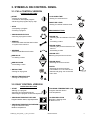
INDUSTRIAL TUMBLE DRYERS 20lb 25lb 30lb 40lb 50lb 75lb USER MANUAL 508982 M Publication date: 1 Oct 2010 USER'S MANUAL 1. TABLE OF CONTENTS 1. TABLE OF CONTENTS ................................................................................................ 1 2. WARNINGS AND LABELS ........................................................................................... 2 2.1. SYMBOLS ON THE MACHINE...............................................................................................................3 2.2. INSTRUCTIONS FOR DRYING..............................................................................................................3 2.3. WRONG USAGE OF THE MACHINE.....................................................................................................3 2.4. INSTRUCTIONS FOR MAINTENANCE, ADJUSTMENT AND SAFETY OF PEOPLE..........................4 3. SYMBOLS ON CONTROL PANEL ............................................................................... 5 3.1. FULL CONTROL VERSION....................................................................................................................5 3.2. EASY CONTROL VERSION ...................................................................................................................5 4. OPERATING INSTRUCTIONS...................................................................................... 6 4.1. START THE MACHINE...........................................................................................................................6 4.2. POWER SUPPLY....................................................................................................................................6 4.3. STARTING THE DRYING PROCESS ....................................................................................................6 4.4. FINISHING THE DRYING CYCLE..........................................................................................................7 4.5. EMERGENCY STOP OF THE MACHINE ..............................................................................................7 4.6. HOW TO PROCEED ON ERROR MESSAGES .....................................................................................8 4.7. POWER SUPPLY INTERRUPTION........................................................................................................8 4.8. INTERRUPTION OF GAS SUPPLY .......................................................................................................8 4.9. RESET OF GAS HEATING.....................................................................................................................8 5. EXPLANATION ERROR MESSAGES .......................................................................... 9 5.1. HUMIDITY CONTROL - TROUBLE SHOOTING..................................................................................20 508982_M_PUB_DATE_1_OCT_2010.DOC USER’S MANUAL 1 2. WARNINGS AND LABELS TO MINIMIZE THE RISK OF FIRE, INJURY BY ELECTRIC SHOCK OR SERIOUS INJURIES TO PEOPLE OR PROPERTY DAMAGE, PLEASE READ AND FOLLOW THE FOLLOWING INSTRUCTIONS. – This version is the original version. Without this version, the instructions are incomplete. – Before installation, operation and maintenance of the machine read carefully the complete instructions, i.e. this „Installation, maintenance and user's manual“, „Programming manual“ and „Spare parts manual“. The Programming manual and Spare parts manual are not delivered with a machine by default. You shall ask the supplier / manufacturer to obtain Programming manual and Spare parts manual. – Follow the instruction written in manuals and keep the manuals in a proper place by the machine for later use. – Do not bypass the instructions stated in the instruction manual, and warnings on the labels. Follow all basic and valid safety instructions. – Children can not operate this machine. Before turning the machine „ON“, make sure that there are no people or animals present in or around the machine. – Do not operate the machine with broken / missing parts, opened covers, also do not operate a machine that was not installed and put in operation according to instructions stated in the „Installation and maintenance manual“. – Do not tamper with the machine‘s control. – Machine version OPL (without coin meter) is intended for qualified operator. – Do not store flammable materials around the machine. Keep the machine surface clean and without flammable materials and remove dust from filter once a day. – DO NOT spray or store aerosols in the vicinity of this appliance. – Various chemicals used in laundries contain chlorine (some dry cleaning fluids, aerosols, bleaches). When decomposed in a flame, these materials may rapidly corrode and destroy this appliance. – When the main switch is „OFF“, the supply terminals are still under current. – DO NOT bypass any safety devices. – Do not remove warning signs placed on the appliance. Observe signs and labels to avoid personal injuries. – Always follow the fabric care instructions supplied by the garment manufacturer. – DO NOT reach into tumbler if tumbler is revolving. – Dryer must be exhausted outdoors and area around dryer must be free of lint because dryer produces combustible lint. – The dryer produces equivalent continuous (A-weighted) sound power level which doesn't exceed 70 dB (A). – Use the dryer only for its intended purpose, drying water-washed fabrics. – Only qualified service personnel may open the appliance to carry out servicing. – Follow all valid basic safety rules and laws. The instructions in this manual cannot account for every possible dangerous situation. They must be generally understood. Caution and care are factors which can not included in the design of the appliance and all persons who install, operate or maintain the appliance must be qualified and familiar with the operating instructions. It is up to the user to take proper care when operating the appliance. – The manufacturer reserves the right to change the manuals without previous notice. – If any problems or failures should arise, immediately contact your dealer, serviceman or manufacturer. To avoid creating any flammable vapours that may explode, ignite or cause corrosive damage, DO NOT dry the following materials: – Articles that have been cleaned in, soaked in, washed in or spotted with gasoline, dry cleaning solvents or other flammable/explosive substances. – Plastics or articles containing foam rubber or similarly textured rubber like materials. – Articles that have traces of flammable substances like cooking oil, machine oil, flammable chemicals or thinner. – Articles containing wax or cleaning chemicals. – Fiberglas curtains or draperies (unless the label says it can be done). FOR GAS HEATED VERSION – Turn off the main gas supply when discovering a gas leak from the machine. Ventilate the premises, do not turn on any electrical devices, do not smoke, do not use open flame and call the maintenance. – Do not eliminate nor change settings of the underpressure switch, safety thermostat, primary air suction and all factory preset devices. FOR STEAM HEATED VERSION – Turn off the main steam supply when discovering that steam is leaking from the machine, and call the maintenance. 2 USER'S MANUAL 508982_M_PUB_DATE_1_OCT_2010.DOC ! WARNING! IF THE INSTALLED APPLIANCE OPERATE WITH COIN, TOKEN OR SIMILAR OPERATION FOR USE IN SELFSERVICE SITUATIONS, THEN THE OWNER-INSTALLER MUST PROVIDE A REMOTE-LOCATED EMERGENCY STOP DEVICE. THIS DEVICE MUST BE PLACED IN SUCH A WAY THAT IT IS EASY AND SAFELY ACCESSIBLE FOR THE USERS. THE EMERGENCY STOP DEVICE TAKES CARE THAT AT LEAST THE CONTROL CIRCUIT OF THE APPLIANCE IS INTERRUPTED. ! WARNING! ORIGINAL OR IDENTICAL PARTS MUST BE USED FOR REPLACEMENT IN THIS MACHINE. AFTER SERVICING REPLACE AND SECURE ALL PANELS IN THE ORIGINAL WAY. TAKE THESE MEASURES FOR CONTINUED PROTECTION AGAINST ELECTRICAL SHOCK, INJURY, FIRE AND/OR PROPERTY DAMAGE. 2.1. SYMBOLS ON THE MACHINE Warning, dangerous electrical current, electric device. Disconnect the power supply to the machine before doing any interventions into the machine. When the main switch is „OFF“, the supply terminals are still under current. Warning, high temperature Filter label 531406 Do not touch the area after the machine has been heated up. Main switch Warning, read and keep written instructions 2.2. INSTRUCTIONS FOR DRYING The machine is intended only for drying the flat linen (bed-linen, table-cloths, dish-towels, towels, handkerchiefs and other kinds of flat linen) and garments made of flax, wool, cotton, silk, polyacryl and polyester fibre. Before drying make sure whether manufacturer labelled the linen as possible to dry in the dryer. The manufacturer is not responsible for any fabric damage caused by improper drying action. The machine is not intended for drying the linen containing parts of plastics, glass fibres and foam rubber. Before starting the drying action, remove any articles from garments, as e.g. nails, pins, screws, etc. which could damage the garments as well as the machine. Linen must be rinsed and spin-dried properly. Recommended residual moisture of linen before drying should be 50% - 70% to get an optimal result. For the machine correct function it is necessary to clean the lint filter once a day at least. Stop the machine before you clean the filter. Remove cover of lower panel. For double dryer 13/13kg open both filter covers. Remove the lint filter and clean it. At the same time clean area in front of the lint filter. Pieces of lint on this area would pollute the lint filter and reduce effectiveness of drying process. Put the filter back and close the cover. Always finish the drying cycle by cooling down the linen. Remove the linen immediately after finishing the drying cycle. 2.3. WRONG USAGE OF THE MACHINE ! WARNING ! THIS MACHINE IS DESIGNED FOR INDUSTRIAL DRYING OF LINEN. IT IS NOT INTENDED FOR HOUSEHOLD USE. ANY USAGE DIFFERENT THAN MENTIONED ABOVE, WITHOUT WRITTEN AGREEMENT OF THE SUPPLIER, WILL BE CONSIDERED AS IMPROPER USAGE. – Do not load the machine with bigger amount of linen than it is designed for. – Do not forget to clean the lint filter regularly. – Do not stop the machine until the drying cycle including cooling down is finished, except of emergency events. – Do not dry synthetic fabrics at high temperature. – Do not leave the linen in the machine after the drying cycle is finished. 508982_M_PUB_DATE_1_OCT_2010.DOC USER’S MANUAL 3 2.4. INSTRUCTIONS FOR MAINTENANCE, ADJUSTMENT AND SAFETY OF PEOPLE The following information are not mentioned in this „User's manual“. You can find missing information in „Installation and maintenance manual“, which is delivered with the machine. References to „Installation and maintenance manual“ according to norm EN ISO 10472-1(-4): 1. Information about providing the user's manual 2. Extent of the machine usage and limits 3. Maintenance and adjustment 4. Ventilation 5. Covers 6. Defects, cleaning, maintenance 7. Thermal risks 8. Exhaust system 9. Handling, installation 4 USER'S MANUAL 508982_M_PUB_DATE_1_OCT_2010.DOC 3. SYMBOLS ON CONTROL PANEL 3.1. FULL CONTROL VERSION OPERATION BUTTONS START - Starting up a program - Continue an interrupted program - Advancing the program step by step STOP - Interrupting a program - Finishing a program PROGRAM SELECTION - Selecting a program number SERVICE - shows the states and the total number of cycles of the machine REVERSE - Switch On/Off Reverse function. ARROW UP - Increasing a value ARROW DOWN - Decreasing a value DRYING TIME - Setting for drying time COOLDOWN TIME - Setting for cool down time MOISTURE LEVEL - Setting for residual moisture level PROGRAM BUTTONS ARROW UP - Selecting the next element of an item list - Increasing a value ARROW DOWN - Selecting the previous element of an item list - decreasing a value ARROW LEFT - Selecting the previous menu item ARROW RIGHT - Selecting the next menu item ENTER - Selecting the next menu item - Confirmation of a new value or list element and going over to the next menu item DRYING TEMPERATURE - Setting for temperature 3.2. EASY CONTROL VERSION OPERATION BUTTONS START - Starting up a program - Continue an interrupted program - Advancing the program to the next sequence PROGRAM TEMPERATURE LOW - Program selection button Low temperature PROGRAM TEMPERATURE HIGH - Program selection button, High temperature ALARM INDICATION - Red light is flashing when an alarm occurs PROGRAM TEMPERATURE MEDIUM - Program selection button, Medium temperature 508982_M_PUB_DATE_1_OCT_2010.DOC USER’S MANUAL 5 4. OPERATING INSTRUCTIONS 4.1. START THE MACHINE Before the first start-up, make sure whether the machine is installed properly - see „Installation and maintenance manual“. Check the lint filter and other parts of the machine according to „Installation and maintenance manual“. 4.2. POWER SUPPLY Turn the main switch on the machine rear cover to position „on“. If the machine is equipped with emergency button, turn it slightly on the right. Display will light up. After few seconds it will fade - valid for Easy control version. The machine remains in stand-by mode. 4.3. STARTING THE DRYING PROCESS 4.3.1. FULL CONTROL VERSION 1. Open tumbler door, load with laundry and securely close door. 2. Select desired Program setting. Do not select temperature that is higher than the laundry maximum temperature. (For details on pre-set drying temperatures and times revert to „Programming manual Full Control“). The program number will light on the display. For manual set-up of drying, press repeatedly the button Program until you overstep program 20. Press the button Drying time, Drying temperature, Cool down time, Moisture degree for setting-up of individual parameters. Set required value using the button arrow up or arrow down. Press enter to confirm the value. 3. Press Start. 4. Select Reversing or Non-Reversing. This selection is optional. Not applicable for Non-Reversing model. 5. To load or unload tumbler during drying cycle, follow these steps: a. Stop tumbler by opening tumbler door. b. Load or unload tumbler. c. Restarting dryer: 1. Close tumbler door. 2. Press Start. 6. Cycle is finished as soon as the sign „!UNLOAD!“ is displayed. 7. Remove load immediately after cycle is finished. NOTE: TO INTERUPT PROGRAM, PRESS STOP ONCE. TO CANCEL PROGRAM, PRESS STOP TWICE. Stop button : 4.3.2. EASY CONTROL VERSION 1. Open the door and load the laundry into the drum. When the drum is loaded, close the door. 2. Select drying program : Version - Easy Control without coin meter : Select the program by pressing the temperature button. Do not select temperature that is higher than the laundry maximum temperature. (For details on pre-set drying temperatures and times revert to „Programming manual Easy Control“). The program number will light on the display. Version - Easy Control with coin meter : Select the program by pressing the temperature button. Do not select temperature that is higher than the laundry maximum temperature. Insert a coin. The pre-paid time value will be displayed. Insert further coins until the required drying time is reached. 3. Start the drying program : 6 USER'S MANUAL 508982_M_PUB_DATE_1_OCT_2010.DOC The START button LED is flashing. Press the START button. 4. Changing the drying programs : It is possible to change the drying programs while the machine is working. Version - Easy Control without coin meter : Select another program by pressing the relevant temperature button. The program will increase or decrease the drying temperature. The drying time remains unchanged. Version - Easy Control with coin meter : Select another program by pressing the relevant temperature button. The program will increase or decrease the drying temperature. The program will recalculate the remaining amount of money. The drying time will be adapted accordingly. 5. Increasing the drying temperature : Version - Easy Control without coin meter : Press the active temperature button. The dot on the display will stop flashing. Press the button again to increase the drying time. Version - Easy Control with coin meter : Increasing of the drying temperature is not possible. 6. Advancing the drying program : Version - Easy Control without coin meter : Press the button START while the machine is working. The program will be advanced to further step. Version - Easy Control with coin meter : Advancing the program is not possible. 7. Program end : The time on the display will count down until „0“. When „0“ is reached. The drying cycle is finished and the door can be opened. Remove the load immediately after the drying process is finished to avoid risk of linen burning. REMARKS : 1. Loading and unloading the machine during drying process : Stop the dryer by opening the door. Load or unload the linen in or from the dryer. Be careful since the linen load can be significantly hot. Close the door. Press the START button. 2. Interrupting of the drying process : Version - Easy Control without coin meter : Advance the drying program into next step by pressing the START button. Repeat the sequence until the end of the program is reached. Version - Easy Control with coin meter : Interruption of drying program is not possible in operation mode. IMPORTANT: ALL MANUALLY OPERATED DRYERS ARE FACTORY EQUIPPED WITH AN EMERGENCY STOP BUTTON LOCATED ON THE FRONT PANEL (NOT VALID FOR VERSION WITH COIN METER). Emergency stop button: 4.4. FINISHING THE DRYING CYCLE After the drying cycle is finished, the machine is prepared for another cycle. If you want to switch the machine off, press emergency stop button (not valid for Easy Control with coin meter). To switch off the machine completely, turn the main switch on the machine rear panel to position „OFF“. ! WARNING ! DO NOT INTERRUPT DRYING PROGRAM AND DO NOT SKIP THE STEP „COOL DOWN“ AT THE END OF DRYING CYCLE. 4.5. EMERGENCY STOP OF THE MACHINE Versions - Full Control and Easy Control without coin meter : If operator‘s safety or health is endangered, it is possible to stop the machine by pressing the button of emergency stop, see chapter 4.3. Emergency stop button is located on the machine upper front panel. Version - Easy Control with coin meter : The machine is not equipped with central stop button. The laundry owner must be make arrangements for remote-located emergency stop device. 508982_M_PUB_DATE_1_OCT_2010.DOC USER’S MANUAL 7 ! WARNING ! AS SOON AS THE REASON FOR THE MACHINE STOPPAGE IS ELIMINATED, UNLOAD THE LINEN FROM THE DRUM IMMEDIATELY. RISK OF FIRE! 4.6. HOW TO PROCEED ON ERROR MESSAGES Version - Full Control : Error message occurs on the machine display in the form of Er: and no. of failure (001 - 999). In some cases the programmer buzzer sounds. In some cases the drum goes on turning but the heating is off. The machine cools down and stops itself after it has reached safety temperature. After the machine has been stopped, the error message is possible to delete by opening and closing the door, possibly by pressing the button of emergency stop. If failure state continues, the error message is displayed again. For detailed information concerning error messages - see „Programming manual“. Version - Easy Control without coin meter and with coin meter : When there is an error the fault LED lights on. The number on the display corresponds with specific fault. In some cases the drum goes on turning but the heating is off. The machine cools down and stops itself after it has reached safety temperature. For detailed information concerning error messages - see „Programming manual“. 4.7. POWER SUPPLY INTERRUPTION Version - Full Control : When the power supply interruption occurs and the power is restored the machine will be in stand-by mode. The display is counting down. Once the display reaches 0 the machine will be waiting for further instruction. Close the door in case it is open. On the display the program number will be shown. Press the Start button to continue on the program, or press the STOP button to end the drying cycle. Version - Easy Control without coin meter and with coin meter : When the power supply interruption occurs and the power is restored the machine will be in stand-by mode. The display is counting down. Once the display reaches 0 the machine will be waiting for further instruction. Close the door in case it is open. On the display the program number will be shown and the LED on START button is flashing. Press the Start button to continue on the program. ! WARNING ! UNLOAD THE LINEN FROM DRYING DRUM. RISK OF FIRE AT HIGH TEMPERATURE OF DRYING! 4.8. INTERRUPTION OF GAS SUPPLY Version - Full Control : When gas supply is interrupted there is displayed the message „HEATING FAILURE“ or „NO HEAT“ when the temperature is not reached. The drum goes on turning but with heating off. As soon as it reaches the safety temperature it will stop. Error message is possible to delete - see chapter 4.6. When gas supply is recovered, it is possible to start the machine again. Version - Easy Control without coin meter and with coin meter : When gas supply is interrupted the display will show the gas error messages number 22, 23 or 24. The drum goes on turning but with heating off. As soon as the machine reaches safety temperature it will stop. For details on error messages revert to „Programming manual“. ! WARNING ! UNLOAD THE LINEN FROM DRYING DRUM. RISK OF FIRE AT HIGH TEMPERATURE OF DRYING! 4.9. RESET OF GAS HEATING After you start the machine, an electronic system of the machine will try three times the gas ignition. If the gas ignition does not occur during this time, the control unit of ignition will come over to safety block and the valve will not open until it is reset. There is a message on the display : Version - Full Control : „GAS IGNITION RESET/STOP“. Check the gas supply. Check whether the manual shut off valve of gas is open. When you press the button „START“, an electronic system of ignition will reset and the machine will repeat ignition sequence. Probably, it will be necessary to try several times to push out an air from the gas pipeline. If an error message is still displayed, put the machine out of operation and contact the manufacturer or your dealer. When you press the button „STOP“, the machine will stop. On the display there occurs an error message „ignition failure“. The error message is possible to delete - see chapter 4.6. Version - Easy Control without coin meter and with coin meter : „22“. Check the gas supply. Check whether the manual shut off valve of gas is open. Turn off and on the machine by emergency stop button - (valid for Easy control without coin meter) or by main switch. The machine ignition unit will reset. Probably, it will be necessary to try several times to push out an air from the gas pipeline. If the error message is still displayed put the machine out of operation and contact the manufacturer or your dealer. 8 USER'S MANUAL 508982_M_PUB_DATE_1_OCT_2010.DOC 5. EXPLANATION ERROR MESSAGES For each failure message diagnostics are added. IMPORTANT! TECHNICAL INTERVENTION ON THE DRYER IS ONLY FOR QUALIFIED TECHNICIANS WITH SUFFICIENT TECHNICAL KNOWLEDGE OF THE EASY CONTROL DRYER MACHINE. FAILURE 1 : HEATING SAFETY 1 Failure 1 occurs when the electronic timer detects that the heating safety located at the air outlet has opened it’s NC contact. (NC thermal contact) (failure 1 can only occur when the drying cycle is running). A skilled and experienced technician must examine the heating-and air outlet system before the machine is put in operation again. DIAGNOSE: 1. Check the air outlet system. 2. Check the temperature sensor. 3. Check the heating system. 4. Check the heating contactor (valve) 5. Check the wiring. 6. If the heating safety is not closing within 15 minutes. 7. Check the output relay that controls the heating system. 8. Check the input Signal by monitoring the state at the Service menu. If the air flow is not sufficient, adjust the air outlet system. If the temperature sensor is not measuring correctly, replace the temperature sensor. If the heating system is broken repair, replace the heating system. If the heating contactor (valve) is not functional repair or replace the component. If the wiring is damaged, repair the wiring. The heating safety will be probably broken and must be replaced. If the output relay is not functional, replace the electronic card. If the input is not functional anymore, replace the electronic card. FAILURE 2: HEATING SAFETY 2 Failure 2 occurs when the electronic timer detects that the heating safety located at the heater has opened it’s NC contact. (NC thermal contact) (failure 2 can only occur when the drying cycle is running). A skilled and experienced technician must examine the heating-and air outlet system before the machine is put in operation again. DIAGNOSE: 1. Check the air outlet system. 2. Check the temperature sensor. 3. Check the heating system. 4. Check the heating contactor (valve) 5. Check the wiring. 6. If the heating safety is not closing within 15 minutes. 7. Check the output relay that controls the heating system. 8. Check the input Signal by monitoring the state at the Service menu. If the air flow is not sufficient, adjust the air outlet system. If the temperature sensor is not measuring correctly, replace the temperature sensor. If the heating system is broken repair, replace the heating system. If the heating contactor (valve) is not functional repair or replace the component. If the wiring is damaged, repair the wiring. The heating safety will be probably broken and must be replaced. If the output relay is not functional, replace the electronic card. If the input is not functional anymore, replace the electronic card. FAILURE 5 : MOTOR THERMIC Failure 5 occurs when the motor temperature (overcurrent) security has tripped. The contact will be closed again automatically after some time. (Failure 5 occurs for 1 motor machines). (NC thermal contact) A skilled and experienced technician must examine the motor-drive system before the machine is put in operation again. 508982_M_PUB_DATE_1_OCT_2010.DOC USER’S MANUAL 9 DIAGNOSE: 1. Check if the thermal security of the motor is open. 2. Check that the air flow, drum and ventilator rotation is not obstructed. 3. If the thermal motor security is not closing after 15 minutes. 4. Check the continuity of the wiring. 5. Check the input signal by monitoring the state at the Service menu. If the thermal security is open, within 15 minutes the security will close automatically. If a motor is defective, the security can go open again when you restart the dryer. If it was only a temperature problem and the motor is not defective: the overload security will not trip again. Solve the mechanical problem. The thermal motor security will be probably broken. If the wiring is not continuous: repair the wiring. If the input is not functional anymore, replace the electronic card. FAILURE 6 : FAN MOTOR THERMIC Failure 6 occurs when the fan motor temperature (overcurrent) security has tripped. The contact will be closed again automatically after some time. (Failure 6 occurs only for 2 motor machines). (NC thermal contact). A skilled and experienced technician must examine the motor-drive system before the machine is put in operation again. DIAGNOSE: 1. Check if the thermal security of the motor is open. 2. Check that the air flow, drum and ventilator rotation is not obstructed. 3. If the thermal motor security is not closing after 15 minutes. 4. Check the continuity of the wiring. 5. Check the input signal by monitoring the state at the Service menu. If the thermal security is open, within 15 minutes the security will close automatically. If a motor is defective, the security can go open again when you restart the dryer. If it was only a temperature problem and the motor is not defective: the overload security will not trip again. Solve the mechanical problem. The thermal motor security will be probably broken. If the wiring is not continuous, repair the wiring. If the input is not functional anymore, replace the electronic card. FAILURE 7: DRUM MOTOR THERMIC Failure 7 occurs when the motor temperature (overcurrent) security has tripped. The contact will be closed again automatically after some time. (Failure 7 occurs only for 2 motor machines) (NC thermal contact). A skilled and experienced technician must examine the motor-drive system before the machine is put in operation again. DIAGNOSE: 1. Check if the thermal security of the motor is open. 2. Check that the air flow, drum and ventilator rotation is not obstructed. 3. If the thermal motor security is not closing after 15 minutes. 4. Check the continuity of the wiring. 5. Check the input signal by monitoring the state at the Service menu. 10 USER'S MANUAL If the thermal security is open, within 15 minutes the security will close automatically. If a motor is defective, the security can go open again when you restart the dryer. If it was only a temperature problem and the motor is not defective: the overload security will not trip again. Solve the mechanical problem. The thermal motor security will be probably broken. If the wiring is not continuous, repair the wiring. If the input is not functional anymore, replace the electronic card. 508982_M_PUB_DATE_1_OCT_2010.DOC FAILURE 8: AIR FLOW SWITCH OPEN AT STARTUP Failure 8 occurs when there is not sufficient air flow when the ventilator is switched On. This security function prevents that the heating is switched On when the ventilator is not functional or if the airflow is obstructed. (Failure 8 occurs only at startup) (NO contact) The Air Flow Switch has a safety function and it’s function must not be obstructed. A skilled and experienced technician must examine the dryer system before the machine is put in operation again. ! ATTENTION !!! FOR NEW INSTALLATIONS THE AIR OUTLET TUBES MUST HAVE THE RIGHT SIZE FOR THE AIR FLOW OF THE CORRESPONDING MACHINE. FOLLOW THE INSTRUCTIONS IN THE INSTALLATION MANUAL. DIAGNOSE: 1. Check if the ventilator is functional. 2. Check if there is sufficient air flow. Check if the Dryer is a closed box. (Lint filter Door, mechanical panels must be present and closed properly) 3. Check if the switch and metal plate and air flow detection system is still functional. 4. Check the continuity of the wiring 5. Check the input signal by monitoring the state at the Service menu. If the ventilator is not functional, repair or replace the ventilator, belt, motor control system, wiring or the power supply circuit of the ventilator. In normal operation, the Ventilator is switched On immediately after pressing the START button. The ventilator must stay on for the complete time of the drying cycle. When the Dryer is not a closed box, air will escape and the air flow will not be sufficient to switch the Air Flow Switch. Make sure that there is no loss of Air Flow. Example : close the Lint Filter Door properly. If the air flow detection system or it's switch is out of order, it must be repaired or replaced. If the wiring is not continuous : repair the wiring If the input is not functional anymore, replace the electronic card. FAILURE 9: AIR FLOW SWITCH OPEN AFTER STARTUP Failure 9 occurs when there is not sufficient air flow when the ventilator is turning. This security function makes that the heating is switched Off when the ventilator is suddenly Not functional anymore or if the airflow gets obstructed. (Failure 9 occurs only after startup) (NO contact) The Air Flow Switch has a safety function and it’s function must not be obstructed. A skilled and experienced technician must examine the dryer system before the machine is put in operation again. DIAGNOSE: 1. Check if the ventilator is functional. 2. Check if there is sufficient air flow. Check if the Dryer is a closed box. (Lint filter Door, mechanical panels must be present and closed properly) 3. Check if the switch and metal plate and air flow detection system is still functional. 4. Check the continuity of the wiring 5. Check the input signal by monitoring the state at the Service menu. 508982_M_PUB_DATE_1_OCT_2010.DOC If the ventilator is not functional, repair or replace the ventilator, belt, motor control system, wiring or the power supply circuit of the ventilator. In normal operation, the Ventilator is switched On immediately after pressing the START button. The ventilator must stay on for the complete time of the drying cycle. When the Dryer is not a closed box, air will escape and the air flow will not be sufficient to switch the Air Flow Switch. Make sure that there is no loss of Air Flow. Example : close the Lint Filter Door properly. If the air flow detection system or it's switch is out of order, it must be repaired or replaced. If the wiring is not continuous, repair the wiring If the input is not functional anymore, replace the electronic card. USER’S MANUAL 11 FAILURE 10: AIR FLOW SWITCH CLOSED Failure 10 occurs at the start of the drying cycle. Before the ventilator is switched On, the Air flow switch must be open. If the flow detection system is out of order and the switch is closed, an error message will be displayed. (Failure 10 occurs only in standby mode) (NO contact) The Air Flow Switch has a safety function and it’s function must not be obstructed. A skilled and experienced technician must examine the dryer system before the machine is put in operation again. DIAGNOSE: 1. Check if the air flow detection system is still functional. 2. Check if the ventilator is switched On immediately after pressing start. 3. Check the continuity of the wiring 4. Check that the ventilator is switched Off at the end of the drying cycle. 5. Check the input signal by monitoring the state at the Service menu. If the air flow detection system or it's switch is out of order, it must be repaired or replaced. Check the contactor, wiring and the ventilator command signal. If the wiring is not continuous, repair the wiring If the contactor is not correctly functioning, replace the contactor. If the input is not functional anymore, replace the electronic card. FAILURE 11: FAULT COOLDOWN Failure 11 occurs when the temperature doesn’t decrease when the Cooldown sequence is in progress. (No cooldown at all after 15 minutes at cooldown sequence for temperature above 50°C.) A skilled and experienced technician must examine the heating-and air outlet system before the machine is put in operation again. DIAGNOSE: 1. Check if the heating system is switched Off. 2. Check if the temperature sensor is functional. 3. Check the output relay that controls the heating system. If no temperature ramp has been programmed for the cooldown sequence, the heating system must be switched Off. Check the contactor (valve), wiring, and the ventilator command signal. If the temperature sensor is not measuring correctly, replace the temperature sensor. If the output relay is not functional, replace the electronic card. FAILURE 12: NO REHEATING Failure 12 occurs at a heating (cooldown with ramp) sequence when the heating is not switched On again at the temperature control process when the lowest temperature hysteresis value is reached. A skilled and experienced technician must examine the heating-and air outlet system before the machine is put in operation again. DIAGNOSE: 1. Check if there is no interruption of the electrical power, gas or steam heating power supply 2. Check if the heating system is functional. 3. Check the heating contactor (valve) 4. Check the continuity of the wiring. 5. Check if the temperature sensor is functional. 6. Check the output relay that controls the heating system. 12 The machine will not heat when there is no energy supply for the heating system. Avoid interruptions of the energy supply. If the heating system fails to work, repair or replace the heating system. If the heating contactor (valve) is not functional repair or replace the component. If the wiring is not continuous : repair the wiring If the temperature sensor is not measuring correctly, replace the temperature sensor. If the output relay is not functional, replace the electronic card. USER'S MANUAL 508982_M_PUB_DATE_1_OCT_2010.DOC FAILURE 13: NO HEATING Failure 13 occurs when the heating system is not functional at start up. (No temperature raise of 5°C in 30 minutes after start drying cycle.) A skilled and experienced technician must examine the heating-and air outlet system before the machine is put in operation again. DIAGNOSE: 1. Check if there is no interruption of the electrical power, gas or steam heating power supply 2. Check if the heating system is functional. 3. Check the heating contactor (valve) 4. Check the continuity of the wiring. 5. Check if the temperature sensor is functional. 6. Check the output relay that controls the heating system. The machine will not heat when there is no energy supply for the heating system. Avoid interruptions of the energy supply. If the heating system fails to work, repair or replace the heating system. If the heating contactor (valve) is not functional repair or replace the component. If the wiring is not continuous, repair the wiring If the temperature sensor is not measuring correctly, replace the temperature sensor. If the output relay is not functional, replace the electronic card. FAILURE 15: TOO HOT Failure 15 occurs when the actual heating temperature goes 15°C above the target temperature at the drying process. A skilled and experienced technician must examine the heating-and air outlet system before the machine is put in operation again. DIAGNOSE: 1. Check the air outlet system. 2. Check the temperature sensor. 3. Check the heating system. 4. Check the heating contactor (valve) 5. Check the wiring. 6. Check the output relay that controls the heating system. 7. Check the input Signal by monitoring the state at the Service menu. If the air flow is not sufficient, adjust the air outlet system. If the temperature sensor is not measuring correctly, replace the temperature sensor. If the heating system is broken, repair or replace the heating system. If the heating contactor (valve) is not functional repair or replace the component. If the wiring is damaged, repair the wiring. If the output relay is not functional, replace the electronic card. If the input is not functional anymore, replace the electronic card. FAILURE 16: COIN BLOCKING 1 Failure 16 occurs when the input for coin drop 1 is blocked for more then 5 seconds. Case EP = ON. Fault 16 will be displayed if the external start release signal is high for more then 10 seconds when the door has been opened at the end of the program. DIAGNOSE: 1. Check the well functioning of coin drop 1 2. Check the continuity of the wiring If the coin drop micro contact or optocoupler is not functioning 100%, replace the coin drop If the wiring is not continue : repair the wiring FAILURE 17: COIN BLOCKING 2 Failure 17 occurs when the input for coin drop 2 is blocked for more then 5 seconds. DIAGNOSE: 1. Check the well functioning of coin drop 2 2. Check the continuity of the wiring 508982_M_PUB_DATE_1_OCT_2010.DOC If the coin drop micro contact or optocoupler is not functioning 100%, replace the coin drop If the wiring is not continue: repair the wiring USER’S MANUAL 13 FAILURE 18: TOO HOT SAFETY Failure 18 occurs when the actual heating temperature rises above safety temperature 85°C while the machine is waiting to be started (not running). On the display will be shown „Hot“ and the air temperature as indication that there is something wrong. Check Safety Thermostats ST1 & ST2 as they should switch off the heating system and prevent high temperatures. A skilled and experienced technician must examine the heating-and air outlet system before the machine is put in operation again. ! ATTENTION !!! IF FAILURE 18 OCCURS WE CAN EXPECT THERE IS RISK OF BURN AND NECESSARY ACTIONS MUST BE TAKEN TO REDUCE TEMPERATURE. DIAGNOSE: 1. Check the air outlet system. 2. Check the temperature sensor. 3. Check the heating system. 4. Check the heating contactor (valve) 5. Check the wiring. 6. Check the Safety Thermostats ST1 & ST2. 7. Check the output relay that controls the heating system. 8. Check the input Signal by monitoring the state at the Service menu. If the air flow is not sufficient, adjust the air outlet system. If the temperature sensor is not measuring correctly, replace the temperature sensor. If the heating system is broken, repair or replace the heating system. If the heating contactor (valve) is not functional repair or replace the component. If the wiring is damaged, repair the wiring. The Safety Thermostats should go open before failure 18 is generated. If the output relay is not functional, replace the electronic card. If the input is not functional anymore, replace the electronic card. FAILURE 19: DEFECTIVE TEMPERATURE SENSOR 1 Failure 19 occurs when the temperature sensor is broken. The fault is only displayed when the machine is in standby mode and no program is active. The fault can only be erased by switching off and on the power. If the fault is still present after switching on the power : fault message 19 will be generated again. A skilled and experienced technician must examine the heating-and air outlet system before the machine is put in operation again. DIAGNOSE: 1. Check if the temperature sensor is connected on the PCB Board. 2. Check the temperature sensor 3. Measure the resistance of the sensor 4. Check if the earth wire is at the middle position of the connector 5. If the fault is persistent The Female connector must be connected with the Male connector T1 of the PCB board. If the temperature sensor is broken: replace the temperature sensor If the resistance is not OK, replace the temperature sensor If the earth wire is not at the middle position: put the earth wire in the middle position of connector T Replace the electronic board Be sure that the problem is related to the electronic board and not to a defective temperature sensor FAILURE 20: DEFECTIVE TEMPERATURE SENSOR 2 Failure 20 occurs when the temperature sensor is broken. The fault is only displayed when the machine is in standby mode and no program is active. The fault can only be erased by switching off and on the power. If the fault is still present after switching on the power : fault message 20 will be generated again. A skilled and experienced technician must examine the heating-and air outlet system before the machine is put in operation again. 14 USER'S MANUAL 508982_M_PUB_DATE_1_OCT_2010.DOC DIAGNOSE: 1. Check if the temperature sensor is connected on the PCB Board. 2. Check the temperature sensor 3. Measure the resistance of the sensor 4. Check if the earth wire is at the middle position of the connector 5. If the fault is persistent The Female connector must be connected with the Male connector T2 of the PCB board. If the temperature sensor is broken: replace the temperature sensor If the resistance is not OK, replace the temperature sensor If the earth wire is not at the middle position: put the earth wire in the middle position of connector T Replace the electronic board Be sure that the problem is related to the electronic board and not to a defective temperature sensor FAILURE 22: IGNITION ERROR AT STARTUP, GAS HEATING ONLY Failure 22 occurs when the heating system has a problem to switch on the fire at start up. If the problem is still persistent after 3 automatic resets, error message 22 is generated. The dryer computer will try up to 9 times to turn on the gas heating. The gas ignition system closes contactor KA3 (input 4 High) to inform the dryer computer that the gas ignition system failed to switch on the fire. Then the ignition system is reset by the dryer computer by switching on the reset signal gas ignition system (contactor KA2)) A skilled and experienced technician must examine the heating- and air outlet system before the machine is put in operation again. DIAGNOSE: 1. Check the gas supply. 2. Check the heating system. 3. Check the gas ignition system. 4. Check the heating contactor. 5. Check contactor KA3 (Ignition Error). 6. Check the wiring. 7. Check the output relays that controls the heating system. 8. Check the electrical Input Ignition Error at the electronic card. Without gas supply, the heater can’t function. Right Gas supply and pressure must be available. If the heating system is broken repair, replace the heating system. If the gas ignition system is not functional, replace the gas ignition system. If a heating contactor is not functional replace the component. If the contactor KA3 is not functional replace the component. If the wiring is damaged, repair the wiring. If an output relay is not functional, replace the electronic card. If the input of the electronic card is not functional anymore, replace the electronic card. FAILURE 23: IGNITION ERROR AFTER STARTUP (RUN), GAS HEATING ONLY Failure 23 occurs when the heating system has a problem to switch on the fire when the dryer tries to restart the gas heating system. (while the dry cycle is running). If the problem is still persistent after 3 automatic resets, error message 23 is generated. The dryer computer will try up to 9 times to turn on the gas heating. The gas ignition system closes contactor KA3 (input 4 High) to inform the dryer computer that the gas ignition system failed to switch on the fire. Then the ignition system is reset by the dryer computer by switching on the reset signal gas ignition system (contactor KA2)) A skilled and experienced technician must examine the heating- and air outlet system before the machine is put in operation again. DIAGNOSE: 1. Check the gas supply. 2. Check the heating system. 3. Check the gas ignition system. 508982_M_PUB_DATE_1_OCT_2010.DOC Without gas supply, the heater can’t function. Right Gas supply and pressure must be available. If the heating system is broken repair, replace the heating system. If the gas ignition system is not functional, replace the gas ignition system. USER’S MANUAL 15 4. Check the heating contactor. 5. Check contactor KA3 (Ignition Error). 6. Check the wiring. 7. Check the output relays that controls the heating system. 8. Check the electrical Input Ignition Error at the electronic card. If a heating contactor is not functional replace the component. If the contactor KA3 is not functional replace the component. If the wiring is damaged, repair the wiring. If an output relay is not functional, replace the electronic card. If the input of the electronic card is not functional anymore, replace the electronic card. FAILURE 24: IGNITION ERROR FAILURE, GAS HEATING ONLY Failure 24 occurs after 3 attempts when the Gas Ignition system fails to be reset. Cause : Input Signal Ignition Error Failure stays high (Input 4) nevertheless 3 attempts of dryer computer to reset gas ignition system (contactor KA2). This is to be considered a major hardware failure. A skilled and experienced technician must examine the heating- and air outlet system before the machine is put in operation again. DIAGNOSE: 1. Check the gas ignition system. 2. Check the wiring. 3. Check contactor KA3 (Ignition Error). 4. Check the electrical Input Ignition Error at the electronic card. If the gas ignition system is broken, replace the gas ignition system. If the wiring is damaged, repair the wiring. If the contactor KA3 is not functional replace the component. If the input of the electronic card is not functional anymore, replace the electronic card. FAILURE 25: NO HUMIDITY SENSOR HUMIDITY CONTROL ONLY Failure 25 occurs when the humidity sensor doesn't give an analog electrical output signal to the dryer computer. Example: connector not connected to dryer computer. (At the „t“-menu you can switch off/on the Humidity Control function) (Note : the humidity sensor needs 1 minute after switching on the power supply dryer to stabilise it’s analog output signal) Failure 25 can occur when the dryer is running without linen inside. This should not be considered as a system failure. Check correct dryer operation with a normal amount of wet linen. ! ATTENTION THE HUMIDITY CONTROL SYSTEM IS NOT MADE TO RUN WITHOUT LOAD OR WITH A VERY SMALL LOAD. THE SYSTEM CAN ONLY FUNCTION IN A NORMAL WAY WHEN THERE IS SUFFICIANT EVAPORATION TO BE MEASURED BY THE AIR HUMIDITY SENSOR DIAGNOSE: 1. Check if the humidity sensor is connected to the dryer computer. 2. Check the wiring. 3. Check the supply voltage humidity sensor. 4. Check the humidity sensor and amplifier. 5. Check the analog input signal. (Inputs can be checked one by one in the Service menu) If the humidity sensor is not connected to the dryer computer, connect the sensor If the wiring is damaged, repair the wiring. If there is no or wrong supply voltage replace the dryer computer. If the humidity sensor or amplifier is damaged replace the humidity sensor and amplifier. If for A3, the value at the Analog input menu = „0“ then the analog input signal is missing. If the input of the controller board is not functional, replace the controller board. (check first previous items) FAILURE 26: NO HUMIDITY SENSOR CAP HUMIDITY CONTROL ONLY Failure 26 occurs when the dust cap at the humidity sensor is missing. When the dust cap is missing, due to the influence of the air flow in the dryer, the sensor will measure a too big value which is out of range at normal operation. (At the „t“-menu you can switch off/on the Humidity Control function) 16 USER'S MANUAL 508982_M_PUB_DATE_1_OCT_2010.DOC (Note : the humidity sensor needs 1 minute after switching on the power supply dryer to stabilise it’s analog output signal) DIAGNOSE: 1. Check if the dust cap is mounted on the sensor. 2. Check the wiring. 3. Check the supply voltage humidity sensor. If the dust cap is missing or broken, put a new dust cap on the humidity sensor. If the wiring is damaged, repair the wiring. If there is no or wrong supply voltage replace the dryer computer. If the humidity sensor or amplifier is damaged replace the humidity sensor and amplifier. If for A3, the value at the Analog input menu > „800“ then the analog input signal is out of range. If the input of the controller board is not functional, replace the controller board. (check first previous items) 4. Check the humidity sensor and amplifier. 5. Check the analog input signal. (Inputs can be checked one by one in the Service menu) ! ATTENTION !!! IF THE DRYER IS EXECUTED WITH AIR HUMIDITY SENSOR, THE DRYER CAN ONLY OPERATE CORRECTLY IF THE DUST CAP IS MOUNTED ON THE AIR HUMIDITY SENSOR. FAILURE 27: NO HUMIDITY REDUCTION HUMIDITY CONTROL ONLY Failure 27 occurs when the humidity value doesn’t decrease within 60 minutes when the drying sequence is in progress. (Maximum drying time by humidity control is set default on 60 minutes.) DIAGNOSE: 1. Check if the humidity sensor is functional. 2. Check if the humidity sensor is functional. 3. Check if the humidity sensor is functional. 4. Check if the heating-drying system is functional. 5. Check if the analog input and power supply of the sensor on the electronic card is functional. Check if there is no lint that obstructs the well functioning of the sensor. If the wiring of the sensor is broken repair the wiring. If the sensor is not functional at all, replace the sensor. (If you blow with your mouth on the sensor, the humidity value must change.) (remove filter cap first) If there is not sufficient airflow or heating power, the fabrics in the dryer will not get dry. Repair the problem. If the sensor control circuit is not functional, replace the electronic card. FAILURE 28: LINT FILTER Failure 28 occurs when the Lint Filter Door has not been opened for 40 succeeding cycles. Check The value of the Lint Filter Door Cycle Counter can be inspected at the Running State-Service menu. (Special function button) DIAGNOSE: 1. The Lint Filter must be cleaned every day. 2. Check if the Lint Filter Door Cycle Counter is reset by opening the Lint Door. 3. Check if the Lint Filter Door Cycle Counter is reset by opening the Lint Door. 4. Check if the Lint Filter Door Cycle Counter is reset by opening the Lint Door. If the Lint Filter has not been cleaned for 40 days, open the Lint Door and clean the Filter. Close the door again. The Lint Filter Door Cycle will be reset. If the Lint Filter Door Switch is broken, replace the Lint Filter Door Switch (Normal Closed Contact) If the wiring is broken, repair the wiring. If the input of the electronic card is not correctly functioning, replace the electronic card. FAILURE 30: BROKEN RELAIS EXTERNAL PAYMENT SYSTEM Failure 30 occurs when the External payment system relais stays closed for longer then the maximum allowed drying time (60 minutes). 508982_M_PUB_DATE_1_OCT_2010.DOC USER’S MANUAL 17 Only applicable for set-up selection "EP = RL3". The dryer will run as long as the external payment system relais is closed. As the dryer should not run longer then maximum allowed drying time, it will be stopped for safety purposes. DIAGNOSE: 1. Check it the right machine set-up has been selected. 2. Check the external payment system. 3. Check the wiring. 4. Check the electrical Input at the electronic card. Select the right setup. If the external payment system is broken, repair the system. If the wiring is damaged, repair the wiring. If the input of the electronic card is not functional anymore, replace the electronic card. FAILURE 35: WRONG SOFTWARE VERSION When a total new software that isn’t downward compatible with previous software versions is loaded, then the software will detect that the old and new softwares are not compatible. You have to reconfigure the Full Control Dryer Computer. ! ATTENTION !!! ALL THE CUSTOM SETTINGS WILL BE ERASED IN THE FULL CONTROL DRYER COMPUTER BY LOADING THE FACTORY SETTINGS. After reinitialization of the Full Control Dryer Computer, fault 35 can only be erased by switching the power Off/On. FAILURE 36: TOO HOT END Failure 36 occurs when the actual cooldown temperature at the end of the dry cycle is still above 78°C. If at the end of the drying cycle the temperature is above 78°C the dryer will go on with the cooldown sequence for 60 minutes (or until temperature below 65°C or until open door) . If the temperature is still above 70°C after these 60 extra minutes cooldown Failure 36 is generated. On the display will be shown „Hot“ and the air temperature as indication that there is something wrong. DIAGNOSE: 1. Check the air outlet system. 2. Check the temperature sensor. 3. Check the heating system. 4. Check the heating contactor (valve) 5. Check the wiring. 6. Check the output relay that controls the heating system. 7. Check the Analog Temperature input Signal by monitoring the state at the Service menu. If the air flow is not sufficient, adjust the air outlet system. If the temperature sensor is not measuring correctly, replace the temperature sensor. If the heating system is broken, repair or replace the heating system. If the heating contactor (valve) is not functional repair or replace the component. If the wiring is damaged, repair the wiring. If the output relay is not functional, replace the electronic card. If the input is not functional anymore, replace the electronic card. FAILURE 37: TOO HOT SAFETY Failure 37 occurs when the actual heating temperature rises above safety temperature 85°C while the machine is running. ( (*) T24 & T35 ELECTRICAL HEATING ONLY: 100°C) If at the end of the drying cycle the temperature is above 85°C ( (*) 100°C) the dryer will go on with the cooldown sequence for 30 minutes (or until temperature below 65°C or until open door). On the display will be shown „Hot“ as indication that there is something wrong. Check Safety Thermostats ST1 & ST2 as they should switch off the heating system and prevent high temperatures. A skilled and experienced technician must examine the heating-and air outlet system before the machine is put in operation again. ! ATTENTION !!! IF FAILURE 37 OCCURS WE CAN EXPECT THERE IS RISK OF BURN AND NECESSARY ACTIONS MUST BE TAKEN TO REDUCE TEMPERATURE. 18 USER'S MANUAL 508982_M_PUB_DATE_1_OCT_2010.DOC DIAGNOSE: 1. Check the air outlet system. 2. Check the temperature sensor. 3. Check the heating system. 4. Check the heating contactor (valve) 5. Check the wiring. 6. Check the Safety Thermostats ST1 & ST2. 7. Check the output relay that controls the heating system. 8. Check the input Signal by monitoring the state at the Service menu. If the air flow is not sufficient, adjust the air outlet system. If the temperature sensor is not measuring correctly, replace the temperature sensor. If the heating system is broken, repair or replace the heating system. If the heating contactor (valve) is not functional repair or replace the component. If the wiring is damaged, repair the wiring. The Safety Thermostats should go open before failure 37 is generated. If the output relay is not functional, replace the electronic card. If the input is not functional anymore, replace the electronic card. FAILURE 38: LINT DOOR SWITCH Failure 38 occurs when the Lint Filter Door Switch is opened while the drying cycle is running. At normal operation it is not expected that the Lint Filter Door is opened while the drying cycle is running. DIAGNOSE: 1. Check if the Lint Filter Door is well closed. 2. Check if the Lint Filter Door Switch (NO contact), is well closed. 3. Check the wiring. 4. Check the input Signal by monitoring the state at the Service menu. If the Lint Filter Door is not well closed, close the door properly. When the Lint Filter Door is closed, the Door Switch contact must be closed. If the Switch is damaged, replace the Switch. If the wiring is damaged, repair the wiring. If the input is not functional anymore, replace the electronic card. FAILURE 41: SERVICE DUE Service Due Err message is an indication that there must be executed a maintenance intervention. Consult the Installation - Maintenance manual about the kind of the intervention that is required. Err message 41 is just informational purposes and the machine can still be operated, but to get rid of the Err message, a reset of the cycle counter is required. Set the key switch in program mode. Press the „MIDDLE“ Temperature button. On the display : the cycle counter is displayed (only for a few seconds) While the cycle counter is displayed, Press the „MIDDLE“ Temperature button 3 times. the cycle counter is now reset to value 0 and Err 41 Service Due is also reset. FAILURE 95: WATCH DOG If the watch dog has been activated, message 95 is logged in the Error log register. If this occurs often, ask the help of a technician. FAILURE 99: GENERAL MEMORY AND SOFTWARE ERROR In the memory log Err99 is replaced by the corresponding memory (150-165) and software (170-199) Errors. FAILURE 150-165: MEMORY ERRORS If a memory error occurs then something is going wrong with the eeprom. Try to reload the Programs. Check for source of electrical „noise“. FAILURE 170-199: SOFTWARE ERRORS Software errors must never occur. If a software error message occurs inform the manufacturer. 508982_M_PUB_DATE_1_OCT_2010.DOC USER’S MANUAL 19 ! ATTENTION !!! AT THE END OF THE DRYING CYCLE WHEN THE TEMPERATURE IS > 74°C AND < 79°C, THE COOLDOWN SEQUENCE WILL TAKE 3 MINUTES EXTRA. MEANWHILE THIS EXTRA COOLDOWN SEQUENCE IS HAPPENING, 0 MINUTES IS DISPLAYED. 5.1. HUMIDITY CONTROL - TROUBLE SHOOTING The analogue value humidity sensor can be watched while drying the linen. This can be helpful for diagnostic purposes. While dryer is running, key switch in Program mode, press High Temperature Button and the analogue value humidity sensor is shown for 2 seconds. ! ATTENTION THE HUMIDITY CONTROL SYSTEM IS NOT MADE TO RUN WITHOUT LOAD OR WITH A VERY SMALL LOAD. THE SYSTEM CAN ONLY FUNCTION IN A NORMAL WAY WHEN THERE IS SUFFICIANT EVAPORATION TO BE MEASURED BY THE AIR HUMIDITY SENSOR. CHECK CORRECT DRYER OPERATION WITH A NORMAL AMOUNT OF WET LINEN. Trouble shooting problems with Humidity Control : CHECK DUST FILTER CAP When humidty control doesn't work at all, probably the dust filter cap is missing. The dust filter cap is a white cover that must not be removed from the sensor device. Nevertheless it doesn't look in this way, the dust filter cap allows to pass the air. CHECK DOOR LOCK SYSTEM When the dryer door is not completely closed, air from the room is sucked in the dryer. This causes a wrong air humidity measurement. Make sure that the dryer can only run when the door is in it's closed (locked) position. (When door is still 10 mm open, it should not be possible to start a dryer program.) CHECK HEATING AND AIR FLOW The air humidity measurement can only function when there is sufficient water evaporation from the linen. Evaporation can only happen when the air and indirectly the linen is sufficiently heated. Suppose that the dryer has to run with reduced heating power, the air flow must be sufficiently reduced so that there is still evaporation. Example: There is not sufficient Electrical Current available at the building. The dryer works with only 50% of it's electrical heating power. The air flow must be sufficiently reduced so that there is still enough evaporation inside the dryer to allow optimal humidity control. CHECK FINAL DRYING TEMPERATURE At a normal drying process the outlet air temperature reaches it's programmed target value when the linen gets dry. For a correct drying process : when humidity control stops the dryer the dryer must have reached, before the end of the drying cycle, the programmed target temperature value. If this is not the case, probably there will not have occured sufficient evaporation at the drying process because of reduced heating power. And the air humidity measurement will not have been accurate to allow optimal humidity control. 20 USER'S MANUAL 508982_M_PUB_DATE_1_OCT_2010.DOC LINEN MUST BE SORTED A mixture of linen in the dryer can not result in an equal drying result. It is a good practice that the same kind of linen is sorted and dryed together. * Coton * Synthetic In case of Humidity Control a mixture of all kinds of linen will not give a good overall drying result. THIN - THICK FABRICS Thick fabrics like jeans trousers need a long drying time. Dryer program will probably be stopped when fabrics is mostly dry, but inside pockets it will still feel humid. In case of thin fabrics it can happen that were the linen is sewed togheter there are a few humid spots. This will dry overnight. Humidity Control stops the dryer when the linen is dry based on the measured air humidity. CORRECT LOAD IN DRUM Some fabrics need more space in dryer then others. It is important to choose the right size of dryer to obtain a good air flow. If the linen is strenghled this will restrict the air flow and the linen will not be dryed equally. 508982_M_PUB_DATE_1_OCT_2010.DOC USER’S MANUAL 21