1
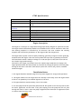
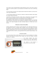
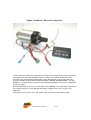
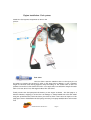
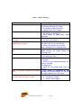
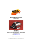
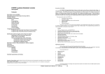
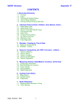
VT80 Instruction Manual
(Version 1.2/2012)
Torrent d’en Puig, 31.08358, Arenys de Munt, BARCELONA,Spain
Tel/Fax: +34 93 7950113
www.jets-munt.com
E-mail: [email protected].
© Copyright 2012, Jets Munt SL. All Rights Reserved
Welcome!
Congratulations on the purchase of your new Jets Munt VT80 gas turbine engine. Jets Munt
are dedicated to the design and production of engines to the highest standards of quality
and reliability to bring you the customer the very latest next generation engine designs.
The VT80 is the result of an intensive effort of design and tests by the Jets-Munt staff.
During the development period we made extensive use of the latest Computational Flow
Dynamics programs allowing us to optimise the engine performance characteristics.
PLEASE READ!
The Jets Munt SL responsibility is limited exclusively to the repair of the engine and
accessories which are outlined in the conditions of warranty.
Before unpacking the engine please read the manual, and agree to the conditions of
warranty.
Customer satisfaction is important to Jets Munt SL. Technical support is available trough
your local dealer and trough email.
Jets Munt S.L
Torrent d’en Puig 31
08358 Arenys de Munt
Barcelona. Spain
Web site: www.jets-munt.com
E-mail: [email protected]
Fax: +34 93 7950113
Legal and Disclaimer
The engine design and the contents of this manual are copyright by Jets Munt SL, Arenys
de Munt, Barcelona, Spain. All rights reserved.
This manual, the pictures and data are property of Jets-Munt and cannot be used or
reproduced in any way without written permission from Jets Munt SL.
Disclaimer
The VT80 engine is a sophisticated piece of machinery. Care should be taken at all times
when using the engine. It should only be operated by those with the appropriate skills and
knowledge to do so. This engine is not a toy. Incorrect operation or misuse can cause damage
to property and bodily harm operators, spectators and animals. Jets Munt SL accepts no
liability for any kind of damage which may occur.
Jets Munt SL assumes no responsibility for any errors contained in this document and is not
liable for any damages resulting from such errors.
VT80 Instruction manual V1.2
Pag: 2
It is forbidden the use of this engine outside Radio Control applications,
specially those that power vehicles that carry people.
Warranty
The warranty period for the VT80 is 2 years from the date of purchase, or 25 running
hours, whichever comes first. Warranty is valid solely for the original owner and is non
transferable upon resale.
Warranty includes all supplied parts, and is limited to manufacturing and material defects
only. Shipment costs, including packing and customs fees are not covered by the warranty
and will be always at owner expense.
Damage or defective operation covered under the warranty terms will be repaired and
tested at no cost the original owner (other than shipping expenses). Repairs not covered
under the terms of warranty will be carried out by Jets Munt SL or their appointed agents
after agreement of costs.
Before returning the engine or ancillary equipment for service of repair, please contact
first to your local dealer or Jets Munt central office to agree action and costs.
Please do not disassemble this engine or any other item supplied. You will breach your
warranty agreement and you will find it is a precision assembly which you will be unlikely to
re-assemble without considerable difficulty and specialist equipment. Simply slackening the
spinner nut of the rotor will immediately lose the delicate balance condition, without which
the engine may not run without damage to its rotating assembly.
This warranty is void if any one or more of the following conditions applies. In such a case
Jets Munt will accept no responsibility for any damage or any other consequence caused by
the VT80 operation.
1. The product has been subject to any form of operation whilst containing incorrect fuel,
oil, or fuel/oil mix.
2. The product is crash damaged, pump is blocked due dirt ingestion, electronics or pump are
flooded by fuel, connection leads are cut or lost its isolation and short-circuit, reverse
polarity on battery, etc.
3. Unauthorized maintenance or modifications have been made to any part of the product,
including the unlocking of the ecu and changing the manufacturer settings or any of the
items supplied has been dissasembled.
4. Parts have been damaged by ingestion of foreign objects (e.g. wires, sand, water etc).
5. The engine has been operated incorrectly.
VT80 Instruction manual V1.2
Pag: 3
6. The product has been misused, neglected or inadequately maintained.
7. Damage to the engine where blockages in the fuel system have occurred by unfiltered or
contaminated fuel.
Jets-Munt Representatives:
Check the current dealer list on our web page, www.jets-munt.com
Safety Notes
Please remember the engine is not a toy and has the potential to cause bodily harm to you
and others if misused. The VT80 is a sophisticated piece of machinery and should be
treated with a high level of safety when it is in operation.
The following guidelines should be read carefully and adhered to.
1. Always keep a CO2 or similar fire extinguisher of at least 2Kg of CO2 contents close
when starting and operating the engine
2. Always protect eyes and ears during the starting procedure.
3. Be aware of the extreme intake suction hazard, we advise the use of a suitable
commercial wire mesh Foreign Object Damage guard to protect the engine intake. Ensure
you have no loose items of clothing (ties, etc.) or equipment which can readily be sucked into
the engine intake, even from adjacent to the engine.
4. Always operate your engine in open air away from confined spaces as the engine exhaust
contains gases which can cause asphyxiation and nuisance smells.
5. Do not touch the engine whilst it is running. Turbines rotate at a very high rpm and the
engine casing and exhaust can reach very high temperatures. Ensure anything affected by
heat is kept well clear of the engine and exhaust during operation.
6. Never use the engine near to sources of flammable gases, liquids or materials.
7. Keep unauthorized persons, spectators, children and animals well away from the starting
area (at least 30ft or 10 meters away).
8. Always handle turbine fuel and oil with care as they are highly flammable. Store them in
appropriate labeled containers. Never dispose inappropriately. We recommend the use of
suitable disposable protective gloves for the mixing of turbine oil/fuel.
VT80 Instruction manual V1.2
Pag: 4
VT80 Specifications
Dimensions:
Weight:
Nominal thrust @ 15C and
sea level:
Max.RPM:
Idle RPM:
Idle thrust
EGT @ max rpm
Fuel consumption
Fuel/ oil:
Outer Diameter 90mm; Length: 240mm
950grams (engine only). 1075gr including pump and mounting
strap
80N
150,000 rpm
45,000 rpm
4N (0.8lbf)
550-650 ºC
0.29 l/min at 80N
Kerosene + 4% Oil See page 17 for oil types and percentages
Engine Description
The engine is a turbojet of a single shaft design specifically designed to power RC aircraft.
The engine starts automatically thanks to an installed electric starter situated in the front.
The starting sequence is controlled by an electronic unit that initiates the starting
sequence and controls the parameters of the engine within the design limits.
The engine uses a system of direct liquid preheating, ignited by a long life ceramic glow plug
situated inside the engine. After the initial preheat the liquid fuel is gradually introduced.
The fuel should contain a small percentage of oil and uses part of this fuel to lubricate its
two ceramic high speed bearings.
The fuel for the engine is provided from a fuel tank through a small electrical pump. The
engine speed between idle and maximum is controlled by varying the speed of the fuel pump
through an electronic controller called an ECU (electronic control unit), that is contained
inside the engine.
Installation Notes
1. The engine should be mounted using the strap mount supplied or an approved equivalent.
2. The signal cables from the engine must be carefully routed away from the engine intake
so there is no possibility of accidental ingestion of the wire.
3. Fuel pipe should be routed similarly clear of the intake
4. The fuel pump should be preferably mounted with the spindle in the vertical position with
the motor uppermost. In the event of any fuel seeping from the pump this will not pass
through the electric motor. Note the pump is supplied fitted with built in suppression filter
to reduce radio frequency noise.
VT80 Instruction manual V1.2
Pag: 5
5. The centre of the fuel tank should be mounted laterally, as near to the centre of gravity
(CofG) of the model as possible. This will minimize the CofG shift as the fuel is used during
flight.
6. Any air ducting to the inlet of the engine must have sufficient diameter of at least twice
of the engine intake diameter.
7. If an extended exhaust duct is required, it should be of sufficient diameter and strength
for optimum engine performance.
8. Extreme care should be exercised to ensure that no foreign object, loose parts of the
model or debris are allowed to enter the compartment where the engine is installed.
We recommend testing the engine on a test stand prior airframe installation.
You should have a clear idea of how to arrange the components needed to run the engine
inside the model. The main issue is the fuel tank, you will need to arrange the CofG in the
centre of the tank and adjust the receiver and ECU batteries to achieve the correct
location.
Electronic Control Unit (ECU)
The ECU integrated inside the engine is custom designed for the VT80 engine and must not
be changed for any other, as this may result in improper control of the engine. Your engine
has been set up and run with this ECU at the factory and the settings should be left as
default. The ECU plugs into your receiver throttle channel and is powered from the receiver
rechargeable battery. The ECU is pre-programmed and only requires simply setting to your
radio.
ECU Data Terminal
The System analyzer/data terminal plugs into the ECU via the lead supplied. The display
should be used only for starting and test running. This socket also doubles as digital
connection to a computer.
The System Analyzer does other
functions like a servo signal analyzer;
check the instructions on the Xicoy site.
The function of the buttons
described later in the “ECU setup”
VT80 Instruction manual V1.2
Pag: 6
is
Engine installation: Electrical connections.
Connect the power lead from the pump to the socket in the engine, and connect the battery
(not supplied) to the empty Multiplex socket. Connect the throttle channel from your
receiver to the socket in the exhaust side, orange lead pointing to the green connector.
PLEASE: DOUBLE CHECK THE BATTERY POLARITY BEFORE CONNECTING IT TO THE
ENGINE. A reverse polarity connection will immediately damage the electronic components
inside the engine.
Recommended battery is a LiPo of 7,4V and at least 2000mAh /15C. Optionally is possible to
use an A123 battery of 9,9V, although the engine is happier with 7,4V. 3s Lipo is not
supported.
The empty socket on the side of the intake is the connection of the data terminal.
VT80 Instruction manual V1.2
Pag: 7
Engine installation: Fuel system
Install the fuel system components as seen in the
picture:
Fuel filter
The fuel filter must be installed close to the input port on
the pump to prevent any particle to enter in the pump and to damage it. Use a suitable
length of the 4mm clear tubing supplied, keep the tubing on the suction side as short as
possible. Direction of flow inside the filter is not important, but should be always the same
after first use. Do not run the engine without the fuel filter.
Finally connect the fuel pump and the battery to the engine as shown. The fuel pump is a
delicate element, dropping it on the floor can damage it, always handle with care and install
using the provided mount, leave the motor part loose so that it don’t move in respect to the
pump part. Never disassemble the fuel pump, warranty from pump manufacturer will become
void.
VT80 Instruction manual V1.2
Pag: 8
It is strongly recommended that, after a new installation or modification on the fuel
system, to disconnect the fuel hose from the engine, routing it to a appropriate container,
and run the pump few seconds using the “pump test function” on the ecu so that some fuel
clean all the possible dirt particles that could have entered in the system during installation.
ECU (Engine Control Unit) Set Up
The ECU supplied is supplied programmed for the VT80. The engine has already been set up
and tested using the same ECU and pump supplied so there is very little to adjust in order
to get the engine running. Confirm you have connected the ECU input to the throttle channel
of your receiver, DISCONNECT the ecu battery, and connect the Data Terminal into the
ECU. Remove all rates, mixes and throttle travel settings in the transmitter. Before doing
any adjustment on the ecu, check that your transmitter is sending the correct signal by
checking the reading of “Pulse” in the data terminal. I should be between 900-1050uS at
STOP, position, between 1100 and 1300uS at IDLE position and between 1800 and 2200 at
Full Power position. Please note that these readings on the ecu are measured directly from
the signal received from your RC system, so you should readjust your transmitter if the
values read are outside that the ones suggested.
The setup assumes the use of a transmitter with manual trims.
If you use a TX with digital trims, is essential to use the switch in the TX
programmed for the function "Throttle cut", or “engine cut” which normally has the
effect of producing the “trim-down” function. Using a digital trim cause unstable idle,
and excessive delay in shutting off the engine in emergency.
Check your radio manual for this before you start. DO NOT use the digital trim in any
case.
Aligning transmitter with ecu
As the display does not photograph well we have reproduced the display readings as a green
box. Turn on the transmitter and receiver. The
Trim Low
T=020ºC
opening screen should show as below:
RPM 00000
PW 000
Note there are four buttons on the display, two
on the left and two on the right hand side. The left buttons move to the different screens
and the right buttons are used to change the values
Info
Run
stored. Press the second, left button and scroll
Start
Radio
through the menus until you find the one showing:
Press the (-) button and the ecu will show the “Radio” parameters menus. First screen show
graphically the current adjusts on the radio. Press the (-) button again to enter in the
menus to adjust the radio.
Transmitter
adjust
VT80 Instruction manual V1.2
Pag: 9
yes
Press the right hand button (+) to confirm that you
really want to program the radio. The screen will
change to:
Stick Up Trim Up
(Full power)
Ok
On your transmitter, raise first the trim to full
and next the throttle stick to full, in this order.
Ensure stick is firmly against the stop.
Now holding the stick against the stop, press
the right button (+) to store the signal from
your TX into the ECU.
The screen will now change to:
Stick Down
Trim Down
(Stop)
Ok
Move the trim (or switch the “engine cut”
switch to on) and throttle stick back to zero
and again press the right hand button (+).
The display will now change to:
Stick Down
Trim Up
(Idle)
Leaving the throttle stick in the minimum
position, raise the throttle trim to the full up
position or switch “Engine Cut” switch to off,
and again press the “+” button to store the
value into the ecu.
If you have done all steps correctly the LED
located directly above the throttle socket in
the ecu will light up flashing 2 times in the ECU
when the “Idle” command is received, meaning
that trim and throttle stick are set to idle
positions on the transmitter. If the ecu battery
is connected, a sound will be heard at same rate
as the Led blinks.
Lower your throttle trim and the LED will change to a single flash sequence indicating
correct reading of the transmitter engine shut off signal by the ecu.
VT80 Instruction manual V1.2
Pag: 10
On some Futaba transmitters, it has been found that the throttle channel the sense of
movement may require reversing (Servo reverse) and repeat the transmitter alignment.
Correct reading of throttle % by the ecu can be verified in
Pulse=1000uS 0%
the second screen of the data terminal, percentage of the
Battery: 7,2V
throttle position is shown on, 0% in the position of engine
stop (trim and stick down), 100% with stick/trim full up and
between 10% and 30% at idle.
This now completes your radio setup and should only need doing again if the radio settings
are changed.
Failsafe:
Never fly with the failsafe set to “hold”. It is strongly recommended that you setup your
radio system with the correct failsafe settings. In some countries is mandatory that the
engine stops in 2 seconds in the case of a failure of the radio link.
To program correctly the failsafe on your radio:
1) Adjust the travel of the throttle channel from -100% (stop position) to +100%
(full power)
2) Adjust the ecu to your radio as described above.
3) Adjust the failsafe position of the throttle channel in your radio to a -125%.
If all is correctly adjusted, the ecu will stop the engine immediately when receive the STOP
signal (-100%), but if the signal received is Failsafe (-125%) the ecu will set Idle power
during 2 seconds, and, if after these 2 seconds the Failsafe condition persist, will shutdown
the engine.
Once you have the radio programmed, you can check it by setting the throttle to the
different positions, including switching off the transmitter; in this case the “failsafe”
reading should be displayed.
There are many more parameters that can be modified in the ECU, but we have specifically
programmed your VT80 ecu with the optimum settings, further adjustment should not be
required and can only be carried out by Jets Munt SL or your authorized dealer.
Preparing the engine for running.
A suitable platform/table/workbench is now required to clamp the test stand onto. Make
sure this can be easily transported outside and weight enough to ensure it cannot be blown
over by the thrust of the engine.
VT80 Instruction manual V1.2
Pag: 11
Select a clear area for running – keep clear of areas with loose leaves, sand or other debris
that could be picked up or drawn towards the intake. Ensure the fuel tank is position well
clear of the exhaust area and secured.
Important notes for kerostart engines.
PLEASE READ
The kerostart system used on this is a reliable and well tested that produce very smooth
and trouble free starts.
However, extra care and attention must be paid when starting a kerostart engine.
The main difference between gas and kerosene is that in the case of a failed ignition, the
gas dissipates quickly on the air and don't keep inside the engine. Kerosene is liquid and, if
unburned, will pool inside the engine and stay there forever. The engine can hold a big
quantity of kerosene inside. This kerosene will be ignited on next successful start up and
will be pushed to the exhaust as soon as the airflow inside the engine is sufficient, and will
be ignited in the exhaust, causing a hot start (in extreme cases a big fireball) that surely
will not hurt the engine, but can destroy the model.
To prevent this:
-During the start-up listen to the engine sound to check for positive sound of
ignition, check looking from the exhaust that the kero is burning, or check for a increase in
exhaust temperature in the data terminal. A small plume of white smoke from the exhaust
means that the fuel is not burning. The fuel is pooling inside the engine. Abort immediately
the start.
-Double check that the engine is not flooded. A extra security measure is to place a
manual valve between the last fuel tank and the pump intake line, to prevent that during the
process of filling the tanks or during storage, some fuel can arrive to the engine.
-After a failed start, or whatever condition that could cause that fuel be collected
inside the engine (i.e. extra priming), ALWAYS empty the engine of fuel by tilting the
engine nose down. Fuel will exit trough intake. Do not tilt upwards; due at the internal engine
construction the fuel cannot exit trough exhaust.
Another big difference between gas start and liquid start is that the kerosene can keep
slowly burning during long time inside the engine. This situation usually happen during an
aborted start, the start-up sequence is aborted by the user or automatically before the
engine arrive to idle. This can cause that the kerosene inside the engine keep burning for
long time, and could destroy the engine or the model. IF A STARTUP SEQUENCE IS NOT
COMPLETED, ALWAYS CHECK FOR FLAME INSIDE THE ENGINE. If there is flame, then
set full throttle for over 3 seconds to engage the starter and blow out the flame. USE
SHORT BURSTS OF STARTER. Using the starter for long time can destroy the starter
motor. In the case that the start-up procedure has been aborted due at starter failure,
VT80 Instruction manual V1.2
Pag: 12
then it will be necessary to apply the CO2 fire extinguisher. A white smoke from the engine
is a good indication here; mean that there is no fire inside.
First engine runs.
•
Confirm your test stand is securely fixed to a bench or heavy table. Keep your ear
defenders within easy reach and a CO2 fire extinguisher handy. VERY IMPORTANT ON
•
•
•
•
Fill the fuel tank. Do not forget to filter the fuel, and to mix the oil.
Confirm all batteries are freshly charged and connected up.
Check there is a temperature reading on the data terminal.
Ensure the running area is clear of onlookers – especially the prohibited zone of a 10
metre radius 180° arc from engine centre around the rear
Verify that the fuel tube is full of fuel and purged of all air, if not, carry out the
fuel prime sequence as described here.
KEROSTART ENGINES.
•
Priming the fuel system:
Fuel line need purging of all air after initial installation. Take extra care when priming them,
ensure fuel is primed only up 5cm before to reach the engine; too much fuel inside engine
will cause excessive flaming during start sequence.
Priming is achieved by a special menu on the ecu. Set the trim to low and go to “Info” menus
and next to “Pump test”. Click on “on” /”off” to start/stop the pump manually. Please
observe fuel line to engine very carefully and push the off button to shutoff as soon as fuel
reaches engine..
IMPORTANT: The prime procedure should be done only to fill the fuel tube and filter
in the case of a first installation or in case of disassembling of the tubes. Do not run
the prime function so that the engine becomes flooded by fuel, as this will cause an
uncontrolled fire at next startup.
Starting the engine.
Set the throttle stick down and the trim up. “Idle” - Confirm that the LED in the ecu is
blinking in a sequence of 2 blinks and the screen shows "Ready" - !Ready to start!.
Move the stick to full throttle and then back to idle again. The Ecu will begin the startup
sequence as described below:
First the internal glow plug will be energized. After 3 seconds, the starter will be powered
up to have the rotor turning at slow speed (2000- 3000 RPM).
VT80 Instruction manual V1.2
Pag: 13
Once the rotor is at speed, the pump and solenoid valves will be energized in pulsating mode.
Few seconds later the kerosene will ignite and the exhaust temperature will begin to
increase. The rpm and pump power will increase automatically. During this phase the data
terminal will display “IGNITION”.
When the ignition is detected, the data terminal reading will change to “Preheat”, during
this phase the fuel will be routed to main injectors and the speed of the rotor will be
progressively increased to 12,000 RPM.
Once this phase is finished, the reading will be “FUEL RAMP”. In this phase the engine
receives fuel only trough its normal fuel input and internal glow plug will be disconnected.
The fuel flow and starter power will be increased automatically to increase the RPM up to
idle RPM. Before arriving to idle the Ecu will automatically disconnect power to the starter.
When the rotor speed reaches idle, the screen will change to “running” and the engine speed
is stabilized.
The engine is running!
Control of engine power/rpm is now handed back to the transmitter and controlled by the
position of the throttle stick. Increase/decrease the throttle slowly, verifying that the
engine accelerates/decelerates. Take special care around the engine intake; keep your
hands at a safe distance along with any other objects as they can be easily ingested.
Engine shut down procedure:
To shut down the engine lower the trim and the stick. Is recommendable that before
shutting down the engine please restrain the model then raise the throttle stick to
approximately 25%, allowing temperatures to stabilize for around 5 seconds before carrying
out the shutdown procedure.
WHAT TO DO IN THE CASE OF AN EMERGENCY
During the start sequence the Ecu will be in charge of everything, controlling temperature
and RPM. The only thing the user can do is to abort the sequence by lowering the trim in the
case that something abnormal (excessive flames in the exhaust, etc).
If a problem is detected, first:
Move the trim to the low position to abort the sequence.
If there is a fire in the engine and the problem is because the starter has failed or the
engine is seized (not turning), IMMEDIATELY APPLY THE FIRE EXTINGUISHER through
the intake side of the engine, never trough the exhaust.
If there is a fire, but the rotor remains free to spin and the starter is OK, raise the trim
and stick to the full power position for 3 seconds, this will connect the starter manually to
ventilate the engine and extinguish the fire. The throttle channel acts as a starter switch.
USE SHORT BURSTS OF STARTER. Using the starter for long time can destroy the
starter motor.
VT80 Instruction manual V1.2
Pag: 14
List of ECU message codes
Here is a list of possible messages shown on the data terminal screen and their meaning.
TrimLow: Indicates that the signal received from the transmitter corresponds to the
lowered trim, that is to say, engine OFF.
Ready: Indicates that the engine is ready for starting, and that the transmitter signal
corresponds to IDLE, (LED lit twice)
StickLo!: This indicates that the throttle stick is in a position above IDLE, the engine will
not start with the stick in this position.
Glow Test: Verification of glow plug
StartOn: Test of the starter
Ignition: Gas ignition phase.
Preheat: Phase of heating of the combustion chamber after detecting
the ignition.
FuelRamp: Phase of acceleration until idle speed.
Running: Engine working correctly, pilot have full control of engine power.
Stop: Engine off.
Cooling: Starter operating to cool the engine.
GlowBad: Defective or disconnected glow plug.
StartBad: Defective starter, insufficient RPM reached during start, RPM sensor damaged.
Low RPM: Engine had been shutdown because the speed has fallen below the minimum.
HighTemp: Excessive temperature
Diagnoses:
During engine operation the Ecu measures and stores all the engine operating parameters
recorded during the last the 51 minutes of operation. These measures can be downloaded
later to a PC to study the behavior of the engine in flight and to diagnose any possible
problems.
Also, after each cycle of operation, the Ecu stores the last cause of shut down and the
values of RPM, temperature and pump power. In order to access these measures, it is
necessary to shut down and power-up the Ecu. Set the trim down (trimLow) and push the
left button on the display. The Ecu will show the cause of last shutdown and the parameters
values at the moment of shut down. These are as follows:
Diagnosis messages:
UserOff: The engine has been shut down because it has received the shut down command
from the transmitter.
FailSafe: The engine has been shut down because of loss of the control signal from the
transmitter. After 0,5s of detecting a loss or invalid RC signal, the ecu sets engine power to
idle, and if after another 1,5seconds a valid signal is still not received the engine is shut
down.
LowRPM: The engine has been shut down because the RPM has dropped below a minimum.
Cause could be lack of fuel, air bubbles, problem with the batteries, or defective RPM
sensor.
RCPwFail: Lack of power from the radio receiver.
VT80 Instruction manual V1.2
Pag: 15
Other useful information and installation tips:
Fuel System
Always use appropriate containers to store fuel.
It is advisable to install an anti bubble system to
the fuel supply circuit. The simplest one is a felt
filter clunk installed into the fuel tank. This helps
maintain consistent fuel flow and greatly reduces
the possibility of air getting into the suction side
of the pump circuit, which could cause stoppages.
To prevent the felt element sliding out of position a
washer is fitted between it and the feed tube – as
seen.
A BVM UAT is another contemporary
method of reducing the possibility of air
bubbles in the engine fuel line. This is a
very important aspect of the operation of
any turbine engine.
Use a appropriate adapter for the 6mm
tube output of the UAT to the 4mm in
the inlet side of the fuel pump, direction
of fuel flow is clearly shown at the top of
the pump. The clear 4mm tubing is used on
the pressure side of the pump. Clear
tubing helps identify and locate any potential future problems with air leaks.
The fuel pump and ECU can be mounted simply with a pair of tie wraps and/or Velcro. The
best orientation for the fuel pump is vertical. It is important to ensure any fuel seepage
does not reach the motor brushes. The fuel feed from the pump to the engine should have
sufficient length of the clear tubing fitted to allow the fitment of the electronic fuel shutoff valve and the valve should always go on the pressure side.
When making any fuel or gas line cuts use a sharp blade to make and cut squarely. The fuel
filter provided should be installed in an accessible place for regular inspection, close to the
intake port of the pump.
Fuel and Oil
1. Use CLEAN well filtered Jet A1 or kerosene fuel which is available from most airports, or
paraffin (K1) used for greenhouses available from most hardware stores.
2. Ensure the fuel is clean and filtered at each stage of mixing and transfer to the model
fuel tank.
Please note the importance of using clean fuel. Failure to do so will result in blockages of
the fine fuel injectors in the engine or blockage of the engine lubrication system and
subsequent bearing damage
VT80 Instruction manual V1.2
Pag: 16
3. Ensure the fuel is free from moisture (water is heavier than fuel and will settle at the
bottom of the container).
4. Use good quality oil:
-> Aircraft turbine oils e.g. Aeroshell 500, Exxon 2380, Mobil JetOil II. Mix at 4%
-> Mobil DTE Light turbine oil. Mix at 5%.
-> 2 stroke 100% synthetic oil with a specification JASO FC or better. Mix at 3%
-> Recommended: 3% Mobil DTE Light + 1% 2T Oil (JASO FC)
DO NOT USE TCW-3 oil. TCW-3 is a specification for marine oils and guarantees that it is
not poisonous for aquatic life, however not guarantee the oil quality for turbojet engine use.
Important note regarding the 2T oil: The engine can use 2T oil, but the different oil
brands use different contents of additives to protect the mechanical parts from rust
during inactivity periods. This is good for engine protection, but some oils become too sticky
when cold, preventing the starter motor to turn the rotor at correct speed, causing a
startup failure (Bad Starter message) or damage to the ecu or starter motor after
repeated abuse. We strongly recommend to use turbine oil or our recommended oil mix if
you find that the rotor become sticky on cold conditions.
5. The fuel must be mixed with oil in the recommended ratio. Too little oil will shorten the
bearings life. You can use higher content of oil (5-6%) without any problem for the engine to
share the same fuel with other engines.
Please remember to always handle fuel and oils with care! Avoid all direct contact with skin
– in case of contact wash all affected areas with soap and warm water immediately.
Feed Pipes
All the pipes must be Polyurethane or nylon as provided by Jets Munt or Tygon (like the
ones used by gasoline engines). Do not use Tygon on the pressure side of the fuel pump.
Silicone tubing must not be used anywhere in the installation as it is dissolved by fuel and
oil. If in doubt, take a small piece of tube and submerge it in kerosene for a few days and
verify that its characteristics have not changed.
Maintenance
1. Always keep the engine and its accessories clean and dry.
2. Regularly check wires for chafing or insulation breakdown etc.
3. Regularly check fuel pipelines for chafing and /or leaks at joints.
4. Check the engine and mounting for loose fittings and secure if required.
5. Ensure the fuel system is kept free from dust and dirt inclusion and that fuel is carefully
filtered.
VT80 Instruction manual V1.2
Pag: 17
Running Time Counters.
Using the second left hand button, scroll through
Timer:
Tot:0000m
the menu’s to the INFO menu.
Last: 000s
Cy:000
This screen contains a timer which shows:
The total running time of the engine in minutes (Tot),
The time in seconds of the last engine run (Last)
The total number of starts (cycles - CY).
Use this screen to keep track of your total running time and starts.
A extra timers is provided, called Service Timer, to keep track of the service intervals, it
will be reset when the engine is serviced in regular maintenance.
Extra ECU functions.
The ecu provides several menus that allow doing some tests and personalizing some settings,
like:
-Adjust the thrust/throttle curve (Linear, Expo, Intermediate)
-Test the starter, Glow Plug, valves and Pump.
-Check the failsafe counter (time and pulses of wrong RC signal)
-Reduce the maximum power
-Increase the Idle Rpm.
-Adjust the glow plug voltage. The engine come from factory with this voltage
adjusted for reliable starts and long life of the glow plug element. Increasing the voltage
beyond the necessary will cause the failure or shortening of the life of the element. Do not
change the voltage, please contact to Jets Munt first.
-Adjust the pump power at startup. The fuel flow during ignition phase must be
finely tuned for each engine/pump combination, and this is done at factory during test. In
the case that after some run time the pump become loose and the starts become too
aggressive, reduce the value by 2 units at time until normal starts are reached again.
Engine Kill Switch
It is good practice, and in some countries mandatory, to have
an alternative means of shutting off the engine in
emergencies independent of the ecu. A simple method to
achieve this is by putting a switch in the battery line to the
ECU, operated by a mini servo mounted to a ply plate. The
plate is drilled for a miniature toggle switch actuated by the
servo arm – position it so it can only be reset by hand. The switch is wired in series with the
positive (red) battery wire to the ECU. The servo should be connected to a channel which is
operated by a switch on your transmitter so it can be operated quickly. The servo travel
should be adjusted to ensure it is not stalled at either position.
VT80 Instruction manual V1.2
Pag: 18
VT80 Trouble Shooting
PROBLEMS
There is no reading on the screen
SOLUTIONS
1. Disconnected receiver or the
ecu/receiver batteries are empty
2. The display is badly connected
3. Problem in the ecu or display
The kerosene does not ignite
1.. Check fuel flow.
2. The battery is discharged
4. Glow voltage or pump power needs
adjustment
There is little increase of RPM when the
1. There is air in the line of fuel
fuel ignites
2. The filters are blocked
The engine reduces the power of it is
1. The ecu has detected temperatures
stopped during starting
over 800ºC due to too slow starting
2. There is low battery or air in the
tubes- Therefore let it cool and retry
Engine does not accelerate to maximum set 1. There is insufficient fuel flow or air
rpm
bubble entering the engine during the
initial start up.
The engine loses power in flight
1. The ECU battery is empty: recharge
2. The filters are dirty
The engine stops in flight
1. The fuel level is low and/or there is air
in the pipes
2. There is a poor connection between the
battery and pump
3. Interference
4. Check the “last power down” cause on
the ecu
There is excessive vibration and unusual 1. The engine is unbalanced by the
noise
ingestion of a foreign object. Do not use
the engine and send it in for service.
During startup the rotor spin at low speed
1. Incorrect oil used on last run.
and “Start Bad” message is issued
2. Low battery voltage
3. starter clutch slipping
VT80 Instruction manual V1.2
Pag: 19
VT80 Log
Owner____________ Serial Number:____________ Purchase Date__________
Start
No.
Date Model Place Engine
Time
Flight
Time
Remarks
VT80 Instruction manual V1.2
Pag: 20