1
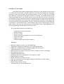
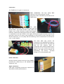
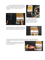
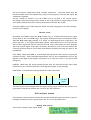
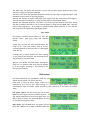
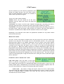
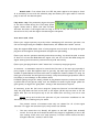
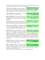
FADEC system - Autostart 06
Users Guide.
Parlament, 13. 08358, Arenys de Munt, Barcelona,Spain
E-mail: [email protected]. Fax: +34 933 969 743 web: www.xicoy.com
© Copyright 2007, Xicoy Electronica SL. All Rights Reserved
Manual contents & design: Gaspar Espiell
Welcome!
Congratulations on the purchase of your new FADEC 06 controller. Xicoy are dedicated to
the design and production of electronic controllers to the highest standards of quality and
reliability to bring you the customer the very latest next generation designs.
The FADEC 06 is the result of an intensive effort of design and tests.
PLEASE READ!
The Xicoy Electronica SL responsibility is limited exclusively to the repair of the FADEC
and accessories which are outlined in the conditions of warranty.
Before using the controller please read this manual and agree to the conditions of
warranty.
Customer satisfaction is important to us. Technical support is available trough your local
dealer and trough users forum www.xicoy.com/foro.
Legal and Disclaimer
The FADEC design, firmware, PC soft and the contents of this manual are copyright by
Xicoy Electronica SL, Barcelona, Spain. All rights reserved.
This manual, the pictures and data are property of Xicoy and cannot be used or
reproduced in any way without written permission from Xicoy SL.
Disclaimer
Gas turbine engines are a sophisticated piece of machinery. Care should be taken at all
times when using these engines. They should only be operated by those with the
appropriate skills and knowledge to do so. Incorrect operation or misuse can cause damage
to property and bodily harm operators, spectators and animals. Xicoy Electronica SL
accepts no liability for any kind of damage which may occur.
Xicoy Electronica SL assumes no responsibility for any errors contained in this document
and is not liable for any damages resulting from such errors.
It is forbidden the use of this equipment outside Radio Control
applications, specially those that power vehicles that carry people.
Warranty
The warranty period for the FADEC 06 is 1 year from the date of purchase. Warranty is
valid solely for the original owner and is non transferable upon resale.
Warranty includes parts and labor and is limited to manufacturing and material defects
only.
Damage or defective operation covered under the warranty terms will be repaired and
tested at no cost the original owner (other than postage and packaging). Repairs not
covered under the terms of warranty will be carried out by Xicoy Electronica SL, or their
appointed agents after agreement of costs.
Before returning any equipment for service of repair, please contact first to your local
dealer or Xicoy central office to agree action and costs. Please check the “Limited
warranty conditions” at the end of this document for details.
Description of the FADEC.
The FADEC (Full Authority Digital Engine Control) is a total system for the control
of a model gas turbine engine. Its main function is to control and regulate the fuel pump,
providing to the turbine engine the necessary amount of fuel for safe and controlled
operation, and to operate the ancillyary devices for starting. The FADEC measures the
exhaust gas temperature, the relative position of the throttle stick and the rotor speed.
It monitors all of the controls necessary to guarantee that the engine stays between the
user defined parameters of operation, also providing failsafe shutdown of the engine when
it has detected any important anomaly. In order to make this assessment, the FADEC has
a rpm sensor, a thermocouple input, a throttle servo input, power connections for the fuel
pump, starter, glow plug, fuel and gas valves and the battery and a digital (RS232) serial
port to program and read the data in real-time to a PC.
The measurements made by the FADEC are:
•
•
•
•
•
•
•
Temperature of the exhaust gas
Battery voltage
Barttery current
Width of the throttle pulses from the radio transmitter
Engine rotor RPM
Engine run time.
External analog signal (airspeed sensor)
Features:
•
•
•
•
•
•
•
•
•
•
•
•
•
•
RPM input: Magnetic sensor up to 250.000 R.P.M.
Temperature range up to 1000ºC using a "K" type thermocouple
PWM control of 8192 levels for pump, glow plug and starter motor.
Adjustable power for the starter motor
Build-in electronic brake for the starter motor to help the clutch to disengage.
Blown glow-plug detector
Adjustable glow-plug power
Glow-plug temperature independent of the battery voltage
Elapsed engine run timers
RS232 interface to interface to a PC.
Black box function. Record the engine measures each 0.5sec up to 52 minutes.
Radio link error counter
Battery usage counter in mA/h
Test functions for all connected devices.
Connections:
The FADEC have 3 types of connections:
Power connections: Two high quality MPX
connectors carry all the power current.
Each power lead is identified by the label on the
FADEC body.
The
upper
MPX plug provides the power to the glow plug and
starter motor. Use 0,5mm flexible cooper lead if the
length is up to 0,5m, and 1mm if higher. Both negative
leads are connected to same place inside the FADEC, so
it is possible to use only 3 leads to the engine, sharing the negative between starter and
glow plug. Take care of doing a neat installation to avoid short-circuits, specially in the
starter connection, it is very easy that the soldering in the red lead touch to the starter
cover in some engines.
The lower MPX plug provide the
connection to the pump and the battery.
Use 0,5mm cooper lead for the pump and
1mm for the battery. Keep all
connections well isolated between them,
and be sure to not reverse the battery
polarity, the fadec will be burned out
immediately. The battery
minimum
voltage is 7,2V and maximum 8,4V.
DATA Connection:
One 8 pin socket, placed on the top of the FADEC,
provides the connectivity to the handheld data
terminal or a PC.
Signal connections:
8 JR type receptacles provide the connection to
the solenoid valves, RX and sensors
Connect the RPM sensor and thermocouple on
its respective sockets, in the orientation that is shown
in the colored labels on the fadec. If necessary both
leads can be extended using good quality servo
extensions.
Connect the throttle lead
from the RX in its place, in the
upper position. Lower socket is
ready for a second servo signal but
not used on present firmware
Airspeed (pitot) sensor, if used, must be connected as
shown in the picture, in the upper position. Please note
that in early (Nades) units the label is not correct.
The last two sockets are used for the connection of the solenoid valves. Upper position for
the gas/keroburner solenoid and the lower position (as shown in the picture) for the main
fuel valve.
About solenoid valves, please note that they should
be of the same rated voltage as the battery and
consume less than 0,5A.
Using and Programming the FADEC:
All the programming and measures are done trough the data terminal. Once the
FADEC is programmed , it is not necessary its use, and it is not recommendable to leave it
inside the airplane to minimize the risk of interferences.
The data terminal have a 16 character LCD screen
and 4 buttons.
The first two buttons on the left side allow to
move trough the menus, and the two buttons on the
right side allow to change the data.
Main screen, as shown in the picture, give to the
user that main readings from the engine. These are
the FADEC status, the EGT (temperature), RPM
and pump power.
In the case of a error, this screen changes to the error
screen each 2 seconds
Pressing the second button from the left
(Menu Up) the second informative screen is
shown. In the first line you have the
measure of the pulse width received from
your RC system, and the relative stick
position. Second line show the voltage of
the battery and the software version. If
the current drawn from the battery is
higher than 0,5A, then the FADEC display
the battery voltage and the battery
current in Ampers.
Next menu let you to choose in four submenus, selected by pressing the button under of
each option.
Start: Jump to the parameters used on
startup
Info: Information and test menus
Radio: Adjust the radio throws
Run: Set the parameters used during engine
run.
It is recommended that the first adjust be the one of the radio:
Aligning the transmitter with the FADEC
Turn on the transmitter and receiver. Using
the “menu up” and (-) buttons move to the
“Radio” menus. First screen will be this one:
If you are sure that you want to modify the
radio settings then press the right hand
button (+) and the screen will change to:
On your transmitter, raise the throttle
stick and trim to full.
Ensure stick is firmly against the stop.
Now holding the stick against the stop, press
the right button (+) to set the value into the
FADEC.
IMPORTANT NOTE: Pressing any other
button the setting WILL NOT be stored.
The screen will now change to:
Move the trim (or switch the “engine cut”
switch to on) and throttle stick back to zero
and again press the right hand button (+).
The display will now change to:
Leaving the throttle stick in the minimum
position, raise the throttle trim to the full up
position or switch “Engine Cut” switch to off,
and again press the “+” button. The FADEC will
store the current position as IDLE.
If you have done all steps correctly the green
LED located directly above the data terminal
socket will light up in the ECU when the “Idle”
command, (trim and throttle stick set to idle positions on the transmitter).
Lower your throttle trim and the green LED will go out indicating correct reading of
the transmitter engine shut off signal by the Fadec.
On rare occasions, usually when using a Futaba transmitter, it has been found that the
throttle channel sense of movement may require reversing (Servo reverse) and repeat the
transmitter alignment.
Correct reading of throttle % by the FADEC can be verified in the second screen,
percentage of the throttle position is shown on, 0% in the position of engine stop (trim and
stick down), 100% with stick/trim full up and between 10% and 30% at idle.
This now completes your radio setup and should only need doing again if the radio settings
in the TX are changed.
Throttle curves.
By default the FADEC control the RPM in linear way, i.e, at half stick position the engine
turn at half of the rotor RPM range. Jet engines develop the thrust in exponential mode,
thus half RPM means approximately ¼ of thrust. On small engines with a high idle to full
power rpm ratio, or in a high drag/low power planes, often only the last 1/3 of the throttle
stick produce significant thrust, with the low half stick travel being not used. Although
that with current digital TX the pilot can modify the throttle curve to suit his needs, from
version 5.48 three throttle curves have been added to simplify the setup for most of the
installations:
FULL EXPO: Mean linear RPM, it is the default setting and the mode used for all previous
software versions. Thrust develops exponentially, and it is the recommended curve for big
engines or/and high thrust/weight ratio planes, as it ease the control in low power used
during taxi.
LINEAR: Mean that the thrust develop linearly with the throttle setting. Could cause
difficult taxi, as it would be difficult to fine adjust the power at low settings.
HALF EXPO: A intermediate setting between the other two modes.
Stick position
MODE
FULL EXPO
HALF EXPO
LINEAR
0% (Idle)
Idle thrust
Idle thrust
Idle thrust
25%
6%
16%
25%
50%
25%
38%
50%
75%
56%
66%
75%
100%
100%
100%
100%
% of total
thrust
Throttle curves can be changed while the engine running, so you can leave the throttle at a
given position and switch between the curves to see the difference.
Info and test screens.
This submenu contains several screens that provide useful information and tools to get the
maximum information on your system and to aid to correct any malfunction.
Running Time Counter.
This screen contains a timer which shows:
The total running time of the engine in minutes (Tot),
The time in seconds of the last engine run (Last)
The total number of starts (cycles - CY) .
Use this screen to keep track of your total running time and starts.
Battery used Counter.
This screen display a mAh counter which shows
the current used from the battery. The counter
can be set to zero by pressing the (+) button.
The use of this screen is to know the capacity of
the battery used in a flight or in a session to decide when its time to recharge it.
NOTE: The precision of this counter is +/- 10%.
RX errors Counter.
The FADEC detect a error on the signal
received from the RX when this signal is absent
or outside from the valid window programmed
during the Radio setup. The standard on RC systems are that servos should receive 50
control pulses/second from the RX, and each pulse duration should be between 1000 and
2000 microsecond.
First line on this screen display the count of the pulses received that are shorter than the
“STOP” signal or larger that “Full power” signal received by the FADEC during the Radio
setup.
Second line shows the duration of the wrong signal, and this include the time that no
pulses have been received.
On PCM systems, the signal issued by the RX during a radio link failure depends of the
programation of the PCM settings in your TX. If you program your PCM failsafe settings
to “hold” or set the throttle position during failsafe in a valid position for the fadec (signal
between STOP and FULL POWER) the fadec will not detect any radio problem, so it don’t
will count any error. Our recommendation is to program the failsafe of your TX to issue a
signal to the throttle channel of less value than the STOP signal. I.e , if your STOP
position is –100%, set the throttle failsafe to –125%. This will assure that the fadec will
recognize a failsafe condition, record the time, and stop the engine after 2s if the radio
link is not recovered. This last condition is obligatory in some countries and 100%
recommendable. Never fly your plane with the failsafe set to “hold” in the throttle
channel.
Airspeed.
If the airspeed sensor is connected to
the FADEC, it will detect it at power-up and
enable this screen. On first line it is possible to
set the maximum airspeed allowed for the
plane, between 32 and 250mph (50 to 400km/h), or OFF (no limit). The fadec will reduce
automatically the throttle to keep the airspeed at or below the maximum. Please note that
the fadec only can reduce the throttle, it never will give more power than the one set by
the pilot trough the throttle command.
Second screen show the maximum airspeed reached on last flight in mph and km/h. This
maximum is set to zero on next engine start.
Setting the throttle to higher than 50% (with engine off) the second line will change to
“Current airspeed” to allow you to test the operation of the airspeed sensor.
Besides the maximum airspeed, the fadec record the current airspeed each 0,5s during
the last 51 minutes and store it in its internal memory, along with the RPM, EGT, Throttle
position and pump power. It is posible to download later these measures to a PC and see
the airspeed of the plane during all flight phases.
Test menus
The Fadec provides several menus to test the
starter motor, glow plug, pump and solenoid
valves.
These test screens are only available when the
Fadec is on “Trim Low” status, that is to say,
recently powered up and receiving a STOP signal
from the TX.
Pressing the (-) button (under the “ON” reading
on the screen) will energize the selected device
and pressing (+) will shut down.
Special care should be taken when testing the
pump, as it is possible that some fuel be pumped
in to the engine, flooding it, and causing a hot
start on next startup
RUN menus:
On these submenus the parameters used for the
engine during normal run can be modified.
Note that in some of these menus could not be
available in your unit if your fadec belong to a production engine where the engine
manufacturer have set these values at factory and restricted to the users to modify
them.
Full power speed: On this screen you can set the
RPM that the engine will run at 100% throttle. If
the engine manufacturer have set a upper limit, you
will be able to reduce the maximum speed, but not
to increase it beyond the limit.
Idle speed: Set the RPM that the engine will run
when the FADEC receive IDLE command. While the
engine running the fadec will adjust the rotor speed accordingly the throttle position in a
closed loop system.
STOP speed: Set the minimum RPM that the engine is allowed to run. The FADEC will
shutdown the engine if the rotor speed is below this setting.
Start/Min
temperature: Set the minimum
temperature that the engine is allowed to run, and
in manual start operation, sets the temperature
from wich the pump begin to run.
Maximum
temperature: Set the maximum
temperature that the engine is allowed to run. The
FADEC will reduce the acceleration rate if the EGT
aproaches to maximum and will reduce the pump power if necessary to keep the
temperature below the maximum, but it don’t will cut the engine if the temperature is too
high, it will try always to keep the engine running by reducing the fuel flow .
Acceleration delay: Set the acceleration time on
the engine. Higher values, longer acceleration
times. The real acceleration time is calculated
using a complex algorithm that take in to account this value, temperature, current RPM,
commanded RPM, and the tendency of EGT and RPM.
Deceleration delay: Similar to the acceleration,
but used during throttle down. Higher values mean
slower deceleration.
Stability delay: When the engine is running at
constant throttle setting, the FADEC is adjusting
continuously the pump power so that the rotor RPM
mach exactly with the throttle signal. The speed of witch the fadec adjust the pump
power is set by this parameter. A value of 100 usually is the best for all engines. A too low
value can cause instability on the RPM.
Pump Limit: The Fadec can give to the pump the full
battery voltage, but in most cases the voltage
needed for the pump is only a fraction of the full
battery voltage. Limiting the pump give a much smoother control of the engine and
prevents that the pump could receive excessive voltage in the case of a problem in the fuel
circuit, a clogged filter for example. This excessive power will cause a high pressure on
the circuit that can cause leaks or blown tubes.
Modifying this parameter is similar to reducing the battery voltage, so the accel and decel
times will be modified. The recommended adjust of this setting is to set it to 1020 (no
limit) , run the engine, check and annotate the Pw of the pump displayed on the first
screen when the engine is running at full power and then use this value as pump limit,
increasing it in a 10%-20% to give a bit of margin for weak batteries and pump wear. Once
the new value set, adjust the accel and decel delays for best engine handling.
START menus:
On this submenu you will find the parameters used
during the engine startup. Like the “RUN” menus,
some of these parameters could be not available in
fadecs used in production engines.
There are 3 start modes available:
-Manual, where the user should do all the start
sequence, and the fadec only control the pump and
the fuel valve
-AUTO-Gas: The fadec do all the start sequence automatically controlling the starter,
glow plug, pump and valves, using auxiliary start gas (propane-butane) for ignition.
-AUTO-Kero: The fadec do all the start sequence automatically controlling the starter,
kerosene burner, pump and valves, using kerosene for ignition. This menu only appear if
KeroStart is enabled in the FADEC and the software version is 5.41 or higher.
Depending on the selected start mode the parameters available are only those related
with the selected mode.
Manual Start mode:
In order to start the engine in manual mode, the user must first raise the transmitter
throttle trim and leave the throttle stick in idle/minimum position. The green Light
Emitting Diode (LED) on the FADEC illuminates, and the status screen show “Ready”
indicating the system is "ready for start". Once in this position, the operator must 1)
turn/spin up the engine with the starter motor / blower etc, 2) open the butane/propane
gas, and ignite it. When the FADEC registers an exhaust temperature higher than the
programmed start/minimum temperature and the rotor turning, the “Fuel Ramp” begin, the
LED begins to blink and the system begins to pump fuel to the motor, raising the fuel pump
power slowly until the idle speed is reached. This final condition is signaled by the system
extinguishing the LED and the “Running” word on the status screen. The user now have
control of the engine power trough the throttle stick. Seting the trim to LOW the engine
will be shutdown.
Parameters used in “manual start” mode:
Pump Start point: Sets the power of the pump
when it is started at beginning of the fuel ramp.
The FADEC have the ability of to automatically adjust the pump power to start it at the
lowest possible speed, independently of the battery voltage and pump roughness. Also the
user have the possibility to adjust the minimum pump power manually.
AUTO mode: The values of “Pump start point” from 0 to 8 are in AUTO mode.
This means that the FADEC will adjust itself the pump power to start it slowly. The usual
value for a unknown engine is AUTO+2, but after the first start you can increase or
decrease the fuel flow if needed.
Manual mode: From values from 9 to 255 the power applied to the pump is fixed.
It is necessary to test with the selected pump and battery the right value to have the
pump to start at the desired speed.
Pump Start ramp: This parameter adjust the speed
of the fuel increase during the “Fuel ramp” phase.
Higher values mean a faster fuel flow increase.
Increase this value if the engine take too long to arrive to idle, and decrease it if the
starts are too hot, with the engine overshooting the idle speed.
Auto Start mode. GAS:
Ensure your engine operates correctly before attempting full auto-start operation. You
can run the engine using the FADEC in manual mode, see “Manual Start mode” section.
Keep the magnetic RPM sensor clear of stray magnetic sources such as fuel pump and glow
plug wire as the magnetic field generated can upset the rpm reading.
Ensure your starter operates smoothly and without sticking. You should be able to attain
at least 1/3 of the idle RPM when the engine cold, and 2/3 of the idle RPM during the
engine starting with the starter powered directly with the battery.
Ensure your glow plug element is well “teased out” to ensure prompt gas ignition.
A restrictor is sometimes required to control the flow rate of the start gas, specially if
pure propane is used. Gas supplies must be gas only, dip-tube liquid feed types are not
suitable. Propane/Butane mixtures work well in temperate climates. Beware of using too
much gas in the belief this will ignite more easily. Keep the maximum gas pressure under 2
bar (25psi) to avoid damage to the solenoid valves.
Problems lighting the gas are mostly related to plug element exposure, ensure the element
is pulled clear so the gas can really “see” the element. It needs to glow bright yellow for
good ignition, so adjust the “glow power” setting in the main menu as required.
If necessary, prime the fuel circuit using the “pump test function” on the INFO menus.
Stop the pump when the fuel arrive close to the engine (10-20 cm) but avoid to fill the
engine with fuel. Use this option only to fill the tubes after servicing, but not at each
start.
Always set-up and confirm the operation of your Auto-start installation on the
test-stand, before installing into your model.
The present version of Autostart uses only one channel for all of the engine
functions: To trigger the autostart cycle, the process is as follows:
•
The user raises the trim. "Ready" will appear on the HDT (Hand data terminal)
screen. The trim and stick should be where the engine is supposedly to be to idle
once running. If the trim is on "stop" position, "Trim low" will be read on the HDT.
If higher than idle, "StickLo!" will be read.
When "Ready" is displayed, the user should cycle the stick to full power and back
to idle.
• When the stick is at idle again, the start sequence begins.
• The glow-plug is powered and checked. Once hot, the starter is engaged at
reduced power (soft start) and the gas valve is energized. If the glow test fail, a
"Glow Bad" message is displayed, and if the starter fails to arrive a minimum RPM
in 2 seconds, a “start bad” message is issued, and the autostart function aborted.
• When the rotor arrives at more than the "ignition max rpm" programmed
parameter (default 4000), the starter is disconnected and the brake applied.
• When the rotor RPM fall below than the "ignition min. Rpm" parameter (default
2000), the starter is switched on again to raise the rotor speed to the "ignition
max rpm" and the cycle is repeated until the gas ignites or the system times out
after 30s.
• When the thermocouple register a increase of 50ºC in temperature meaning that
the ignition have occurred, the starter is switched on immediately at reduced
power, increasing his power accordingly to the real rotor rpm. At the same time
the pump is switched on at “pump start point” power, and the fuel valve is opened.
• The engine begin to accelerate as soon as the fuel begin to burn, and the power of
the pump is being increased trough the time at the "fuel ramp" slope. Once the
rotor RPM arrive to the RPM set in “rpm switch off gas” parameter (usually set at
3/4 of the “starter off RPM”) the gas valve is closed, and when the RPM arrive at
the predefined "starter off RPM" value, the starter is switched off and the brake
applied to it. The engine continues accelerating alone until the idle RPM are
reached.
• The user can finish the sequence in any moment, simply setting the trim to "off"
position. If the engine was on "running" phase (above idle rpm), a cooling sequence
will be triggered, cycling the starter motor until the EGT is below the minimum
programmed temperature. This cooling sequence will be aborted if the trim is
raised again.
• If the engine is hot (EGT higher than the minimum temperature) at the moment
that the user triggers the autostart cycle, then the FADEC will begin a cooling
cycle until the temperature is below the minimum programmed temperature. At
this moment it will continue with the normal autostart cycle if the trim is left in up
position.
Parameters used in “Autostart GAS” mode:
•
Pump Start point: Same use as in “manual start”
Pump Start ramp: Same use as in “manual start”
Glow plug power: Adjust the glow plug brightness, it
should be adjusted depending on the plug type, Usual
values are from 25 to 50.
Start GAS adjust: The Fadec can cycle the solenoid
valve to adjust the starting gas flow. 100% mean that
the valve is all the time open, 50% half time open/half
time closed, etc.
Low Batt. Volts: During on start phase the fadec
check the battery voltage, and abort the start if the
voltage fall below this setting. Once the engine is running, the FADEC ignore this voltage
and keep the engine running until the battery is fully depleted.
Starter Power at Ignition: Sets the power applied to
the starter during ignition phase. The power should be
enough to assure a correct bendix engagement but not excessive to avoid to overload the
starter and fadec, and to have the rotor turning too fast to blow the starting gas away.
Ignition MAX RPM: Sets the rpm where the starter
will be switched off during ignition phase.
Ignition MIN RPM: Sets the rpm where the starter
will be switched ON again during ignition phase. Do not
set below 2000 nor equal or higher than the “Ignition
MAX RPM”
Preheat time: Sets the time that the fadec wait after
detecting ignition before to begin the fuel ramp to give
time to the combustion chamber to warm-up and the pump to start.
Starter Power at preheat: Sets the power applied to
the starter during the preheat time. The value usually
is the same as “Starter Power at Ignition” , but in
some engines could be necessary to have higher power.
RPM 100% Starter: The power applied to the starter
during the fuel ramp phase is increased accordingly
with the real rotor RPM to keep the starter torque
constant over all rpm margin. The minimum power is set trough the “Starter Power at
preheat” and the maximum (full battery voltage to the starter) is applied when the rotor
arrive to the RPM set on this parameter. Usual values are a 80% of the “no load” RPM of
the starter motor at full battery voltage. This feature allows to use small/ low voltage
rated starter motors without the risk of burning them due at too much power in the low
speed range.
RPM OFF Starter: Rotor RPM where the starter is
switched off, usually at 90% of “no load” RPM of the
starter motor at full battery voltage.
RPM to reconnect Starter: If after the starter
switch off the rpm of the rotor fall below this setting,
the starter is switched on again. This is not a normal
condition, if it does happen, then the fuel flow from the pump should be increased.
(Increase the “pump start point” 1 unit).
Always set this value at least 2000 rpm below than the “ RPM OFF Starter”.
List of FADEC STATUS message codes
Here is a list of possible messages shown on the data terminal screen and their meaning.
TrimLow: Indicates that the signal received from the transmitter corresponds to the
lowered trim, that is to say, engine OFF.
Ready: Indicates that the engine is ready for starting, and that the transmitter signal
corresponds to IDLE, (green LED lit)
StickLo!: This indicates that the throttle stick is in a position above IDLE, the engine will
not start with the stick in this position.
Glow Test: Verification of glow plug
StartOn: Test of the starter
Ignition: Gas ignition phase.
Preheat: Phase of heating of the combustion chamber after detecting
the gas ignition.
FuelRamp: Phase of acceleration until speed of IDLE.
Running: Engine working correctly, pilot have full control of engine power.
Stop: Engine off.
Cooling: Starter operating to cool the engine.
GlowBad: Defective or disconnected glow plug.
StartBad: Defective starter, insufficient RPM reached during start.
Low RPM: Engine speed below the minimum.
HighTemp: Excessive temperature
FlameOut: Exhaust GAS Temperature below the minimum.
List of FADEC Warning message codes:
RC SIGNAL LOST/INCORRECT: The signal received from the RX is wrong (outside
calibration margin) or absent.
PUMP LIMIT REACHED: The fadec have increased the pump power up to the value set on
the “Pump Limit” parameter, but the engine haven’t arrived to full power. Causes could be
flat battery, fuel restriction or anything that can cause a reduction in the fuel flow.
xxxx OVERLOAD: A excessive current is detected flowing to the specified output.
Diagnoses:
During engine operation the FADEC measures and stores all the engine operating
parameters recorded during the last the 51 minutes of operation. These measures can be
downloaded later to a PC to study the behavior of the engine in flight and to diagnose any
possible problems.
Also, after each cycle of operation, the FADEC stores the last cause of shut down and the
values of RPM, temperature and pump power at the moment of shutdown. In order to
access these measures, it is necessary to reinitialize the FADEC (shut down and powerup). Set the trim down (TrimLow) and push the left button on the display. The FADEC will
show the cause of shutdown and the measured values at the moment of shut down. These
are as follows:
Diagnosis messages:
UserOff: The engine has been shut down because it has received the shut down command
from the transmitter.
FailSafe: The engine has been shut down because of loss of the control signal from the
transmitter. Once the Ecu detects a loss or invalid RC signal for over 0,5s, it sets engine
power to idle, and if after another 1,5seconds a valid signal is still not received the engine
is shut down.
LowRPM: The engine has been shut down because the RPM has dropped below a minimum.
Cause could be lack of fuel, air bubbles, problem with the batteries, or defective RPM
sensor.
FlameOut: The engine has been shutdown because the temperature has dropped below the
minimum of (100ºC). (Usually a thermocouple failure).
RCPwFail: Lack of power from the radio receiver.
8. Limited Warranty:
The FADEC main unit and HDT is warranted to be free from defects in materials and
workmanship for a period of one (1) year from the date of original purchase. This warranty
is nontransferable. If your unit requires warranty service during this period, we will
replace or repair it at our option. Shipping cost to us is your responsibility.
This limited warranty does not cover the problems that result from: External
causes such as accident, abuse, misuse, polarity reversal, short-circuit ,crash damage,
servicing not authorized by us, usage that is not in accordance with product instructions
and failure to follow the product instructions. OUR RESPONSIBILITY FOR
MALFUNCTIONS AND DEFECTS IN HARDWARE IS LIMITED TO REPAIR AND
REPLACEMENT AS SET FORTH IN THIS WARRANTY STATEMENT. ALL EXPRESS AND
IMPLIED WARRANTIES FOR THE PRODUCT, INCLUDING, BUT NOT LIMITED TO,
ANY IMPLIED WARRANTIES AND CONDITIONS OF MERCHANTABILITY AND
FITNESS FOR A PARTICULAR PURPOSE, ARE LIMITED IN TIME TO THE TERM OF
THE LIMITED WARRANTY PERIOD AS DESCRIBED ABOVE. NO WARRANTIES,
WHETHER EXPRESS OR IMPLIED, WILL APPLY AFTER THE LIMITED WARRANTY
PERIOD HAS EXPIRED.
WE DO NOT ACCEPT LIABILITY BEYOND THE REMEDIES PROVIDED FOR IN THIS
LIMITED WARRANTY OR FOR CONSEQUENTIAL OR INCIDENTAL DAMAGES,
INCLUDING, WITHOUT LIMITATION, ANY LIABILITY FOR THIRD-PARTY CLAIMS
AGAINST YOU FOR DAMAGES TO PEOPLE OR PROPERTIES, FOR PRODUCTS NOT
BEING AVAILABLE FOR USE, OR FOR ENGINE OR AIRFRAME DAMAGE . OUR
LIABILITY WILL BE NO MORE THAN THE AMOUNT YOU PAID FOR THE PRODUCT
THAT IS THE SUBJECT OF A CLAIM. THIS IS THE MAXIMUM AMOUNT FOR WHICH
WE ARE RESPONSIBLE.
The user must provide an emergency shut-off (i.e. a servo operated cut-off valve) for
increased security.
Please read and follow the GTBA code of practice.
(http://www.gtba.co.uk/codes/index.htm)