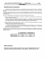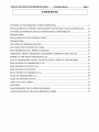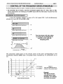
1
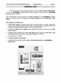
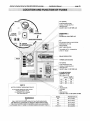
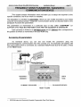
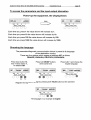
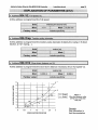
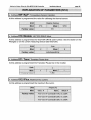
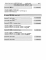
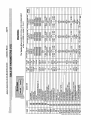
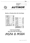
AUTINOR
User Manual
Programme « ARB. V07 ))
Version of 31 october 2002
Autinor's Vector Drive for Otis MCS 220 M Controller
Installation Manual
page 2
Autinor's Vector Drive for Otis MCS 220 M Controller
Installation Manual
page 3
WARNING
This manual is deemed correct on going to press.
The information contained has been scrupulously checked. However AUTINOR declines al1
responsibility for error or omission.
Should you notice any discrepancy or unclear description, or if you have any suggestions, we
would appreciate your written comments (by mail fax or Email) to:
Société AUTINOR - Service Documentation
Z.A. Les Marlières
59710 AVELIN
n [33103-20-62-56-00
B [33] 03-20-62-56-41
[email protected]
This manual is the property of AUTINOR, from whom it may be bought (at the above address).
It may however by freely copied in order to communicate information to those who might need it.
We can only authorise a complete copy, without neither addition nor removal of
information
Where quotations are taken, the following at least must be noted:
-
The Company name of AUTINOR,
-
The date of the original edition.
ELECTROMAGNETIC COMPATlBlLlTY
Since the 1st January 1996 al1 lift installations are obliged to respect the essential requirements
of the European Directive 891336lCEE concerning Electromagnetic Compatibility (EMC).
The equipment is only one component of an installation; it is therefore not obliged to show the
< < marking as stated in this directive. However in order to allow you to write your declaration
of conformitv, and according to professional rules, al1 AUTINOR Drive are supplied with an
engagement of conformity.
Your declaration of conformity can rest on this engagement,
only if the equipment has been installed exactly as advised in this manual.
O Copyright 2002 AUTINOR All rights reserved.
Autinor's Vector Drive for Otis MCS 220 M Controller
Installation Manual
page 4
Autinor's Vector Drive for Otis MCS 220 M Controller
Installation Manual
page 5
PREAMBLE
Handling advice for equipment:
Whatever the load, handling operations can be dangerous (collision, dropping, crushing, ...). Whenever
possible use mechanical handling rather than manual handling. When manual handling can not be avoided, respect
the rules.
At European level, these rules are set out in the Directive 90/269/CEE, Council Directive dated 19 May 1990
"concerning minimal heath and safety instructions for manual load handling with risks, to the worker, notably in the
lower spinal area".
En France, la réglementation de la manutention manuelle est constituée des textes suivants :
Code du travail article R 231-72 (Décret no 92-958 du 3 septembre 1992 transposant en droit français la
directive européenne 92/269/CEE)
« Lorsque le recours à la manutention manuelle est inévitable ... un travailleur ne peut être admis à porter
d'une façon habituelle des charges supérieures à 55 kilogrammes qu'à condition d'y avoir été reconnu apte
par le médecin du travail, sans que ces charges puissent être supérieures à 105 kilogrammes. ))
Décret no 95-826 du 30 Juin 1995, Titre le' - article 8 « fixant les prescriptions particulières de sécurité
applicables aux travaux effectués sur les ascenseurs ))
+ Circulaire de mise en œuvre DRT 96/3 du 25 Mars 1996
« ... Les travaux comportant le port manuel d'une masse supérieure à 30 kilogrammes, ou comportant la pose
ou la dépose manuelle d'éléments d'appareils d'une masse supérieure à 50 kilogrammes, ... doivent être
effectués par au moins deux travailleurs ;))
complétée par la norme française N F X 35-109 qui donne des recommandations plus précises qui prennent en
compte les paramètres suivants :âge du travailleur, nature de la tâche (occasionnelle ou répétitive), charge unitaire,
distance parcourue :
Load permitted
(occasional carrying)
Load permitted
(constant carrying)
Man 18 1 45 years
30 kg
25 kg
Man 45 160 years
25 kg
20 kg
Safety measures:
Follow the instructions which were given to you by your management when using
individual protection equipment (gloves, shoes, glasses, restraint harness, etc).
Autinor's Vector Drive for Otis MCS 220 M Controller
Installation Manual
page 6
Autinor's Vector Drive for Otis MCS 220 M Controller
Installation Manual
page 7
CONTENTS
CONTROL OF THE FREQUENCY DRIVE (PRINCIPLE) ................................................................
9
INSTALLATION OF A UTINOR 'S VECTOR DRIVE FOR OTIS MCS 220 M CONTROLLER........13
CONTROLLER POSITION AND ELECTROMAGNETIC COMPATIBILITY ...........................14
15
GENERALITIES.................................................................................................................................
INSTALLATION OF THE CONTROL PANEL ..................................................................................
16
CONNECTIONS ................................................................................................................................
17
18
LOCATION OF TERMINAL BLOCKS ..............................................................................................
19
LOCATIONAND FUNCTION OF FUSES .......................................................................................
ELECTROMECHANICAL WIRING DIA GRAMS .............................................................................
20
FREQ UENCY DRIVE PARAMETER /DIAGNOSTIC COMMULVICATION DE VICE ....................21
26
PO WER-UP FOR INITIAL MOVEMENT (1/2)...........................................................................
LIST OF PARAMETERS. INPUTS. OUTPUTS. FA ULT CODES. IN VECTOR DRIVE ..................29
31
EXPLANATION OF PARAMETERS (1/12).......................................................................................
EXPLANA TION OF INPUTS (1/2)................................................................................................
43
EXPLANA TION OF OUTPUTS.........................................................................................................
45
EXPLANATION OF VARIABLES (1/3) .............................................................................................
46
TABLE OF PARAMETERS (1/2) .......................................................................................................
49
51
TABLE OF INPUTS/OUTPUTS ........................................................................................................
TABLE OF FAULT CODES ...........................................................................................................
52
APPENDIX .........................................................................................................................................
54
L OAD WEIGHING VEC l 5 INTERFA CE BOARD............................................................................
56
57
CONFIGURATION OF THE L OAD WEIGHINGL WDEE ..............................................................
Autinor's Vector Drive for Otis MCS 220 M Controller
Installation Manual
page 8
Autinor's Vector Drive for Otis MCS 220 M Controller
Installation Manual
page 9
CONTROL OF THE FREQUENCY DRIVE (PRINCIPLE)
For the Frequency Drive to work, it needs as well as a full safety lane, to receive:
the direction Up or Down, and the movement speed (V2, VI, Vins, Viso or VO).
These informations are making by the OTOI board with the information receive from the
lift controller.
1MOVEMENT IN V2 (Full speed):
If the lift controller decides to move off in full speed V2, it will simultaneously
activate the Inputs V2, VO and MO or DE.
f
The slow-down will take place
by losing V2 but keeping VO
and MO or DE until the
stopping point.
SLOW DOWN POINT*
~STOPPING
POINT-
/
The slow-down signal (loss of V2) should come at the point corresponding to the
deceleration distance (DV2) read in the graph below increased by 10 centimetres run in
vo .
Figure 1
Slow down distance DV2 in
relation to the nominal speed
O
O
0.5
1
1.5
2
SPEED IN M ETRES PER SECOND
2.5
3
Remark:
This figure shows
average slow down
distance. For setting,
see field document.
Autinor's Vector Drive for Otis MCS 220 M Controller
Installation Manual
page I O
1 MOVEMENT IN VI:
* If the controller decides to move off in VI speed, it will simultaneously activate the
Inputs VI, VO and MO or DE.
f
1
MO or DE
O
-
b
SIGNAL COMING FROM THE CONTROLLER
The slow-down will take place
by losing V I but keeping VO
and MO or DE until the
stopping point.
mls
f
VOtVItMOorDE
SLOW DOWN POINT
STOPPING
POINT
Note:
When on Inspection, you will
lose VI and VO to stop on the
brake.
~
* If the Lift controller decides to move off in VO, it will simultaneously activate the
inputs VO and MO or DE.
f
,~ ~,~,
mls
A
VO
Io M rO ~, 1~
DE
1
, ,
VO + MO or DE
-
n
....
I
STOPPING
POINT
,
;
FT
VO will disappear
stopping point.
at
the
The movement inputs VO, VI, V2, UP (MO) and DOWN (DE) use opto-electronic
coupiers which can receive AC or DC signais from 24 to 220 V.
Autinor's Vector Drive for Otis MCS 220 M Controller
Installation Manual
page II
DESCRIPTION OF THE SEQUENCE OF SIGNALS FROM START-UP
AT FULL SPEED V2 UNTlL STOPPING.
A
V2 = high speed
Slow-down
Acceleration
VO = Set-up Speed
and re-levelling
O
O
O
F
@
1. When the controller has decided that it can use full speed V2, it will activate V2, VO and
give the direction Up (Mo) or Down (De). The Frequency Drive having received the
order to move, energises the L contactor, then when the capacitor voltage is sufficient,
the S contactor. L and S stabilise electrically the motor, then the FR contactor supplies
the brake for opening.
2. We start by applying low voltage and the lift accelerates. The acceleration will last the
time programmed at parameter « Acce » (Acceleration).
3. The lift has reached the speed corresponding to the value programmed at « V2 » (Full
speed).
4. The slow-down signal is given, the V2 signal disappears but VO stays along with MO or
DE. The car slows down according to the distance programmed at parameter « DV2 ))
(Slow-down distance in V2) to reach VO.
5. VO is reached, the signal is given, the VO and MO or DE are kept until the stopping
point.
6. The stopping point is reached, VO disappears but keeping the direction MO and DE and
the transition from VO to zero speed start.
7. When zero speed is reach, the Vector Drive electrically stabilises the rotor for the time
programmed at parameter « FrArr » (Brake time on stopping).
8. The Vector Drive drops the brake by deactivating the brake contactor FR. An L or S
contact (STOPR) informs the controller that the movement is finished so that the MO or
DE direction signal can be deactivated and the doors opened.
NOTE:
Stages ( 5 ), ( 6 ), ( 7 ) and ( 8 ) have been voluntarily exaggerated in order to clarify
the drawing.
Autinor's Vector Drive for Otis MCS 220 M Controller
Installation Manual
page 12
Autinor's Vector Drive for Otis MCS 220 M Controller
Installation Manual
INSTALLATION
OF
A UTINOR'S VECTOR DRNE
FOR
OTIS MCS 220 M CONZROLLER
page 13
Autinor's Vector Drive for Otis MCS 220 M Controller
Installation Manual
page 14
CONTROLLER POSITION
AND ELECTROMAGNETIC COMPATIBILITY
When the machine room supports or is near a radio or television reception
aerial, do not put the controller cabinet in the aerial receiving zone (figure 1).
BAD !
Aerial
GOOD !
Fce
Aerial
ption
Placing the frequency drive outside the aerial receiving zone
If you can not find a suitable place for the frequency drive cabinet, çiet the aerial
moved! If that is not possible, contact AUTINOR who will decide along with the building
owner, what measures need to be taken according to the EN 12015 and EN 12016
Standard for lifis, escalators and passengers conveyors.
Use of differential circuit breakers with Autinor's Frequencv Drives
First of al1 as a reminder:
The low voltage directive explicitly states that electrical lift installations are excluded 'from its field of
application and so the standards relating to electrical installations only applies as far as the input
terminals of the main lift installation switch (cf EN 81 3 13.1.1.2) ;
Nevertheless the safety of al1 people must be ensured, and so to do this, we rely as much as possible
on the detail of C 15-100 taking into account the imperatives concerning lifts.
The standard C 15-100 § 532.2.1.3 states that:
« Les dispositifs de protection a courant différentiel-résiduel doivent être choisis et les circuits électriques
divisés de telle manière que tout courant de fuite à la terre susceptible de circuler durant le
fonctionnement normal des appareils ne puisse provoquer la coupure intempestive du dispositif. ))
AUTINOR frequency drives have a normal current leakage when loaded around 100 mA. We therefor
recommend the Lift installation be supplied through a differential circuit breaker with a differential current (=
« sensitivity ») 16, = 300 mA.
What is more, C 15-100 states that for electrical installations cabled conform to the TT diagrams
(installations powered by the public electricity network), people should be protected against indirect contacts
by differential residual current circuit breaker which implies the following of the relation ship which links the
circuit breaker differential current 16, to the maximum conventional voltage of the UL contact and of the
earthing socket resistance:
16, * RAI UL(NF C 15-100 § 532.2.4.2)
If the earthing socket resistance exceeds 100 R, the electrician may use an S type differential circuit
breaker with a differential current of 300 mA, which will ensure protection against indirect contact for an
earthing socket resistance of up to 167 R. You should nevertheless ensure that a « full load )) movement
does not break the circuit at the wrong moment.
Autinor's Vector Drive for Otis MCS 220 M Controller
page 15
Installation Manual
GENERALITIES
The main function of the complete product is, from an OTlS controller MCS 220 Ml
to drive an AUTINOR 's Vector Drive (PWM principle), itself driving an AUTINOR
gearless motor ("
The communication protocol between the OTlS controller and the AUTINOR 's Vector
drive is the same as the one between the OTlS controller and the OTlS drive called
OVF20.
This product is composed of:
a W F drive adapted to geared motor, with Vlf speed control or Vector control (the
model of drive depends on the rated power) and to asynchronous gearless motor, with
a software especially adapted based on vector control principle,
a transformer 440 VA (with a BG22 board), destined to supply the brake and the OTOI
interface board,
a P318 module supplying the brake (180 VDC during opening and 60 VDC during
maintaining phase): this module is especially adapted to "
II
3 contactors: S, L and FR,
a 3 phase network current filter,
an OTOI interface board between OTlS controller MCS 220 M and AUTINOR 's
Vector Drive.
Autinor's Vector Drive for Otis MCS 220 M Controller
Installation Manual
page 16
INSTALLATION OF THE CONTROL PANEL
Cabinets dimensions:
Models 2,3,4,5,6: L = 562 mm, H = 680 mm, P = 285 mm, Weight = app 40 Kg
Models 7,8 and 9: L = 800 mm, H = 1200 mm, P = 400 mm, Weight = app 70 Kg
Resistors cabinet: L = 600 mm, H = 320 mm, P = 250 mm, Weight = to ?? Kg
NB:
For the purpose of delivety, the support bar is fixed to the studs for fixing the cabinet.
Entty for wiring and trunking is at the bottom.
Don't forget than the EN-81-1 Standard 5 6.3.2.1 :
6.3.2.1
The dimensions of machine rooms shall be sufficient to permit easy and safe working on
equipment, especially the electrical equipment.
In particular there shall be provided at least a clear height of 2 m at working areas, and:
a) a clear horizontal area in front of the control panels and the cabinets. This area is defined as follows:
1) depth, measured from the external surface of the enclosures, at least 0,70 m;
2) width, the greater of the following values: 0,50 m or the full width of the cabinet or panel;
b) a clear horizontal area of at least 0,50 m x 0,60 m for maintenance and inspection of moving parts at
points where this is necessary and, if need be, manual emergency operation (12.5.1).
Autinor's Vector Drive for Otis MCS 220 M Con,troller
page 17
Installation Manual
CONNECTIONS
,
1
INCREMENTAL ENCODER
1
STEGMAN
HENGSTLER
OTHERS
Conventional connection
'
Terminal box _
,
,
~t."na'i"l
Screening flat cable
link,e,d,kn,~,erl~hp,~m~n,";ay
,,.,.
,...........
.......
..
.
.
.
....
.
.
.
.
.
.
.
.
.
.
.
...
9
L.J,.M
, .... (3 51
'A Phase cables
The cables should only be separated 'from
the screening once inside the terminal box.
K622
Screened cable,
&
Keep the motor cable as far apart from the power cable
as possible, inside as well as outside the controller.
Concerning the Frequency Drive
In order to reduce dlsturbances
a screened cable (LIWCY type,
mlnlmal length of cable: 311150)
rnust be used.
To be completely efiicient the screenlng
must be connected at the same time
to the controller rnetal casing
and to the motor metal housing.
Autinor's Vector Drive for Otis MCS 220 M Controller
Installation Manual
LOCATION OF TERMINAL BLOCKS
Towards power supply
transformer
ov
18V
Electromechanical Terminal Rail
page 18
Autinor's Vector Drive for Otis MCS 220 M Controller
Installation Manual
page 19
LOCATION AND FUNCTION OF FUSES
FU1 (VECOI)
ELECTRONIQUE AND
SIGNAL POWER SUPPLY
PROTECTION
2A-250 V dim: 5 X 20 TlME LAG
SPARE FUSE
for FU7
2A-250V dim: 5x20 TIME LAG
FU+
DC PROTECTION BY PROTISTOR
DEPENDING ON THE
DRIVE MODEL.
(SEETABLEBELOW)
The position of FU+ is depending
of the V.F. Model
BRAKE CONTACTOR
POWER CONTACTORS
FU1 (OTOI)
ELECTRONIQUE AND
SIGNAL POWER SUPPLY
PROTECTION
2A-250 V dim: 5 X 20 TlME LAG
3 PHASE NETWORK
CURRENT FILTER
380 V dim: 6 X 32
L3P
If you should replace the rnotor current
rneasuring device VECl2
It is IMPERATIVE to followed
the same path wire
ONLY USE PROTISTORS CAPABLE OF WHITHSTANDING 600V
AND SPECIALLY CONCEIVED TO PROTECT SEMI-CONDUCTORS.
THE USE OF OTHER FUSES IS DANGEROUS AND COULD DAMAGE
THE TRANSISTORS IF THERE IS A POWER SURGE OR SHORT CIRCUIT.
2A
FuVe
TRANSISTOR
COOLING
FAN
PROTECTION
0,5A-250 V dim: 5 X 20 QUlCK AC TING
MOTOR CURRENT MEASURING DEVICE
WARNING!!!
2A
MODEL
NO2
PROTISTOR
25 A (10x38)
NO3
40 A (14x51)
N"4
50 A (14x51)
NO5
N06/ NO7
63 A (22x58)
80 A (22x58)
@