1
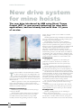
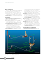
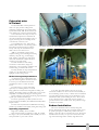
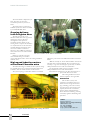
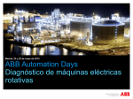
IN THIS ISSUE
4
Drive system for mine hoists
A new ABB drive using Direct Torque Technology has
been used successfully for various mine hoist
applications over the last 1.5 years. This new
generation of drives offer unequalled speed and
torque control performance, as well as low impact on
the supply network.
in
12 Simplicity
controls
A recent US survey
clearly indicated the
four most desired
features of an AC
drive. Simple control
and setup came out
tops, while convenient operator
interface, programmability and pricing were also important.
14
9
Eliminating harmonic
distortion
The latest regenerative
four-quadrant ABB
drive offers huge cost
savings in industrial
power supplies. The
physically small drive –
up to 80% smaller than
alternative units – uses a
combination of
patented technologies to
remove the need for
expensive multi-pulse
diode rectifiers.
Mill starting
ABB has taken the guesswork out of mill starting
with the design of a tool that can calculate all the
relevant parameters for a range of mill applications
which use wound rotor induction motors with liquid
resistance starters.
We have a winner!
In the previous issue of ABB Technology Solutions
we invited our readers to enter a lucky draw.
Congratulations to Margie Kotze from GFJ who is
the lucky recipient of a LAMY Logo fountain pen.
The pen is kindly sponsored by W Vos & Company
(Pty) Ltd, distributor of LAMY Writing Instruments.
Tel: +27 11 493-7193
TECHNOLOGY SOLUTIONS
is published by ABB South Africa.
Address:
ABB Park, 3 Eglin Road, Sunninghill
Postal:
Pvt Bag X37, Sunninghill, 2157
www.abb.com/za
Telephone:
+27 11 236-7000
Facsimile:
+27 11 236-7001
Managing Editor:
Chesney Bradshaw
[email protected]
Editorial Panel
Richard Becker
[email protected]
Andrew Williamson
[email protected]
Shivani Chetram
[email protected]
Ntaga Mojapelo
[email protected]
Willie Zeelie
[email protected]
Jacqueline Burn
[email protected]
This publication was designed,
compiled and produced on
behalf of ABB South Africa by
M&M Publications (Pty) Ltd.
PO Box 1644, Saxonwold 2132
Johannesburg, South Africa.
Tel: +27 11 880-5790
Fax: +27 11 880-5789
E-mail: [email protected]
Whilst the compilation and production of ABB Technology Solutions is done with great care and attention and every effort is made to prevent mistakes, neither
ABB in Southern Africa nor its principles or subsidiaries, nor M&M Publications (Pty) Ltd. accept responsibility for any errors or the consequences thereof.
2
APRIL 2003
NEWS BRIEFS & EDITORIAL
new developments
Sappi chooses IT Direct Drive
ABB has received an order to supply an Industrial IT Direct Drive system for
Sappi Kraft’s number four paper machine at its Tugela Mill in Kwazulu-Natal. The
system represents new direct drive technology, which is becoming the industry
standard in drive systems.
The contract, valued at nearly R26 million, includes the delivery of 24 drive
sections, 17 permanent magnet motors and seven standard asynchronous motors
without gearboxes, as well as application software and all related services such as
cabling, installation, commissioning and training.
“ABB’s Direct Drive will enable Sappi to reduce the total life-cycle costs of
operating the paper machine,” says Urs Leuenberger, Technical Director, Automation Technologies division, ABB South Africa. “The unique solution reduces
mechanical components in the paper machine drive, thereby simplifying it and giving
it improved running efficiency and cost of ownership.”
The solution is based on the new permanent magnet motors, frequency converters and application software. The drive system uses direct drive philosophy, which
encompasses the use of permanent magnet motor technology to provide good
torque at low speeds to eliminate the need for gearboxes. The start-up of the paper
machine is scheduled for August 2003.
Bringing new technology to customers
ABB recently took a giant leap in bringing new technology to its customers by
hosting its customer open days in Richards Bay and Durban for the first time.
The event, aimed at keeping customers informed about new products and
technology within ABB, was well staffed with ABB’s technical and marketing
personnel.
The open days were of interest to all industries – utilities, process industries,
manufacturing and consumer industries and oil, gas and petrochemical fields.
Products from various divisions were exhibited and guests were given the opportunity to attend on-going presentations and hands-on demonstrations.
The exhibition, attended by over 200 customers, included the launch of ABB’s
new ACS 800 Low Voltage Drive family.
ABB increases presence in PE
ABB has consolidated and expanded its representation to customers in the Port
Elizabeth area and positioned itself to support the growing automotive industry and
other industrial initiatives such as Coega.
The company recently relocated its automotive, robotics, and low voltage and
medium voltage products businesses to the new office at Newton Park, bringing
them together to provide a complete offering to customers.
“Our stronger presence in this area will allow us to focus better on our customer’s needs in the growing automotive industry and provide them with improved
access to international power and automation technologies,” says Per Wanland,
senior vice president at ABB South Africa.
ABB ranks high in reputation stakes
ABB was recently ranked highly in the “World’s most respected companies”
report, run by the Financial Times and PriceWaterhouse Coopers. The study
comprised interviews with 1000 senior executives and opinion formers in 20
countries.
In the engineering sector ABB was placed third (Toyota was first and General
Motors second), one place down from the second spot in 2001. Of all the global
companies listed, ABB was ranked in the top 50 as one of the world’s most respected
companies. The group’s position was No. 33, well ahead of its competitors.
In the business leader category, ABB’s president and CEO, Jürgen Dormann, was
ranked in the top 50. ABB also featured strongly in the categories of companies
making the most impact on economic and social issues in emerging markets and
companies that best manage environmental resources.
Committed
to innovation
O
ver the years, ABB South
Africa has used its knowledge and expertise to
achieve excellence in power and
automation technologies.
Through innovative solutions, we
have remained committed to providing our customers with superior and
competitive products and services.
To this end we continue to invest
in our eight factories located throughout South Africa by installing new
technology and production systems.
Social responsibility
On the Corporate Social Responsibility side, ABB has shown its
commitment to South Africa in a
number of different ways.
We have invested in several
sustainable projects nationwide in
order to empower local communities.
We are a black economic empowerment company, with 20% of our
local holding company being owned
by WIPHOLD, a financial services
company run and owned by black
women.
“
ABB South Africa is
committed to providing its
customers with superior
and competitive
products and services.
”
Through these efforts, we at ABB
strive to put our customer first,
bringing them the best technology and
service in order to help them prosper
in their business ventures.
Carlos
Poñe
President
and CEO
ABB South
Africa.
APRIL 2003
3
DRIVE TECHNOLOGY
New drive system
for mine hoists
The new drive introduced by ABB using Direct Torque
Control (DCT) is now proven technology for mine hoist
applications, and has already had more than 1.5 years
of service.
starters. This type of drive was not suitable for automatic
hoisting systems.
Introducing DC-technology with Ward-Leonard technology
was a big step in drive technology, providing excellent speed
and torque control of the hoist motor.
The introduction of thyristor convertor technology
exposed the drawbacks of the WL system. The space saving
thyristor convertor replaced the DC generator as well as its
driving AC motor. The capital expenditure was reduced and the
operating efficiency largely improved when the thyristor
technology was introduced in the mid 1960s. The main
drawbacks of thyristor convertor technology, reactive power
and harmonics generation, were dealt with by the installation
of tuned filters. The voltage fluctuations in installations with
weak power supply could only be solved by installing expensive
rotating synchronous condensor or a static VAR unit, SVC.
Looking back
The headframe of the Pyhasalmi Mine in Finland.
T
he first installation in the Pyhasalmi mine in Finland
uses MV technology with an ACS 6000 SD drive and
synchronous motor. ABB has also installed two hoists
in the Kemi mine in Finland with LV technology and induction
motors for two hoists using the ACS 600 drive with high speed
induction motors.
ABB’s new generation of drives offer unequalled speed and
torque control performance, as well as low impact on the
supply network by controlling the power factor to unity with a
minimum of harmonics distortion.
Changes in technology
Drive technology for mine hoists has seen many changes
over the past decades.
The first electric solution widely used was the induction
motor with resistor banks in the rotor circuit. It provided
controlled acceleration and retardation by using variable
secondary resistance using switching contractors or liquid
4
APRIL 2003
For the sake of completeness of this summary, the
predecessor or thyristor, the mercury arc rectifier, was
successfully introduced earlier but never captured major
market share.
Thyristor technology then dominated the market for
almost two decades until cyclo-convertor technology was
introduced.The main driving factor for the development of
the cyclo-convertor was the increased cost of DC machines.
The demand for DC machines has been drastically reduced
with the abandoning of the WL system, eliminating the need
for the DC generator. The largest market of DC machines,
rolling mill applications, required fewer new large motors as
the number of new mills decreased, and thinner metal could
be produced by modern continuous casting methods.
For a few years during the mid 1980s the cyclo-convertor
and the synchronous motor captured the market for large
mine hoists.
Smaller hoists were still using DC-drives. The combination of high speed DC motors and gearbox gives the lowest
capital expenditure for power trains up to about 1500 kW.
Paradigm shift
However, a paradigm shift to new AC technology is
underway, also for this power range.
Cyclo-convertor technology became a financially competitive alternative to the DC solution. However, the negative
influence on the network side was more severe than caused by
DRIVE TECHNOLOGY
Control of ACS 6000 SD
The difference between a conventional Pulse Width Modulation (PWM) drive and the Direct Torque Control (DTC)
of ACS 6000 is illustrated in the figures below. The control is made in the Control Unit (COU).
Flux vector control
DTC-control
ARU
ISU
V
Speed
control
Torque
control
Speed
control
Modulator
Torque
control
f
INU
M
PG
M
PG
3
3
The PWM has a modulator module that determines the pulse pattern. This computation is very time consuming and
slows down the motor control. The DTC drive control has eliminated the modulator. Instead, the torque controller
acts directly on the gate control unit. As the program allows the gate control circuit to be updated 40 000 times
every second, extremely fast torque control is achieved.
DC. Because the cyclo-convertor produces more complex
harmonics than the corresponding DC drive it became more
costly to meet the requirements of the power utilities. Add to
these new demanding requirements on power quality, the
drawbacks of both DC and cyclo-convertor drives became
major issues. Reactive power is today not a free issue but a real
operating cost parameter.
Equally important cost issues are total harmonic distortion
(THD), flicker and telephone interference factor (TIF).
Even elaborate and expensive fixed filters will not satisfy
power quality requirements in normal mine environment.
Today, not only are the requirements of the power utilities
stringent, but the internal consumers of electricity in the mines
are demanding. Computers and instrumentation, as well as
human resources make the mine spend large amounts on
improved power quality.
Voltage drops and voltage variations caused by obsolete
technology requires expensive voltage support systems.
There is also strong demand for improved performance of
the power train such as speed and torque control in particular
in rolling mill applications to enable higher quality of finished
steel products.
To satisfy the requirements for higher drive performance
and higher network quality, ABB has developed a new generation of drives. Two basic product series are available, ACS600
for LV and ASC6000 for MV systems.
Main components of ACS6000 SD
The main components of the ACS 6000 SD drive starting
at the motor side are: INU, EXU, ARU, IFU, CBU including
CHU and CLU, COU, WCU.
Details: INU, Invertor Unit controls the motor torque
and speed in coordination with the EXU, Exciter unit. The
power factor of the motor is controlled to unity. The power
circuit includes three identical phase modules with IGCT
(Intergrated Gate Controlled Thyristor) and diode power
semiconductors.
The INU generates a motor frequency that for a mine
hoist is typically about 10 Hz, or lower at full hoisting speed.
EXU, Exciter Unit powers the motor excitation. The
convertor is a six-pulse thyristor bridge.
ARU, Active Rectifier Unit, supplies power to the CBU
unit or in generation mode feeds power from the CBU back to
the network. By smart control, the power factor is controlled
to unity and the harmonic distortion is minimized.
The three phase modules are identical to the INU phase
modules. IFU, Internal Filter Unit is needed in some networks
to keep the harmonic distortion within the limits specified by
IEEE- 519 or IEC 61000-2-4, cl.2
CBU, Capacitor Bank Unit absorbs the ripple currents
generated by the ARU and INU units. At start-up of the
drive, the capacitor bank needs to be charged before activating the ARU and INU units. This is done by the CHU,
Charging Unit using auxiliary power.
VLU, Voltage Limiting Unit protects the DC-link against
overvoltage.
The DC-link has a neutral, a positive and a negative bus
providing three-level control of the drive. This means that
switching is made from positive to neutral and from neutral to
negative and reverse. This increased the speed of the control
and reduces the voltage rise dv/dt.
APRIL 2003
5
DRIVE TECHNOLOGY
Water cooling unit
The drive is water cooled. The drive has an internal cooling
loop with deionized water. In environments where the
temperature might be below freezing point, anti-freeze glycol
can be added at the expense of a slight derating of the drive.
A heat exchanger is provided. The external cooling circuit
can be either plant water or an external water loop with water
to air heat exchanger.
Advantages
The main advantages of the ACS 6000 SD drive with
synchronous motor compared to a cyclo-convertor drive using a
synchronous motor or induction motor are:
z Power factor control: Both the motor and the drive are
normally operating at power factor =1. This is the most
efficient mode of operation, reducing both losses in the
hoisting system and the supply network.
z Low voltage drops: Because the power factor is unity, the
voltage drop caused on the supply network is reduced to
about 20 % of the voltage drop caused by a cycloconvertor or DC-drive. This also means that the new
technology allows weaker network meaning less investments in power lines.
z Less transformer power required: Since no reactive
Flow diagram of the underground operation.
6
APRIL 2003
power is required, the throughput power in the transformers is substantially less than in a cyclo-convertor drive.
Typically, the installed transformer power is 50% of what is
required for a cyclo. Also, only a single transformer is
required.
z Low levels of harmonics: The DTC convertor produces
low levels of harmonics. Basically, all harmonics below the
25th will be eliminated by the pulse pattern control
software. Therefore the normal hoisting installation does
not require harmonic filtering to comply with for example
IEEE 519 requirements.
z Fuse-less design: No fuses or DC-breakers are required in
the power circuit. The fast action of the IGCT power
semiconductor protects the system against damages at
faults.
z High efficiency:The synchronous motor has higher
efficiency than corresponding DC – or induction motor.
Adding to this, lower losses due to less transformer power,
fuse-less design and elimination of filters for power factor
correction and harmonic suppression, the new technology
offers the best total efficiency.
Installed base and experiences
The mine hoist systems are currently in operation and a
third system delivered and under site erection.
DRIVE TECHNOLOGY
Pyhasalmi mine
in Finland
The Pyhasalmi Mine started operation in
1962 as an open pit mine. Underground
production commenced in 1975 using hoisting
systems delivered by ABB. The known reserves
were sufficient for operation until about 2001.
In the mid 1990s a new deep ore body was
found. Further exploration revealed that the
ore body contained about 20 million tonnes of
copper, zinc and pyrite ore extending the life
of the mine by at least ten years.
It was decided that a new 1450 m deep
shaft should be sunk for a new hoisting system.
This makes it the deepest mine in northern
Europe. The ramp was extended from the
1000 m level to the 1450 m level.
ABB was awarded the contract for the
complete hoisting system including the hoisting
machinery, skip with cage, counterweight,
head-, balance- and guide ropes with attachments. This includes the complete electrical
system for power and control.
The time schedule for shaft sinking,
construction of head frame, design and
manufacture of the equipment, installation and
commissioning was less than 24 months.
The time schedule was kept and production
started on 1st July 2001. Below are some
highlights of the hoisting system.
The hoist room at the Pyhasalmi Mine.
Basic hoist system parameters
A configuration using combined skip with
cage and counterweight was selected. The hoist
is a four-rope 4.5 m diameter friction hoist
with deflection sheave to match the shaft
Water cooled
layout.
The payload is 21, 5 tonnes and hoisting
speed 15,5 m/s. Hoisting distance is 1407 m.
Rope guides were selected with fixed guides at loading and
dumping. The loading station is provided with a conveyor belt
suspended on load cells eliminating the measuring flask.
On-line continuous rope tension monitoring is provided in all
6 guide ropes and the four head ropes.
The hoist is powered by a 2,5 MW synchronous motor
torque and speed controlled by ACS 6000 SD with DTC, Direct
Torque Control.
The host control system based on ABB Advant technology
provides rope oscillation control, ROC, during the hoisting cycle.
Operating experience
High total availability, 99.7% recorded.
More than 20 months of production to date, has verified
the design of the system. Reliability and availability tests have
been performed as a part of the contract.
4 200 kW synchronous motor at the St. Gotthard tunnel.
A test with 12 months duration that was part of the
contractual conditions has shown that the total availability of
the total hoisting system was 99,7 % which must be considered
very high. During this time, there were no disturbances at all
related to the drive system including the motor. The six hours
or 0.3 % down time was a single fault occasion caused by a
ground fault in the hoist control system. The production target
for 2002 was exceeded.
Sedrun Installation
The new St. Gotthard tunnel is currently being built
between Switzerland and Italy. The total length will be 57 km.
To speed up the project, an 800 m deep shaft is sunk about
halfway so that the work can proceed from 4 faces. The shaft is
furnished with two hoists, a 4 rope 4.8 m friction hoist with
cage and counterweight and an auxiliary single drum hoist.
APRIL 2003
7
DRIVE TECHNOLOGY
The tunnel will be completed in year
2011. The hoist was taken into
commercial operation by the end of
2002.
The friction hoist is powered by a
4200 kW synchronous motor controlled
by ACS 6000 SD DTC drive.
Ongoing deliveryInco-Creighton mine
The DC motor of the 5.5 m
diameter double drum main cage hoist is
reaching the end of its life. Inco
investigated several options for
continued operation. Repair of the
existing motor to improve the insulation
was rejected because of the down time
required. Different alternatives with a
new motor and drive resulted in a
decision to select ABB’s new technology
with synchronous motor and ACS 600
SD drive.
The hoist chamber at the Sedrun installation.
Delivery is currently in progress
with scheduled change over time in
August 2003. Picture below shows the existing installation
SD but the power circuit uses IGBT semiconductors instead of
with DC motor.
IGCTs.
ABB has currently two hoists under installation in the Kemi
High speed induction motors
Chromite mine in northern Finland. The 3.2 m friction hoist
at the Kemi Chromite mine
with skip + cage and counterweight is powered by a 1500 kW
1000 rpm induction motor with an ACS 600 drive.
The DTC technology is available for 690 V systems voltage.
The single drum auxiliary hoist is powered by a 75 kW
It is available in sizes up to 4730 kVA. The drive ACS 600 is
1000 rpm induction motor with ACS 600 drive.
available in both air cooled and water cooled versions.
The mine had a preference for AC drive since there are no
The system topology of ACS 600 is similar to ACS 6000
previous DC drives in the mine.
The hoisting installation is scheduled for completion in August 2003.
Conclusion
The new drive system, with
synchronous or induction motors for
mine hoists has brought about advantages, including power factor control,
low voltage drops, less transfer power
required, lower levels of harmonics,
fuse-less design and high efficiency.
These advances in technology are being
successfully applied to demanding mine
operations.
Author
The Inco Creighton double drum hoist with existing DC motor.
8
APRIL 2003
Börje R Johansson
Manager, Sales of Underground Mining
ABB Industries AB
Tel. +46 -21-340335
Fax: +46-21-185890
[email protected]
SIMULATION TOOL
Simulation tool
for SAG mill starting
When a local platinum mine experienced dropped-charge
problems a number of experts were consulted to prevent
any possible damage to the mill. Now ABB has come up
with the perfect solution: a tool that calculates all the
relevant parameters for a wide range of mill applications.
E
ngineers using typical grinding mill applications which
involve a wound rotor induction motor (WRIM),
gearbox, and liquid resistance starter will know that
predicting the speed (and other parameters) during the start is
very much a black art, or at very least a case of being forced to
use what was used before.
A WRIM has the advantage of being able to supply a large
range of starting torque by adding external resistance to its
rotor circuit. A further benefit is that the motor can supply high
torque levels at very much lower currents than an equivalent
squirrel-cage induction motor (except if it is driven by a
variable speed drive). A typical mill will require a peak torque
of approximately 130% of rated torque to start, and since
most mining sites have limited supply fault levels, a WRIM is
ideal for this application.
The basic principle of the start is to vary the external
resistance in the WRIM rotor circuit by using a liquid resistance
starter (or other resistance devices in some applications). A high
resistance causes a low torque and a correspondingly low current,
while a low resistance causes a high torque and a correspondingly
high current.
A good rule-of-thumb guide is that there is a one-to-one
ratio between current and torque: 100% starting torque requires
approximately 100% starting current (compare this with a typical
squirrel-cage induction motor which would require approximately 650% starting current to achieve 100% starting torque).
If the external rotor resistance is held constant, the motor torque
will still vary considerably with speed.
Fig. 2
Fig. 1
Typical simulated mill torque versus angle (rotation)
characteristic; the dip at half a revolution is
exaggerated for the purposes of simulation
conservativeness.
Since the motor speed and the liquid resistance change
continuously during the start, an accurate prediction of the
starting process and its relevant parameters requires a calculation that takes the motor instantaneous torque (and hence
speed), the corresponding load torque and the liquid resistance
value at each time interval during the start. But whose responsibility is it to combine these parameters and predict the starting
process accurately?
In most cases, the mill supplier will be able to provide a
mill torque versus angle characteristic curve, or a mill torque
versus speed curve – assuming constant acceleration. A typical
mill torque versus angle function is illustrated in Figure 1. The
motor supplier is usually limited to being able to supply a set of
characteristic curves of motor torque versus speed – for various
external rotor resistances. The liquid resistance starter supplier
will supply a characteristic in the form of resistance versus time
for various electrolyte concentrations.
Ironically, the mill suppliers or engineers have often
specified a constant accelerating torque for the start, but this
has not been the case.
This had not become an issue until recently when droppedcharge problems began occurring at an ABB customer’s
platinum grinding mill. A dropped-charge occurs when the mill
APRIL 2003
9
SIMULATION TOOL
charge does not break up correctly in the mill, but leaves the
perimeter of the mill (at a high angle) and drops onto the lower
portion of the mill. It is not difficult to imagine what damage a
few hundred tons or more of mill charge can do to the mill
bearings or the mill structure itself.
The problem is new because it appears to be confined to
the newer UG2-reef product, as opposed to the original
Merensky-reef product. The phenomenon can occur in any mill
which is incorrectly operated (loaded) but the possibility is
much greater with a ‘stickier’ product such as UG2 – especially
if the ball to charge ratio is not high enough.
In any event, serious damage was possible to the mill in
question if the dropped-charge problem re-occurred, so a
number of experts were consulted. The result was a suggested
reduction in the initial starting torque by reducing the electrolyte concentration in the liquid resistance starter. When the
revised resistance was implemented, the mill exhibited what
was considered to be very strange behaviour: It slowed down to
such an extent in the first portion of its start that it turned in
reverse for some time, but then proceeded to accelerate
normally to full speed.
Several starts indicated that the revised lower starting
torque was certainly less likely to cause a dropped-charge but
there was understandable concern over the reversing of the mill
during the start. Despite the simultaneous involvement of all
the relevant expertise related to the entire mill installation, it
became obvious that a method of calculation of the starting
10
process did not exist. It was also equally obvious that a method
was required in order to understand and verify what was being
witnessed!
Since the motor was viewed as the most complex component of the installation, ABB AC Machines in Alrode felt that
the rest of the mechanical and electrical system would not be
impossible to mathematically couple to the motor, thereby
allowing a simulation of the entire system. ABB’s original
involvement in the project was as the motor supplier and, since
the motor was designed and manufactured at the ABB Alrode
factory, all the relevant details were readily available.
Significant consultation with the mill suppliers, liquid
resistance starter suppliers and project consulting engineers,
combined with some fairly detailed spreadsheet programming
produced a very useful tool that calculates all the relevant
parameters for a wide range of mill applications which use
wound rotor induction motors with liquid resistance starters.
Typical graphical results from the simulation tool are
presented to show the reversing phenomenon when the liquid
resistance starter’s electrolyte concentration is reduced to a low
level – as witnessed on the plant in question. Figures 2 and 3
show the motor, load and accelerating torque versus time, and
the resulting speed versus time for a fairly high (150 %) starting
torque. Figures 4 and 5 show the same graphs for a lower
starting torque – note the reversing phenomenon in Figure 5
and also the negative accelerating torque in Figure 5.
Figures 6 and 7 show the accelerating torque and speed
Fig. 3
Fig. 4
Fig. 5
Fig. 6
APRIL 2003
SIMULATION TOOL
versus time for a liquid resistance starter set to close its
electrodes in 15 seconds, effectively forcing the system to reach
full speed in this time. Figures 8 and 9 show the same graphs
for the same system but with the liquid resistance starter set to
close its electrodes in 30 seconds, slowing down the start. The
speed versus time characteristic is effectively the same ‘shape’
stretched over a longer time but there is a significant reduction
in the average motor torque and therefore too in its current.
The obvious advantage of this feature is to predict the
maximum current that will be drawn during a start, for
installations where the power system is very weak.
Figures 10 and 11 show the flexibility of the tool beyond
mill loads: An unloaded fan start has been represented by
carefully selected ‘mill’ torque parameters. Note the very
different shapes of the graphs compared with those for a
typical mill load.
Since the simulation tool numerically integrates the relevant
parameters in order to predict the starting process, even
transients can be approximated with careful manipulation of
the variables. Figure 12 shows the transient torques which
occur when the short-circuiting contractor closes at the end of
the starting sequence.
Fig. 7
Author
Robert Melaia
ABB South Africa – Automation Technologies division
Tel: +27 11 617 2000 Fax:+ 27 11 908 2061
Fig. 8
Fig. 9
Fig. 10
Fig. 11
Fig. 12
APRIL 2003
11
DRIVE FEATURES
Providing simplicity
in controls and set-ups
Why is the world demanding drives that are simple to
commission? In a survey of 279 US readers, the trade
magazine Control Engineering asked what features were
most desired in AC drives.
S
ixty-three per cent responded with a request for simple
controls and setups; 45% said they would prefer
convenient operator interface; while 45% mentioned
programmability and 37% were concerned about pricing.
For the past five years, most surveys into what customers
want from their drives invariably show these as the four most
desired features. And, during this period, manufacturers have
been eager to oblige by designing drives, keypads and control
panels that offer some very clever and innovative ways to make
life easier.
Yet, even today – five years on – the surveys still show easy
set-up, ease of commissioning and easy to use as the leading
demands of today’s customers. So are customers disillusioned
with what they are being offered? Are the manufacturers truly
hitting the mark?
User interface
Manufacturers have taken the desire for easy to use drives
to heart and have approached the challenge in three ways.
Firstly, the user interface itself has been closely scrutinised.
Today drive set-ups can be performed quickly using detachable
and/or interchangeable keypad interface modules. Most keypad
modules can be removed, whether the drive is powered or not.
Most companies offer keypads that can be mounted on the
drive, as well as used as handheld devices.
Keypad modules allow users to programme speed, start,
stop, acceleration, deceleration and parameters into the drive.
Some modules permit uploads and downloads so that multiple
drives requiring the same set-up parameters can be programmed
using only one keypad. The parameters for one drive are set
with the keypad. Then those parameters are copied into the
keypad, which is taken to other drives for subsequent setups.
The user then downloads the setup parameters from the keypad
into each drive in succession. These devices normally feature
liquid crystal display (LCD) readouts. The readouts show speed
information, setup parameters, or error codes.
Secondly, manufacturers have been looking at the best way
for the user to interface with the keypad and this has resulted in
an array of push buttons, potentiometers, knobs and digital
scroll dials.
But perhaps the biggest challenge has been improving the
quality of the actual data that is presented to the user and
simplifying the format of what is displayed.
However, the complexity of the data, is dependent on the
type of drive being installed. Micro-drives, or low power
drives, have led the market in terms of simplicity to use. These
12
APRIL 2003
drives really are plug-and-play and invariably need no more than
a start-up routine. As such they are more reliable, easier to use
and easier to understand than their predecessors. The idea is to
keep things simple for the user. With plain language displays
and simple start-up routines, most electricians can operate
them. The real challenge is with drives used for demanding
applications. It is these drives that have complex parameter setups and routines that so often need user-manual intervention.
And it is in this area that manufacturers are now turning their
attentions, driven by three specific customer needs:
• Time saving in installation and commissioning
• Longer uptime
• Reduced scope for errors.
Removing the need for manuals
While keypads have become far more user friendly, the
drives still arrive with very cumbersome manuals and at some
point in the set-up and commissioning, there is a need to refer
to these heavyweight documents. Sometimes, these manuals can
be poorly written and contain highly complex descriptions,
which takes considerable time to decipher, when all the
customer wants to do is switch the drive on.
While most companies today offer alphanumeric displays, in
multiple languages, it is not that user friendly if what is
displayed still needs a manual to decipher the messages. Today,
users want to focus more on their application and less on the
requirements of the drives control algorithm.
A maturing product
Drives are becoming mature products. In the early days,
greater attention was given to getting the power electronics
right and making sure the drive could do what it was basically
intended for – control motor speed and save energy.
As the product matures, then greater emphasis is placed on
giving more functionality but in a more user-friendly way. With
PCs this was through Windows and the mouse. And so it is
with drives and their intelligent keypads and self-diagnostics.
A few years ago, memory chip and DSP technology were
not available either technically or cost-effectively, to create
truly intelligent keypads. Now, the technology is available as
well as affordable.
While acknowledging that AC drives have significantly
more functionality as a result of the declining price of processing power, a senior analyst at ARC recently reported that: “To
realise the full benefits of these advancements, users need technical
personnel with the programming and application development skills. This
DRIVE FEATURES
could incur an additional burden for companies during implementation,
and users risk higher start-up costs and project delays due to underestimated times for application development, debugging, and integration of
components.”
But not all the functionality is required and so manufacturers have been going out of their way to ensure
that as little training as necessary is achieved.
Different customers require different levels at
different times. So the need to make it easier to
find and use the right function is greater than
ever. This is a major driver in the product
development of companies like ABB.
Intelligent drives
Many drive manufacturers offer software
that monitors, diagnoses, configure, and
archives information and parameters
concerning drives in the plant. This feature
is useful for plant engineers with many
drives to maintain. Set-ups are done within
the software, and then downloaded to the
appropriate drives. Drive set-up information is archived for future retrieval. But still
this information needs the intervention of
user manuals in order to get the full benefit.
Manufacturers are now striving towards
developing intelligent control panels that
remarkably decrease the need for paperbased manuals.
Some manufacturers have opted to
supply drives with installation diagrams and
A new generation of ABB drives that further simplify installation and
a CD containing a comprehensive technical
commissioning with new intelligent, built-in features.
manual and Windows based configuration
software. An archiving facility allows each
drive’s parameters to be saved to disc.
to reduce cost while increasing production is coupled to
One initiative by ABB is the development of the “Start-up
reducing the number of engineers while those that remain are
Assistant”. Here, ABB provides a keypad that, by asking
asked to perform a more diverse range of tasks. Customers are
questions, guides the user through both start-up and commisdemanding drives that are easy to set-up, easy to commission
sioning using plain language text, rather than complex paramand easy to use because time is money and staff are being asked
eter numbers and codes. The product itself is more intelligent
to multi-task.
as it can help the user with commissioning.
Most investments decisions today carry a proviso for fast
When the drive is first switched on it recognises whether or
installation to ensure production starts rapidly and without
not it has been commissioned before and if not it asks the
hassle. The key lies in the speed by which you can get a machine
question; “Do you want to use the start-up wizard?” From
up and running again. If a machine breaks down the cost can
here, it is a step-by-step logical procedure with plenty of help
run into thousands of rands per hour. Easy set-up and commisoptions along the way.
sioning is then a priority.
The ACS 800 is the only AC drive that has an intelligent
Such urgency increases the risk of errors in installing and
control panel of this nature. It does not ask any questions that
commissioning.
These can be overcome by eliminating manual
are irrelevant to the task you are undertaking. For example, if
intervention wherever possible and it is the keypad that holds
your application is scalar, then the DTC questions are avoided
the key to reduced errors.
altogether. The result is that commissioning and startup can
Customers are competing in a more global environment,
now be undertaken twice as fast as before. The benefit is
meaning they have to be faster to market. They need more
significant time saving in both installation and commissioning.
standardized approaches to meet their customers’ needs quickly
As the keypad uses plain language phrases, which guide the
and cost-effectively.
user, the training needed to be able to start-up the drive is
There will always be a need for training as technology
significantly reduced.
This is becoming more prevalent as the pressure on industry
continued on page 15
APRIL 2003
13
POWER SUPPLIES
Eliminating
harmonic distortion
The cost of eliminating harmonic distortion in
industrial power supplies is significantly cut by
the latest regenerative four-quadrant ABB drive.
I
n ratings from 15 kW to 4.3 MW, the physically
small drive — up to 80% smaller than alternative
units — uses a combination of patented technologies to remove the need for expensive multi-pulse diode
rectifiers.
Reducing harmonics enables industrial users to avoid
potential harm to their equipment as well as the
penalties set by power companies for introducing
harmonics into the supply grid. The drive’s elimination
of harmonics is achieved through ABB’s Direct Torque
Control (DTC), removing low-range frequencies up to 1
kHz, and LCL filtering, handling medium and high
frequencies. This enables it to exceed the demands of
relevant standards — such as IEEE 519 1992 and the
EA G5/4 Engineering Recommendations — for current
and voltage distortion.
Performance advantages
The ABB regenerative drive offers clear performance
advantages over other drives. Basic drives use six-pulse
diode rectification on the input side; this generates in
excess of 30% current distortion. More sophisticated
models attempt to overcome this by using rectifiers with
12, 18 or even 24 pulses, but still produce a less clean
power than the ABB drive.
In a traditional drive, an uncontrolled diode bridge is
used in the line input, producing a distorted waveform.
In the ABB drive, the line voltage is actively switched,
The regenerative drive has a built-in LCL filter making the
with the switching modulated to deliver a sinusoidal line solution extremely compact in size and easy to install. The
current. DTC — primarily developed to ensure smooth,
filter solution, together with ABB’s Direct Torque Control
accurate motor torque across the speed range — also acts (DTC) also enables the line converter to fulfill even the
on the line current. It compensates voltage variations,
demanding standards cost efficiently without need for a
even fast dips, to keep an even waveform. Any switching
dedicated multi-winding transformer.
voltage ripple, deriving from the IGBT power semiconductor devices, is reduced by LCL filtering, enhancshifted, a multi-winding transformer and additional cabling.
Removing the need for the transformer, which could be of up
ing the drive’s operation in weak networks.
to two tonnes weight, offers immediate space savings to add to
A further DTC benefit is the lack of a fixed switching
those deriving from the drive’s compactness. This is not the end
frequency, eliminating the risk of eventual resonance in the
of the space savings: the low line harmonic current and unity
power line causing tripping, which could harm other equipment
power factor mean that a smaller supply transformer is needed.
within the network. In addition, there is less switching stress
An important further cost saving is offered through the removal
because switching takes place only when necessary.
of any need for motor over-sizing. In other drives, which do
Saving costs
not have the ABB unit’s ability to compensate for network
In addition to performance benefits, the ABB drive offers a
fluctuations, the rectifiers, semiconductors and the cabling all
lower-cost alternative to 12, 18 and 24 pulse rectifier drives.
contribute towards voltage drop. This means that the motor
These need multiple rectifiers, accurately balanced and phasevoltage might be significantly below the line voltage.
14
APRIL 2003
POWER SUPPLIES
Ultra-compact design
To compensate for this and deliver full torque, the motor is
typically over-sized. With the ABB regenerative drive, the
output voltage can be boosted to the nominal value or higher,
even with a low line voltage. This allows the use of motors up
to 10% smaller than with 12-pulse rectifier drives.
Easy installation
The regenerative four-quadrant AC drive is easy to install,
being offered in either a standard cabinet or as a kit with
mounting frames. Commissioning is equally simple, with ABB’s
new “Start-up Assistant” feature giving effective menu-driven
help with parameter-setting for fast plug-and-perform operation.
Everything required in an AC drive can be mounted inside
the cabinet, including integrated RFI filters, chokes, brake
choppers, I/O extensions, fieldbuses and pulse encoder
modules, delivering further space savings. No space is needed
for additional enclosures or cabinets, while the reduced cabling
requirement further lowers costs.
Variety of applications
ABB’s new regenerative four-quadrant AC drive delivers
customer benefits in a range of applications. Typical uses
include pump control at water treatment plants, HVAC chiller
control for office buildings, oil pumps, test benches for motors
and transmissions, heavy-duty cranes handling freight containers, centrifuges in food production and other process industries,
rolling mills, sheet-metal presses and even cable-car controls.
Author
ABB Oy
Drives
Ari Hedemäki, Product Sales Manager
FIN-00381 Helsinki, Finland
Tel. + 358 (0)10 222 3519 Fax. + 358 (0)10 222 2287
[email protected]
Providing simplicity in controls ...
continued from page 13
advances. However, as internal components become more
complex and feature rich, drives are becoming more maintainable and easier to operate overall. Much of today’s technology
is aimed at simplifying the whole user experience.
Today’s factories are being asked to operate with less
people, who have less in-depth technical skills and so the need
is for everything to be made easier. There are far fewer
dedicated electrical professionals.
But while the drives are easier to program, there will
always be a need for a qualified technician or electrician to
check that the programming has been done properly before
switching on.
There is also the emergence of another customer type.
Some OEMs and light industry are seeing the benefits of using
AC drives to customize drive functions for specific applications quickly and cost-effectively. In many cases, these
companies have never employed automation or electrical
professionals.
Yet they are also under continuous pressure to reduce cost
and improve productivity, and so end-users and OEMs across
a wide range of industries have adopted AC drive technology
for use in their motion control applications.
For an OEM who buys 4 000 AC drives per annum, the
time saving through using, say, ABB’s Start-up Assistant feature
can be significant. It can cut 15 minutes from the commissioning time per drive. This can save 1 000 hours or 25% of an
engineer’s time.
It’s all about total cost of ownership including commissioning, swap outs and maintenance. AC drive users can now
reduce costs even more by employing application-specific
drive solutions that are available from selected suppliers.
These drives incorporate incremental functionality that
supports specific applications such as fan and pump control,
mixers, or crane controls. They can improve total cost of
ownership (TCO) through reduced start-up times, lower
integration costs, and improved machine productivity.
Often, this customer group may not know what an
algorithm or vector control is. Even the wholesalers, from
which they may purchase these drives, may well not have the
basic drives training. Here the need to get drives up and
running even quicker is vitally important if this market is to
be tapped into. The market is big and so that is a pretty good
incentive to make life easier for these users.
Automating the commissioning procedure helps in other
ways. For example, it eliminates costly errors, some of which
can destroy a drive. For example, some times a voltmeter is
incorrectly connected across the output of the drive, which
can destroy the drive totally.
Automated and faster commissioning is also beneficial in
critical applications such as a paper machine, which often
carry penalties if the machine’s availability drops below
99.9%. Having a drive that can be quickly reinstated could
make the difference between keeping or losing a contract.
The onus is clearly on manufacturers to continue making
life easier for their customers. If current trends are anything
to go by, drives should be much easier to commission in the
future. But the journey towards the genuine “plug-and-play”
drive has only just begun.
Author
ABB Oy Drives
Mika Kulju, Product Management Manager
FIN-00381 Helsinki, Finland
Tel. + 358 (0)10 222 2634
Fax. + 358 (0)10 222 2287
[email protected]
APRIL 2003
15