1
USER BOOK
Doc. 10101/13.04.00 / Version 1.11
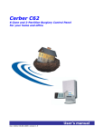
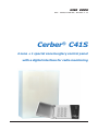
Cerber® C41S
4 zone + 1 special zone burglary control panel
with a digital interface for radio monitoring
Cerber® C41S
USER MANUAL
Table of Contents
INTRODUCTION ........................................................................................................... 3
Basic featues ....................................................................................................................... 3
Technical specifications ...................................................................................................... 4
OPERATION ................................................................................................................. 5
Operation Codes .................................................................................................................. 6
Installer Programming Code ("0269" by default) ................................................................. 6
Arming .................................................................................................................................. 6
Instant perimeter arming ("Instant stay") ...................................................................... 7
Perimeter arming ("Instant stay") .................................................................................. 7
Quick Arming Modes (no code required) ............................................................................ 8
Quick arm, completed .................................................................................................... 8
Quick arm in Instant Parameter Mode ........................................................................... 8
Quick arm in Parameter Mode ....................................................................................... 8
Disarming .............................................................................................................................. 8
Miscellaneous ...................................................................................................................... 9
Zone bypassing ............................................................................................................. 9
System State Display .................................................................................................... 9
Alarm Memory Display ................................................................................................. 10
Door Chime On/Off ...................................................................................................... 10
Program/Modify User Codes ....................................................................................... 11
Monostable activating command ................................................................................. 12
Keypad alarms ............................................................................................................. 12
Operation briefing .............................................................................................................. 13
Warning Limitations of this Alarm System ......................................................................... 15
2
Cerber® C41S
USER MANUAL
INTRODUCTION
BASIC FEATURES
Cerber C41S is a digital interfaced alarm control panel for small and medium
objective radio monitorization. It is ideal for flats, villas, company
headquarters where a local burglary system or remote radio central station
monitorization is needed.
Cerber C41S is a keypad operated burglary system, with built-in monitoring
facilities, alarm memory (the first 9 events could be displayed on the
keypad), 1 Installer code, 1 Master code, 14 user codes and 1 Duress code.
The system multiple facilities are KP-04LED keypad programmable.
The central unit is up-dated and RISC microprocessor designed. The electric
scheme also includes an EEPROM memory. Thus, the programmed
parameters are retained even after all power was removed from the control
panel.
The next basic features are common to the system:
4 EOL zones programmed as Prewarning, Entry/Exit, Instant, Follower, 24
hour "tamper", 24h medical emergency, 24h fire, 24h panic;
• 1 special EOL zone programmed as 24h "tamper", 24h medical emergency,
24h fire, 24h panic, (keyswitch) arming/disarming;
Keypad programming;
• 1 programmable user code;
• 1programable Master code;
14 user codes+1 Duress code (all programmable);
Quick arming, Stay arming, Instant stay arming
• 4 zone attributes, each individually programmable;
Zone Bypass.
Programmable Chime function.
Programmable Bell cut-off time: Steady, Pulse or Silent (programmable
alarming periods);
Programmable Entry delay, Exit delay
Optional Keyswitch arming/disarming.
3
Cerber® C41S
USER MANUAL
9 options for 5 programmable outputs which are: Latch on alarm, Arming/Disarming, Entry delay, Exit delay, Trouble, Steady siren, Pulsing
siren, Silent alarm, Panic, Monostable;
Monostable programmable output enabling for all user codes;
Alarm memory - the first 9 alarm events are displayed on keypad;
2 Digital outputs (CLK and DATA) used for radio transmission;
Monitoring system, battery and AC power state
Individual state LEDs for 1 to 4 zones, indicating the alarm state
System state LEDs: READY, SYSTEM, ARMED;
• Current limitation for back-up battery loading (220mA).
TECHNICAL SPECIFICATIONS:
Power
12V/4Ah battery;
• 14Vac/20VA power transformer
stand-by current:
- control panel: 100mA
- keypad: 12mA
2A maxim power output on AUX power supply, tipical 1A, 2,2A protected.
Inputs
4 fully programmable 2K2 EOL zones.
1 Keyswitch and all 24h type 2K2 EOL zone.
Main board outputs
• 5 "open-collector" outputs with negative trigger (NPN transistors), max. 400mA
(PGMs);
2 "open-collector" outputs with negative trigger (NPN transistors), max. 5,
CLK and DATA;
1 "open-collector" siren output with positive trigger (PNP transistor)tipical
consumption 500mA, max. 1A
4
Cerber® C41S
USER MANUAL
OPERATION
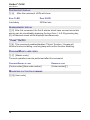
Zone LEDs
READY LED
SYSTEM LED
ARMED LED
The keypad is the device which helps program the system, enter data and
display system state.
System operation is done using the keypad and the indications of LEDs
located in front of the keypad. There are 4 zone LEDs and 3 state LEDs
(READY, SYSTEM, ARMED) on the keypad.
OPERATION CODES
The system recognizes 1 Master code (code 0), 14 user codes (codes 1 to
14 if they have been programmed), 1 Duress code (code 15 - necessary in
case of transmission to a central station) and 1 special code - installer code.
Master code (code 0) - is programmed by default. The default value for the
Master code is "1234". Using the Master code, one can operate the system
and program the other user codes as well.
The allowed operations are: Arming, Disarming, Zone Bypass, Zone Bypass
Cancelling, Operating code programming, Monostable PGM output enabling.
User codes (codes 1 to 14) - not programmed, by default.
The allowed operations are: Arming, Disarming, Zone Bypass, Zone Bypass
Cancelling, Monostable PGM output enabling.
Duress code/Ambush (code 15) - not programmed, by default. If the control
panel also uses the transmission to a central station, when disarming the
system using code 15, the panel will transmit a special code meaning that
the system was disarmed under threat.
If radio transmission is not used, code 15 can be used as any other user
code.
Code modifying, including Master code, is done by [*][7][Master Code]
command.
5
Cerber® C41S
USER MANUAL
INSTALLER CODE ("0269" BY DEFAULT)
Only the system installer is entitled to have this code. Making use of this
code, the installer has access to the system parameter programming menu,
except user functions. The default Installer Code is 0269.
Control panel parameter programming is achieved by this code and the
[*][8][Installer's code] command, only if the control panel is disarmed
(system user's agreement is necessary).
This code should be changed after system installing!
Note: The control panel is provided with an option for valid code "guessing"
attempts without regards to the type of code (Master, user, installer). After
successively entering 10 wrong codes, the keypad will no longer take
commands for the next 8min.
ARMING
USER
CODE
In order to arm the system enter a 4 digit user code. When pressing each
digit, the keypad buzzer will emit a short beep.
After entering the user ode, "ARMED" LED will turn on, and the keypad
buzzer will emit 6 beeps.
If the user code is wrong, the keypad buzzer will emit a long beep. Press [#]
and start entering the code again.
After entering the user code and "ARMED" LED turning on, exit the objective
through Entry / Exit zone before exit time was over. After exit time was over,
all LEDs will turn off but "ARMED" LED.
Exit time value is 120s by default. In order to chande it, see section [06] System parameter programming menu.
Before arming the system, make sure that all protected zones (doors and
windows) are closed. Leave the rooms protected by PIR detectors.
If System LED is lit, check the following:
- the alarm memory ([*][5] command). If there are alarms in the memory, they
will be cleared when arming the system.
- bypassed zones ([*][3] [User code] command). Make sure that all zones
displayed as being bypassed are intentionally bypassed.
- system state ([*][4] command). If there is trouble with the battery or the
220Vac power, fix them before arming.
If "READY" LED is not lit, then one or more zones are open. The system
cannot be armed unless "Ready" LED is lit.
6
Cerber® C41S
USER MANUAL
INSTANT PERIMETER ARMING (INSTANT STAY)
[*] [1] [USER CODE]
This arming mode is used for perimetral protection. Thus, the user can stay
inside the protected area (i.e.: arming the panel at night while staying home
and no guest is expected).
After pressing the user code, the system automatically isolates the
"STAY" zones inside the house. That is why the yellow "System" LED will
turn on during exit delay. After the Exit time was over, "delayed" zones will
become "Instant" and they will trigger an alarm the very moment they are
opened. Perimeter zones are those which have not been designated as
"STAY" type by the installer.
The red "Armed" LED will blink, instead of being steady, indicating that the
"delayed" zones are "instant" now.
PERIMETER ARMING ("STAY)
[*] [2] [USER CODE]
This arming mode is also used for perimetral protection. This time the user
also stays inside the protected area, but is allowed access through the
Entry/Exit zones.
After pressing the user code, the system automatically isolates the "STAY"
zones inside the house. Thus, the yellow "System" LED will turn on
during Exit delay. After the Exit time was over, the whole system will arm in
a perimeter mode, Entry/Exit zones keep their characteristics and the
"Armed" LED will stay lit.
Any code user (1..15) can enter the building thruogh Entry/Exit zones. During
the entry lapse of time the code user may enter his/her own code in order to
disarm the system.
7
Cerber® C41S
USER MANUAL
QUICK-ARMING MODES (NO CODE REQUIRED)
This function will be used by someone who doesn't own an access code.
This arming mode can also be used when arming in presence of someone
who must not finf out the user code.
QUICK ARM, COMPLETED
[*] [0] [0]
Arming will be done by pressing the sequence [*][0][0]. Next, the user should
leave the protected area before Exit time was over. After the Exit time was
over, the whole system will arm and the "Armed" LED will stay lit.
QUICK ARM IN INSTANT PERIMETER MODE ("QUICK INSTANT STAY")
[*] [0] [1]
Similar to Instant Perimeter Arming "INSTANT STAY".
QUICK ARM IN PERIMETER MODE ("QUICK STAY")
[*] [0] [2]
Similar to "STAY" arming .
DISARMING
[USER CODE]
One can only enter the protected area through an Entry/Exit zone. While
opening Entry/Exit zone, Entry time will begin counting.
Keypad buzzer will sound a continuous beep during the Entry time, indicating
that the system should be disarmed.
Press one of the access codes 1 to 15. . If wrong, press [#] key and repress
the code again.The "Armed" LED will turn off and so will the buzzer.
If the system is not disarmed during the Entry time, the panel will alarm.
Note: In order to modify the Entry time, see system parameter programming,
section [06].
8
Cerber® C41S
USER MANUAL
MISCELLANEOUS
ZONE BYPASSING
[*] [3] [USER CODE]
Zone bypassing can be done only if the system is disarmed.
The initiating devices from a bypassed zone will not be considered by the
panel. Zone bypassing is used when access is needed in that particular zone
even if the system is armed, a sensor is out of order or wiring is defective.
Zone bypassing is also used when some initiating devices or wires are
damaged and restoring is not immediately possible .
Arming can be done having one or more zones bypassed even if sensors on
these zones are open.
While the system is disarmed, press [*] [3] [Access code] to display the
bypassed zones. The "System" LED will blink and the corresponding zone
LEDs will be lit.
To bypass a zone, press the corresponding digit while the corresponding LED
will turn ON. To cancel zone bypassing, press the corresponding digit while
the corresponding LED will turn OFF. If the zone corresponding to the key
pressed does not have the feature "able to be bypassed" set up (this feature
can be modified as in sections 01 - 04), bypassing will not be allowed which
is confirmed by a long beep fro the keypad buzzer and the LED
corresponding to that key will still be off.
Note! 24h zones cannot be bypassed. If one 24h-zones (one of 1 to 4
zones) had the "able to be bypassed" feature set up before having declared it
a 24h one, then when entering [*] [3] [User code] sequence, the keypad will
confirm 24h-zone bypassing. However, the 24h-zone will not be actually
bypassed.
Exit bypassing mode by pressing [#].
NOTE: When disarming the system, the bypassed zones will be cleared.
SYSTEM STATE DISPLAY
[*] [4]
The alarm system monitors some trouble conditions. If one of these
conditions occurs, the "System" LED will turn ON.
To display these conditions, press [*] [4]. The conditions will be displayed on
zone LEDs as follows:
Zone 1 LED - Low Battery: if the battery is disconnected or LOW, this LED
is lit. The LED will turn OFF within 8 seconds after restoring the battery
9
Cerber® C41S
USER MANUAL
trouble.
Zone 2 LED
- AC Power OFF: if AC power is OFF or the transformer is
burnt, this LED is lit. The LED is also lit if AC power circuit fuse is burnt. The
LED will turn OFF instantly after restoring AC power trouble.
To exit this mode press [#] key.
ALARM MEMORY DISPLAY
[*] [5]
The first 9 alarms produced during the last arming are memorized and can be
visualized on the keypad LEDs. To display the alarmed zones press [*] [5].
"System" LED will blink and so will the LEDs of the last alarmed zones (1 to
4). One can press 1 to 9 keys in order to visualize the first 9 alarmed zones
during the last arming of the panel. Pressing the key [1] one of zone LEDs
will turn on showing the first zone alarmed, while pressing the key [9] one of
zones LEDs will turn on showing the most recently alarmed zones.
Note: LED interpreting when presing one of the keys from 1 to 9 is done as
follows:
1) If LED 1 is lit and "SYSTEM" LED is blinking, "READY" LED is off - then
an alarm has occured in zone 1.
2) If LED 2 is lit, "SYSTEM" LED is blinking, "READY" LED is off - then an
alarm has occured in zone 2.
3) If LED 3 is lit, "SYSTEM" LED is blinking and "READY" LED is off - then
an alarm has occured in zone 3.
4) If LED 4 is lit, "SYSTEM" LED is blinking and "READY" LED is off - then
an alarm has occured in zone 4.
Pressing the key [0] one can see all the alarmed zones simultaneously.
To exit this display mode press [#] key.
The alarm memory will clear while arming the panel again.
DOOR CHIME ON/OFF
[*] [6]
The Door Chime feature causes the keypad buzzer to sound 6 short beeps
whenever an Entry/Exit door is activated. The feature is useful if the Entry/
Exit doors are out of view and the user desires an indication of when the door
zones are opened.
The Door Chime feature works only when the system is disarmed.
To turn the feature on/off enter [*] [6] command. If the feature is being turned
10
Cerber® C41S
USER MANUAL
ON, the keypad buzzer will emit 3 beeps. If the feature is being turned OFF,
the keypad buzzer will sound 6 beeps.
Note: "Chime" feature is disabled by default.
MODIFY/PROGRAM ACCESS CODES (1...15)
[*] [7] [MASTER CODE]
The [*] [7] [Master Code] command allows Master user to modify all user
codes but the installer code.
Enter [*] [7] [Master Code].
Ready LED will be off, Armed LED will be lit, System LED will start
blinking, and zone LEDs are off.
In order to choose the code to be entered/modified, enter the 2-digit code
order number (i.e. for Code 7 enter 07). this very moment the keypad will emit
3 beeps, and zone LEDs will act as follows:
Note:
1) If 1,2,3 and zone LEDs are blinking, then the code has already been
programmed.
2) If only zone 1 LED is blinking, then the respective code is not
programmed.
3) When the code is being programmed, 1 and 2 zone LEDs are lit, and
"READY", "SYSTEM" and "ARMED" LEDs are blinking.
From this moment on, the codes are to be modified as follows:
Changing or Adding a Code
Code entering or changing can be cancelled by pressing [#].
A new code can be entered if the next sequence will be entered by keypad:
/X/X/X/X/
where:
/ X / X / X / X / is the new 4-digit user code.
In order to issue another code, its order number will be entered and the
procedure will be resumed.
All 15 user code can be thus added or modified.
Note: Do not press [*] when entering the code.
11
Cerber® C41S
USER MANUAL
Erasing a Code
After entering a code order number, the keypad buzzer will emit 3 beeps and
1, 2, 3 and 4 zone LEDs will blink if the respective code does exist. If the
respective code has not been previously programmed, only zone 1 LED will
blink.
If the code does exist, in order to erase it press [*], this key being the first
one to be pressed after the order number was entered. In this case, the
keypad buzzer will emit 6 beeps. If [*] key is not the first one to be pressed
but the second, the third or the fourth, the current code will not be erased,
the old code being kept. In this case, the keypad buzzer will emit a long
beep.
Erasing all codes
If {2] [0] keys are pressed, all codes will be erased but "Master" code.
The keypad will emit 6 beeps.
NOTE: Never erase Master Code! If, by mistake, the Mater Code is erased,
reset system programming to factory default settings (see Commissioning).
In this programming/modifying mode, "Ready", "System" and "Armed"
LEDs will blink continuously.
After having completed all desired changes, exit this programming/modifying
mode by pressing [#].
MONOSTABLE ACTIVATING COMMAND
[*] [9] [USER CODE]
When activating this command, any output (PGM1, PGM2, PGM3, PGM4
and PGM5) programmed as monostable will activate (by negative triggering)
during the programmed lapse of time (in section [9], system parameter
programming menu).
KEYPAD ALARMS
These events can be performed by pressing some keys simultaneously:
[1] and [3]
Medical emergency alarm
[7] and [9]
Fire alarm
[4] and [6]
or [*] and [#]
Panic alarm
12
Cerber® C41S
USER MANUAL
Note:
1) When the event Emergency Alarm is keypad generated, the next will
activate:
- "Silent" siren (will not be heard).
- PGMs programmed with Silent Alarm feature (value 7 in section [9] Programmable 1-5 PGM output type during active siren period, even if it is
silent).
2) When the event Fire Alarm is keypad generated, the next will activate:
- Pulse siren.
- PGMs programmed with Pulse Alarm feature (value 6 in section [9] Programmable 1-5 PGM output type) during active siren period.
3) When the event Panic Alarm is keypad generated, the next will activate:
- Steady siren.
- PGMs programmed with Pulse Alarm feature (value 5 in section [9] Programmable 1-5 PGM output type) during active siren period.
OPERATION BRIEFING
ARMING
[User code]
[*] [0] [0]
[*] [0] [1]
[*] [0] [2]
[*] [1] [User code]
[*] [2] [User code]
Normal arming
Comlpeted quick arm
"QUICK INSTANT STAY"
"INSTANT STAY"
"Instant stay" arming
"Stay" arming
DISARMING
[User code]
ZONE BYPASSING
[*] [3] [User code]
By pressing the corresponding keys, bypassing is enabled/disabled.
13
Cerber® C41S
USER MANUAL
SYSTEM STATE DISPLAY
[*] [4]
After this command, LEDs will show:
ZONE 1 LED
ZONE 2 LED
Low batery
220Vac loss
ALARM MEMORY DISPLAY
[*] [5] After this command, the first 9 alarms which have occured since last
arming can be visualisedby pressing the keys from 1 to 9. By pressing key
[0], all alarmed zones will be displayd simultaneously.
"CHIME" ON/OFF
[*] [6] This command enables/disables "Chime" function. 3 beeps will
confirm function enabling, one long beep will confirm function disabling.
PROGRAM/MODIFY USER CODES
[*] [7] [Master code]
The next operations can be performed after this command:
CHANGING/ADDING A CODE
ERASING A CODE
[Code number] [New code number]
[Code number][*]
MONOSTABLE ACTIVATION COMMAND
[*] [9] [User code]
14
Cerber® C41S
USER MANUAL
WARNING LIMITATIONS OF THIS ALARM SYSTEM
Since this system is an advanced design security system, it does not offer protection against burglary, fire or other emergency
but warning. Any alarm system, whether commercial or residential, is subject to compromise or failure to warn for a variety of reasons. For
example:
Intruders may gain access through unprotected openings or have the technical sophistication to bypass an alarm sensor
or disconnect an alarm warning device.
Intrusion detectors (e.g. passive infrared detectors), smoke detectors, any many other sensing devices will not work without
power. Battery operated devices will not work without batteries, with dead batteries or if the batteries are not put in properly. Devices powered
solely by AC will not work if their AC power supply is cut off for any reason, however briefly.
A user may not be able to reach a panic or emergency button quickly enough.
Smoke detectors may not activate or provide early warning for a variety of reasons. Some of the reasons smoke detectors
used in conjunction with this system may not work are as follows> Smoke detectors may have been improperly installed and positioned. Smoke
detectors may not sense fires that start where smoke cannot reach the detectors, such as chimneys, in walls, or roofs, or on the other side
of closed doors. Smoke detectors may not sense a fire on another level of a residence or building. A second floor detector, for example, may
not sense a first floor or basement fire. Moreover, smoke detectors have sensing limitations. No smoke detector can sense every kind of fire
every time. In general, detectors may not always warn about fires caused by carelessness and safety hazards like smoking in bed, violent
explosions, escaping gas, improper storage or flammable materials, overloaded electrical circuits, children playing with matches, or arson.
Depending on the nature of the fire and/or the location of the smoke detectors, the detector, even if operates as anticipated, may not provide
sufficient warning to allow all occupants to escape in time to prevent injury or death.
Passive Infrared Motion Detectors can only detect intrusion within the designed ranges as diagrammed in their installation
manual. Passive Infrared Detectors do not provide volumetric area protection. They do not create multiple beams of protection, and
intrusion can only be detected in unobstructed areas covered by the beams. They cannot detect motion or intrusion that take place behind
walls, ceiling, floors, closed doors, glass partitions, glass doors or window. Mechanical tampering, masking, painting, or spraying of any
material on the mirrors, windows or any part of the optical system can reduce their detection ability.
Alarm warning devices such as sirens, bells or horns may not alert people or wake up sleepers who are located on the
other side of closed doors. If warning devices sound on a different level of the residence from the bedrooms, then they are less likely to
waken or alert people inside the bedrooms. Even persons who are awake may not hear the warning if the alarm is muffled by noise from
a stereo, radio, air conditioner or other appliances, or by passing traffic, Finally, alarm warning devices, however loud, may not warn
hearing-impaired people or waken deep sleepers.
Telephone lines needed to transmit alarm signals from a premises to a central monitoring station may be out of service
or temporarily out of service. Telephone lines are also subject to compromise by sophisticated intruders.
Even the system responds to the emergency as intended, however, occupants may have insufficient time to protect
themselves from the emergency situation. In the case of a monitored alarm system, authorities may not respond appropriately.
The most frequent cause of an alarm system not functioning when an intrusion or fire occurs is inadequate maintenance.
This alarm system should be tested weekly to make sure all sensors are working properly.
15
ROMANO ELECTRO INT'L
27-29 Calimachi Str., Sect. 2, 72266,
Bucharest, ROMANIA
Tel.: 40-1-242.20.20, Fax: 40-1-242.20.30,
E-mail: [email protected], www.roel.ro