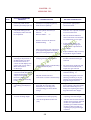
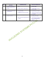
1
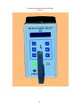
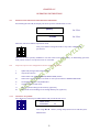
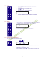
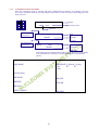
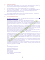
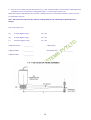
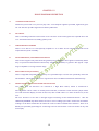
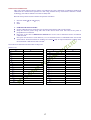
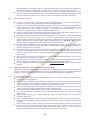
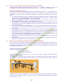
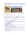
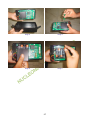
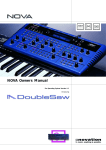
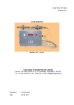
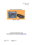
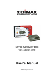
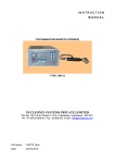
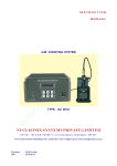
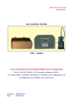
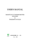
IN STRUCTION MAN UAL MICRO – R – SURVEY METER TYPE : UR705 NUCLEONIX SYSTEMS PVT. LTD. Plot No. 162 A&B, Phase-II, I.D.A. Cherlapally, Hyderabad - 500 051. Ph : 040-27263701, 32908055 Fax : 040-27262146, e-mail : [email protected]. www.nucleonix .com File Name : UR705_Man Date : 12-05-2014 CONTENTS S.No Description Page No. CHAPTER I Introduction & Applications 01-01 CHAPTER II Specifications 02-02 CHAPTER III Front panel & side panel controls 03-04 CHAPTER IV Operating Instructions 4.1 Instructions on intelligent keypad commands 05-09 4.2 Operating procedure 10-10 4.3 How to make measurements 10-10 CHAPTER V Calibration 11-12 CHAPTER VI Block Diagram & Description 13-14 CHAPTER VII RS232 Data communication 15-15 CHAPTER VIII Calibration Certificate & QA Report 16-19 CHAPTER IX Servicing Tips 20-21 CHAPTER X Availing of maintenance / calibration services and 22-27 warranty clause (with in India) CHAPTER- I INTRODUCTION Micro-R Survey Meter Type : UR 705 manufactured by NUCLEONIX SYSTEMS is primarily designed to measure low level Gamma and X-radiation. This Portable Survey Meter, designed around integrally coupled 1" x 1" NaI(Tl) Scintillator to a 1 1/2" PMT, will offer an optimum performance in counting Low-Level Gamma Radiation dose rate. This unit can measure and display dose rates in the range of 0-10000 R/hr on a dot matrix LCD Display. Dose rates close to natural background levels can be measured accurately. This unit is ideally suitable for Radiometric and Environmental Radiation Monitoring involving low-level radiation dose rates. This unit employs microcontroller based design and has number of unique features. User can store upto 1000 readings at the press of a button and can recall back, for visual indication on a dot matrix LCD display. This unit is provided with a built-in RS232 port (optionally) through which the stored data can be down loaded into PC. Some important features of this unit are : Microcontroller based design Compact, elegant and light weight User can store upto 1000 readings Detects Gamma and X radiation Measures dose rate from 0-10000 R/hr High Range (or) 0.01 to 99.99 Sv/hr Detector : 1" x 1" x 1 1/2" NaI (Tl) Detector probe assembly is built into the instrument enclosure box TTL 232 serial port (built-in), USB cable extra (Optional) Built in audio Works on 6V DC dry cells APPLICATIONS This is an ideal choice for the measurement of (i) Background / Natural background radiation levels, (ii) Environmental radiation in different terrarin, including underground mines. Apart from this above application, it can be used to measure increase in radiation levels in buildings, houses, offices & in building materials etc, in a Nuclear accident / disaster scenario. Further one can check the contamination of food stuffs (meat, fish, vegetable, cereals) & items in solid form, by placing them in a polyethylene pouch (approx 1kg of stuff in front of the meter very close to front face of the meter. (Detector sensitive part is towards front end). Care should be taken not to contaminate the meter body while making measurement. Additionally, in Radiological installations, reactor buildings etc. also this can be used where one would like top measure low level dose rates. 1 CHAPTER - II SPECIFICATIONS Detector (options) : (a) Nal (Tl) Scintillator, 1"d x1"h coupled to a Photomultiplier Tube. Detector assembly is inside the survey meter enclosure. (b) External unit through 1mtr cable Calibration Accuracy : (a) Better than +/-10% (specified with a Cs-137 standard source) from 100 R/hr onwards (b) Within +/-20% upto 10000 R/hr Acquisition mode : CPS : 0-50000 CPM: 0-5000 Dose Rate (mode) : 1-10000 R/hr or 0.01-100.00 Sv/hr Over Range : This instrument will show over range above the 10,000 R/hr Data Storage : Can store upto 1000 data readings. Stored data can be recalled back on to display. Display Indication : Dot Matrix LCD display for dose rate / cum dose. Sensitivity : 1 R/hr or 0.01 Sv/hr Serial Port (optional) : Built-in serial port facilitates data down loading into PC. Data Communication Software with connecting cable can be provided at extra cost as an additional option. User Interface : START, STOP, PROG, STORE, INC, DEC, POWER ON command buttons for setting of parameters & operation of the instrument. Power : 6 volts DC, BPL Excell or DURACELL ULTRA, Size AA, MN1500 LR6 (4 X 1.5 Volts), Alkaline cells. Dimensions : 106W x 196L x 100Ht in mm (Approx.) Weight : Unit with detector (1"x1" NaI): 2kg 2 CHAPTER - III FRONT PANEL & SIDE PANEL CONTROLS 3.1 FRONT PANEL CONTROLS AND INDICATIONS 3.1.1. LCD DOTMATRIX DISPLAY This is a 16 X 2 alpha numeric LCD dot matrix display and responds to all the commands from the keypad and displays programme parameters like Acquisition modes (BG, CPS, CPM, DOSE RATE, PRESET TIME), TC, Recall, Save etc. 3.1.2. INTELLIGENT KEYPAD (a) PROG key button: This key is an important one which facilitates the user to programme the operation of the instrument for different modes / conditions. (b) START key button: This is used for starting of acquisition once all the programme parameters have been set. (c) STOP key button: This key can be used to stop acquisition. (d) INC/DEC key button: These keys are used while setting the programme parameters to increment/decrement a value or to change the option selected to another value available. (e) STORE key button: This key is used for storing the readings or data values in the following way. (f) Power ON key button: This key is used for the unit to put ON/OFF. If you want to store the data, then press STOP button to stop acquisition and then press STORE button. Note: Keypad commands have been explained in detail under chapter V - 5.1. 3.1.3. TTL 232 (OPTIONAL AT EXTRA COST) This connector is having TTL 232 compatible signals for serial data communication to a P.C. Under software control from a P.C, the stored data reading from this unit can be down loaded on to P.C. 3 VIEW OF MICRO-R SURVEY METER UR705 4 CHAPTER -IV OPERATING INSTRUCTIONS 4.0 INSTRUCTIONS ON INTELLIGENT KEYPAD COMMANDS On switching the unit ON, the display will show up below initialization screens. UR-705 (MICRO) NUCLEONIX for 3 Sec. SYSTEMS for 3 Sec. After this, unit enters default acquisition mode. Now press STOP to change the mode or any other configuration parameters. This unit has been specially modified to suit the needs of the steel industry. It additionally generates audio/visual alarms in case preset levels are exceeded. 4.1 Step wise sequence for configuration and use of the survey meter i. Update BG (background radiation level) ii. ACQ mode selection Select either CPS, CPM, DOSERATE, PRESET TIME, modes 4.1.1 iii. Select time constant for doserate mode or select preset time for PRESET TIME mode iv. Set ALARM LEVLE for CPS/CPM modes v. Acquire in the selected mode vi. Store acquired readings in the memory (optional) vii. Download stored readings to PC through RS232 port (optional) TO SELECT ACQ MODE Press STOP key and now press PROG button and you will be able to see MENU ACESS PASSWORD : 00 Now using orbuttons, change the password to 90 and then press PROG button. 5 4.1.2 TO SELECT ACQ MODE Press PROG key to select below menu option ACQ MODE XXXXXX Now using orbuttons, select suitable menu option - CPS, CPM, DOSERATE. 4.1.5 STORING OF ACQUIRED READINGS To store last acquired readings into the memory press STORE button while acquisition is going ON for DOSERATE, CPS & CPM modes 4.1.6 TO SET THE LABLE FOR A CORRESPONDING READING By using this feature user can give code numbers to different locations when making measurements on field. LABEL XX Code number By using orkeys code number can be changed to 00 to 99. 4.1.4 TO SELECT UNIT FOR MEASUREMENT To select Unit for measurement UNT R/h Now using orbuttons, to select Sv/h 4.1.7 CALIBRATION This is a very useful & important feature, it allows one to calibrate the unit to obtain expected dose rate for the type of the scintillator used. This is to be changed only if user intends to recalibrate the unit. CAL. FACT 01.00 6 4.1.3 TO SELECT THE RANGE To select time constant for doserate mode after selecting 'DOSERATE' mode in the 'ACQ MODE' menu, press PROG to select below menu option RANGE SELECTION XXXXX Now using orbuttons, select suitable TC - LOW, MED or HIGH TC 4.1.8 BUZZER On pressing PROG key the following display appears, BUZZER OFF The default buzzer condition is OFF. User can change this by pressing orkeys. BUZZER 4.1.9 ON RECALL DATA READINGS This is a very useful feature that has been provided in this unit. At the end of storing/saving of a set of readings, this feature will enable the users to recall the readings on to the display, from the Sl.No. Set in the "RECALL" mode. Changing of the Sl.No. is similar to that explained under "SL. NO." selection. By pressing PROG key, display changes to, Recall Time Date R XX.XX XX/XX XX Lable XXX XXXXXX R/hr Unit Sl.No Doserate 7 4.1.11 SAVE? • • • • • After changing all program parameter you can save those parameters. Press STOP key Press PROG key unit you get SAVE? option Press orkey You will observe on display as shown below SAVE ? OK • Then press START key to start acquisition in selected mode 4.1.12 ERASE ? If user wants to erase the stored memory press stop key & then PROG to get ERASE parameter then press orkey you will see as ERASE ? OK Then again go for START to acquire in selected mode. 4.1.10 TO SET RTC OF THE INSTRUMENT Press PROG button to select below menu option Date Time RTC ^ XX:XX XX/XX Here the RTC is displayed in HH : MM dd/mm format and the time is in 24hr mode (i.e. 1:00 PM will be 13:00) Now to set the RTC, using orbuttons and set it to a desired value. 8 4.1.4 ACQUIRING IN SELECTED MODE Once the acquisition mode is selected and other configuration parameters are selected, user may proceed to acquisition mode by pressing START button below screens will appear depending upon the mode selected. DOSERATE DOSERATE AA Blink Doserate units XXXXXmR/h mR/h XXXXX Doserate Status message clean/alarm XXXXX CPS A XXXXXX Blink CPS mode CPS value Status message clean/alarm XXXXX CPM A XXXXXX Blink CPM mode CPM value Depending upon the minimum detectable level or on occurrence of alarms user may decide on accepting / rejecting the material (scrap/finished goods). MENU - OPTIONS ACQ MODE - DOSERATE ( R/hr & Sv/hr) CPS CPM SL.NO (A/O) - - RECALIB? - NO/YES BUZZER - OFF/ON RECALL - - SAVE ? (PROG) - OK/SKIP 9 4.2 OPERATING PROCEDURE 1. This unit is packed and dispatched in ready to use condition. On unpacking, user is advised to go through Instruction Manual including instructions under Chapter V (5.1) completely. 2. Now switch ON the power to the unit by pressing the Rocker switch to the ON position. 3. User can now operate the equipment to make measurements in CPS/CPM or DOSERATE ( R/hr & Sv/hr) modes as per the requirement. User can store and recall the readings if required also. 4. Optional feature (offered against specific order only) : Stored readings can be downloaded into a PC if required under the control of data communication software which is supplied at extra cost as an optional accessory. 4.3 HOW TO MAKE MEASUREMENTS Since this is a sensitive low level survey meter (Micro-R Level) it is necessary for one to know the natural background radiation levels at that place. Measurement can be done in mR/hr, mSv/hr CPS or CPM as desired by the customer. For measuring natural background levels, take the unit to outdoor area & hold at least 1 meter above the ground level and 1 metre away from side walls observe the natural background (BG) reading. Make about three measurements & take average of the three readings & that should be treated as the natural B.G. Now for making actual measurements, especially to detect radioactive contamination of a sample (which may be a raw material input of steel /iron/alloy of steel or iron, scrap, castings etc., or a finished product) hold the meter in ‘ON’ condition close to the sample for one time constant (TC) at least and observe the reading. Also record two more successive readings and see the average. This reading may be same as natural background if variation in reading is more than 30 to 40% of above preset levels, sample may be contaminated with radioactive materials. Important note: Before making sample measurements indoor or in a room/shed/workplace take background reading in that place without any sample, preferably by placing the meter on a table or at a table height. Or at a height where you would like to make actual sample measurements. Let this be treated as your actual Background for measurements. This background you may find it higher than outdoor background, because of closed room, background radiation from the walls, flooring etc may add up. Now place the meter close to the sample under measurement & note the meter reading. If this reading is slightly less that the background, equal to background or 1.2 to 1.3 times the background then you can declare the sample to be radioactive contamination free. If you find the reading to be more than 1.5 times the background then you can suspect the sample to the contaminated & through checkup is to be carried out and the matter may please be reported to the Atomic Energy Regulatory Board. (AERB) To Head, Radiological Safety Division, Atomic Energy Regulatory Board, Niyamak Bhavan, Anushaktinagar, Mumbai – 400 094. Ph : 022-25574287 Fax : 022-25565717, 25562344, 25583230 Mobile : 9820864880 10 CHAPTER -V CALIBRATION PROCEDURE FOR CALIBRATION WITH SOURCE : This unit namely Micro-R Survey Meter type UR705 has been calibrated at Radiation Standard & Calibration Lab of Nucleonix Systems (P) Ltd., using Gamma Survey Instruments Calibrator of AEA Technology, USA. This standard is traceable to NIST, USA. UR Survey Meter has three modes of operation (i.e.,) CPS, CPM and dose rate mode (0-10000 mR/hr in Low Range & 0.1– 200 mR/h) for gamma radiation. a) Calibration in CPS/CPM mode : CPS & CPM are calculated based on a fixed time constant. This time constant is accurate and no adjustment is needed. Hence data displayed on LCD display in CPS/CPM can be treated as correct irrespective of calibration. b) Calibration in Dose rate mode : Initially using a standard source lookup table has been generated for various dose rates as given in the below table. Doserate R/hr CPS 500 1708 800 2390 1000 3075 1500 4125 2000 5225 3000 7214 5000 10707 1"X 1" NAI DETECTOR # This data has been stored in the micro controller firmware. Based on this lookup table, for different frequencies generated by the detector corresponding dose rate will be calculated from the lookup table and displayed on the LCD display depending upon the selection of input. # Now set the calibration factor to 1.00 by using program keys of the instrument and save the new setting. # Now select HIGH TC in dose rate mode of operation and acquire by keeping the detector at different positions. # Keep the detector probe in the source beam such that axis of the Plastic Scintillator is perpendicular to the beam. # Now refer to the distance Vs dose rate chart of Cs-137 source of Radiation calibration Lab I (chart preparation date should be < 15 days old), if calibrated at NUCLEONIX SYSTEMS. # Now place the monitor at below dose rates and record observations. If observed dose rate is within +/15% of expected dose rate, the instrument is said to be calibrated. # Distance of source to axis of Plastic Sintillator crystal is to be taken for making the below measurements. Very Important Note: Please note that for a required dose-rate, always choose to keep detector probe at maximum possible distance from source with minimum no. of lead block attenuators. This is to prevent scattering effect due to attenuator blocks at close distances (< 50 cm) 11 # Now in case a reading exceeds the tolerance of +/- 15%, of expected dose rate then adjust calibration factor of monitor such as to make entire readings fall within +/- 15% of expected dose rate. When the manual is dispatched to the customer, calibration factor is to be mentioned below and also saved in the instrument program. Note : This instrument will show the constant reading 10000 m R/hr indicating the OVR in the 16x2 Display. Over Load test passed : (a) 10 times highest range Yes / No (b) 50 times highest range Yes / No (c) 100 times highest range Yes / No Calibration Factor : ________________ Calibrated by : __________________ Calibration Date : ________________ Instrument S.No. : __________________ Calibration Due : ________________ 12 CHAPTER -VI BLOCK DIAGRAM DESCRIPTION A. +5V REGULATOR OUTPUT Unit draws power from +6V (1.5V x 4) dry cells. A low dropout regulator provided, regulates & gives out +5V. This also provides signal for low battery indication. B. HV CIRCUIT This is a blocking oscillator based on DC to DC converter circuit which generates required HV to the 1”x1” Scintillation detector assembly, gamma probe. C. GAMMA DETECTOR PROBE This is a 1”x1” NaI or 2" x 2" NaI optically coupled to 1” or 2" PMT. Also it contains HV bleeder circuit required for the probe assembly. D. PULSE AMPLIFIER / DISCRIMINATOR CIRCUIT This receives negative tail pulses from the gamma probe & amplifies these signals considerably before they are passed into discriminator followed by which to monostable, to generate TTL signals. Input stage of amplifier is a charge sensitive stage. E. REAL TIME CLOCK (OPTIONAL) This is a single RTC chip with battery backup. It is provided only in case the user specifically orders the unit with RTC. This facilitates the user to log and store dose rate & RTC information simultaneously. F. MICROCONTROLLER & ASSOCIATED CIRCUIT BLOCKS TTL pulses from the detectors are counted in a digit BCD counter, which is interfaced to microcontroller. These counts are read by microcontroller, counted for a Time Constant (TC) & shown on a LCD dot-matrix display in terms of dose rate, CPS or CPM. There is a choice of three TCs, for the user. The user interface to the unit is through keypad consisting of SIX command buttons. Unit has additionally EEPROM chip which allows the user to store readings upto 1000. Further the stored data readings can be down loaded into PC under the control of data communication software. There is an RS232 port provided (optionally) for connecting to PC for data transfer. This unit works on dry cells 4x1.5V (6V). 13 +5V +750V 14 CHAPTER – VII RS 232 DATA COMMUNICATION A) Verify if Windows 7 is installed on Target PC. Nucleonix provides support only for Windows 7. In case, for whatever reason, it is required to demonstrate the software on Windows XP, install the Service Pack 3 (if it is not already installed). 1. Double click on "windowsxp-kb936929-sp3-x86-enu._u5Kng" file in "windows xp service pack3" folder. B) Login with Administrator privileges on your PC. Insert NucSoft software CD and run NucSoft.bat to start installation. The Batch file automatically installs the necessary files. C) NucSoft.bat should have installed NucSoft.xls and NucSoftLogin.xls automatically in C:\. In case you do not find these files in C:\, Copy NucSoft.xls and NucSoftLogin.xls to c:\ D) NucSoft.bat should have installed USB_Serial Bridge drivers automatically. In case it is not installed, Install by 1. Double Clicking on driver.exe in BAFOProlific_USBSerialBridge_Driver folder in CD and follow the steps. E) NucSoft.bat should have installed dotNET framework automatically. In case it is not installed, Install dotNET framework by 1. Double Clicking on dotNetFx40_Client_x86_x64.exe in dotNETClient folder in CD and follow the steps. F) NucSoft.bat should have installed Setup.exe for NucSoft automatically. To verify this, click on Start --> All Program --> Nucleonix Systems. If you do not find NucSoft shortcut, then it means, NucSoft is not installed. Run NucSoft Setup by double clicking on "Setup.exe" application in Debug folder. G) NucSoft should have installed Skype automatically. In case it is not installed, Run Skype Setup by Double clicking on "SkypeSetup" in SkypeSetup folder. Internet Connectivity is required. Skype is required for Remote technical support. H) In case your PC does not have Windows Live Movie Maker / Windows Media Player, Run Windows Live Movie maker Setup by Double clicking on "windowsLiveMovieMakersetup-web" in WindowsLiveMoviemakersetup folder. Internet Connectivity is required. Windows Live Movie Maker is required to play Movie files (Documentation). I) Go through the following Videos to understand the working of NucSoft, before running the application. To locate the Videos, click on Start --> All Programs --> Nucleonix Systems. 1. NucSoft_AboutUs 2. NucSoft_UserManual_SystemRequirements 3. NucSoft_UserManual_MakingConnections 4. NucSoft_UserManual_IdentifyingCOMPOrt 5. NucSoft_UserManual_SoftwareFeatures J) Default Login and password for NucSoft software is 'admin' and 'Nucleonix'. 15 CHAPTER – VIII CALIBRATION CERTIFICATE This is to certify that the following unit(s) has been calibrated at the Radiation Standards and Calibration Lab, using Gamma Survey Instrument Calibrator Model 773 of Nuclear Associate. This calibrator is traceable to NIST, USA. Instrument Name : MICRO-R-SURVEY METER INTERNAL NaI Detector Sl.No. : ________________ Type No. : UR 705 Calibration Date : ________________ Range Covered : 0 – 10, 000 R/hr Calibration Accuracy : Within +/-15% (with Cs-137) Validity : One Year from the date of calibration Over Load Test Passed : 10 times Calibration Factor : ________________ Head of R.S.O Nucleonix Services Division TO 16 RADIATION CALIBRATION: This unit namely Micro-R-Survey Meter type UR705 has been calibrated at Radiation Standard & calibration lab of Nucleonix Systems Pvt. Ltd. using Gamma Survey instruments calibrator of AEA technology, USA. This standard is traceable to NIST, USA. Micro-R-Survey meter has three modes of operation as follows 1. 2. 3. Doserate mode ( R/hr and Sv/hr) CPS CPM 1. Calibration in doserate mode : Set the calibration factor in the unit to 1.00 using program keys and save the setting Keep the detector probe along with unit in the source beam such that axis of the probe is perpendicular to the beam. Now refer to the chart of distance Vs doserate for Cs-137 source calibration device of radiation calibration lab. Now place the monitor at such distances, so as to obtain doserates as tabulated below and record observations. If observed doserate readings are within +15% of expected doserate readings then, the instrument calibration is said to be OK. Note: The chart should not be more than 15 days old. With Cs-137 Expected R/hr 1 R/hr 2 R/hr 5 R/hr 10 R/hr 20 R/hr 50 R/hr 100 R/hr 200 R/hr 500 R/hr 1000 R/hr 2000 R/hr 3000 R/hr 5000 R/hr 8000 R/hr 9000 R/hr 10000 R/hr 15000 R/hr 1000mR/hr Observed R/hr Expected Sv/hr 0.01 Sv/hr 0.02 Sv/hr 0.05 Sv/hr 0.1 Sv/hr 0.2 Sv/hr 0.5 Sv/hr 1 Sv/hr 2 Sv/hr 5 Sv/hr 10 Sv/hr 20 Sv/hr 30 Sv/hr 50 Sv/hr 80 Sv/hr 90 Sv/hr 100 Sv/hr 150 Sv/hr 10 mSv/hr 17 Observed Sv/hr QA REPORT FOR MICRO-R-SERVEY METER TYPE : UR705 Sl.No. : Date 1. : PAINTING / PLATING / ANODIC PRINTING INSPECTION Check box painting Check Anodic printing & polycarbonate printing. Front panel anodic panel & polycarbonate stickers pasted properly. 2. MECHANICAL INSPECTION (HARDWARE FIXTURES) Check for proper mechanical fixing of front panel controls. a. STORE, PROG, ,, START and STOP keys b. 16x2 LCD alphanumeric display. c. Power ON/OFF key Check if all the screws are having washers. Press each key for 25 times, also check whether all keys are in same plane and touching the front panel polycarbonate sticker. Battery clamp should be fixed on bottom of PCB Keep post on PCB for arrangement of Detector Anode point Check whether serial number is pasted on one side of the unit 3. OK/NOT OK OK/NOT OK OK/NOT OK OK/NOT OK OK/NOT OK OK/NOT OK OK/NOT OK OK/NOT OK VISUAL INSPECTION Check PCB layout before mounting the components Check PCB soldering quality. Check wiring quality. Check routing quality. Check component mounting standards. Use RG 59 thin wire to detector from PCB post. Mount HV resistor one end and RG 59 wire on post 4. OK/NOT OK OK/NOT OK OK/NOT OK OK/NOT OK OK/NOT OK OK/NOT OK OK/NOT OK OK/NOT OK OK/NOT OK OK/NOT OK FUNCTIONAL TESTING Switch ON the unit by ‘POWER ON’ key on Front Panel and check for the working of the unit Check for the brightness of backlight of display. Check for the proper functioning of ‘PROG’ key by trying to select different parameters. Check for proper functioning of INC and DEC keys by changing serial number and label. ACQUISITION MODE: Check for proper working of START key by pressing “START” key after setting the program parameters by using PROG key. RANGE SELECTION: Select different ranges by using ‘PROG’, ‘,,key and check for proper working in acquisition. DATA STORING & RECALLING OPTION: Check for proper working of store and recall options by pressing “STORE” key after each acquisition and recalling the stored data by first selecting ‘’Recall’ option using “PROG” key and then using “” key. Check for proper functioning of RTC i.e., time and date Check the EHT test point at the HV test point on the circuit. Check for all acquisition modes (CPS, CPM, DOSERATE, PRESET TIME 18 OK/NOT OK OK/NOT OK OK/NOT OK OK/NOT OK OK/NOT OK OK/NOT OK OK/NOT OK OK/NOT OK OK/NOT OK OK/NOT OK A Description HV at HV OUT Expected +700V DC Ripple < 500 mV Observed OK/NOT OK Check the functioning of the unit as per procedure i.e., Doserate Serial communication tested (optional) Put the unit under 72 hours burn-in test and repeat the above process to check the proper functioning of the unit. OK/NOT OK OK/NOT OK Over range test passed 10 times Over range test passed 20 times OK/NOT OK OK/NOT OK Calibration Test with standard source model 773, source : Cs -137 (161.5 mCi) S.No. 1. 2. 3. 4. 5. 6. Expected value ( R/hr) OK/NOT OK OK/NOT OK Observed Value ( R/hr) Dropping test from height of 1 meter 6 times on Thermo-Cole and recheck for proper operation. TESTED BY : APPROVED BY : DATE : DATE : 19 OK/NOT OK CHAPTER – IX SERVICING TIPS NATURE OF PROBLEMS OBSERVED S. No FAILURE ANALYSIS RECTIFICATION DETAILS 01 No LCD display when the power ON / OFF Tuctile switch is pressed (is put on) Battery cells not placed or totally dried up or not properly placed, with correct or polarity. Checkup for failure analysis given & take appropriate corrective action. 02 No indication of doserate or CPS/CPM readings in the LCD display when selected for acquisition HV failure to detector or HV cable (RG59 miniature) to detector or Detector failure or HV module was found to be Defective was replaced. Problem was solved after that. HV was OK RG59 miniature cable connection was broken & on rectification it is set right. In the bleeder circuit, one resistor was showing open resistance, on replacement it was alright. Replaced NE101 chip to correct, the problem. It got rectified. On replacement of tested HV module unit functionality got restored. 03 04 05 06 HV output failure on checking at the junction of R9 & R10 (this was done, because there were no counts on LCD display & no pulses seen at Cx or TP10. When observed on oscilloscope. Bleeder circuit in the detector malfunctioning. or Pulse processing circuit output TTL is not appearing, whereas input to pulse processing hybrid IC is OK. Replace defective HV module after verifying 5V input to HV module. Or +5V regulator output could be faulty or failure of this IC (U5) On replacement of this U5 chip +5V was restored & also HV output also got restored. With battery adaptor connected & ON/OFF Tuctile switch selected for A.C / D.C adaptor unit was not functional. Whereas in battery mode functionality is OK. Either AC/DC adaptor is faulty or On changing the adaptor, unit started working or ON/OFF Tuctile switch or connection to switch could be faulty. Checking of keypad, it was not showing continuity in AC/DC adaptor & on replacement of keypad unit got restored. Program key pad not responding, LCD display is OK Checkup for keypad connection to main PCB. Also checkup with multimeter on each key press corresponding port level should change. Keypad connector was loose. On proper fitting, it became alright. One of the Tuctile keys was faulty & on replacing the entire keypad unit become alright. Serial data communication was not working alright Check TTL232 cable, software installation to be done properly. TTL232 cable was faulty on replacing, it became alright. Also checkup RS232 socket & IC (U6) TTL232 cable was OK. TTL232 Socket was not proper. TTL232 Socket was replaced & the problem got rectified. TTL232 Socket & cable were OK. On replacing IC (U6) problem got rectified. 20 S. No 07 08 09 NATURE OF PROBLEMS OBSERVED LCD dot-matrix display contrast was poor LCD display characters were erratic Program values of parameters & data values are not stored Doserate acquisition failure in all units. FAILURE ANALYSIS RECTIFICATION DETAILS Requires adjustment of trimpot (P7) On adjustment of P7 contrast become alright. Display module could be faulty Controller may be faulty & need reprogramming On replacement of display become alright. Reprogrammed controller & the problem got rectified. EEPROM chip (U6) may be faulty Counter chip may be facility or Microcontroller chip program chip is faulty 21 Controller was found to be OK on replacement of U6, problem got rectified. On replacing the counter chip, problem got rectified. Counter chip was found to be OK. On reprogramming to microcontroller problem got rectified. CHAPTER – X AVAILING OF MAINTENANCE/ CALIBRATION SERVICES AND WARRANTY CLAUSE (with in India) 10.1 GENERAL As per the warranty clause of the company, we provide one year warranty during which period we provide free service at our works. Hence in case of any mal-function in our instruments, you are requested to send the unit back to our works by RPP/COURIER/SPEED POST PARCEL/GATI/XPS/door delivery. We shall arrange immediate rectification/replacement within two weeks from the date of receipt of the equipment at our place. Please note that the equipment will be serviced at our works only. The equipment is to be sent to: The Servicing Department NUCLEONIX SYSTEMS PRIVATE LIMITED Plot No: 162 A & B, PHASE II, I.D.A. Cherlapally, Hyderabad - 500 051Ph: 040-27263701/329145448/32918055 E-mail: [email protected] www.nucleonix.com For all the Radiation monitoring equipment, detectors built-in or external probes will not have one-year warranty, but only inspection warranty at the time of supply is provided. Since detectors will / may have fragile glass construction, we do not provide warranty. In case of failure of these components, Nucleonix will supply detector replacement at cost-cost price. Note: In respect of all types of portable radiation monitors, it may be necessary to checkup and recalibrate the equipment once a year at our works. 10.2 EQUIPMENT REPAIRS / SERVICING POLICY (WITH IN INDIA) (a) During Warrantee The following procedure is to be followed by the customers with in India for availing services/ repairing facility during warrantee period. Equipments are to be sent to our works for availing free repair services during warrantee, after the customer receives approval from the customer support division, by sending an e-mail. For all equipments, costing less than 6.0 lakhs one year warrantee & free service is offered, when the equipments are sent to our works only. For larger systems such as installed systems, networked systems, specialized systems, costing more than 6.0 lakhs during one year warrantee, free service is offered at site. Field service Engineer will be deputed subject to warrantee terms & conditions. This does not include personal computer related problems, for which local computer service provider of the PC vendor is to be contacted. Also for software related problems online support will be provided. Software support doesn't include cleaning of virus problems etc. When the equipments are sent to our works for warrantee services, they are to be properly packed with adequate cushion to prevent any transportation damages. Nucleonix Systems is not responsible for damages or loss during transportation. Packing / Freight charge is to be borne by customer when he sends the equipment to our works. However when we return after servicing packing will be Nucleonix responsibility & Freight charges will be to your account. Only services are free. Please indicate in your correspondence equipment model & serial number. All the equipments are to be sent to our works only on door delivery basis. For Door Delivery Transportation contact XPS/GATI cargo in your city / town or a reliable courier service to pick the consignment from your place. For their nearest local address & phone no's look into their websites. Transit insurance if the customer feels is necessary it is to be covered. Nucleonix Systems will not receive the equipments sent by other modes of transportation, such as Rail/Road. After servicing, equipments will be sent back by same mode of transport such as XPS/GATI/COURIER/RPP. All types of Radiation detectors, glass ware, PMTs etc which are fragile are not covered in warrantee, if the failure is due to physical damage, external or internal due to shock, dropping, 22 miss-handling etc. If the failure is due to a natural fault then only it is covered under warrantee for a limited period of three months. However complete electronics is covered for 1 year warrantee. You can also send the equipment personally to our works for repairs either during or after warrantee, after fixing up with our service dept (Customer Support Division). If possible we may repair on same day or your person can stay for a day or two & get it repaired & or calibrated. (b) After warrantee Services On expiry of 1yr warrantee if you like to send the equipment (low cost less than 6.0 lakhs) for repairs to our works, you may please observe the following procedure. Send an e-mail with details mentioning that you agree to pay service charges which includes: Basic service charges per unit / module in the range of Rs: 2500 to Rs : 10,000 depending on the sophistication of the unit calibration charges ( if applicable for your equipment) + cost of components + packing charges + Return Freight charges @ actual. Once our customer support department responds & requests you to despatch the equipment to our works for repairs, you may do so by following the steps given below. Followed by this you can send the equipment straight away if it is within 5 yrs old. If the equipment is beyond 5 yrs old, then also you can send it for repairs, however only after you receive confirmation from Customer Support Division, that it is repairable & is not an obsolete model. If the design is obsolete then customer support division (CSD) may give you 'buy back' offer to replace with new model or upgrade it with electronic circuit boards & enclosure. For all installed equipments costing above Rs: 6.0 lakhs which are larger in size & for which field servicing only is recommended, you can obtain a quotation with relevant details by sending an email & avail the services accordingly. For all field servicing jobs, since we need to depute engineers, it is likely, to take time & also it will cost more which includes Engineer's TA & DA etc., apart from basic service charges + cost of spares etc. Please note that basic service charges will be different for different products depending upon sophistication. Also in some cases it may not be possible to fix-up the problems in the field itself, in such cases we may advise you to send them to our works. For all jobs to be serviced in the field, customer is requested to provide adequate details on the nature of problems, to enable our engineer to come prepared with adequate spares. For any additional information send an e-mail to [email protected], Atten: Customer support division. 10.3 EQUIPMENT REPAIRS / SERVICING POLICY (FOR EXPORTS) Equipments, manufactured & exported are subjected to a well defined quality assurance (QA) plan & Factory acceptance tests (FAT). Nucleonix systems has the following policy to provide maintenance support to overseas customers either directly or through international dealers / distributors. (a) During & after warranty: For minor problems, which can be handled by customers, servicing tips have been provided in the user manual / servicing manual. Also most of the equipments have built-in fault diagnostic features which will indicate to the user nature of problem in the equipment. Based on the visual indication in the instrument Display, user can take corrective action or contact Nucleonix systems by email for help. Nucleonix systems will guide in localizing the defective part / module or sub-system by interacting with the customer if required. Skype will be used for communication. During warranty free replacement of sub-system or board (PCB) will be done. However customer has to send defective sub-system back to Nucleonix system with-in 15 days on arranging replacement. During & after warranty, any Freight charges & customs clearance charges are to be borne by customers, both ways. If it is a manufacturing defect, then Nucleonix system will bear the replacement cost of sub-system / unit. However any Freight charges & customs clearance charges in their country are to be borne by customer. After warranty, services will be similar to that of services during warranty. However, customer will have to pay for cost of parts replaced, freight charges both ways & customs clearance charges in both the countries. Nucleonix systems plans to introduce audio visuals on web or on CDs to facilitate product demonstration, installation & minor maintenance very soon. 23 10.4 HOW TO AVAIL CALIBRATION SERVICES (FOR INDIAN CUSTOMERS) Nucleonix Systems offers radiation calibration services to its customers. Calibration services are provided for Nucleonix Systems manufactured products only, in general, as a company policy. How to avail calibration services: It is best advised that each of the Radiation monitors including Area monitors are calibrated once in a year. When you want to send your Radiation monitor / Area monitor / Contamination monitor for calibration to our works. You may send the equipment for calibration, by following the steps given below: 1. Our standard calibration charges per equipment (All types of Radiation monitors including portable survey meters, contamination monitors & Area Gamma Monitors) are Rs: 3500 + Packing + Freight charges. You can email a ‘work order’ accepting these charges. 2. Email your work order and despatch / send the equipment to our works if it is 5 years old or less including details of mode of transport sent with docket particulars. 3. Also mention in your work order & clearly indicate that you will agree to pay calibration charges & also equipment repair charges additionally if the unit is faulty & requires repairs before one can take it up for calibration. 4. You are requested to ensure good packing to avoid any transportation damages. Especially if there are external detector probes, they are to be packed with sufficient soft foam to ensure no damage in transportation. 5. Use only the specified following mode of transportation system for dispatching on door delivery basis. XPS/GATI cargo / Courier/RPP/Speed Post parcel etc. Send the equipment on freight paid basis. (Equipments sent by other methods such as Rail/Road etc will not be collected). Also you can cover for transit insurance both ways if you wish. Nucleonix system is not responsible for any transportation damages or loss during transportation both ways. 6. Immediately on receipt of the equipment, we will send an acknowledgement & also a proforma bill by email/ post. 7. Based on the proforma bill, once we receive the payment, equipment will be dispatched back by similar mode of transportation as mentioned above. 10.5 HOW TO AVAIL CALIBRATION SERVICES (FOR FOREIGN CUSTOMERS) Foreign customers can calibrate Nucleonix make Radiation monitors/equipments in their country at any of their accredited Radiation calibration labs. Nucleonix systems will be happy to provide any help and guidance if needed, for calibration. Alternatively if you send the equipment here to India we can also provide calibration services. Calibration Standards Lab & Facility: We have two calibration labs. i. Low Level Calibration Lab. ii. High Dose Rate Calibration lab. Low Level Calibration Lab: This has a Cs-137, 165 mci standard. "Gamma Survey Instruments Calibrator" from Amersham. This calibration service has NIST Traceability standard. Calibration of all portable radiation monitors, survey meters, contamination monitors, Area monitors etc., is carried out in this lab upto 1 R/hr max dose rates. Gamma Survey instruments calibrator has Cs-137 source 161.5 mCi as on 05 Aug 2002. It is basically a gamma survey instruments calibrator procured from AEA Technologies UK/USA. Has NIST traceability accuracy within +/_ 7% 24 High Dose Rate Calibration Lab: This lab has a 8 Ci , Co-60 standard housed in a CRC-2 camera, operated remotely viewed through CCTV arrangement. High dose rate survey meters, High level Area monitors etc are calibrated in this lab. This CRC-2 camera is housed in a separate concrete building. All the radiation monitors manufactured by Nucleonix Systems are authentically calibrated at this facility, before they are shipped / dispatched. CRC-2 camera has Co-60 standard obtained from Bhabha Atomic Research Centre, Mumbai. It is a certified source. 10.5 ANNUAL MAINTENANCE CONTRACT (AMC) Annual maintenance contract (AMC) services: For all sophisticated instruments & systems and also for installed monitors & networked systems in a nuclear facility or a Radiological lab or in a Medical cyclotron facility where no. of instruments are networked, it is advised that customer enters into an economical Annual maintenance contract with Nucleonix system. Detailed AMC proposal can be obtained from our customer support division (CSD), by giving required inputs. Inputs required by our CSD to send you AMC proposal: Name, year & data of purchase, Sl. Nos. of equipments, Model No's, No. of equipments for which AMC is required. Additionally no. of calls per annum required for preventive & breakdown maintenance may also be indicated. Advantage of entering into AMC: Equipment services offered will be prompt & timely Nucleonix systems maintain required spares, spare tested PCBs, detectors & other critical components which may become obsolete. Obsolescence in electrons is quite rapid. If you enter into AMC guaranteed service for the period of AMC will be the responsibility of Nucleonix Systems. Nucleonix Systems will maintain Engineers at your disposal to attend to AMC calls on time Without AMC prompt service calls are not guaranteed. If some critical components become obsolete, then Nucleonix systems may request you to upgrade the product with new model or new electronics which may be expensive if you are not under AMC. Training on maintenance / servicing: To a limited extent, we offer training on maintenance / repairs at our works to customers on chargeable basis. Details can be obtained from our customer support division, by customers who may require such services. 25 HOW TO REPLACE BATTERY When you observe battery low voltage indication 'LB', on left corner of LCD display, it is advised that the battery be replaced to ensure correct calibration and indication of the dose rates. Follow the below procedure for replacement of battery a) Lift the two latches and disengage the top unit from its bottom cover. Now holding the bottom cover lift off the top unit by its handle. (Steps 1 & 2) b) Notice battery holder on the bottom side of instrument electronic unit cover for battery holder is to be removed by unscrewing holder lid screws. (Step 3) c) Now the existing batteries mounted in the battery holder are to be removed and replaced with new set of batteries ensuring proper polarity. (Step 4 & 5) d) Now check battery voltage again, for that switch 'ON' the unit and see that 'LB' is not displayed on LCD display. e) Now assemble back the top unit in its bottom cover and close the unit using the latches provided. Step-1 Note : To separate the top instrument panel with handle which also contains electronics PCB, from the bottom cover follow the instructions given below; A. Hold the latches both sides as shown in the above figure with thumbs touching onto the top of latch and first finger touching on to the bottom of the latch. B. Now bottom of the latch should be pulled outwards by using first finger as indicated in figure, by arrow. C. This will loosen in the latches, facilitating one, to separate the top instrument panel with handle, from the bottom enclosure of the unit. 26 Step-2 Step-3 Step-4 Step-5 27