1
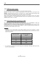
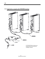
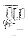
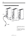
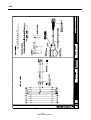
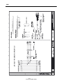
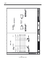
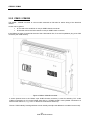
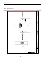
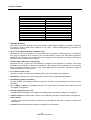
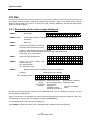
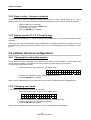
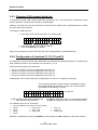
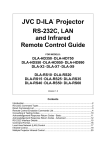
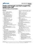
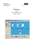
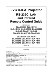
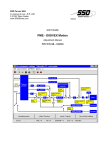
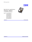
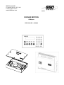
SSD Parvex SAS
8, avenue du Lac - B.P. 249
F-21007 Dijon Cedex
www.SSDdrives.com
DIGIVEX MOTION
CANopen
PVD 3518 GB – 01/2004
PRODUCT RANGE
1-
« BRUSHLESS » SERVODRIVES
TORQUE OR POWER
RANGES
•
•
•
2-
BRUSHLESS SERVOMOTORS, LOW INERTIA, WITH RESOLVER
Very high torque/inertia ratio (high dynamic performance machinery):
⇒ NX -HX - HXA
⇒ NX - LX
High rotor inertia for better inertia load matching:
⇒ HS - LS
Varied geometrical choice :
⇒ short motors range HS - LS
⇒ or small diameter motors : HD, LD
Voltages to suit different mains supplies :
⇒ 230V
three-phase for «série L - NX»
⇒ 400V, 460V three-phase for «série H - NX»
"DIGIVEX DRIVE" DIGITAL SERVOAMPLIFIERS
⇒ SINGLE-AXIS
DSD
⇒ COMPACT SINGLE-AXIS
DµD, DLD
⇒ POWER SINGLE-AXIS
DPD
⇒ MULTIPLE-AXIS
DMD
"PARVEX MOTION EXPLORER" ADJUSTING SOFTWARE
1 to 320 N.m
0,45 to 64 N.m
3,3 to 31 N.m
3,3 to 31 N.m
9 to 100 N.m
SPINDLE DRIVES
•
•
3-
SPINDLE SYNCHRONOUS MOTORS
⇒ "HV" COMPACT SERIES
⇒ "HW" ELECTROSPINDLE,frameless, water-cooled motor
From 5 to 110 kW
up to 60,000 rpm
"DIGIVEX" DIGITAL SERVOAMPLIFIERS
DC SERVODRIVES
•
•
•
4-
"AXEM", "RS" SERIES SERVOMOTORS
"RTS" SERVOAMPLIFIERS
"RTE" SERVOAMPLIFIERS for DC motors + resolver giving position
measurement
0.08 to 13 N.m
SPECIAL ADAPTATION SERVODRIVES
•
•
5-
"EX" SERVOMOTORS for explosive atmosphere
"AXL" COMPACT SERIES SERVOREDUCERS
POSITIONING SYSTEMS
•
•
•
•
Numerical Controls « CYBER 4000 » 1 to 4 axes
"CYBER 2000" NC 1 to 2 axes
VARIABLE SPEED DRIVE - POSITIONER
⇒ SINGLE-AXIS
DSM
⇒ POWER SINGLE-AXIS
DPM
⇒ MULTIPLE-AXIS
DMM
ADJUSTMENT AND PROGRAMMING SOFTWARE PARVEX MOTION EXPLORER
5 to 700 N.m
DIGIVEX MOTION - CANopen
Contents
1.
CAN
1-1
1.1 Introduction
1.2 Electrical Connections
1.2.1
Connector description
1.2.2
CAN bus power supply
1.2.3
Connecting devices operating on CAN
1.2.4
CAN Cable characteristics
1.3 Connecting for drives setting
1.3.1
General points
1.3.2
Application example with CRS232B interface
1.3.3
Application example with CIM03B interface
1.3.4
Application example with RS232CAN interface
1.4 CANopen characteristics
1.5 Cables connecting Diagrams
2.
CRS232 / CIM03
2-1
2.1 Introduction
2.2 Physical Presentation
2.2.1
CRS232 / CRS232B
2.2.2
CIM03 / CIM03B
2.3 Dimensions
2.4 RS232 connector
2.5 CRS232 and CIM03 Technical Characteristics
3.
1-1
1-1
1-1
1-2
1-2
1-3
1-3
1-3
1-4
1-5
1-6
1-7
1-7
µVISION TERMINAL
2-1
2-1
2-1
2-2
2-3
2-5
2-5
3-1
3.1 Introduction
3.2 Description
3.3 Dimensions
3.4 Technical Characteristics
3.5 Use
3.5.1
Description of the various pages displayed
3.5.2
Enter a value - Answer a question
3.5.3
How to use the F1, F2, F3 and F4 keys
3.6 µVision terminal configuration
3.6.1
Changing the subscriber number
3.6.2
Changing user name
3.6.3
Changing CAN network baud rate
1
PVD 3518 GB 01/2004
3-1
3-1
3-3
3-3
3-5
3-5
3-6
3-6
3-6
3-6
3-6
3-7
DIGIVEX MOTION - CANopen
3.6.4
3.6.5
Configuration of functions F1, F2, F3 and F4
CANopen norm
3-7
3-8
Characteristics and dimensions subject to change without notice.
YOUR LOCAL CORRESPONDENT
SSD Parvex SAS
8 Avenue du Lac / B.P 249 / F-21007 Dijon Cedex
Tél. : +33 (0)3 80 42 41 40 / Fax : +33 (0)3 80 42 41 23
www.SSDdrives.com
Available DIGIVEX MOTION instructions
♦
♦
♦
♦
♦
♦
♦
♦
♦
♦
♦
♦
♦
♦
♦
DIGIVEX Single Motion (DSM) User Manual
DIGIVEX Power Motion (DPM) User Manual
DIGIVEX Multi Motion (DMM) User Manual
DIGIVEX Motion - CANopen
DIGIVEX Motion - Profibus
PME-DIGIVEX Motion Adjustment Manual
DIGIVEX Motion Directory of Variables
DIGIVEX Motion Programming
DIGIVEX Motion - Cam Function
PME Tool kit User and Commissioning Manual
CANopen - CAN Bus Access via CIM03
CANopen - Remote control using PDO messages
"Block Positioning" Application Software
"Fly shear linear cutting" software application
"Rotary blade cutting" software application
(DSM)
(DPM)
(DMM)
2
PVD 3518 GB 01/2004
PVD3515
PVD3522
PVD3523
PVD3518
PVD3554
PVD3516
PVD3527
PVD3517
PVD3538
PVD3528
PVD3533
PVD3543
PVD3519
PVD3531
PVD3532
CAN
1. CAN
1.1 Introduction
Data is exchanged between DIGIVEX MOTION CANopen positioners, CRS232 or CIM03
interface boards and µVision terminals via a CAN (Control Area Network) field bus. Reliability
and high speed are the main advantages of this automotive industry serial bus. Information is
encoded by the CANopen protocol.
1.2 Electrical Connections
1.2.1 Connector description
The CAN bus is connected by 9-pin SUB-D connectors (9-pin SUB-D plugs on devices):
PIN
TYPE
FUNCTION
2
CAN-L
7
CAN-H
CAN bus data
transmission
3
0VC
9
24VC
CHARACTERISTICS
Power supply
CAN bus differential signal
CAN bus differential signal
0V (CAN driver 0V and
power supply)
Input or output
1
not used
4
not used
5
NC
Differential pair
not used
6
not used
8
not used
1-1
PVD 3518 GB 01/2004
CAN
1.2.2 CAN bus power supply
The CAN interfaces of each device require a +24 V power supply to operate.
As a rule, this power must be supplied independently of the various devices connected to the
network.
However, DIGIVEX MOTION devices can provide a 24 V power supply with short-circuit and
inversion protection. This power supply can provide 100 mA (2.4 W at 24 V).
When several DIGIVEX MOTION devices are connected to the CAN bus, their +24 V power
supplies are added (e.g. if two DIGIVEX MOTION devices are connected to the bus, the power
available will be 2.4 W x 2 = 4.8 W).
1.2.3 Connecting devices operating on CAN
The various devices on the CAN network are hooked up 2 by 2 by a DIG05982R1-- cable (see
drawing FELX 305981) with two connectors (plug and socket) at each end.
A 120 Ω resistor is to be inserted at each end of the line. This may be done either through a CAN
DIG05984R100 terminal (see drawing FELX 305983), or, where a CRS232 module is the line end,
by setting the module adapter switch to ON.
Comments :
depending on the overall length of the network (between the two end resistors), a certain
transmission speed must not be exceeded. (See the separate device instructions for how to
adjust the baud rate).
Baud rate (kbaud)
Maximum length (m)
main line
•
1000
25
500
100
250
250
125
500
50
1000
20
2500
10
5000
As a general rule, drifts from the main string are not authorised. Although, drifts that are less
than 1m can be tolerated.
1-2
PVD 3518 GB 01/2004
CAN
main line
A
120 Ω
B
tap-off
C
D
120 Ω
< 1m
E
1.2.4 CAN Cable characteristics
The CAN cable is a particular type of cable:
• General shielding is connected to the metal-plated Sub-D connector cover.
• 1 twisted pair for +24V power supply (0.5mm2 conductors, 20°C ≤ 40.7 Ω/km linear
resistance).
• 1 twisted pair for the signal (0.15mm2 conductors, 20°C ≤ 143 Ω/km linear resistance,
120 Ω ± 10% at 1 MHz impedance, 62pF/m at 1 MHz capacity between conductors).
The above wiring characteristics must be respected in full to avoid communication
problems.
1.3 Connecting for drives setting
1.3.1 General points
To set a DIGIVEX Motion drive from a PC using PME software, it is necessary to use one of the
following interfaces :
REFERENCE
CRS232B
CIM03B
RS232CAN
DESIGNATION
RS232-CANopen Interfaces
RS232 interface can communicate with one drive at a time
Caution! It is only possible to use this interface if the drive is not
connected to CAN network
(the drive mustn’t use CAN bus to communicate with another drive or
another device)
1-3
PVD 3518 GB 01/2004
CAN
1.3.2 Application example with CRS232B interface
PC/DIGIVEX Motion dialogue is
possible with all the drives via
CANopen network.
1-4
PVD 3518 GB 01/2004
CAN
1.3.3 Application example with CIM03B interface
PC/DIGIVEX Motion dialogue is
possible with all the drives via
CANopen network.
1-5
PVD 3518 GB 01/2004
CAN
1.3.4 Application example with RS232CAN interface
(the drive mustn’t be connected to PROFIBUS network)
PC/DIGIVEX Motion dialogue is
only possible with one drive at a
time.
The drive mustn’t use CAN bus to
communicate with another drive
or
another
device
when
RS232PRO is used.
1-6
PVD 3518 GB 01/2004
CAN
1.4 CANopen characteristics
NMT
Error Control
Node ID
No. of PDOs
PDO Modes
PDO Linking
PDO Mapping
No. of SDOs
Emergency Message
CANopen Version
Framework
Device Profile
Certified
Slave
Node Guarding
HW Switch
4 Rx
4 Tx
Sync (cyclic)
No
Variable
4 Server
1 Client
Yes
DS-301 V4.0
No
DSP-402 V1.1
No
• NMT [Master/Slave]: Describes the role of an appliance within the network. A NMT Master appliance is
capable of initializing the network, whilst a NMT Slave appliance is not. NMT = Network Management (a
procedure for managing the network).
• Error Control [Node Guarding / Heartbeat / No]: Describes the control mechanism for errors tolerated
by the appliance. Node Guarding is a mechanism that, given an appliance which fulfils the role of a NMT
Master, monitors the NMT Slave appliances. Heartbeat is a mechanism that cyclically transmits
messages via the appliance in question, indicating its presence to other members of the network.
• Node ID [LMT / HW Switch / Proprietary]: Describes the way in which the CAN identifier is assigned to
the appliance in question. HW Switch indicates that the identifier is assigned mechanically. LMT
indicates that the identifier can be assigned using a message procedure known as LMT (Layer
Management). Proprietary indicates a method of assignation different from the first two.
• No. of PDOs [n RX / m Tx]: Indicates how many receiving and transmitting PDOs can be managed by
the appliance.
• PDO Modes: Indicates which PDO transmission modes can be managed by the appliance.
• PDO Mapping [Default / Variable]: Indicates whether the appliance accepts a change in the data to be
transmitted to the inside of PDO messages.
• No. of SDOs [n Server / m Client]: Indicates how many Client and Server SDO channels can be
managed by the appliance.
• Emergency Message [Yes / No]: Indicates whether the appliance is capable of managing EMCY
messages (emergency messages).
• CANopen Version: Indicates which version of the CANopen procedure is implemented in the appliance.
• Device Profile: Indicates which CANopen standard is respected by the appliance (DSP 402 = Speed
Controllers and Positioners).
• Certified: Indicates whether the appliance is certified (CiA Certification).
1.5 Cables connecting Diagrams
1-7
PVD 3518 GB 01/2004
CAN
1-8
PVD 3518 GB 01/2004
CAN
1-9
PVD 3518 GB 01/2004
CAN
1-10
PVD 3518 GB 01/2004
CAN
1-11
PVD 3518 GB 01/2004
CAN
1-12
PVD 3518 GB 01/2004
CAN
1-13
PVD 3518 GB 01/2004
CRS232 / CIM03
2. CRS232 / CIM03
2.1 Introduction
CRS232 or CIM03 interface boards are used for connecting a PC to a CAN network via an
RS232 serial link in order to set DIGIVEX MOTION CANopen positioner module parameters.
It is possible to carry out remote reinitialization for the CRS232B and CIM03B versions of these
interfaces (use of Parvex Motion Explorer software is required).
2.2 Physical Presentation
2.2.1 CRS232 / CRS232B
The CRS232/CRS232B converter is a box unit.
• One side provides access to the serial link via a 9-pin SUB-D socket,
• The other side provides access to the CAN network via a 9-pin SUB-D plug.
A switch (next to the CAN 9-pin SUB-D plug) allows the line to be adapted to 120 Ω depending on
the other nodes in the network (see CAN section).
A green LED (next to the 9-pin SUB-D socket) indicates the status of the power supply to the
board.
Figure 1: CRS232/CRS232B board in its housing
2-1
PVD 3518 GB 01/2004
CRS232 / CIM03
2.2.2 CIM03 / CIM03B
The CIM03 / CIM03B converter is a box module mounted on DIN rails for easier wiring of the electrical
cabinet.
Access can be gained:
• at one end to the serial link via a 9-pin SUB-D female connector
• at the other end to the CAN network via a 9-pin SUB-D male connector
If the CIM03 converter is located at the end of the CAN network line, fit a 120 Ω impedance plug to its CAN
connector (see CAN Section).
Figure 2: CIM03 / CIM03B converter
A switch (located next to the RS232 9-pin SUB-D female connector) is used for selecting "PC" mode
(CIM03 connected to a PC via the RS232 serial link) or "STAND ALONE" mode (CIM03 connected to a
terminal other than a PC, e.g. a PLC or electronic board with a serial link).
The two "CAN indentify" rotating switches are not actually used (the set address is not taken into account).
2-2
PVD 3518 GB 01/2004
CRS232 / CIM03
2.3 Dimensions
2-3
PVD 3518 GB 01/2004
CRS232 / CIM03
2-4
PVD 3518 GB 01/2004
CRS232 / CIM03
2.4 RS232 connector
DIGIVEX
INTERNAL
LINKS
DIGIVEX 9-PIN SUB-D
CONNECTOR
1
2
3
4
5
6
7
8
9
TD (TXD)
RD (RXD)
0V
PC 9-PIN SUB-D
CONNECTOR
PC
DCD
RD (RXD)
TD (TXD)
DTR
0V
DSR
RTS
CTS
Ring Indicator
1
2
3
4
5
6
7
8
9
The connector body is earthed. Use a serial extension cable (non-crossed RD and TD) maximum
length 5 m.
Only TD, RD and 0V signal wiring is compulsory with PME DIGIVEX MOTION software.
2.5 CRS232 and CIM03 Technical Characteristics
Power Supply
Typical CAN supply voltage
Min. CAN supply voltage
Max. CAN supply voltage
Typical consumption
2-5
PVD 3518 GB 01/2004
24
20
28
1,6
VDC
VDC
VDC
W
µVision terminal
3. µVISION TERMINAL
3.1 Introduction
The DTP02 µVision terminal is designed for use with one or more DIGIVEX Motion CANopen
positioners for entering application-related values or viewing error messages. The µVision terminal
connects up to the positioner(s) via a CAN link.
IMPORTANT: Before using the µVision terminal you first have to enter parameters for:
• Its number and its CAN subscriber number (§3.6.1 and §3.6.2)
• Its CAN transmission speed (§3.6.3)
• Commands associated with F1, F2, F3 and F4 keys (§3.6.4)
This data must be entered before the µVision terminal is put into service. The data is then stored
in EEPROM memory.
3.2 Description
3-1
PVD 3518 GB 01/2004
µVision terminal
* FASTENING:
The µVision terminal may be hand-held or screw mounted (e.g. to an electrical cabinet door) (cf.
dimensional drawing).
* SCREEN:
2 lines of 16 characters
* 22 KEY KEYBOARD:
Because the µVision terminal is made from thermoformed plastic, the keys should not be pressed
with sharp instruments such as screwdrivers.
Keys:
SHIFT
allows access to user-defined functions F1, F2, F3 & F4. A red LED shows
whether the Shift key is activated. It is deactivated after any key is pressed
and acknowledged.
START
validates (command for all connected positioners)
Function currently unavailable.
STOP
interrupts (command for all connected positioners)
Function currently unavailable.
YES
positive answer to a prompt (returns digit 1)
NO
negative answer to a prompt (returns digit 0)
Ï
Select the previous page
Ð
Select the following page
PAGE
selects a page from 0 to 9 for display
Í
erases the character before the cursor
+/-
enables the user to key in negative values
ENTER
validates a numerical value or YES/NO answer keyed in
0..9, .
number pad for entering numerical values
3-2
PVD 3518 GB 01/2004
µVision terminal
3.3 Dimensions
3.4 Technical Characteristics
CAN bus connector
Electrical connections
CAN baud rate
CAN bus (ISO/DIS 11898)
9-pin SUB-D plug
See CAN section
10, 20, 50, 125, 250, 500, 1000
(can be modified via µVision terminal)
Kbauds
Power Supply
Typical CAN supply voltage
Min. CAN supply voltage
Max. CAN supply voltage
Typical consumption
24
20
28
1
3-3
PVD 3518 GB 01/2004
VDC
VDC
VDC
W
µVision terminal
CANopen
NMT
Error Control
Node ID
No. of PDOs
PDO Modes
PDO Linking
PDO Mapping
No. of SDOs
Emergency Message
CANopen Version
Framework
Device Profile
Certified
Slave
No
Proprietary
0 Rx
0 Tx
No
No
No
1 Server
1 Client
No
DS-301 V4.0
No
DSP-403 V1.0
No
• NMT [Master/Slave]:
Describes the role of an appliance within the network. A NMT Master appliance is capable of initializing
the network, whilst a NMT Slave appliance is not. NMT = Network Management (a procedure for
managing the network).
• Error Control [Node Guarding / Heartbeat / No]:
Describes the control mechanism for errors tolerated by the appliance. Node Guarding is a mechanism
that, given an appliance which fulfils the role of a NMT Master, monitors the NMT Slave appliances.
Heartbeat is a mechanism that cyclically transmits messages via the appliance in question, indicating its
presence to other members of the network.
• Node ID [LMT / HW Switch / Proprietary]:
Describes the way in which the CAN identifier is assigned to the appliance in question. HW Switch
indicates that the identifier is assigned mechanically. LMT indicates that the identifier can be assigned
using a message procedure known as LMT (Layer Management). Proprietary indicates a method of
assignation different from the first two.
• No. of PDOs [n RX / m Tx]:
Indicates how many receiving and transmitting PDOs can be managed by the appliance.
• PDO Modes: Indicates which PDO transmission modes can be managed by the appliance.
• PDO Mapping [Default / Variable]:
Indicates whether the appliance accepts a change in the data to be transmitted to the inside of PDO
messages.
• No. of SDOs [n Server / m Client]: Indicates how many Client and Server SDO channels can be
managed by the appliance.
• Emergency Message [Yes / No]:
Indicates whether the appliance is capable of managing EMCY messages (emergency messages).
• CANopen Version: Indicates which version of the CANopen procedure is implemented in the appliance.
• Device Profile:
Indicates which CANopen standard is respected by the appliance (DSP 402 = Speed Controllers and
Positioners).
• Certified: Indicates whether the appliance is certified (CiA Certification).
3-4
PVD 3518 GB 01/2004
µVision terminal
3.5 Use
The µVision terminal provides access to ten separate pages (page 0 - page 9). The page number selected
flashes at the top right of the screen. To access any page, press the PAGE key and then the desired page
number or the Ï or Ð keys.
3.5.1 Description of the various pages displayed
* PAGE 0 :
Home page
D I
G I
P A R V E X
V E X
µ V i
0
s i
o n
* PAGES 1,2,3,4 :
These pages contain a visual display of messages sent by variable speed drive
positioners.
* PAGE 5 :
Reserved.
* PAGE 6 :
Shows the CAN address, CAN baud
rate and µVision terminal user name
I d : 1 6
B R :
U s e r n a m e
1 0 0 0
6
Address : CAN network subscriber number (Id)
Baud rate: CAN network transmission speed in kbaud (BR: Baud Rate)
User name: up to 15 characters
* PAGE 7 :
Shows the total operating time
* PAGE 8 :
Shows the serial number
software version
SN : Serial Number
SV : Software Version
* PAGE 9 :
R U N N I N G
T I
0 0 0 0 6 : 2 7 :
and
S N :
S V :
M E
4 3
7
9 9 1 0 0 0 1
A P 7 5 2 V 0 1
8
Displays the last 32 fault messages sent over the CAN bus.
Example:
Message date (time display)
↓
Error message number→ E R R 0 1
0 0 3 6 9 : 1
d 0 1
0 5
4 0 0 0 h
↑
↑
CAN subscriber nature of the error if
having
the subscriber having
generated the generated the
message
message is a
PARVEX variable
speed drive positioner
7
9
↑
Error nature following
CANopen norm
(see §3.6.5 CANopen
norm)
The last 32 fault messages are memorized in the EEPROM store. They are displayed on page 9. The last
fault message is displayed first.
When a new fault is to be displayed, the read-out switches automatically to page 9 to display the fault. The
message flashes and the user must validate by pressing the ENTER key.
The time displayed is µVision terminal operating time.
Press ENTER to obtain the meaning of the message being visualized in clear text (English).
3-5
PVD 3518 GB 01/2004
µVision terminal
3.5.2 Enter a value - Answer a question
A positioner may request an application-related value (number of parts, cutting length, etc.) or ask a
question of the user. The µVision terminal then switches automatically to the page (1-4) with the question:
• Display question from positioner
• Answer with number pad or YES/NO keys
(use the Í key to correct).
• Press the ENTER key to validate.
3.5.3 How to use the F1, F2, F3 and F4 keys
The F1, F2, F3 and F4 keys are active providing that the SHIFT key was previously selected (red LED
activated).
These keys are used to send predetermined messages to the variable speed drive positioners present on
the CANopen bus (previously selected variable set to 1 or to 0, see configuration of F1 to F4 keys in section
§3.6.4).
3.6 µVision terminal configuration
3.6.1 Changing the subscriber number
An identification number is allocated to the µVision terminal when it is first installed in a CAN network. This
number must be between 1 and 63 and must not be used by any other device on the network.
To change the identification number:
• Press keys 8 and 2 at the same time. The display reads :
I d .
N E W
N o d e
?
:
0 3
• Enter the new subscriber number (use the Í key to correct).
• Press the ENTER key to validate.
Page 6 is then displayed with the new subscriber number which is safeguarded in the EEPROM store.
3.6.2 Changing user name
A user name can be specified for the µVision terminal.
• Press keys 8 and 1 at the same time. The display reads :
U S E R N A M E
U s e r n a m e
?
• The Ï and Ð keys scroll through the characters beneath the cursor.
• The Í and +/- keys move the cursor horizontally.
• Press the ENTER key to validate
Page 6 is then displayed with the new user name which is safeguarded in the EEPROM.
3-6
PVD 3518 GB 01/2004
µVision terminal
3.6.3 Changing CAN network baud rate
To dialogue with other CAN network subscribers (positioners, etc.), the CAN network transmission speed
must be specified. The baud rate is limited by network length.
Attention! The baud rate must be the same for all network users. Default value: 1000 kbauds (do not modify
this value without good reason).
To change the CAN baud rate :
• Press keys 8 and 0 at the same time. The display reads:
C A N
B a u d r
1 0 0 0
a t
e
?
K b a u d
• Select the baud rate with the Ï and Ð keys
• Press the ENTER key to validate.
Page 6 is then displayed with the new baud rate which is safeguarded in the EEPROM store.
3.6.4 Configuration of functions F1, F2, F3 and F4
The selecting of functions F1, F2, F3 or F4 enables a predetermined variable belonging to a variable speed
drive positioner present on the CANopen bus to be set to 1 or to 0.
Press the following keys at the same time:
•
•
•
•
9 and 1 are used to access the configuration for function F1
9 and 2 are used to access the configuration for function F2
9 and 3 are used to access the configuration for function F3
9 and 4 are used to access the configuration for function F4
Pressing keys 9 and 1 at the same time (configuration for function F1), displays the following:
I
d
:
The numerical keyboard is used to edit the CAN identifier value of
the variable speed drive positioner to which the command will be
transmitted (use the Í key to correct)
↓
0 1
F 1 ← function F1
e x e c _ e n
= 1
↑
the Ï and Ð keys are used to determine the
order (variable name selection)
↑
the YES key assigns the value 1 to the selected variable
the NO key assigns the value 0 to the selected variable
The variables which we can choose are:
• none (A support on the touch F1 has no effect)
• ub100
• home_cmd
• ub101
• abort_cmd
• ub102
• reset_cmd
• ub103
•
•
•
exec_en
move_en
torque_cmd
Selection is validated by pressing the ENTER key and pressing the YES or NO key confirms the selection.
3-7
PVD 3518 GB 01/2004
µVision terminal
3.6.5 CANopen norm
CANopen variable speed drive positioner error message
codes
DIGIVEX
variable
CANopen
error
speed drive
positioner message
code
status_
number
3
4
5
7300h
4110h
4000h
6
2000h
7
8
9
10
11
8400h
2000h
2000h
2000h
2000h
12
2000h
13
2000h
14
2000h
15
16
17
18
19
20
22
23
24
25
26
27
28
29
30
31
32
33
34
35
37
38
41
42
3000h
4210h
6320h
8100h
7120h
5500h
5000h
6320h
6320h
8612h
8612h
6200h
8611h
5000h
1000h
5300h
5300h
8612h
8612h
8400h
7300h
9000h
8000h
6320h
Generic error message codes for all
CANopen subscribers
Description
Resolver failure
Excessive ambient temperature
Excessive heatsink temperature
High heatsink temperature with reduced
current
Excessive motor speed (in rpm)
Excessive supply current
Excessive variable speed drive current
Excessive dI/dt
Excessive average current
Excessive average current with reduced
current
Excessive RMS current
Excessive RMS current with reduced
current
Bus overvoltage
Excessive motor temperature
Incompatible Axis/Spindle definition
CAN link fault
Motor not connected
User program memory fault
Personalization board missing
Axis / personalization board incompatible
Internal parameter calculation fault
+ Electrical limit reached
- Electrical limit reached
Program execution fault
Tracking error fault
Option card fault
Generic error
C167 CPU Fault
DSP CPU Fault
+ Software limit reached
- Software limit reached
Excessive application speed (in Units/s)
Encoder fault
Emergency stop
Synchronization message timeout
Licence missing
3-8
PVD 3518 GB 01/2004
Description
00xxh Error Reset or No Error
10xxh Generic Error
20xxh Current
21xxh
Current, device input side
22xxh
Current inside the device
23xxh
Current, device output side
30xxh Voltage
31xxh
Mains Voltage
32xxh
Voltage inside the device
33xxh
Output voltage
40xxh Temperature
41xxh
42xxh
50xxh
60xxh
61xxh
62xxh
63xxh
70xxh
80xxh
81xxh
90xxh
F0xxh
FFxxh
Ambient Temperature
Device Temperature
Device Hardware
Device Software
Internal Software
User Software
Data Set
Additional Modules
Monitoring
Communiocation
External Error
Additional Functions
Device specific