1
VII. POLYSOMNOGRAPHY PROTOCOL
A. Environment and Equipment Requirements
1. Equipment
2. Recording Methods
3. Environment VII-4
VII-4
VII-4
B. Parental Education
VII-5
C. Scheduling
1.
2.
3.
4.
Healthy Term Infants
Apnea of Infancy Infants
Premature Infants
Sibling of SIDS
VII-7
VII-7
VII-7
VII-7
D. General PSG Procedures
1.
2.
3.
4.
5.
6.
7.
8.
9.
10.
11.
12.
13.
14.
15.
16.
VII-7
Preparation of Laboratory
Duration of Monitoring
Staffing
Procedures Prior to PSG
a. CHIME PSG Thermometer Preparation
ALICE 3: Procedure For Data Collection
Polygraphic Recording Preparation
Application of Electrodes
a. ECG
b. Respiration Effort
c. Temperature
d. EEG
e. Submental EMG
f. Pulse Oximeter (SaO2)
g. Position Sensor
h. PETCO2
i. Thermistor
j. Actimeter
k. LEOG/REOG
CHIME Monitor Signal Evaluation
Connecting the Infant to "Calvin"
Positioning Infant
Environmental Conditions
Assessing Signal Quality
Test Signal Transfer to DAS
Synchronization of Time Clocks
Calibration
Chart Annotation
ςΙΙ−1
VII-7
VII-7
VII-7
VII-8
VII-8
VII-11
VII-12
VII-13
VII-13
VII-16
VII-16
VII-16
VII-19
VII-23
VII-23
VII-23
VII-23
VII-23
VII-23
VII-27
VII-28
VII-30
VII-30
VII-30
VII-31
VII-32
VII-33
VII-33
10/02/95
17.
18.
19.
20.
21.
22.
23.
Guidelines for Re-Application of Electrodes
Nurse/Technician/Caretaker Interventions
Adjustments of Waveforms During PSG Recordings
Termination of Monitoring
Site Assessment of PSG Quality
DCAC Assessment of PSG Quality
Cry Recording
E. Protocol for Emergency Intervention during PSG
VII-34
VII-38
VII-38
VII-38
VII-39
VII-40
VII-41
VII-42
F. PSG Scoring
1. Introduction to Scoring
2. Procedures
step 1 QUALITY CONTROL
step 2 INITIAL SURVEY AND DCAC COMMUNICATIONS
step 3 INITIAL ALICE REPORT
step 4 Sleep Wake State Scoring
step 5 Transient Arousal Scoring Rules and Procedure
step 6 Score Apnea Events ≥ 10 Seconds
step 7 Scoring of Hypopnea
step 8 Artifact removal
1.) SaO2
2.) CO2
3.) ECG
step 9 Final Report
ALICE
step 10 Comparison of ALICE 3 and CHIME Monitor events
Appendix A
VII-43
VII-43
VII-43
VII-44
VII-45
VII-45
VII-51
VII-53
VII-60
VII-62
VII-63
VII-63
Appendix C
CHIME PSG Data Acquisition System
Eye Movement Sensor
CHIME PSG Thermometer
Table of Contents
CHIME Monitor PSG Cartridge Parameters
Quality of Individual PSG Channels
Forms F1
Example of Instructions to Parents
State Coding Parameter Summary (5/1/95)
ALICE 3 Waveform Scoring Examples
DCAC PSG Quality Review Form
References
Reprint: EEG Arousals Scoring Rules and Examples
VII-65
VII-67
VII-68
VII-71
VII-74
VII-75
VII-77
VII-82
VII-84
VII-85
VII-117
VII-118
VII-119
Appendix D
Approved Sensor List
VII-125
Appendix B
ςΙΙ−2
10/02/95
List of Tables and Figures
Tables
1.PSG Montage
VII-5
2.Infant Sleep Lab VII-6
3.PSG Preparation and Acquisition Checklist
4.Electrodes and Supplies Required
5A.Items to be Entered on ALICE3/F1
5B.Infant Behaviors Annotation
6.Codes to States VII-49
VII-9
VII-13
VII-35
VII-36
Figures
1.Electrode placement: Respiband placement
2.Connecting Respiband to Patient Cable
3.Standard International 10-20 Scalp Electrode Placement Sites
4.EOG and EMG Electrode Placement
5.Head Wrap Illustration
6.Pulse Oximeter Placement
7.Calvin Input Device
8.Healthdyne Thermistor Placement
9.Healthdyne Patient Box Inputs
10.Respiration Rate in ALICE3
11.Events Table
ςΙΙ−3
VII-14
VII-14
VII-18
VII-21
VII-22
VII-24
VII-25
VII-26
VII-28
VII-48
VII-56
10/02/95
A. Environment and Equipment Requirements
1.
Equipment
A Healthdyne ALICE 3 system (currently version 1.17) will be used for the laboratory
polysomnographic recordings. The basic reference is the ALICE 3 System Software User's
Manual (Adult/Infant Acquisitions) 1994 edition. This system which consists of a 486/33 IBM
computer and 20" monitor also includes (a) a HP LaserJet IIIP Printer, (b) an 800 mB optical
disk drive and one or more disk drives (such as a 3.5" high density floppy disk drive). ALICE 3
requires interfacing with an amplifier/signal processor unit (CALVIN) and special input device.
It includes infant software to analyze cardiorespiratory, EEG, and sleep state data.
In order to raise sampling rates and allow for adequate storage, an additional 486 computer
(Gateway 2000), referred to as the Data Analysis System (DAS) will be interfaced with ALICE
3. The DAS will use 12 bit storage rather than the 8 bits used by ALICE 3. See Appendix A.
2.
Recording Methods
The montage to be used for the CHIME study is listed in Table 1.
Since this is a research protocol and the data are to be analyzed by computer, the montage as
specified must be used under all circumstances. Changes should only be made under
exceptional circumstances and should be noted on the chart/log and in the ALICE 3 initial
screen or subsequent comment section.
To complete the monitoring montage, the ALICE 3 system will be interfaced with the CHIME
Monitor and a monitor that produces an end-tidal PCO2 output. Audio/video monitoring
equipment also must be used during the sleep study.
3.
Environment
The laboratory should consist of two adjacent rooms, one for the sleeping infant and one for
the equipment. The parent or caregiver will be instructed not to interfere with the infant during
the study, but may sleep in a nearby bed. During sleep a 40W light should be on in the infant
sleeping room to permit continuous surveillance through a TV monitor/VCR system.
Sophisticated split-screen monitors are optimal but not required. See item list in Table 2.
Access from the equipment room to the infant sleeping room should be easy in case of
emergency. The infant sleeping room should have resuscitation equipment and tray in case
this is needed as well as a system for alerting support personnel. A sink, a scale and other
routinely used equipment should be handy. Carpeting is desirable so that arousals are
minimized, but anti-static treatment should be considered. Overhead fluorescent lights may
introduce artifacts and should not be used during monitoring. Room temperature control is
desirable but not always available.
The sleeping room is used for infant preparation. Infants must sleep in a crib with sides that
can be lowered easily.
ςΙΙ−4
10/02/95
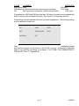
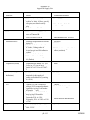
TABLE 1: PSG MONTAGE
Channels
1
R EOG
12
Impedance
2
L EOG
13
Rib Cage
3
C4 - M1
14
Abdomen
4
C3 - M2
15
Sum
5
O2 - M1
16
CO2
6
O1 - M2
17
CO2 Number
7
Chin
18
Thermistor
8
Position
19
Oximeter Pulse Waveform
9
Temp
20
O2 Saturation
10
ECG
21
Actimeter (ALICE 3)
11
Cardiotachometer
*If not used, blank out the channel by inserting jumper cables in the appropriate inputs of the ALICE
3 input device. DO NOT change/rearrange the number order/position of the channels.
B. Parental Education
As part of the PSG consent process, study personnel will visit with the parent(s)/caregiver(s) of
the study infant to discuss the purpose of the PSG and what can be expected in the laboratory.
A photograph album is typically used to illustrate procedures; questions are encouraged. Easy
to read handouts in the appropriate language should be made available for parents and
caregivers. These handouts should contain information about where the PSG is to be
conducted, what the parents need to bring and when they need to bring the baby. See
Appendix B for an instruction sheet example.
ςΙΙ−5
10/02/95
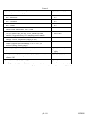
TABLE 2
INFANT SLEEP LAB
LIGHTING
1. Preparation Stage - Standard Overhead Lighting
2. Monitoring Stage - 40 W Adjustable Lamp
TEMPERATURE
1. Ambient 23OC
BED
1. Infant Crib
INFANT SUPPLIES
1.
2.
3.
4.
5.
6.
7.
Diapers
Shirts
Blankets
Pacifiers
Suction Bulb
Formula/Breast Milk
1 Piece Sleeper
ASSOCIATED EQUIPMENT
1.
2.
3.
4.
Sink
Scale
O2
Suction
INFANT SLEEP ROOM
1.
2.
3.
4.
Video Camera
CO2 Monitor
CHIME Monitor
Carpeting
EQUIPMENT MONITORING ROOM
1. ALICE 3 Monitoring System
2. Video Monitor Recorder
3. Telephone
CHIME BACKUP MONITOR
EMERGENCY CART/TRAY
ςΙΙ−6
10/02/95
C. Scheduling
1.
Healthy Term Infants
When a Healthy Term infant is enrolled, the DCAC will inform the site at what age to perform a
PSG.
2.
Apnea of Infancy Infants
Apnea of Infancy subjects should be scheduled within two weeks of study intake.
3.
Preterm Infants
Preterm infants should be scheduled to have a PSG within two weeks of study intake.
4.
Siblings of SIDS Infants
Subsequent siblings should be scheduled to have a PSG at 1 month of age. Surviving twins of
SIDS victims receive a PSG which should be scheduled as soon as possible after the death of
their twin.
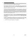
D. General PSG Procedures
1.
Preparation of the Laboratory
It is critical that the laboratory is surveyed at the completion of a recording and prepared for the
next recording. The polysomnographic equipment should be left in good operating condition.
Monitoring personnel should maintain an equipment log (See example in Appendix B) so that
engineers can identify problems encountered during the night when they are not typically
available. Several hours prior to the next monitoring session the laboratory should again be
checked, preferably by technical personnel and all equipment prepared, tested and settings
verified.
For sites where PSG staff initializes CHIME Monitor cartridges, see CHIME Monitor PSG
cartridge parameters in Appendix B. At other sites CHIME staff will provide prepared PSG and
new home cartridges for each PSG.
2.
Duration of Monitoring
Physiological monitoring should begin prior to 9pm when all infant preparation and calibrations
have been completed. One and a half hours for these preparatory tasks is realistic.
Recordings should be terminated after no less than 8 hours of recording, followed by calibration
and preparation of infants for departure.
3.
Staffing
Infants should be under continuous observation of trained personnel in sufficient numbers to
observe the baby and properly annotate the study. When considering staff requirements, one
should take into account the need to continue annotation while the infant is awake and cared
for as well as staff fatigue. Funds for two staff were budgeted.
ςΙΙ−7
10/02/95
4.
Procedures Prior to Polysomnography
It is important that arrival time in the hospital is selected so that parents/caregivers are in a
position to bring the infant (e.g. after working hours) and that the trip is safe (in some settings,
parking and hospital ground escorts may have to be considered).
Each laboratory should have a log book in which details about the infant and the
polysomnographic session can be entered. A loose leaf folder can be designated for each
infant in which all relevant information is contained. The infant's Study ID# is critical because
all information will be filed under this number.
It is important to review procedures with the parents and to offer explanations. Parents can be
invited to watch or hold the child as needed. Much of the skin preparation and attachment of
electrodes can be done while the baby is bottle fed. In some laboratories the mother/caregiver
will be permitted to stay throughout the night but few elect to do so (exceptions are those who
prefer to breast feed the baby). In some laboratories one parent or caregiver is required to stay
with the baby to help with caregiving. A maternal sleeping room should be made available so
that unnecessary awakenings are prevented.
Prior to preparing the study infant for monitoring, the Post-Enrollment Medical Follow-up
Form (Form D) should be completed if one has not been completed in the past 2 weeks. If the
infant has been home on a study monitor, technicians should collect the Alarm Log (Form H5)
from caregivers.
A CHIME POLYSOMNOGRAPHY CHECKLIST (Form F1: See Appendix B) should be initiated
at this time and items completed as the calibrations and sleep study progress. Refer to Table
3, PSG Preparation and Acquisition Checklist, as a reminder of steps to be followed.
a.
CHIME PSG Thermometer preparation. See Appendix A.
ςΙΙ−8
10/02/95
TABLE 3
PSG PREPARATION AND ACQUISITION CHECKLIST
1.
The Begin Study data calibration must begin no later than 2100 hours, therefore, preparation
should commence by 1900-1930 hours. Have baby brought to lab at 1830-1900 hours.
2.
Prior to infant arrival do the following:
a. Lay out all electrodes, supplies, equipment, including extra baby diapers, etc.
b. Have backup CHIME Monitor and CHIME supplies ready.
c. Get out all forms - this checklist, H2-Visit, H5, F1, Channel Checklist, Optical Disk-Log and
Cry Log.
d. Set up Nellcor or CO2 monitor as needed.
e. Have CHIME PSG and home cartridge, as well as the optical disk ready for use.
f. Connect all components to ALICE 3. Turn ALICE3 on and check CO2 range values.
g. Check audio-video equipment, emergency box and notification routine.
h. Prepare other site-specific forms/logs as needed.
I. Synchronize time clocks as needed.
3.
Infant arrival:
a. Collect H-5 from caregiver; do Form D if necessary.
b. Check CHIME Monitor and condition of electrodes.
c. Remove home cartridge out of the CHIME Monitor and replace it with the PSG cartridge.
Do not turn monitor on until baby is quiet and you are ready to check waveforms (5
minutes of quiet recording is required to set monitor baselines).
d. Enter patient information on ALICE3 and estimate begin and end acquisition times.
e. View waveforms and go to calibration to set filters and check impedances. Use jumper
cables to eliminate ECG artifacts if necessary.
f. Adjust and reapply sensors as needed to get impedances < 10K ohms and clean
waveforms. Type final impedances on ALICE3 screen at study initiation.
g. Set end acquisition to allow 8 hours post 2100 plus enough time for post calibration, time
check and Cry if ordered. Remember ALICE3 cannot do more than 10 hours total.
h. It should be no later than 2030 at this point. If all is well, start oximeter time check
process, calibrations and then begin study. Type Begin Study on ALICE3 directly after
end of Calibrations.
I. Enter interventions, feeding, diaper changes, temperature and humidity on Form F1.
j. During PSG recording, annotate all behaviors of the infant and staff which may impact on
the PSG recording. See Section 16, Chart Annotation. Do not forget to comment at least
every 5 minutes, especially during sleep; note eyes closed (EC). DO NOT USE ANY
UNDEFINED ABBREVIATIONS PLEASE.
ςΙΙ−9
10/02/95
END OF STUDY CHECKLIST
1.
If you set the stop acquisition time for, say, 0530 then you must be prepared to do the oximeter
time routine, 1 minute of calibrations and up to 5 minutes (?) for the Cry before 0530.
2.
If Begin Study occurred prior to 2100 hours and you want to end after 8 hours but before the
stop time you entered, you can, but remember to do time check, calibrations, Cry if needed,
and recheck impedances first!
3.
After ALICE 3 is stopped, the file will automatically transfer the data to the optical disk. Note
end temperature and humidity and any observation of infant condition on Form F1.
4.
Turn CHIME Monitor power off and remove PSG-cartridge. Put new home cartridge in monitor.
5.
Remove electrodes, replacing CHIME Monitor sensors if necessary. Prepare baby for return to
nursery or home. Chart or log baby out of Sleep lab.
6.
Put together all forms and cartridges needed for CHIME analysis.
7.
Clean all sensors, equipment as needed.
8.
Back-up optical file as soon as possible, complete back-up optical log and Form F1.
ςΙΙ−10
10/02/95
5.
1.
Verify
that the RJ45
connected between the PC and the Calvin amplifier box. The
ALICE
3 Procedure
forcable
Datais Collection
Calvin box should be plugged into the socket marked "PHONE" on the computer. NEVER PLUG IN
PHONE
JACK ORthe
UNPLUG
IT IF ALICE 3 POWER IS ON.
a. Preparing
Software
After attaching the sensors to the patient, you must provide the ALICE 3 software with
Make sure your computer power is on, and the ALICE 3 System Main Menu is displayed.
information necessary to begin the acquisition. Although the electrode application was
described
be done
prior to
infant
preparation.
3. Select earlier,
the first Step
option5a
onwill
the usually
Main Menu,
Acquisition
and
Analysis,
by pressing the letter "A" or
2.
by clicking on the option with the left mouse button. A list of montages will be displayed.
4. Select the CHIME montage that you will be using for the CHIME study. The screen will display
the message, "Please wait for CALVIN self-check..." The Patient information Screen will be displayed
after the self-check process is complete.
5. Enter the patient's Event Record Label in last name field, first name, date of birth, sex and
gestational age. Press <ENTER> to move from one field to the next (see box below).
6. In comment section enter infant's assigned group, i.e., comparison, SIDS SIB, ALTE, and
impedances.
10/07/93 10:34
Event Record Label :
21 CHARACTERS MAX
First name :
21 CHARACTERS MAX
Date of birth :
12 12 92
Gestational age :
40
NOTE: If you Comments :
continue
to
information
completed all Acquisition start time :
Acquisition stop time :
21 CHARACTERS MAX
21 CHARACTERS MAX
00 00
Sex :
F
make an error,
enter
until you have
fields. You will
06 00
ςΙΙ−11
10/02/95
have an opportunity to correct any mistakes before leaving this screen.
ςΙΙ−12
10/02/95
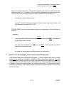
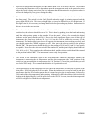
6. Polygraphic recording preparation
The polygraphic recording should contain the information requested on the ALICE 3 screen as
illustrated in 5a.
[ALICE 3 screen at study initiation will
be added here when software is
available on ALICE 3]
ςΙΙ−13
10/02/95
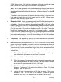
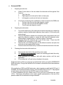
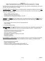
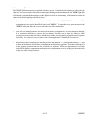
7. Application of Electrodes
Directions are presented in the optimal order of application. Table 4 summarizes the necessary
array of electrodes by placement site. Extra sensors must be available in case last minute
replacements are required. This is particularly important for specialized sensors such as the
Healthdyne thermistor and actimeter. See Appendix D for a listing of approved sensors.
TABLE 4
ELECTRODES AND SUPPLIES REQUIRED
BODY
1.
2.
3.
4.
5.
ECG (5)
Respiratory Bands
Oximeter Probe
Position Sensor from CHIME Monitor (back of diaper)
ALICE 3 Actimeter
HEAD
1. EEG (7)
2. EMG (3)
3. Kerlix Wrap
FACE
1. CO2 Cannula
2. Healthdyne Neonate/Infant Nasal/Oral Thermistor
3. EOG (2)
a.
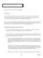
ECG: Ensure that the baby's skin is dry and free of powder, oil or perspiration to
provide for good contact between the sensors and the skin. A total of five ECG
electrodes will be applied: two Jenson hydrogel squares* to interface with the
CHIME monitor and three IttyBitty Contour hydrogels for the ALICE 3 connections.
Be sure to snap the lead wire snaps to the electrodes BEFORE placing the
electrodes on the baby. Peel the electrode off the plastic strip and place as follows:
the sites are illustrated in Figure 1.
ςΙΙ−14
10/02/95
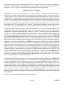
ELECTRODE PLACEMENT RESPIBAND PLACEMENT
CHIME Monitor: B=Black Snap, W=White Snap. During the PSG the red
ground electrode of the CHIME monitor is not used.
ALICE 3: [O] ALICE3; 2 ECG leads; 1 ground (G)
Figure 1
ςΙΙ−15
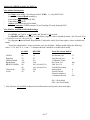
10/02/95
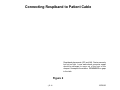
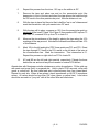
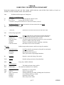
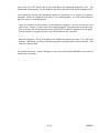
Connecting Respiband to Patient Cable
Respiband placements (RC and AB). Fasten securely
but not too tight. Loose ends where connector snaps
should be arranged to come out of the front of the
sleeper if it snaps at the midline. REMEMBER no gaps
in the tails.
Figure 2
ςΙΙ−16
10/02/95
CHIME Monitor Leads: RA (Right Arm) white snap on the right chest at the nipple
level. LA (Left Arm) black snap on the left chest at the nipple level.
ALICE 3: Left and right leads should be placed adjacent to the CHIME monitor
leads (at the side of, slightly above, but not touching). The ALICE 3 ground snap
electrode will be placed on the left abdomen, just above the level of the AB
respiband.
*If the baby comes from home with Jenson electrodes already in place and they
look clean and intact, they can be left on and used for the PSG. If there is any
question of their adequacy, replace them.
b.
Respiration Effort: Always use new respibands even if the baby has new ones on
when he/she arrives for the PSG. Use 15" or 24" bands as appropriate for the size
of the baby. Place the top respiband around the ribcage (RC) at the level of the
nipples (slightly above so as not to irritate the nipple) and the bottom band around
the abdomen (AB) at the level of the umbilicus, see Figure 1 for starting positions.
Fold the loose ends of the bands over the baby to meet at the midline. Press the
bands firmly together so they are snug but do not impede breathing. Snap the
CHIME monitor RC cable connectors to the end of the top ribcage band and the AB
cable connectors to the bottom band, Figure 2. Be sure there are no gaps between
baby and the velcro/snap end. In order to prevent sliding on the skin, the bands can
be secured with a band-aid.
c.
Temperature: See Appendix A. Sites will be notified when and how to use this
equipment when it is made available to the sites.
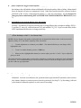
d.
EEG: Seven Grass gold cup electrodes ( C3, C4, O1, O2, M1, M2, Ground) will be
placed on the scalp (Figure 3) and held in place with electrode cream (such as
Elefix or Ten-20) covered with gauze squares or cotton balls. Using the
International 10-20 system, measure the head to locate the site and mark each site
with a water soluble, non-toxic soft marker. Directions for measuring the head are
outlined below.
1.
Refer to Figure 3 for the location of the sites. Even numbers refer to the right
side of the head; odd numbers to the left and Z to midline.
2.
Use a flexible, disposable/washable centimeter tape and,
3.
Place the 0 cm end of the tape on the nasion (depression between the nose
and forehead) and direct the tape to the back of the head. Read off the cm
at the inion (the protuberance at the back of the head.)
4.
With the tape still held in place, locate the halfway point of your nasion-inion
distance. For example: if the nasion-inion distance is 25cm, 12.5 is the
midpoint. Mark this point (CZ.)
5.
Leaving the tape in place, measure up 10% from the nasion (2.5cm in our
example.) This is the FPZ site on the forehead. (Locate the ground
electrode about 30% of the distance from the nasion to the hair line.)
ςΙΙ−17
10/02/95
6.
Repeat this process from the inion: 10% up on the midline is OZ.
7.
Remove the tape and place one end on the preauricular point (the
depression in front of the ear) and direct the tape across the head through
the CZ mark to the other preauricular point. Note the distance in cm.
8.
With the tape in place find the point that is half the "ear to ear" distance and
mark the intersection with your nasion-inion CZ mark.
9.
With the tape still in place, measure up 10% from the preauricular point on
each side of the head (T3 and T4 in Figure 3) then measure 20% up from T3
and mark C3; measure 20% up from T4 to mark C4.
10.
Measure the circumference of the head by placing the tape along the 10%
markings all the way around. Note half the distance and then calculate 10%
of this distance.
11.
Mark 10% to the left and right of FPZ; these points are FP1 and FP2. Direct
the tape through FP1 back to the 10% marks on the left side of the inion at
the circumference line. Mark the intersection. This intersection is 01.
Repeat this process on right side from FP2 to locate 02.
12.
M1 and M2 are the left and right mastoid, respectively. Palpate the bone
behind the ear and avoid any blood vessels to reduce ECG artifact.
Abrade sites with Omniprep or similar substance on cotton tip applicator. Fill the gold cup
with paste and press firmly to prepared site. Hold in place 10-20 seconds; cover with
gauze or cotton ball. Be sure cable-lead wire is directed away from face toward back.
Repeat for each site. When all are placed, check impedances on ALICE 3 impedance
screen. All values should be less than 10K ohms (green or yellow lines). Lead wires
should be secured in a "pony tail" with all the other face and head wires.
ςΙΙ−18
10/02/95
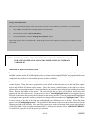
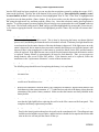
Standard International 10-20 placement sites for scalp electrodes. CHIME
designations are shown as solid circles. Due to the way ALICE3 references
are hardwired, the ipsilateral scheme must be overridden by manually
reversing the lead pins placed into M1 and M2. That is, plug the scalp M1
lead into the ALICE3 input for A2 and lead for M2 into input for A1. The EEG
ground will be centered on the forehead midline approximately 20-30% up
from the nasion.
FIGURE 3
ςΙΙ−19
10/02/95
e.
Submental EMG:
1.
2.
Preparing the skin site.
a.
Clean (3) skin sites on the chin where the electrodes will be applied: See
Figure 4.
1.
Tip of the chin.
2.
Right digastric muscle (as far back on lower jaw).
3.
Left digastric muscle (as far back on lower jaw).
b.
The priority in selecting the combination of sites to measure chin EMGs are:
1.
The tip of the chin and the right digastric muscle.
2.
The tip of the chin and the left digastric muscle.
3.
The left and right digastric muscle.
Preparing the electrodes.
a.
b.
c.
d.
e.
3.
The surface and cavity of the electrode should be clean and dry to attach the
adhesive washer (double-sided adhesive discs) and to fill the cavity with
electrode gel.
Remove the adhesive washer from its backing strip using the blue tab, and
apply the adhesive washer to center the hole over the electrode cavity.
Press adhesive washer down to seal the surface of electrode.
Squeeze Signa Gel electrode gel to just fill the cavity. Check that NO
BUBBLES are introduced in to the cavity.
Remove the round backing paper for the adhesive washer and place the
electrode on the prepared skin surface.
Press the electrode down firmly to attach and seal the electrode to the skin.
Cleaning the electrodes after each use.
a.
b.
c.
d.
Remove the main bulk of the gel with a cotton swab.
Use distilled or deionized water to wash out remaining gel inside the cavity.
NEVER USE TAP WATER.
Soak electrode in a container with mild saline solution until the next
application.
Do not allow the “old” gel to dry or harden in the cavity.
Please annotate on Alice (you may type in “G-electrodes”) when you use the GEREONICS
EMG electrodes. Doing so will allow the PSG reviewer to know when these electrodes are
being used.
After application of EEG and EMG electrodes, check impedances with the ALICE3 and, if
available, the Cleveland impedance meter, and note them down on Form F1. Be prepared
to enter these values later onto the ALICE3 screen at study initiation.
To check impedance and get a better idea of how good your connections are, press
<F10>. The screen will provide a color-coded, graphic representation of the top of the
patient's head with the selected montage indicated:
ςΙΙ−20
10/02/95
COLOR
COMMENT
green good signal
yellow warning (watch the electrode, there may be a problem)
red
bad signal (poor connection, recheck the electrode)
IMPEDANCE
<5K ohms
5-10K ohms
>10K ohms
If impedances on EEG and EMG are less than 10K ohms, the head can be wrapped with
Kerlix to secure chin and head electrodes. See Figure 5 for head wrap pictures.
Filter settings must be adjusted at the time you check impedances. The following settings
must be adopted by each site:
EEG:
Low Pass
40 Hz
High Pass
1.0 Hz
EMG:
45 Hz(default)
5.0 Hz
Notch Filter:
ON
Filter
settings are toggles
and directions appear on the bottom of the ALICE 3 monitor. A checklist of tasks that
need to be carefully performed is provided in The CHIME POLYSOMNOGRAPHY
CHECKLIST (Form F1, Appendix B).
ςΙΙ−21
10/02/95
EOG AND EMG ELECTRODE PLACEMENT
FIGURE 4
ςΙΙ−22
10/02/95
H
E
A
D
W
R
P
IL
U
S
T
O
N
FIGURE 5
ςΙΙ−23
10/02/95
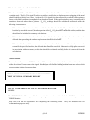
f.
Pulse Oximeter (SaO2): Place the probe light source on the top of the baby's left foot.
Wrap the stretch tape around the foot so that the detector is on bottom of the foot
opposite the light source, Figure 6. Direct the lead wire up the body or out the bottom of
the sleeper. A Posey may be used to further secure the probe on the foot.
g.
Position Sensor: Tape to the back of the baby's diaper with the blue DOT away from the
body.
h.
PETCo2: A nasal cannula to sample air for continuous PCO2 determination is secured in
front of the nares. (Refer to capnograph directions at each site.)
i.
Thermistor: Prior to placement on infant check operation by blowing on sensors and
observing waveforms on ALICE3. If no waveforms replace! Clean sensor. Affix the
double-sided tape on the back of the Healthdyne nasal/oral thermistor. Press the sticky
side under the nose so that the tips are in front of but not touching the nares and mouth. It
may be necessary to carefully bend the tips slightly away from the brown strip. See Figure
7.
j.
Actimeter: With actimeter connected to CALVIN shake it gently to establish that it is
operational. Black boxes/rectangles should appear on the ALICE3 screen during
acquisition mode if it is working. If not, use alternate. Repeat process. Place the
Healthdyne actimeter on the bottom of the right foot and secure with tape.
k.
LEOG/REOG: Prepare the sites with alcohol or Omniprep. Use Contour IB snap or gold
cup electrodes and place LEOG 0.5 cm above and 0.5 cm away from the outer canthus of
the left eye; REOG is placed 0.5 cm down and 0.5 cm away from the outer canthus of the
right eye. Direct lead wires away from the face and into the "pony tail." See Figure 4.
ςΙΙ−24
10/02/95
Probe is placed on left foot with red light source on top of foot. Tape to foot so that the detector is on the
bottom of the foot opposite the light source.
PULSE OXIMETER PLACEMENT
FIGURE 6
ςΙΙ−25
10/02/95
Understanding CALVIN
The illustration below shows a top view of the cover plate.
The red LED light provides various indications:
- a continuous, steady light indicates that
the unit is powered on and is ready for
signal acquisition;
- a slow, flashing light indicates data is
being transferred; and
- a fast, flashing light indicates an error
condition
The cable from the patient box plugs
directly into the 50-pin INPUT DEVICE
connector.
Figure 8
WARNINGS AND CAUTIONS
These Warnings and Cautions apply specifically to the CALVIN amplifier unit.
)
Never pick up the unit by the cover plate. Always use two hands to handle the unit by its
base.
)
Always place the unit on a sturdy, level surface.
)
Do not set the unit on a polygraph or on top of a computer monitor.
)
Do not expose the unit to heat or direct sunlight.
)
Do not attempt to autoclave, EtO, gas or pressure sterilize the unit.
)
Do not place the unit within three feet of oxygen tanks or oxygen tents.
)
Do not drape the cable to the computer over a polygraph, light fixtures, or medical devices.
)
Do not use the cable if it appears to be damaged, broken, or frayed.
)
Do not attempt to service the unit if it does not appear to be working properly.
ςΙΙ−26
10/02/95
H
E
A
L
T
D
Y
N
R
M
IS
O
P
L
A
C
E
N
T
F
IG
U
R
E
7
ςΙΙ−27
10/02/95
8.
CHIME Monitor Signal Evaluation
Each infant enrolled in the CHIME protocol will bring her (his) CHIME Monitor to the sleep
laboratory. If the parents do not bring their monitor, use the backup monitor assigned to the
Sleep Lab. Plug in the monitor. The cartridge from the CHIME Monitor should be replaced
with a newly initialized cartridge for use during the overnight polysomnogram. Consult PSG
cartridge parameters in Appendix B. When the baby is quiet, the CHIME monitor, positioned in
the sleep room, can be started. This event recording system will be used at its preset record
settings for the duration of the polysomnographic recording.
ςΙΙ−28
10/02/95
9.
Connecting the Infant to Infant Patient Box/Calvin
(From: Healthdyne ALICE 3, User Manual 1994).
Understanding the Patient Connector Box
The illustration and call-outs below describe the appropriate CHIME inputs for the Infant Patient Box.
Figure 9
WARNINGS AND CAUTIONS
These Warnings and Cautions apply specifically to the Patient Box.
) Never place the unit on top of a polygraph or other medical devices.
) Use only the connectors that have been supplied with the Alice 3 System.
) Use only the accessories that have been recommended by HealthDyne.
ςΙΙ−29
10/02/95
Connecting the EEG Electrodes
1. Plug the right mastoid electrode into the left reference inputs of the Patient Box, and the left
mastoid electrode into the right reference input.
2. Insert all of the leads that you have attached on the patient into the appropriate connectors on the
Patient Box.
3. Insert the lead pin from the Ground EEG electrode into the ISOGROUND receptacle on the
Patient Box.
Completing the Connection
Insert the connector end of the Patient Box into the 50 pin cable connector on the top side of Calvin,
Figure 8.
Connect CHIME Monitor to CALVIN with Computer Interface Cable
The CHIME Monitor leads are already connected to the CHIME monitor. Check all connections and
make sure the PSG cartridge is in the CHIME Monitor. Turn the CHIME Monitor on to check the
quality of the CHIME monitor cardiorespiratory signals and pulse oximetry. REMEMBER the ECG
you see on the screen is from ALICE 3 not CHIME Monitor.
Never plug in or unplug PC Calvin phone jack if ALICE is on.
ςΙΙ−30
10/02/95
10.
Positioning Infant
The electrode array does not permit monitoring in the prone position. Babies should be laid
supine, or their backs may be propped slightly with a clean, rolled up blanket or towel. Infants
under one month of age should be swaddled, while mittens or arm restraints may be used in
older infants. You are now ready to begin the acquisition. Never plug in or unplug PC Calvin
phone jack if ALICE is on.
11.
Environmental Conditions
Covering of the infant depends on room temperatures. Efforts should be made to maintain
room temperatures between 22 and 24 degrees centigrade; when a thermostat is available,
choose the 23 degree setting. Ambient light should be comparable among centers but control
of ambient noise can probably not be assured. Unexpected noises such as sirens must be
annotated on the chart. A nightlight not exceeding 40 watts should remain on in the infant
room. Infants will be dressed in a dry disposable diaper (2 tog units), one piece sleeper (2 tog
units), and covered with 2 flannel blankets (3-4 tog units).
12.
Assessing Signal Quality
The signals should be stored on ALICE while you are performing these tasks. The light should
be dimmed and, when personnel and parents/caregivers have left the infant room, the
recording can begin. Allow a half hour to an hour for channel and baby adjustments. If the
quality of one of the signals is poor, limited re-application can be contemplated at this time.
The art and skill of overnight polysomnography in infants pivots on the adequacy of the initial
application. This should be done thoroughly, quietly and without unduly upsetting the baby.
Rushing through it is not advisable even with a late start because a shortened recording of high
quality is more valuable than a long one with deteriorating signals.
Although the infant cannot be asked to perform the maneuvers requested of older children and
adults, the signal quality can be assessed by observing spontaneously occurring behaviors.
When the child is awake, there should be a good quality EOG signal with the left and right EOG
of opposite polarity. If the eye movements are recorded but are of the same polarity, check the
position of the electrodes.
Be sure there is a good quality chin EMG signal that increases during crying or sucking. Adjust
the gain, check electrode position and/or plug in a different pair of EMG electrode leads until a
good quality signal is reached. If ECG artifact is present in the EMG channel, choose a
different pair of electrodes to select the signal. If active REM's observed prior to the begin
calibration, that is during AS, adjust the gain on the chin EMG so minimal tonic muscle activity
is recorded (the signal should not be totally removed since some muscle activity will then be
lost). The near isoelectric EMG tracing can then be used to make amplitude comparisons
between states. During the recording, periodic checks should be made to ensure that no
change to artifact amplitude has occurred.
Observe the baby's breathing and be sure that synchronous breathing is reflected in
synchronous chest wall and abdominal signals. If the chest wall and abdomen appear to be
out of phase on ALICE 3, be sure that the child's breathing is out of phase on inspection.
Move the baby's foot that is connected to the actimeter to be sure that motion can be detected.
Since there is no gain adjustment on this channel, if the signal is unsatisfactory, the actimeter
must be reapplied.
13.
Test Signal Transfer to DAS. See Appendix A.
ςΙΙ−31
10/02/95
14.
Synchronization of time clocks between ALICE 3 computer and CHIME monitor.
By synchronizing the ALICE 3 computer, and the CHIME monitor, events recognized by one
system can be compared with events recognized by the other system.
Both systems record events based on the time of day they occur. This time is derived from each
of the computer system's clock. However, the CHIME monitor clock may not be set at the TRUE
time of day. This is mainly due to the fact that all CHIME monitor clocks are set to local standard
time and are not updated when Daylight Savings goes into effect. ALICE 3 computer clocks
should always by checked prior to the PSG to insure that they reflect the TRUE time of day.
For technical reasons, no attempt will be made to synchronize the two computer system clocks.
Instead, a calibration signal common to both systems will be simulated at the beginning of the
PSG and at the conclusion of the PSG. This simulated signal will then be used to calculate the
offset in time between the two systems so that events can be compared.
The simulated calibration signal will be created on the ALICE 3 Oximeter PULSE channel by
disconnecting the Oximeter Cable from the CHIME monitor in the following manner (Note: the
oximeter sensor should already be attached to the infant's foot):
*
Just prior to the one minute of calibration markers, with CHIME monitor on for at least 5 minutes.
1.
Disconnect the Oximeter cable from the CHIME monitor by depressing the spring lock on the
connector and removing the cable from the monitor.
2.
Count to 10 (one-one thousand, two-one thousand, etc.).
3.
Reconnect to Oximeter cable to the CHIME monitor.
4.
Count to 10 (one-one thousand, two-one thousand, etc.).
5.
Disconnect to Oximeter cable from the CHIME monitor.
6.
Count to 10 (one-one thousand, two-one thousand, etc.).
7.
Reconnect to Oximeter cable to the CHIME monitor.
*
After END study calibration markers and before the cry recording (while data is still being saved to the
optical disk):
1.
2.
3.
4.
5.
6.
7.
Disconnect the Oximeter cable from the CHIME monitor.
Count to 10 (one-one thousand, two-one thousand, etc.).
Reconnect to Oximeter cable to the CHIME monitor.
Count to 10 (one-one thousand, two-one thousand, etc.).
Disconnect to Oximeter cable from the CHIME monitor.
Count to 10 (one-one thousand, two-one thousand, etc.).
Reconnect to Oximeter cable to the CHIME monitor.
ςΙΙ−32
10/02/95
The technician will verify that each step of the synchronization procedure is completed on the CHIME
POLYSOMNOGRAPHY CHECKLIST (F1).
ςΙΙ−33
10/02/95
15.
Calibration
When you are satisfied with the quality of the signals, calibrate for 1 full minute, beginning on
the minute. The onset of calibration marks the onset of computer analysis for the CHIME
protocol. From this time onward, the computer can not be turned off until the completion
of the end calibration. Please note the warning above. EEG and EMG signals should not be
reapplied and calibration should not be undertaken in the middle of recording.
A calibration signal of 100 microvolts can be displayed for the EOG, EEG, EMG, and ECG
channels. Press <F9> at the Raw Data screen and you will be transferred to the Calibration
Signals screen to see this signal. Since you must know the amplitude of the EEG signals, this
screen will indicate whether the internal amplifiers are working correctly and responding equally
to the 100 microvolt signal. Check all EEG channels to make sure they are identical in
appearance. You should access the Calibration Signals screen at the beginning and at the end
of the study to visually check that the amplifiers have worked correctly during the study. If after
looking at the Calibration Signals screen the EEG signals look differently or are not responding
correctly, contact Healthdyne.
The official start time when the rules of intervention become active is after the calibration
period. Some laboratories call this "lights out", although the lights may have been out for a
long time already. For this protocol, designate this as "begin study".
16.
Chart Annotation
During the PSG recording, complete annotation is important for interpretation of physiological
data, identification of artifact and sleep state coding. The behaviors and activities to be charted
are outlined in Table 5A, ITEMS TO BE ENTERED INTO ALICE 3 AND ON THE PSG
CHECKLIST (F1 FORM).
The CHIME STUDY: PSG ANNOTATION CODING SHEET (Table 5B) minimizes the number
of codes that are used during annotation of the PSG. This CODING SHEET should be posted
next to ALICE so that it can be used during the PSG.
a.
Technicians should code all infant movements and behaviors using the codes defined on
the CHIME STUDY: PSG ANNOTATION CODING SHEET.
1.
Caregiving: Feedings, diaper changes, comforting of the infant are examples of
caregiving. These periods will be designated as Awake. Annotate the beginning of
caregiving period by typing BEGIN. Use TABLE 5A: ITEMS TO BE ENTERED ON
ALICE to assist with the type of information that should be recorded during
caregiving periods. Annotate the end of the caregiving by typing END.
2.
Interventions: Technical adjustments to sensors or interventions other than for
caregiving. These periods may still be designated to an infant sleep state. It is
essential that these periods be clearly and accurately described. Annotate the
beginning of the intervention by typing IN. Describe the intervention. Use
TABLE 5A: ITEMS TO BE ENTERED ON ALICE to assist with the type of
information that should be recorded
ςΙΙ−34
10/02/95
during an intervention. Annotate the end
of the intervention by typing OUT.
b.
c.
Especially note that when feeding, the baby may drop off to sleep. The person with the
baby must notify the annotator. If the mother is present, she needs to be instructed not to
intervene unless, e.g., for feeding. Note: a pacifier is allowed during monitoring, but the
room should not be constantly entered to insert a pacifier which has fallen out.
1.
Technicians must clearly annotate Awake and Asleep periods. Use the EC and EO
comments to denote these periods.
2.
If during quiet sleep no special events happen, make a notation anyway every 5
minutes. Consider putting the annotation chart in plastic and keep it handy. It is
very important to comment EC or EO.
Infant movements or behaviors that cannot be placed in one of the listed categories on the
CODING SHEET should be annotated by typing in a description of the movement or
behavior.
In summary:
17.
1.
Annotate caregiving periods by typing BEGIN, followed by a description of the
caregiving activity, and when the caregiving is completed, type END. These periods
will be designated as Awake.
2.
Annotate Interventions by typing IN, followed by a description of the intervention,
and when the intervention is completed, type OUT. These periods may still be
assigned an infant sleep state.
3.
If you are unsure whether an activity is an Intervention or a Caregiving period, use
the codes for Interventions and then describe the intervention.
Guidelines for Re-application of Electrodes During PSG Recording
Electrodes may get dislodged. Since sleep and wakefulness are target variables, awakenings
for electrode re-application should be the exception. For the purpose of this study, an infant
should only be awakened if the EtCO2, the ECG or SaO2 tracings have been lost. No effort
should be made to re-apply the EEG and EMG electrodes since such re-application will almost
certainly arouse the infant and preclude undisturbed sleep. During spontaneous awakenings
for feeding, the eye movement sensor, the nasal/oral thermistor, or other sensors can be
readjusted, if necessary. After diaper changes, remember to retape the position sensor to the
back of the diaper.
ςΙΙ−35
10/02/95
TABLE 5A
ITEMS TO BE ENTERED ON ALICE3 AND ON THE PSG CHECKLIST (F1 FORM)
PLEASE ENTER INFORMATION ASSOCIATED WITH THE TOPICS LISTED BELOW INTO ALICE
AND ON THE PSG CHECKLIST (F1 FORM).
TECHNICAL DATA: Enter BEGIN when the caregiving starts, describe the caregiving, then enter END
when it is completed. Caregiving procedures are those that generally involve the infant being in an
awake state. Examples include:
•
•
•
EEG and EMG impedances values.
Changes in gain to any of the channels.
Any problems associated with the operation of ALICE.
Caregiving: Enter BEGIN when the caregiving starts, describe the caregiving, then enter END when it is
completed. Caregiving procedures are those that generally involve the infant being in an awake state.
Examples include:
•
•
•
Infant feedings: what, how long, amount, burping periods, etc.
Diaper changes.
Comforting, patting rocking.
INTERVENTIONS: Enter IN when the person enters the infant’s room, describe the caregiving, then
enter OUT. These are interventions that do not necessarily awaken the infant. Examples include:
•
•
•
•
•
•
Nurse/Parent/Technician entering the infant’s room.
Nurse/Parent/Technician touching the infant.
Removal or addition of blankets.
Re-application of sensors, i.e. EtCO2, ECG, SaO2.
Responses to alarms.
Emergency procedures.
ENVIRONMENTAL CONDITIONS; Enter this information directly into ALICE at the time it is obtained.
These are changes in the environment that could affect the infant’s sleeping. Examples include:
•
•
•
•
Bi-hourly temperature and humidity.
Sirens or exceptional noises.
Lights out and lights on period (dimlight should remain on).
Conditions such as lightning and searchlights that affect sleep.
ςΙΙ−36
10/02/95
TABLE 5B
CHIME STUDY: PSG ANNOTATION CODING SHEET
BEHAVIOR CODING: PLEASE USE THE CODES LISTED BELOW AND ENTER THE CODES AS SOON AS
POSSIBLE AFTER THE BEHAVIORS ARE OBSERVED.
Codes
EO
EC
Definition and Description of Coding Item
AWAKE vs. ASLEEP Periods:
Eyes Open
Indicates that the infant is awake.
Eyes Closed
Indicate that the infant is asleep.
* If infant is asleep and no behaviors are noted for 5 minutes, enter EC.
IN
OUT
INTERVENTIONS; Enter IN, then describe the intervention, then enter OUT.
Person IN infant’s room.
Person OUT of infant’s room
BEGIN
END
Caregiving;
Enter BEGIN, describe the caregiving, then enter END.
Beginning of caregiving period
End of caregiving period.
BM
Body Movements:
Stretching
Rolling over
Jerky movement
Twitching
Writhing
Limb movements
STR Startle:
Use BM to describe any of the body movements listed below.
Slow, extending movement of trunk or hand or extremities.
Change in position between lateral, supine, or prone.
Accelerated, quick movement involving one or more extremities.
repetitive, sudden, quick jerky motion.
Twisting or turning movements, squirming, contorting.
Movement of one or more extremities.
Sudden unexpected movement, usually involving all extremities.
FM
Facial Movements:
Smiling
Grimacing
Yawning
Use FM to describe movements involving the face and mouth
Joyful facial expression.
Discontented facial expression.
Wide, open mouth, with prolonged inhalation.
MO
Mouthing:
Repetitive, open and closing of the mouth.
SUCK
Sucking:
Periodic sucking movement of mouth and lips.
SIGH
Sigh:
BPAC
EPAC
BCRY
ECRY
VOC
Long, deep, audible exhalation.
PACIFIER USE
Begin Pacifier
The infant has begun using a pacifier.
End Pacifier
The infant has ended the use of a pacifier.
VOCALIZATIONS
Begin Cry
Beginning of a crying period.
End Cry
End of a crying period.
Other vocalizations
Sounds produced by the infant, including those listed below:
Whimpers
Low, whining, broken cry sounds.
Babbling
Incoherent vocal sounds.
Grunting
Short, deep, hoarse sounds.
ςΙΙ−37
10/02/95
Hiccough
Sharp quick sound caused in involuntary contraction of diaphragm.
ANNOTATE ALL OTHER BEHAVIORS BY TYPING IN A DESCRIPTION OF THE BEHAVIOR.
REFER TO TABLE 5A FOR ADDITIONAL INFORMATION CONCERNING TECHNICAL DATA AND
ENVIRONMENTAL CONDITIONS THAT SHOULD ALSO BE ANNOTATED.
ςΙΙ−38
10/02/95
18.
Nurse/Technical/Caregiver Interventions
Routine infant care will be continued during the PSG. Nurses/technicians can help mothers breast feed
their infants at the crib/bedside without substantially affecting the quality of the recording. Infants should
always be burped well prior to resumption of sleep. Other interventions should be restricted to those
predicated on the severity of physiological patterns, i.e. only for resuscitation. See E. Protocol for
Emergency Intervention during PSG and CHIME POLYSOMNOGRAPHY CHECKLIST (Form
F1).
19.
Adjustment of Waveforms During PSG Recordings
During the PSG recordings waveforms should be continuously scanned to see whether adjustments are
necessary. All channels except the following may be changed during the overnight recordings: EEG (14), position (7), temp (8), cardiotachometer (10), and endtidal CO2 (15). Expect seconds delay before
ALICE implements the direction to change sensitivity.
Adjusting the Gain
(From: Healthdyne ALICE 3, User Manual 1994).
NOTE: Only the channels with numbers displayed below the channel label abbreviation on the screen can be
adjusted, namely, ECG, chin EMG, respiratory effort, and airflow.
1. To make adjustments to a channel, press <ESC>. The channel label that you can change will be
highlighted in red.
2.
To move to another channel, press the <TAB> key.
3. When you have highlighted the channel you want to adjust, press the "+" and "-" keys to adjust the
gain up or down.
The signals and activity shown on the screen must be checked on a regular basis to determine if gain adjustments
are necessary. It is recommended that you wait for more than a minute to check the change on the screen after
you have made any type adjustment.
20.
Termination of Monitoring
Monitoring should be terminated after no less than 8 hours of recording, that is, 8 hours between
calibrations. After the end calibration, the synchronization signal should be simulated on the oximeter
pulse channel, then the cry analysis protocol must be performed, (See Step 23, Cry Recording), followed
by the identical calibration sequence as at the onset of recording.
ςΙΙ−39
10/02/95
To stop data acquisition, follow these steps.
How to exit the system
(From: Healthdyne ALICE 3, User Manual 1994).
In a normal acquisition, the recording of information will stop at the time you selected on the Patient
Information screen. However, if you want to stop the study before this time, you have two options:
•
Press <ALT> + S to stop the study and abort the program immediately.
•
Press <CTRL> + <END> to discontinue the study within a three-minute window. When
you initiate this command, the system will continue to record (from 0 - 3 minutes) until it reaches the
end of the current three-minute time frame. You will receive the message, "Scanning, please wait."
At this time, the software will close all of the collected files, the recording will then stop, and you
will be returned to the Main Menu. All information recorded up to this point will be saved as if the
system recorded until the original study end time.
After completion of this sequence ALICE 3 can be turned off and the infant room can be entered. Prior to
removal of any electrodes, check and note the end impedances of the EEG and EMG electrodes. Upon
removal of electrodes check their condition carefully. Remove the paste remnants with some lukewarm
water and prepare the infant for return to the nursery or departure with the parents. Apprise parents of
any redness or rashes that have been observed and how to take care of these. On the Form F1 note any
special circumstances, especially adverse reactions to paste, tape or heat on the infant's skin. Study
personnel should also complete an H2-Visit form to document how the CHIME monitor functioned
throughout the PSG. On Form H2-Visit, under "Type of Contact", check PSG Comparison.
Before the CHIME monitor is returned to the caregivers for home use, replace the PSG cartridge with a
newly initialized cartridge in the event mode and give caregivers a new Alarm Log (Form H5) to take
home. Enter both cartridge serial numbers on the H2-Visit form. If the monitor was found to
malfunction during the PSG, a replacement should go home with caregivers.
21.
Site Assessment of PSG Quality
The designated CHIME Study PSG Reviewer is responsible for maintaining the quality of the PSGs from
that site. As soon as possible this person should review each PSG recording and should complete page 5
of the CHIME POLYSOMNOGRAPHY CHECKLIST (Form F1). The primary aim is to identify and
immediately resolve problems to insure improved subsequent recordings. Any information should be
reviewed with the PSG technicians who performed the recording so that appropriate changes and
modifications will be made.
The completed page 5 should be forwarded to DCAC for inclusion with the rest of the PSG
documentation.
ςΙΙ−40
10/02/95
22.
DCAC Assessment of PSG Quality
The DCAC has implemented a standard review process for all PSGs. The results of the review are
summarized on DCAC: PSG QUALITY REVIEW FORM. See Appendix B. A copy of this review is
included with each disk that is returned from the DCAC to the CHIME site. The purpose of this form is
to document the PSG quality and to provide feedback to each site concerning the quality of the PSG as
compared to PSGs collected from all other sites. PSG personnel at the site should review this form If
there are any questions or comments concerning the results of this review, these should be discussed first
with the local CHIME PSG REVIEWER and, if necessary then contact the DCAC for further clarification
DCAC PSG QUALITY REVIEW FORM: A summary of the qualities of the PSG signals, in respect to
any problems that may have occurred during the PSG recording session will be documented on the
DCAC PSG QUALITY REVIEW FORM.
The header region of the form summarizes information relating to the site, Study ID, PSG date, optical
transmittal disk, and who completed the PSG review.
Subsequent sections:
1-22. Signal quality: summarized each channel of data. A subjective determination is made as to whether
the signals are of sufficient quality to be used for scoring purposes. In general, the quality of the signal
must be adequate for at least 2/3 (66%) of the night. Channels that are highlighted are those that are most
important to sleep state and respiratory scoring. If a signal is deemed unscorable for the majority of the
night, a comment is made as to the reason for the signal being unscorable.
23-24. Annotations: Awake periods must be clearly marked. Likewise, movements should also be
clearly annotated.
25. Filter Settings: These are determined from the data in the user event table and should be the same as
those already listed.
26. Calibrations: EEG and EMG calibrations are the ALICE calibrations that designate the beginning and
end calibration times for the PSG. The NIMS calibration are the times that the CHIME monitor was
synchronized with ALICE.
27-20. Indicate whether PSG documentation material was received at the time the PSG was reviewed.
30-31. Indicate whether all the data from the PSG was retrievable from the optical disk. If a problem
with restoring the data occurs, a description of the problem and a request for additional information or for
the site to resubmit the data may be made.
32. Overall comments: These are general comments concerning the DCAC review of the PSG.
ςΙΙ−41
10/02/95
23.
Cry Recording
All study infants will have a cry session at the conclusion of the PSG with the sensors still on the infant
and the ALICE 3 still "on". Refer to Manual of Operations, section VIII, Cry Protocol.
ςΙΙ−42
10/02/95
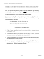
E. Protocol for Emergency Intervention during PSG
EMERGENCY PROCEDURE DURING POLYSOMNOGRAPHY
There will be very few instances during the carefully monitored and supervised
overnight polysomnographic recordings when clinical interventions will be indicated.
The baby will be on the CHIME Monitor in the continuous mode.
If an apnea greater than 20 seconds in duration occurs, it is advisable to look at the
SaO2 and heart rate. If a downward trend is evident, go look at the baby, refraining
from stimulating her (him) until:
a. SaO2 desaturation <85% for >30 seconds, or
b. Heart rate <60 bpm for at least 10 seconds.
EMERGENCY INTERVENTION
1. If baby is having a significant clinical event as described above, stimulate the baby
by flicking the heels.
2. If the significant clinical event continues, make sure airway is patent, reposition
and suction if needed, and bag baby with a few puffs of O2.
3. If the perfusion and SaO2 do not return to previous levels, continue to bag baby
and call appropriate code for physician.
4. If seizure activity is noted (rather than tremors), verify the EEG. Check for
cyanosis and airway patency. Provide supplemental O2 to maintain saturation at
pre-seizure level. Page the appropriate physician.
ςΙΙ−43
10/02/95
F. PSG SCORING
1.
Introduction to Scoring
Scoring protocols are designed to describe:
1. Sleep and waking states
2. Several aspects related to event occurrences, including:
a. characteristics of events that occurred during the overnight PSG study
b. ALICE PSG event scoring as compared to CHIME Monitor scoring
• the accuracy of event detection
• the significance of small chest or abdominal deflections
3. EEG, respiratory and cardiac summary variables for the entire study
To achieve these goals the protocols described below are to be followed. Except for Step 2, scoring will be the
responsibility of DCAC.
2.
Procedures for Scoring
AT ALICE
STEP 1: QUALITY
CONTROL
Load the appropriate optical disk and check whether the Infant ID # is correct and identifying
information complete. If not, remedy.
•
To begin scoring, turn ALICE system on. When menu appears, select ALICE 3 option.
(Please refer to Healthdyne ALICE 3 Manual as needed.)
•
On Main Menu, select View Patient by pressing <ENTER> or CLICK on L mouse button
when arrow is on View Patient (or press "V" on keyboard).
•
From list of saved acquisitions, select study to be scored, press <ENTER> or click L mouse
as usual.
•
Check box at upper right of screen to be sure you have the study you want. If not, click R
mouse and return to Main Menu and try again.
ςΙΙ−44
10/02/95
STEP 2: INITIAL SURVEY AND DCAC
COMMUNICATION
Step 2 should be performed within three working days of the recording so that subject and personnel can
benefit.
1.
Review the data for clinical events that require immediate attention and/or notification of a physician.
During the night the technician will have flagged these on the comment sheet. Each laboratory has its
own directives for this category.
2.
Principal Investigator or designated individual scans the ALICE tracings and comments in order to
provide feedback to PSG personnel and CHIME. Fill out the Feedback to PSG Personnel on Page 5 of
Form F1 and post a copy in the laboratory if you wish.
3.
Consult CHIME PSG Form F1 and mail to DCAC in the weekly Transmittal Log.
4.
Consult CHIME Communication Log for inquiries from PSG personnel.
Material to be sent to DCAC:
1.
DCAC Transmittal and Disk Log sheet, Optical disk with ALICE 3 patient
data (disk will be returned promptly)
2.
Patient identification sheet
3.
CHIME PSG Checklist (Form F1, pages 1-5)
ςΙΙ−45
10/02/95
ςΙΙ−46
10/02/95
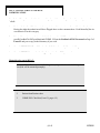
STEP 3: INITIAL ALICE
REPORT
Obtain a printout of ALICE 3 automatic output and file away for future reference.
From Healthdyne ALICE 3, User Manual 1994 Chapter VI: Reports
NOTE:
The "Print Analysis Report" allows you to generate reports summarizing the acquisition. After
selecting this option, a list of all saved acquisitions will be shown. Studies highlighted in green have not been
saved to the optical drive and are still in the work directory. The study number, acquisition date, patient's name,
and montage name is shown for each study. After selecting a study, the reports selected under the "Printer
settings" option on the Configuration Modification menu will be printed. Although you may not choose to
print them all, there are 11 available reports for adults and 10 available reports for infants (some reports have
multiple pages). Each report type is listed below. Select the starred reports and file.
* Recording Identification/Information
* Technical settings
* Signal Quality Analysis
* Sleep Data (adult studies - 3 pages/infant studies - 1 page)
* Respiratory Events (adult and infant studies - 3 pages)
* Heart Rate Summary
pH Summary (infant studies only)
* Oxymetry Summary (adults and infant studies - 2 pages)
CPAP Report (adult studies only)
Miscellaneous results - Snoring and Myoclonus Summaries (adult studies only)
* Allnight Screen
* Event List
STEP 4. SLEEP/WAKE STATE (STAGE)
SCORING
Note: Study sites will not be responsible for completing Steps 5-9. They are included for documentation
purposes only.
DEFINITIONS:
Sleep state/wake coding will follow the guidelines of Anders, Emde, Parmelee (1971). This method will be
applied to infants through one month of age as well as older infants. Some centers will also follow the sleep
stage scoring guidelines of Rechtschaffen and Kales (1968) in infants ≥ 3 months of age (PCA).
ςΙΙ−47
10/02/95
PROCEDURES:
1.
Select scoring Alternate Montage 1 (must include EEG (C3-M2; C4-M1; O1-M2; O2-M1; LEOG/REOG
and/or EM; EMG; ECG; abdominal respiration; airflow; CO2 waveform; SaO2 waveform and actimeter).
NOTE:
Look at ECG to screen for arrhythmias and to be able to correlate the R waves with artifacts
in other channels.
Comments will automatically be reprinted on the raw data screen. Refer to data acquisition section for
abbreviations, Table 5B.
2.
Retrieve the event log (from Step 1) for this infant. To get a general impression of the recording and to
identify periods of wakefulness/feeding, scan this log. When you get to these epochs, determine whether
you agree with ALICE 3 decisions. If baby is awake you can assign a "W".
Also on the report print out, note the gestational and post-conceptional age, so that you know whether to
expect certain patterns such as trace-alterant or sleep spindles.
3.
Go to the All Night Screen (F3) and select samples of AS, QS, and Awake (that is A, Q, W per ALICE
scoring). Determine whether the EMG varies in level according to sleep states. If it does not, look
further into the record to see if tonic variations are present. If there is no variability, eliminate this
channel from scoring.
4.
Go to the raw data screen (F4) and verify that you are at the first full epoch after the onset calibration.
Start scoring at the first full minute epoch after calibration. 17:00 not 16:59:30.
5.
Individual parameter codes will be assigned to each epoch between onset and offset calibrations. See
Appendix B.
When is a signal good enough to serve as one of the five parameters? This must be established by
gaining an overview of the recording during the night, in particular during A, Q and W. Fill in "X", if
data is unavailable. Irregular respiration in preterms will make many epochs "I" for irregular and hence
Indeterminate Sleep (IS). Keep that information rather than force the epoch into quiet sleep. Parameter
codes are in Table 6 and in parameter scoring section that follows.
Parameter scoring
a.
EM: Determine if one or more REMs occur in the epoch. If a REM is present, code as +; otherwise.
b.
EEG: Check the frequency of the EEG by clicking mouse and manually counting the number of
cycles and reading the Hz/cycles per second. Always look at C4/A1 unless it is obscured or not
otherwise available. Identify EEG pattern that occupies > ½ the epoch and select the EEG code for
that pattern. Use CHIME single letter codes, not those in Anders et al. Use the 50% rule: If an
ςΙΙ−48
10/02/95
epoch has > 50% of a pattern, the epoch is assigned that pattern. Patterns have been defined as: H
>50 microvolts; and F as <35 microvolts, and M(mixed) is a combination of H and F. Differentiate
between eye movements in the EEG and true HVS activity.
6.
c.
EMG: Determine EMG tonic level, plus or minus. If level does not vary, do not include EMG in
the scoring, and score based on four (or three parameters). Use the 50% rule. If an epoch has ≥ 50%
of a pattern, the epoch is assigned that pattern.
d.
RESPIRATION: Measure airflow regularity using method in Figure 10. Respiratory disturbances
(pauses, periodic breathing pauses, scorable apnea/hypopnea) are discounted when considering
whether respirations are regular or irregular. Respiratory pauses >3 seconds are ignored (considered
an apnea) for determination of I and R.
e.
MOVEMENTS: Note presence and type of movement and enter movement code (+,—). Refer to
night log for clarification as needed. Phasic activity such as twitching is a body movement. Arousal
or questionable movement can be accepted as a movement if a time-locked artifact (flat or irregular
erratic waveforms) is seen in SaO2 pulse wave form channel. See Alternate Montage 2. Quiet
sleep: allow for mouthing, startles and sucking; that is, they are coded as - in quiet sleep. See Table
6.
f.
There may be a random artifactual signal on EOG, perhaps a "bleed in" from the EEG. When this
occurs, extra care is necessary to be certain eye movements are present. If unsure, do not use this
channel in scoring and apply the ¾, or ³/3 rule. See Table 6.
g.
Refer to Appendix B for summary of coding parameters and examples.
Regularity or irregularity or respiration is the characteristic most useful for sleep stage scoring. The EEG
signal is also fairly robust. A patient who is not moving, with regular respirations, and an EEG pattern
showing high voltage slow waves or trace-alterant is likely to be in quiet sleep, and the scorer should be
absolutely certain of the quality of the EMG and eye movement signals before assigning such a patient to
indeterminate sleep. Similarly, a patient with low voltage irregular or mixed EEG, irregular respirations
and body movements is likely to be in active sleep or awake. A brief period of another state (often
indeterminant) interrupting an ongoing period of a given sleep state by 30 seconds (one epoch) should be
scored the same as the surrounding epochs.
ςΙΙ−49
10/02/95
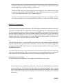
1
2
Put cursor on peak of shortest cycle (1) and click L button; holding down button, drag mouse/cursor to next peak.
Read CPM value in box at upper left screen. Repeat for longest cycle. If the cpm values differ by 20 then code as I
and if less and 20 code as R.
25.8
(25.3 cpm))
42.9
(42.9 cpm)
RESPIRATION RATE IN ALICE 3
FIGURE 10
ARTIFACTS:
a.
Disruptions or artifactual signals of 15 seconds or less duration may be present within an epoch.
Ignore them and code the clean part of the tracing. Movement artifact (X) > ½ an epoch but < 2
epochs can be "smoothed over" if previous and subsequent states are the same. Continue the
surrounding state through the ones with artifact. For example: WXW must be changed to WWW. If
the states are different, code the variables for that portion of the following state that is readable. If
artifacts last more than 2 epochs, score all epochs as awake. If movement results in a state
transition, code the part of the movement that can be read.
b.
Examples of specific artifacts are in Appendix B.
ςΙΙ−50
10/02/95
TABLE 6
Codes to States
States
Individual Parameters
Q (QS)
EEG H, T, M
EOG EMG +
Resp R
BM -, Mouthing, Sucking
A (AS)
EEG F, M
EOG +
EMG Resp I
BM +, mouthing sucking
IS
3 Q + 2 A codes or
2 Q + 3 A codes
e.g. H + - R - = IS
F - + I - = IS
W (AW)
Awake = eyes open, alert or crying
Feeding
Awake is scored W regardless of individual parameter codes. To determine Q, A or IS, you determine
the combination of codes for each epoch and if 4 of 5 (or 5 of 5) are Q parameters, then the state assigned
is Q. If 4 of 5 are A codes, then A is assigned. Any other combination is IS. However, if one or more
variables cannot be used for state determination (eg. EMG and/or eye movements) the rules change to ¾
or ³/3. Some parameters are consistent with both A and Q. It is possible to have ¾Q codes and ¾A codes
for the same epoch. Score these epochs as IS. Code X for movement can be used during hand scoring, it
is not an option on ALICE 3.
ςΙΙ−51
10/02/95
8.
If the state selected differs from that displayed on ALICE 3, use the modification mode and enter your
code. Remember, the smoothing option in 7a applies to ALICE scoring entries.
9.
As coding proceeds, identify and score EEG arousals. See Step 5 Arousal Scoring Procedures for
specific directions.
10.
After all epochs are coded, return to the main menu.
Adding Comments After the Acquisition
(From: Healthdyne ALICE 3, User Manual 1994).
You may add comments after the acquisition and before the reports are printed. In addition, you can also supply a new
start and end time for the study to be included in the printed results. If you want to change a note or a comment in the
Event Table, you may edit it by following the instructions below:
1.
If you want to change the start and/or end times of the study, position the cursor at that time on the All-night
or One-hour screen.
2.
Press <ALT> + "O".
The Observations screen will be displayed.
3.
You can enter comments (up to 40 characters per line) in the 15 observation fields provided. Use the
<ENTER> key or the <TAB> key to move from line to line.
4.
If you want to change the start time, move the cursor to the "Lights Off" field. If you have positioned the
cursor on the new time, press <Insert>. The new time will automatically be entered into the field. You may also
manually enter the new time.
5.
If you want to change the end time, move the cursor to the "Lights On" field. Enter the new end time, or if
you have placed the cursor on the desired new end time press <Insert> and the new time will automatically be
entered.
6.
Press <F10> to exit the screen.
ςΙΙ−52
10/02/95
STEP 5. TRANSIENT AROUSAL SCORING RULES AND
PROCEDURE
DEFINITIONS:
An EEG arousal is an abrupt shift in EEG frequency which may include theta, alpha, or other frequencies
greater than 16 Hz (not including spindles). In infants, alpha frequencies generally will not be present. The
following Rules and Procedures are based on the Atlas Task Force, EEG Arousals: Scoring Rules and
Examples, Sleep, 1992; 15: 174-184. A copy of this reference is included in the Appendix C.
PROCEDURE:
1.
In the state scoring montage (EEG and EMG displayed), examine the EEG for evidence of transient
arousals only during quite sleep and indeterminate sleep.
2.
If the rules are met, place the cursor at the beginning of the arousal and drag the mouse to the end of the
arousal. When you release the mouse, a menu screen will be displayed and you may click on appropriate
arousal type.
3.
Each arousal will be classified as a spontaneous arousal (SA), evoked arousal (EA), apnea termination
(AA), or clinically significant event technician related arousal (TA). To determine the type of arousal
first switch to Alternate Montage 2 displaying the cardiorespiratory signals for the presence of
precipitating respiratory events and then examine the technician notations to determine if there was a
precipitating environmental stimulus for the arousal.
a.
EA - An evoked arousal is preceded by a change in the environment or is induced by the caretaker or
technician.
b.
AA - An apnea termination arousal begins during or immediately after an apnea or hypopnea ≥ 4
seconds in duration.
c.
SA - A spontaneous arousal has no discernable precipitating stimulus.
d.
TA - Arousals induced by caretaker or technician stimulation required for the resolution of a
clinically significant, prolonged cardiorespiratory event.
4.
Scored arousals will appear on the final ALICE event log.
5.
Arousal examples are in Appendix B.
ςΙΙ−53
10/02/95
RULES:
In order to be considered an arousal, the following criteria must be met:
1.
A 10 second period of sleep must precede an arousal. Disregard the arousals that do not meet the
duration criteria of > 3 seconds (you can round up from > 2.5 seconds).
2.
The minimum duration of time between arousals should be 10 seconds. These examples below clarify the
use of this criterion:
a.
1.
2.
3.
4 second arousal - 12 seconds quiet - 4 seconds arousal = 2 arousals.
4 second arousal - 3 seconds quiet - 4 seconds arousal = 1 arousal
4 second arousal - 1 second quiet - 4 seconds arousal = 1 arousal
1.
2.
2 second arousal - 12 seconds quiet - 4 second arousal = 1 arousal
2 second arousal - 4 seconds quiet - 4 second arousal = 1 arousal
(Note: This assumed 4 seconds of quiet EEG preceding the 2 second arousal)
2 second arousal - 1 second quiet - 4 second arousal = 1 arousal
(Note: This assumed 4 seconds of quiet EEG preceding the 2 second arousal)
b.
3.
3.
During quiet sleep (Q) or IS an arousal may occur in the absence of an increase in EMG amplitude.
4.
If movement artifact, delta waves or signal blocking occur within an arousal these are included in meeting
the duration criteria. Blocking must be clearly accompanied by a preceding increase in EMG amplitude.
5.
Isolated sleep state or stage transitions are not scored as arousals.
6.
Although transient arousals have an end-point by definition, there is no specific termination criterion and
duration of arousals is not scored. If the arousal proceeds to an awake state, the arousal ends at the point
the infant is no longer asleep.
ςΙΙ−54
10/02/95
STEP 6. SCORE APNEA EVENTS ≥ 10 SECONDS
NOTE:
ALICE 3 provides a tally of central, mixed and obstructive apnea, which require verification and
possibly additions and deletions.
DEFINITIONS:
Central apnea: Absence of airflow in the CO2 and thermistor channels lasting ≥ 10 seconds and accompanied
by an absence of chest and abdominal respiratory efforts.
Obstructive apnea: Absence of airflow in the CO2 and thermistor channels lasting ≥ 10 seconds with
continued ribcage and abdominal respiratory efforts.
Mixed apnea: Absence of airflow in the CO2 and thermistor channels lasting ≥ 10 seconds with both central
and obstructive components manifest in the ribcage and abdominal channels. The central and obstructive
components must each last at least 3 seconds.
ςΙΙ−55
10/02/95
PROCEDURES:
1.
Retrieve the ALICE 3 event report and identify all events ≥10 seconds.
An event that occurs during sleep, even if the epoch is scored as wakefulness, should be considered as an
event.
2.
Using Alternate Montage 2 follow ALICE 3 procedures to view each 30 second epoch for your selected
infant, beginning after the onset-calibration at the first full minute, on the minute and concluding with the
last full 30 second before the end-calibration. Since there will be a minimum of 8 hours of recording, you
will be scanning at least 960 epochs. Your objective is to evaluate the apnea flagged by ALICE 3 and
identify any missed ones. You may wish to do these two tasks separately or simultaneously.
Alternate Montage 2 consists of ECG, cardiotachometer, ribcage, abdomen, sum (VT), CO2, THERM
(nasal/oral airflow), pulse waveform, O2 saturation, and actimeter.
3.
If an apnea ≥ 10 seconds (central, mixed or obstructive apnea) is present in a certain 30 second epoch,
you first measure the duration. If you consider the duration incorrect, modify the ALICE 3 record by
inserting the correct duration.
Rules for these and other decisions are outlined in Rules (Page VII-58). If you do not agree about the
presence of an apnea, you remove the flagged apnea from the ALICE 3 event table. If you remove an
event because one or more of the respiratory traces are obscured by movement or artifact, add the notation
"uninterpretable" (U) to the comments.
4.
You then proceed to get additional information about the accepted apnea which is to be entered in DCAC
data matrix.
_
Is it central, obstructive or mixed?
_
The time the event began (time of peak measurement began).
_
What was the sleep state when the apnea occurred (A, Q, IS, W)?
_
Duration to whole second of entire apnea and duration of central portion if a mixed apnea.
_
If the apnea precipitated (see Rules) a significant desaturation (SaO2 < 90%), identify the lowest desaturation
value on Form F2 in low SaO2 field.
_
Verify that event precipitated arousals (AA or TA) were identified. Rules about arousals can be found in Step
5, PSG AROUSAL SCORING.
_
Is the apnea preceded by a sigh? Enter sigh (Y/N).
ςΙΙ−56
10/02/95
(From: Healthdyne ALICE 3, User Manual 1994).
ALICE procedures for viewing the display and editing the event table
EVENTS TABLE (Figure 11)
On the Events Table, the information you entered on the Patient Information screen will be shown in a
box in the upper right corner of the screen. The table shows: the event type, sleep state, duration of
respiratory events (as shown on the flow and effort channels), heart rate, saturation data as it relates to
each given event, and the values of the heart and oxygen saturation rates. You can use the following keys
on the main keyboard to navigate through the entire table and review the events you have marked.
<UP> and <DOWN> arrow keys
Highlights an event
<Page Up> and <Page Down> arrow keys
Moves through each screen of the table
<ENTER> key
Selects an event to view on the Raw Data Screen
- key
When placed in the validation column (Val), the
minus sign signifies that you want a specific event
excluded from the final summary report. The event will
not be "highlighted" in the Raw Data.
+ key (<Shift> and +)
When placed in the validation column (Val), the plus
sign signifies that you want a specific event included in
the final summary report.
NOTE: Do not use the keys on the keypad, unless the <Num Lock> key is activated.
Continue to page through the screens of the Events Table until you have analyzed all events to your
satisfaction.
ςΙΙ−57
10/02/95
EVENTS TABLE
FIGURE 11
ςΙΙ−58
10/02/95
OPERATING INSTRUCTIONS
(From: Healthdyne ALICE 3, User Manual 1994).
RAW DATA SCREEN
The Raw Data screen allows you to view more detail and access the waveforms associated with a
specified event. This screen shows the original physiological data recorded on each channel.
1. Move through the screens by pressing the <PgUp> and <PgDn> keys on the main keyboard
(not on the keypad, unless the <Num Lock> key is activated). Using the left or right arrow keys will
cause the program to continuously scroll through the entire study.
2.
To stop scrolling through the study, press the <Spacebar>.
Several boxes will be shown across the top of the screen. These boxes are called context windows, and
they indicate the sleep state at a given time. Each window represents 30 seconds. When you click on a
context window, the screen will move to that point of time into the study. You should verify that what is
shown on the waveforms matches what is indicated in the context window.
As appropriate, you may score respiratory events by utilizing the measurement tool feature of the ALICE
3 System to obtain detailed information about a segment of data. Align the cursor at the point where you
believe an event begins. Drag the mouse across the screen to the area where you believe the event ends
to highlight the data. A white box will appear in the top left portion of the screen.
If the area meets the minimum criteria, another window will be displayed listing each of the types of
respiratory events. Select the appropriate event.
You will notice that the appropriate event has been indicated on the screen by a colored bar.
ςΙΙ−59
10/02/95
RULES:
Central Apnea: Refer to the definition above. The most artifact resistant channel is the CO2; therefore use this
as your primary reference to identify the breaths preceding and following the airflow cessation. The duration of
apnea should be measured from the end of inspiration to the end of the next inspiration ("peak to peak"). If
there is a discrepancy between CO2 duration and THERM duration, use the channel that gives the shortest apnea
duration for determining the beginning and end point of the apnea. Now consult the abdominal channel and
verify whether there was a simultaneous cessation in respiratory movements. If the answer is yes, the apnea can
be considered central.
NOTE 1: Cardiogenic Artifacts can be frequently observed in the CO2 signal. In order not to confuse these
with breaths, check the ECG frequency and ignore those waves that coincide with the heartbeats or
SaO2 pulse waveform. Also, the THERM may give you a clue to the first real breath or resumption
of breathing after an apnea.
NOTE 2: A more accurate estimate of apnea duration is obtained by measuring the interval between the end of
inspiration and the next onset of inspiration. Healthdyne uses this interval in their ALICE 3
algorithm. For the human eye peak to peak detection is easier and this strategy is selected for the
CHIME Monitor tracing and incorporated in this protocol as well. As a result, the duration values
may have to be altered for each apnea.
NOTE 3: There is almost one second lag between the CO2 signal and other respiratory signals. The term
"simultaneous" presupposes that you discount that 1 second delay.
NOTE 4: In some circumstances only the THERM will be available. You can use this channel as an
alternative to CO2. The beginning and end of the apnea must be timed on the same channel.
NOTE 5: If the preceding or subsequent breath is broad, without a peak, identify the middle of that breath as
the peak. If breaths are more easily identified on the THERM channel, time the apnea using this
channel.
NOTE 6: The first breath or few breaths following a central apnea may be paradoxical with reduced airflow.
However, the central apnea terminates at the first effort, even if the breath is out of phase.
NOTE 7: The first breath following a central apnea may be paradoxical without airflow (obstructed breath) yet
this obstructed component may not last the 3 seconds necessary to meet criteria for mixed apnea.
The termination of central apnea is timed with the return of respiratory efforts.
NOTE 8: Both the CO2 and airflow channels are subject to displacement artifact. They also have different
time lags or offsets from the respiratory effort channel. The beginning and end of apneas must be
timed on the same channel and you are to use the channel that gives you the shortest apnea duration.
NOTE 9: If both the CO2 and THERM are displaced, examine the respiratory effort channels for any cessation
of effort ≥ 10 seconds. In this instance, you may use the RC or AB channels to score central apneas
based on time from peak of last effort to peak of first effort on the same channel.
ςΙΙ−60
10/02/95
Note the different strategy for identifying “peak to peak” inspiration on the CO2 channel vs the respiratory effort and
thermistor channels.
ςΙΙ−61
10/02/95
STEP 7. SCORING OF HYPOPNEA
This protocol utilizes the same ALICE 3 event log and the ALICE 3 procedures that are used to verify and
characterize apneic events ≥ 10 seconds. See Step 6.
DEFINITIONS:
Central hypopnea (CH): A 50% decrease in the amplitude of the thermistor channel lasting 10 seconds
or more with the ribcage and abdominal movements in phase. In order to qualify, one of two additional
criteria have to be fulfilled: the event must be followed by a drop in oxyhemoglobin saturation (SaO2) of
4% or more or an arousal confirmed by EEG. See Arousal Protocol, Step 5.
Obstructive hypopnea (OH) (partial obstruction): A 50% decrease in the amplitude of the thermistor signal
lasting 10 seconds or more with ribcage and abdominal movements partially or completely out of phase. In
order to qualify one of two additional criteria must be fulfilled: the event must be accompanied by a drop in
SaO2 of 4% or more or an arousal confirmed on EEG. See Arousal Protocol, Step 5.
PROCEDURES AND DECISION MAKING RULES:
1.
Choose Alternate Montage 2 which consists of ECG, cardiotachometer, ribcage and abdominal
movements, sum (VT), CO2, THERM, pulse waveform, SaO2 and actimeter.
2.
Retrieve the ALICE 3 event log. ALICE 3 will identify hypopnea based on drops in THERM of 50% or
more. The objective is to verify these drops and to determine whether either one or both of the other two
criteria are present as well. If not the event should be deleted. Hypopneic events fulfilling the criteria
that ALICE 3 failed to identify are to be added.
a.
Begin by scrutinizing each flagged hypopnea. Verify the 4% drop in SaO2. In order to accept the
validity of the SaO2 signal, there should be at least 3 acceptable pulse waves. If artifact prevails, this
latter criterion is not fulfilled and the SaO2 cannot be used to accept or reject the hypopnea. The
SaO2 drop should occur either during the hypopneic event or within seconds after the termination of
this event.
Check whether a previously scored arousal is contingent on this event. An arousal is considered
contingent if it occurs during or within 5 seconds after the termination of the hypopneic event. If at
least one of the two or both criteria is not fulfilled remove the flagged hypopnea from the ALICE 3
event table by marking it with a minus sign. Hypopnea related arousals during AS (A) will need to
be identified during hypopnea scoring as they are not included in sleep state scoring.
b.
If you agree with the ALICE 3 decision, measure the duration. If you disagree with the value in the
table, rectify by inserting the correct value. The beginning of an hypopneic event is defined by the
ςΙΙ−62
10/02/95
peak of the last "full" breath, that is the breath before the amplitude dropped by 50%. The
termination of an hypopneic event is defined as the peak of the first breath with an amplitude ≥50%.
c.
Then consult the ribcage and abdominal channels to determine if it is central or obstructive
hypopnea. If these two channels are in phase, it is a central hypopnea. A (+) will confirm that you
agree the event is a central hypopnea.
If these two channels are not in phase, it is an obstructive hypopnea. This can be scored as a user
defined event. Use the (-) sign to remove the central hypopnea. Sweep the cursor across the event.
When you release the mouse button, the menu of both ALICE 3 and user defined event will appear.
Click on obstructive hypopnea and the event will be added to the event table.
NOTE: It is possible that movements prevent accurate identification of central and especially
obstructive hypopnea. Check sleep states to see whether the infant was awake. If so, delete the
hypopnea. If the infant was asleep, mark the hypopnea as uninterpretable on the event table. This
needs to be done by hand.
d.
After the ALICE 3 identified hypopneic events have been verified, the recording has to be scanned
for possible omissions. Steps (a) through (c) have to be followed and additional events must be
added to the event table.
e.
Enter hypopnea results as necessary.
ςΙΙ−63
10/02/95
(From: Healthdyne ALICE 3, User Manual 1994).
Saving Your Modifications
When you have finished Scoring the entire study and the events have been validated, you should save your modifications.
1.
Press <ESC> from within the viewing program to access the menu.
2.
From the menu, select to "Exit to main menu".
3.
From the Main Menu, select the “Backup current patient” option.
The back-up process will occur automatically. When the process has been completed, you may proceed to display or print
your results.
STEP 8. REMOVE ARTIFACT IN SPECIFIC CHANNELS IN ORDER TO ALLOW
FOR AUTOMATED ANALYSIS AND COMPILATION OF SUMMARY
VARIABLES
Elimination of Spurious Oximetry Data
The pulse waveform indicates the quality of the oximeter data. A rounded, upgoing signal should be present for
each QRS complex on the ECG although the pulse waveform will be slightly delayed. Any significant decrease
in amplitude may indicate a concomitant decrease in SaO2 reliability.
When the pulse signal identifies unreliable data, the SaO2 signal must be eliminated for that segment and 5
seconds beyond. Using the mouse, position the cursor arrow on the left-most area of the bad pulse signal.
Depress and hold the left button on the mouse. Move the mouse a small distance to the right so a narrow
segment of the screen (approximately 1 mm) is defined by two parallel, narrow black lines running from top to
bottom. Release the button on the mouse. The area between the two lines will be black, and a menu will
appear on the left side of the screen. Use the mouse to select "Start Highlight Period" by moving the cursor to
this block on the menu and pressing the left button on the mouse one time. Now the menu and the highlighted
area disappear and a green box comes up in the lower margin of the screen that says "highlight: time ?" Move
the cursor arrow to the end of the bad area and highlight one millimeter area as before. When the menu
appears, select "End highlight period". The green box at the bottom of the screen now shows the time for the
beginning and end of the bad area. Now move the cursor arrow to the left margin of the screen and position it
over the title SaO2. Click on right mouse button (ESC). On drop down menu, select "ADD FAIL PERIOD".
You should see a grey bar cover the period you selected.
ςΙΙ−64
10/02/95
Elimination of Spurious End-tidal CO2 Data
When the end-tidal PCO2 (PETCO2) signal becomes artifactual, it should be removed from calculations for the
overnight study. The PETCO2 signal is subject to artifact, usually due to displacement or plugging of the nasal
catheter leading to falsely low values. Accurate PETCO2 signals are characterized by a smooth, end-expiratory
plateau, with small variations in amplitude from breath to breath. With rapid respiratory rates, a smooth peak is
sometimes observed rather than a plateau. PETCO2 readings should be considered artifactual under the
following circumstances:
a.
If the oral-nasal thermistor signal shows stable baseline flow, but the PETCO2 amplitude is reduced from
baseline by one-third or more, then that portion of the PETCO2 should be considered artifact, and the data
should not be included in summary calculations.
b.
If the technician notes that the catheter has been displaced or plugged and replaces the catheter, the
affected data preceding the catheter replacement should be discarded.
c.
If the signal is disrupted from movement secondary to catheter displacement and the signal spontaneously
returns to the previous baseline, the affected data should be removed. Obstructive sleep apnea can occur
in association with movement, so this data should be evaluated carefully before it is removed from the
calculations.
Cardiac Signals
Observe the cardiac rate on ALICE 3 raw data. If the rate drops precipitously due to a loose electrode or an
artifact for at least 3 beats remove the signal. Healthdyne will consider adding median heart rate values which
protects against isolated erroneous data.
STEP 9. UPON COMPLETION OF ALICE 3 SCORING,
PRINT OUT FINAL SUMMARY REPORT
STEP 10. COMPARISON OF ALICE 3 and CHIME MONITOR
EVENTS
The CHIME DCAC will be responsible for comparing the scored events from both the ALICE 3 system and the
CHIME Monitor.
Study sites will not be responsible for completing the following items. They are included here for
documentation purposes only.
ςΙΙ−65
10/02/95
Standard Event Scoring; also see Step 6 and Step 7.
1.
Obtain the summaries of the results of scoring of events for both ALICE 3 and CHIME Monitor.
2.
For each event scored on ALICE 3 that meets the CHIME criteria, determine if there was a corresponding
CHIME Monitor event that occurred during the same period.
AT ALICE 3
3.
Based on CHIME Monitor scoring summary, use ALICE 3 to review all events that included low
amplitude deflections.
4.
Locate each event and evaluate the airflow signals to determine the presence or absence of airflow for
each low amplitude deflection. Note the total number of low amplitude deflections with airflow.
5.
If any events were scored as genuine on CHIME Monitor scoring but not identified during ALICE 3
scoring, these should be located on ALICE 3 and rescored to accurately characterize the events.
Following rescoring a new scoring summary should be printed out.
AT CHIME MONITOR BASE STATION
6.
For each ALICE 3 event utilize the CHIME scoring software to add the results of ALICE 3 scoring to the
corresponding CHIME event. Note that there are special fields in the CHIME Monitor software that
allow input of the results of the ALICE 3 scoring. Also note that it is possible that a genuine event scored
on ALICE 3 may have been labeled FALSE on original CHIME Monitor scoring. In these cases the
ALICE 3 fields should still be added.
7.
If an ALICE 3 event was not detected by the CHIME Monitor, use CHIME Monitor software to add the
event to the CHIME database.
8.
Print out new CHIME Monitor scoring summary.
ςΙΙ−66
10/02/95
Appendix A
Several components of the data acquisition protocol are in the final stages of testing; these include the DAS,
thermometer and eye movement sensor. Descriptions of these components are in this appendix for information
purposes only. When the components are ready to be integrated into the acquisition procedure, an addendum to this
PSG protocol, with implementation details, will be distributed to each site.
CHIME PSG Data Acquisition System
The CHIME Data Acquisition System requires different connections between study subjects and the ALICE 3 PSG
monitor than would be used for a straight ALICE 3 PSG. The principal difference is the use of the D.A.S. amplifier
as the interface between the subject and the electronic equipment as opposed to the Calvin unit that is used when the
ALICE 3 monitor is used alone. The D.A.S. amplifier is connected to the Calvin by means of a cable that connects
between the "input device" connector on the Calvin unit and the "Calvin" connector on the back of the D.A.S.
amplifier. The "auxiliary input" connectors on the side of the Calvin unit labeled 1, 2, 3, 4, 5 get connected to the
five connectors labeled "aux" immediately under the Calvin connector on the D.A.S. amplifier. Please note that the
numbering of these connectors on the D.A.S. amplifier is not sequential and it is important that the small telephone
wire connection be made between connectors of the same number on the Calvin unit and on the D.A.S. amplifier
unit. Special cables with small black plastic connectors on each end are provided with the D.A.S. unit to connect the
eye movement and temperature channels between the D.A.S.. amplifiers and Calvin. Connect one end of the one
cable to the connector labeled "Spare 1" on Calvin and the other end to the connector on the back of the D.A.S. unit
labeled "eye out". Similarly, connect the second cable to the connector labeled "Spare 2" on Calvin with the other
end connected to the connector on the D.A.S. amplifier unit labeled "temp out". This completes connecting the
D.A.S. to the Calvin unit.
Connecting the D.A.S. Amplifier Unit to the Patient
The patient box normally connected to the "input device" connector on Calvin is now connected to the connector
labeled "patient box" on the D.A.S. amplifier unit. The cable from the NIMS monitor that normally is connected to
Calvin through a special set of wires that went into the "auxiliary input" is now connected to the D.A.S. unit at the
connector labeled "NIMS". A special cable has been provided with the D.A.S. unit to connect the output from your
capnometer to the input connector on the D.A.S. labeled "CO2 in". Similarly, a cable from the special CHIME eye
movement sensor connects to the connector on the D.A.S. amplifier labeled "eye in". The special CHIME
temperature monitor connects through its cable to the input labeled "temp in". The patient box and the capnometer,
eye movement sensor, and temperature monitor are all connected to the study subject in the same way as is done
with the ALICE 3.
Connecting the D.A.S. Amplifier Unit to the D.A.S. Computer
The D.A.S. amplifier unit has an output connector labeled "D.A.S." and this gets connected to the D.A.S. computer
by means of a cable provided with the D.A.S. unit. The cable connects to the unmarked connector on the back of the
computer near the right when facing the back of the computer. This is the only connector on the computer that will
accept the D.A.S. cable, so do not try to force the cable into another connector on the computer where it will not fit
properly. The D.A.S. amplifier must also be connected to the power supply using the connector labeled "12 VDC",
and the power supply is plugged into the standard electrical outlet.
ςΙΙ−67
10/02/95
This completes the procedure for connecting the D.A.S. unit and computer to the ALICE 3 system. It is important to
note that the connections between Calvin and the ALICE 3 unit remain the same as they were when the D.A.S. unit
was not used. ALICE 3 will not work properly if these connections are not correctly made.
Operating the D.A.S. Computer
Although the D.A.S. system is connected between the subject and ALICE 3, it does not interfere with any of the
normal ALICE 3 functions with the exception of measuring electrode impedance. Thus, it is possible to use ALICE
3 without using the D.A.S. computer by merely using the connections described in the previous section and
switching the D.A.S. amplifier unit on by means of the red switch on the top of the unit. You will know that the unit
is switched on by the light that shines from within the switch. The only ALICE 3 function that does not work with
the D.A.S. system connected is the measurement of the EEG electrode impedances while collecting data (by
depressing <F> on the ALICE 3 keyboard). We had to sacrifice that function to enable the D.A.S. system to collect
data not only for ALICE 3 but also for the D.A.S. computer. A small electrode impedance meter has been designed
at the CTOC to allow electrode impedances to be measured independent of the D.A.S. or ALICE 3 monitor.
To begin collecting data, ALICE 3 should be set up in the usual manner. Once it has been determined that ALICE 3
is collecting the data as desired by the investigators, the D.A.S. computer can be started. This is done by first
switching on the computer and waiting until the C prompt (C:\>) appears. To start the program type "das" and push
the <Enter> key. A blue screen should appear that says "Global Lab". At this point type the letter S followed by the
enter key and a small menu will appear at the center of the top of the screen. From this menu choose "A/D Module"
by moving the highlighted band using the down arrow cursor key or typing the letter A. We are now in the data
acquisition mode of the software and a new window will appear at the upper left corner of the screen. Choose the
entry on this menu labeled "Load" and a menu that asks you to type in the name of the set-up program for the PSG
will appear. At this point you should type in "CHIME" followed by the <ENTER> key, and this will load the
CHIME montage for the data acquisition system. Once this is completed the small window in the upper left-hand
corner of the screen will reappear. Now it is necessary to name the file where the data will be stored on the
computer's hard disk. Select the "Edit" item from the menu and a new large, complicated window will appear. At
the lower right-hand corner of this window is an entry called "Filename". A name which is usually "CHIME.OUT"
will appear at this point, and you should use the mouse to position the cursor (small white arrow) at the "C" and
press the left mouse button. Now you can type the name of the storage file so that it replaces the "CHIME.OUT" in
that listing. The conventions for naming the CHIME storage file follows. After you have typed in the filename
move the cursor with the mouse to the button labeled "OK" and depress the left mouse button. The screen will
return to the small window in the upper left-hand corner.
Now choose the acquisition mode by typing "A". A new small window will appear under the word "Acquisition" at
the top of the screen. The first item in this menu is the word "Go" and it should be highlighted in white. If for some
reason it is not highlighted, use the up or down arrow curser keys to move the highlighted area to the word "Go". To
start acquisition push the <Enter> key and the data acquisition screen will appear. This consists of a series of 20
horizontal white lines on a black background. To actually start acquiring data you must push any key on the
keyboard, and you will see the waveforms being collected on the screen. These signals will be flashing by too fast to
be able to be viewed and understood, but this display can be used to indicate that data is being collected. At the
bottom of the screen will be a blue bar with the words "Acquisition Running". If you do not see this, the
acquisition system is probably not running correctly and you need to repeat the previous steps to make sure that data
is being acquired.
The D.A.S. computer need no further attention until the study ends.
ςΙΙ−68
10/02/95
Ending a Data Acquisition Session
Once the PSG study has been completed, you can stop the data acquisition system by pushing the escape <ESC>
button on the keyboard. The blue bar at the bottom of the screen will say "interrupted after (number) scans!
Save used buffers to disk?" and below that are listed a highlighted "Yes" or "No". If the "Yes" is highlighted and
you wish to save the data push the <Enter> button. If you do not wish to save the data move the highlight to the
"No" using the right arrow key, and then push the <Enter> key. Once this selection is made, data acquisition is
complete. To exit the program you must push the S key to bring up a new menu under the word "System" at the top
of the screen. The last item on this menu is "Exit" and you can either highlight this by pressing the <Down Arrow>
key five times or typing the letter E. Once the exit is highlighted, press the <Enter> key and you will return to the C
prompt.
Eye Movement Sensor Test
Before use, the batteries should be tested. This is done by depressing the battery test button (labeled
"press to test") and holding the button down for at least three seconds. The battery test light should come
on and remain on for the entire duration of the time the button is depressed. If the light comes on as the
button is depressed, but its intensity decreases and eventually the light goes out while the button is still
depressed, there is not enough power in the battery to operate the sensor for the PSG, and the batteries
need to be replaced. If the light does not come on at all once the button is depressed, the batteries need to
be replaced. Battery lifetime is approximately 90 hours for fresh batteries. Thus, you can expect to
change batteries after seven 12-hour PSG studies. If the batteries need to be replaced, follow the
instructions in the "replacement of batteries" section of these instructions.
Note: Replacement of Batteries
The following steps should be used in replacing the battery (AA, any brand).
1.
Unscrew the four screws in the corners of the front panel of the CHIME eye movement sensor
electronic box.
2.
Lift the front panel from the box, recognizing that it is connected to the batteries by two wires. Be
careful not to break these wires.
3.
Remove the old batteries from the battery clip, noting their orientation. Replace these batteries with
fresh batteries in the same orientation. A "+" is indicated on each side of the battery clip to show the
orientation of the positive battery terminal. Make sure that the batteries are firmly installed in the
battery holder.
4.
Re-assemble the front panel on the box. You might want to press the battery test button to make
sure that the light lights before replacing the screws in the four corners on the front panel. This
completes the battery replacement procedure.
Eye Movement Sensor: The sensor should be placed over the orbit of one eye. If the infant is
placed in the lateral position then place the sensor on the contralateral side. Non-allergenic tape
should be used to hold the sensor in place, and the lead wire should also be taped to the cheek so that
strain on the wire will not pull the sensor off the eye.
ςΙΙ−69
10/02/95
Connect the sensor cable to the input connector on the electronic box and lock the plug in place by
twisting the clip located on the plug near the prongs, so that it engages the clip on the socket and
keeps the plug from accidentally coming out of the socket.
Connect the output cable to the output connector on the electronics box, and connect the other end of
the cable to the input marked "EYE MOVEMENT" on the CHIME data acquisition unit or "SPARE
1" on the Calvin box of the ALICE 3 PSG machine (Figure 8.)
Switch the eye movement sensor box on by flipping the toggle switch to the "on" position. Within a
few seconds recordings of eye movement should be seen on the "eye" channel of the PSG computer.
CHIME PSG Thermometer
This instrument consists of the electronics package itself, a thermistor for measuring skin temperature,
and a thermistor for measuring air temperature. The skin temperature thermistor consists of a metal disk
at the end of a flexible white wire connected to a longer, more robust gray wire with a plug at the other
end. This plug should be connected to the connector marked "SKIN" on the front panel of the instrument
directly beneath the digital display. Make sure that the connector is pressed all the way into the socket so
that good contact is established. The air thermistor is located within a metallic cylindrical cage with oval
openings on the sides. It also has a gray wire with a plug on the end that should be connected to the
socket on the electronic instrument front panel marked "AIR'.
The output signal from this instrument is available at the smaller connector marked "OUT" on the righthand side of the front panel. A special cable that connects between this connector and the CHIME data
acquisition amplifier unit is provided with the instrument. One end of this cable should be plugged into
the connector marked "OUT" and the other goes to the data acquisition amplifier to the connector marked
"TEMPERATURE IN".
The CHIME PSG thermometer is operated on battery power and does not require any other connections
for power or information transfer. Since it is battery powered, it is important that the power switch is left
in the off position when the thermometer is not used so that battery energy can be conserved.
Instructions for Use with PSG
The following steps should be carried out in using the thermometer for PSG studies.
1.
Make sure that the thermistors and interface cables are connected as described above.
2.
The skin thermistor should be placed on the infant's abdomen in the right upper quadrant over the
liver (See Section D.6.j. Application of Electrodes.) The metal side of the thermistor should be in
contact with the skin. The thermistor should be held in place using non-allergenic tape. A second
piece of tape should secure the lead wire to the infant so that there is no tension on the thermistor
itself. Such tension could cause the thermistor to loosen from the skin and give an erroneous
temperature.
ςΙΙ−70
10/02/95
3.
Place the air temperature thermistor over the infant's head 30 to 70 cm above the face. The method
of securing this thermistor will be dependent upon the arrangements used at the particular center
where the study is being carried out, but it is important that the thermistor be in a position where it
will not be bumped by care-givers during the study.
4.
The instrument can then be switched on using the power switch located under the selector knob on
the front panel. The switch is in the "on" position when the toggle is pointing upward, and the
power light (PWR) is lit. This is not a bright light, so it may be difficult to see in a bright room. If
this light is not lit, it is necessary to change batteries before proceeding any further. Instructions for
this are given in the next section.
5.
The selector knob is used to check the calibration of the instrument. After the instrument is
switched on, the selector should be set to 20. This is done by pushing in on the knob and turning
until the white pointer points to the number 20 on the panel. After a few seconds the digital
indicator on the panel should read 20.0. Due to the least significant figure error of this type of
instrument, the panel may indicate 20.1 or 19.9, but this will be within the accuracy of the
instrument. If a number that is not close to 20 appears, the instrument is not working correctly, and
you should contact the CHIME engineer on call. Now move the selector switch to the position
labeled "30". The panel meter should ideally give the reading of 30.0, but 29.9 and 30.1 are equally
acceptable. Now move the selector switch to the number 40, and the panel display should indicate
39.9, 40.0, or 40.1. This completes the calibration check, and the selector switch should be returned
to the position labeled "OP". The instrument is now ready for operation.
6.
The switch to the immediate right of the skin thermistor connector determines whether the
instrument is measuring the air temperature and the skin temperature (the "A/S" position of the
switch) or just measuring the air temperature (the "A" Position). Choose the position that you will
use for the PSG study. It is recommended that the A/S position be used.
7.
The digital display on the front panel will now show the temperature of either the air probe or the
skin probe. Each is displayed for 20 seconds. When the instrument is set up for both air and skin
temperature the first 20 second segment after it is turned on gives the air temperature, followed by
20 seconds of the skin temperature and repeating. Although it is difficult to know which is which by
looking at the digital display, it will be quite clear on the ALICE 3 screen, since the skin temperature
will be at a higher level than the air temperature.
ςΙΙ−71
10/02/95
Replacement of Batteries
The CHIME PSG thermometer is operated on battery power. Periodically these batteries will need to be
replaced. It is time to replace the batteries when upon turning on the instrument the red "PWR" light fails
to illuminate even though the numbers on the digital read-out are functioning. If the batteries need to be
replaced, the following steps should be taken.
1.
Batteries are located in a compartment on the bottom of the CHIME PSG thermometer. The
compartment cover can be identified by the word "OPEN". To open this cover, press down over the
"OPEN" label and slide the cover toward the rear of the instrument.
2.
Four AA size alkaline batteries are housed in the battery compartment. All four should be changed.
It is sometimes difficult to remove the first battery, but this can be done by sliding a small
screwdriver between the first battery and the back of the case and gently prying the battery up from
its holder. It is relatively easy to remove the remaining batteries without the screwdriver.
3.
Replace the batteries making sure that the positive end (marked "+") corresponds with the "+" sign
written on the bottom of the battery compartment at each battery position. Note that each battery is
in the opposite position from the one to which it is adjacent. Make sure that batteries are firmly
seated in the battery compartment and replace the compartment cover by sliding it in from the back
of the case until it snaps in place.
ςΙΙ−72
10/02/95
Appendix B
Table of Contents
CHIME MONITOR PSG CARTRIDGE PARAMETERS
QUALITY OF INDIVIDUAL PSG CHANNELS
PSG SIGNAL QUALITY FORM
FORM F1: CHIME Polysomnography Checklist
EXAMPLE OF INSTRUCTIONS TO PARENTS
STATE CODING PARAMETER SUMMARY (5/1/95 VERSION)
WAVEFORM EXAMPLES *
Sleep State
Q (Quiet Asleep)
Preterm 34-37 wks PCA 1,2
Preterm/Term 38-50 wks PCA
Infants ≥ 50 wks PCA
Waveforms by number
3,4,5,618
8,9
A (Active Sleep)
Preterm 34-37 wks PCA 10
Preterm/Term 38-50 wks PCA
Infants ≥ 50 wks PCA
11,12,13
14,15
I (Indeterminate Sleep)
Preterm 34-37 wks PCA 16
Infants ≥ 50 wks PCA
7,19
W (Awake)
All age groups
20,21,22
Sleep State Parameters
EM
+ LEOG/REOG
- LEOG/REOG
slow eye movements
5,7,8,10,14-16
1-4,4-6,9,18,19
EEG
F
M
T
H
10-13
7,9
1,2,3
4-6,8,9,14-16,18
EMG
+
-
3,5,12
1,2,4,6,7-11,13-19
Resp.
ςΙΙ−73
10/02/95
R
I
2-6,8,9,16,18
7,10-15,19
BM
+
-
10,12,14,15
1-9,13,16-19
EVENTS
Waveforms By Number
Apnea
Central Apnea
Obstructive Apnea
Mixed Apnea
25
26
Hypopnea
Associated Desaturation of 4%
Associated Arousal
29
Periodic Breathing
26-28
Arousal
SA
AA
24
23
CO2 Purge Artifact
31,33
Movement Artifact
32
SaO2 Removal
30
ςΙΙ−74
10/02/95
* In order to reduce the number of sample waveforms, some may contain examples of several things such as overall state, an
apneic event, and eye movement as defined by the eye movement sensor. Each waveform is numbered to help you move
through the cross-referencing numbers. Contents are arranged by waveform type by waveform number. As new examples are
added new numbers will be added.
ςΙΙ−75
10/02/95
CHIME MONITOR PSG CARTRIDGE PARAMETERS
For sites where PSG staff initializes cartridge: At other sites CHIME staff will provide prepared PSG and new
home cartridge for each PSG.
ςΙΙ−76
Initialize the CHIME cartridge for PSG Use.
Enter Infant's Information:
1.
2.
3.
4.
5.
6.
For Name, enter infant's "Event Record Label" (ERL). i.e., tokj12003121893
Enter infant's Date of Birth (mm/dd/yy).
Enter infant's ID# (5-digit Study ID#).
Enter infant's Sex (M/F).
Address information may be left blank.
Enter in Comments: CHIME monitor S/N and Cartridge S/N used during the PSG.
Enter Monitor ALARM & RECORD Settings:
1.
2.
For APNEA, set "Alarm" to 90 seconds; and "Record" to 16 seconds.
For BRADYCARDIA, set "Alarm" to -240 (Enter a negative value to disable the alarm.) Set "Record" to 80
(<44 wks PCA) or 60 (>44 wks PCA).
3.
For Hypopnea, Labored Breath, Rapid Breath, Tachycardia, and O2 Sat: Enter negative values to disable the
alarms.
4.
"Event Waveform Buffers" values remain the same for all infants. Buffers should display the following
values: 75, 30, 400, 25, 0, 1, and 3. "Continuous Record" should be set to ON (check mark).
APNEA
Hypopnea
Labored Breath
Rapid Breath
BRADYCARDIA
Tachycardia
O2 Sat
ALARM
RECORD
Event Waveforms Buffers
90
-25
-9.0
-240
-80
-60
-240
-50
16
-25
-9.0
-240
80 (<44 wks PCA)
60 (>44 wks PCA)
-240
-50
⋅Pre-Record (sec)
⋅Post-Record (sec)
⋅Calibration Values
Def. Quan. Val.
⋅Min. Acc Vol.
⋅Periodic Recording
Starting Hour
⋅Interval (hours)
⋅Duration (minutes)
⋅Continuous Record
ON = Check Mark
OFF = No Check Mark]
5. Note: Monitor will ALARM for Band and Lead Disconnects and asystole (slow heart light).
ςΙΙ−77
75
30
400
25
0
1
3
ON
Quality of Individual PSG Channels:
Infant's Name:_____________________
Study ID:__________________________
Date:______________________________
Quality of Individual PSG Channels:
CHANNELS
1
R-EOG
2
L-EOG
3
C 4 - M1
4
C 3 - M2
5
O2 - M1
6
O1 - M2
7
Chin
8
Position
9
Temp
10
ECG
11
Cardiotachometer
12
Impedance
13
RC
14
Abdomen
15
Sum
16
CO2
17
CO2 Number
18
Thermistor
GAIN SET
AMPLITUDE
BOX
IMPEDANCE
ςΙΙ−78
ALICE
IMPEDANCE
COMMENTS
10/02/95
19
Oximeter Pulse
Waveform
20
O2 Saturation
21
Actimeter
ςΙΙ−79
10/02/95
REFERENCES
1.
ALICE3. Manual of Operations. 1994 version.
2.
Anders, T. The infant sleep profile. (1974). Neuropadiatre, 5, 425-442.
3.
Anders, T., Emde R., Parmelee A. (Eds). A Manual of Standardized Terminology, Techniques and Criteria for
Scoring of States of Sleep and Wakefulness in Newborn Infants. UCLA Brain Information Service/BRI
Publications Office, 1971.
4.
Hoppenbrouwers, T. (1992). Polysomnography in newborns and young infants: Sleep architecture. Journal of
Clinical Neurophysiology, 9, 32-47.
5.
Rechtschaffen, A., Kales A. (eds). A manual of standardized Terminology, Techniques and Scoring System for
Sleep Stages of Human Subjects. National Institutes of Health Publication No. 204, U.S. Government Printing
Office, Washington, D.C., 1968.
6.
Stockard-Pope, J.E., Werner, S.S., Bickford, R.G. Atlas of Neonatal Electroencephalography, 2nd ed., New York:
Raven Press, 1992.
7.
ASDA Task Force. EEG arousals: Scoring rules and examples. A preliminary Report from the Sleep Disorders
Atlas Task Force of the American Sleep Disorders Association. Sleep, 1992, 15, pp. 174-184.
ςΙΙ−118
10/02/95
Appendix D
Approved Supply List
Parameter
Sensors
Recommended Brand
EEG
Gold cup electrodes, 48"
leadwire w/ hole, 10/box, specify
male pins (not female safety
jacks
Elefix Cream or Ten-20
Grass E5GH
Gold cup (same as EEG) with
paste or Contour IB.
Elefix Cream or Ten-20
Grass
Miniature biopotential electrodes
(AgAgCl)
Kit includes 5 electrodes with
60" leads, 2 60mg tubes of
electrolyte gel and 200 adhesive
washers.
Order standard male jacks.
Gel from Gereonics is Sigma
Gel (Parker)
Gereonics
450318
Respiration (Effort)
Respiband Plus Bands. 24" (set
of two) or 15" (set of two)
Model 107-007-24 or 107-00715
NIMS
Respiration Airflow
(thermistor)
Healthdyne, neonatal nasal
thermistor (with supply of
double stick adhesives) (catalog
No. 6210)
Healthdyne
ECG
Contour S30 1B. Conductive
solid gel ECG neonatal/pediatric
disposable Ag/AgCl electrodes.
(45/pouch)
and
Jenson Premie Solid Gel Cloth,
Snap Ag/AgCl Reusable
Electrodes P/N: A-3501
(30/pouch); P/N: A-3502 or P/N:
A-3503
Contour
Medical Technology, Inc.
Ohmeda SoftProbe (Reusable)
7900 - 222/F
Ohmeda
EOG
Submental EMG
SaO2
ςΙΙ−125
Nihon Kohden/D.O. Weaver
or Contour IB
Nihon Kohden/D.O. Weaver
DM Davis also supplies adhesive
collars (washers)
Jenson Medical International
10/02/95
General
Skin Preparation - Omniprep 5oz.
D.O. Weaver & Co.
Tape - Micropore
3M *
Tape - Transpore
3M *
Tape - Coban
3M *
Cotton Tipped Applicators, 100 - 6 inch
*
CO2 (O2) Salter Labs, one No. 4701F, Infant (Divided
Cannula) Oxygen delivery CO2 sampling nasal cannula
Salter Labs *
Bandage - Kerlix, Disposable (single pt. use)
*
Kendall Conform Stretch Bandage, 2 or 4" X 4.1 yd.
stretched. (Kling, elastic gauge)
*
Optical disks (Maxtor) OC-800 or equivalent
City Computer &
Supply
Arm Restraints - Pediwrap w/o thumbhole #201 neonatal or
pediatric #203
The Medi-Kid Co.
Posey Oximeter Probe Wrap 6554
Posey*
* These should be available through your medical center purchasing or central supply departments.
ςΙΙ−126
10/02/95
Vendors
City Computer and Supplies
271 Schropp Ave.
Akron, OH 44312
1-800-759-6868
Contour Medical Technology, Inc.
144 Southway Blvd.
La Veryne, TN 37086
1-800-851-8184
Fax: 615-793-6998
DM Davis Inc.
215 West 90th St.
NY, NY 10024
PH: 212-787-8519
Gereonics, Inc.
4650-143 Dulin Rd.
Fallbrook, Calif. 92028
Call toll free: 1-800-654-6266, 8-3pm PST
PH: 619-731-9003
FAX: 619-728-4640
Astro-Med
Grass Instrument Co.
101 Old Colony Ave.
P.O. Box 516
Quincy, MA 02269-0516
PH: 617-775-0002
Fax: 617-773-0415
Jenson Medical International
P.O. Box 8114
The Woodlands, Texas 77387
1-800-992-5487
PH: 409-539-5544
FAX: 409-539-5533
The Medi-Kid Co.
P.O. Box 716
Nueva, CA 92567
PH: 909-928-9528
FAX: 909-928-1223
Neuro Supplies Inc.
86 Boston Rd.
Waterford, CN 06385
1-800-638-7693
Nihon Kohden America
1-800-325-0283
NIMS
1840 West Avenue
Miami Beach, Florida 33139
1-800-654-6467
Salter Labs
100 W. Sycamore Rd.
Arvin, CA 93203
D.O. Weaver & Co.
565-C Nucla Way
Aurora, Co 80011
ςΙΙ−127
10/02/95