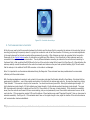
1
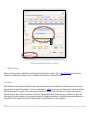
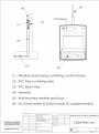
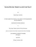
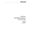
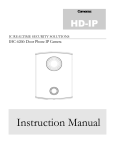
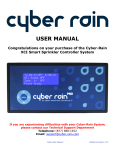
Cyber-Rain Long Range XCI Smart Sprinkler Controller Installation Manual 1|Cyber-Rain Long Range XCI Smart Sprinkler Controller Installation Manual Please see a Cyber-Rain Certified Installer or Licensed Professional Installer for Cyber-Rain Long Range Controller Installation. Table of Contents Pre-Installation Check-List ....................................................................................................................................................................................................................... 4 Cyber-Rain and Installation Components ................................................................................................................................................................................................ 5 Cyber-Rain Long Range Controller ................................................................................................................................................... 6 Access Point ................................................................................................................................................................................. 7 Antennas ...................................................................................................................................................................................... 7 Whip Antennas ........................................................................................................................................................................... 8 Long Range Omni-Directional Antennas ......................................................................................................................................... 8 Patch Antennas .......................................................................................................................................................................... 9 Coaxial Cables ............................................................................................................................................................................ 10 Installation ............................................................................................................................................................................................................................................. 11 1. Install Central Antenna .......................................................................................................................................................... 11 Outdoor Omni-Directional Antenna ............................................................................................................................................. 11 Indoor Omni-Directional Antenna................................................................................................................................................ 13 Desktop Omni-Directional Antenna ............................................................................................................................................. 13 Connecting and Installing Cable .................................................................................................................................................. 14 2. Install PC Software and Connect Access Point ........................................................................................................................... 15 3. Pair Access Point and First Controller ....................................................................................................................................... 16 4. Install First Controller, Including Power and Valve Wires ............................................................................................................ 19 1: Turn off circuit breaker supplying power to the installation site. .................................................................................................. 20 2: Remove existing controller .................................................................................................................................................... 20 3: Mount Cyber-Rain (see illustrations below) .............................................................................................................................. 20 4: Attach power source to the controller. ..................................................................................................................................... 22 5. Perform a Valve Wire Check ................................................................................................................................................... 23 6. Connect the Valves to the Controller........................................................................................................................................ 23 7. Manually Test Valves from Controller ....................................................................................................................................... 24 2|Cyber-Rain Long Range XCI Smart Sprinkler Controller Installation Manual 8. Test Communication to Controller ........................................................................................................................................... 25 9. Mount Antenna ..................................................................................................................................................................... 26 Patch Antennas ........................................................................................................................................................................ 26 10. Repeat Steps 4-9 for Each Additional Controller ..................................................................................................................... 27 Appendix 1: Controller Location and Serial Numbers............................................................................................................................................................................ 28 Appendix 2: Valve Wiring ....................................................................................................................................................................................................................... 29 Appendix 3: Indoor Wall Mount ............................................................................................................................................................................................................ 30 Appendix 4: Outdoor Wall Mount ......................................................................................................................................................................................................... 31 3|Cyber-Rain Long Range XCI Smart Sprinkler Controller Installation Manual Pre-Installation Check-List Before you install Cyber-Rain, we advise you take the following steps to ensure a smooth installation. Please review the following items before you start the installation. Note: Switching irrigation controllers may identify underlying system problems that are not related to the controller, such as non-operating valves or electrical issues. It is important to prepare for these issues and consult a landscape contractor or electrician to identify and repair problems. Make note of existing irrigation schedules and watering times. Label all valve wires. Test existing valves with a valve tester, which can be purchased at an irrigation supply store. Test electrical wiring to make sure it meets national and local electrical code. An AC outlet tester can be purchased at your local hardware store. Confirm that the PC that will be running Cyber-Rain has: o Windows 7, Windows Vista or Windows XP (with Service Pack 3 or later). o An unused USB Port. If you do not have a free USB port, your local electronics store sells powered USB hubs that provide additional USB ports. o 100MB free disk space. o Broadband Internet access (DSL, cable modem, etc.). You will need an internet connection during software installation. Familiarize yourself with the Cyber-Rain software functions and features. See www.cyber-rain.com for detailed information and the Cyber-Rain User Manual. Complete a Cyber-Rain Range Test (see following section for details – the range test determines which controllers are best suited for your installation, the location of the central antenna and if any additional antennas are required. Before You Get Started By now a Cyber-Rain Range Test should have occurred. The Range Test is a critical step to determine what equipment is needed for the Cyber-Rain controllers to communicate with your computer and where this computer should be located. The range test identifies whether your installation should use the 2.4 MHz or 900 MHz radios, as they cannot be mixed. It also identifies which antennas are best suited for your installation, and where they should be located to be most cost-effective. If you have not completed a Range Test, please contact Cyber-Rain at 1-877-888-1452 to arrange one. 4|Cyber-Rain Long Range XCI Smart Sprinkler Controller Installation Manual Cyber-Rain and Installation Components The Cyber-Rain Long Range Controller allows for central control of your irrigation controllers through radio communication from your PC. The Cyber-Rain software resides on your computer and receives weather information from the Internet. Your computer communicates with all your controllers via the Access Point – which is connected to the computer’s USB port. A single Access Point can communicate with an unlimited number of Cyber-Rain controllers. Ideally, the computer chosen for Cyber-Rain should be in a reasonably central and elevated location within the site and free of communication obstacles. This will enable Cyber-Rain to establish communication between the computer and the Cyber-Rain controllers at the lowest cost. The Cyber-Rain controllers and Access Point both have radios that bind during initial set-up so they will only communicate with each other. Cyber-Rain has two types of radios available depending on the size/terrain of your landscape. The 2.4 GHz Radio is designed for shorter range applications (up to 500 feet) and the 900 MHz for longer range applications (up to 2 miles). These ranges are for ideal conditions as many installations have obstacles that may reduce or block the signal such as mesh metal, rebar, adobe housing, and other wireless communication devices. Cyber-Rain offers many different antenna choices to overcome communication obstacles, which are evaluated during a Cyber-Rain Range Test. The Cyber-Rain wireless technology is much like that of a traditional wireless network or 2.4 GHz cordless phone, except it utilizes the 802.15.4 communication protocol instead of 802.11. See Figure 1 below. This communication protocol is not compatible with other Wi-Fi devices. 5|Cyber-Rain Long Range XCI Smart Sprinkler Controller Installation Manual Figure 1: Two-Way Radio Communication Cyber-Rain Long Range Controller The Cyber-Rain Long Range XCI Controller has the functionality of the Cyber-Rain XCI Pro Controller with increased range. Multiple controllers can be managed from a single location. The Long Range controller can be installed directly in both indoor and outdoor locations as it is built in a NEMA rated enclosure. The Long Range controller is available in 8, 16 and 24 zone configurations. They are available with 2.4 GHZ radios or 900 MHz radios for larger installations. Controllers come standard with a Whip antenna. Larger more powerful antennas and Access Points are sold separately. 6|Cyber-Rain Long Range XCI Smart Sprinkler Controller Installation Manual Access Point The Access Point is used to send and receive information to and from your Cyber-Rain controllers via radio communication. The Access Point is plugged into a USB port on your computer and is used by Cyber-Rain to detect and bind your controllers to your computer. The Access Point can communicate with multiple controllers, which allows for central management. Note that 2.4 GHz controllers can only communicate with 2.4 GHz access points and 900 MHz controllers can only communicate with 900 MHz access points. They are not interchangeable. Figure 2: 2.4GHz Access Point Figure 3: 900 MHz Access Point Antennas In order to increase the range of Cyber-Rain controllers, additional antennas may be required. Cyber-Rain offers a wide selection of antennas to suit diverse installations including Whip, Omni-Directional and Patch Antennas (some samples are pictured below). Please note that antennas cannot be shared – each Access Point and Controller need their own antenna. In cases where a stronger antenna is not needed, a whip antenna is shipped with each product. 7|Cyber-Rain Long Range XCI Smart Sprinkler Controller Installation Manual Figure 4: 900 MHz Whip Antenna Figure 5: OmniDirection Antenna Figure 6: Desktop OmniDirectional Antenna Figure 7: Patch Antenna Whip Antennas A Whip Antenna comes standard with all Long Range Series Controllers and Access Points, but can be upgraded if additional range is needed. The 2.4 GHz antennas can be bent and adjusted to face different directions, while the 900 MHz are short and non-adjustable (see Figure 4 above). A Whip Antenna is powerful enough to communicate several hundred feet, if there are no significant obstacles. Long Range Omni-Directional Antennas Omni-Directional Antennas are typically used as a Central Antenna as they emit powerful radio waves in all directions and are the most costeffective way to increase the range of the Cyber-Rain installation. Omni-Directional antennas can also be used as external antennas for controllers. Cyber-Rain offers several different Omni-Directional Antennas including the Outdoor Omni-Directional (Figure 5) and Desktop (Figure 6). 8|Cyber-Rain Long Range XCI Smart Sprinkler Controller Installation Manual Figure 8: Omni-Directional radio waves What is a Central Antenna? The Central Antenna is the Omni-Directional Antenna that attaches to the Access Point and increases its range. This allows the Access Point to send and receive information to/from controllers at long distances. A powerful Central Antenna mounted centrally at a high location can often avoid the need to install antennas at some/all individual controller locations. The Central Antenna is the most important antenna in the installation. Patch Antennas Patch Antennas are directional antennas, and therefore need to be installed facing the signal from the Central Antenna. Both sides of the patch antenna send and receive signal. Patch Antennas can be mounted on a surface or attached to an angle mount (such as a camera mount) so they can swivel and be placed in the direction of the central antenna. Patch antennas are typically used at the controller and are most effective when pointed in the direction of the Central Antenna. They are flat and compact so go well on the side of buildings and are unobtrusive. They can also be painted to match the surface they are mounted on. 9|Cyber-Rain Long Range XCI Smart Sprinkler Controller Installation Manual Coaxial Cables A coaxial cable connects Access Points and controllers to antennas. For runs under 100 ft., Cyber-Rain offers standard lengths of 400-series coaxial cable. For longer cables, Cyber-Rain offers 600-series cable by the foot. The stronger cable is necessary at longer distances to maintain communication strength. The cables have a UV coat and are suitable for outdoor installations. For installations where a patch antenna is going to be installed right next to the controller and no cable run is needed, Cyber-Rain offers an adapter to connect the cable directly to the controller. Figure 9: Coaxial Cable, N-Male end on top, RPSMA end on bottom Figure 10: Adapter (RPSMA end on top, N-male on bottom) Now that you are familiar with the components involved in the Long Range Series, see detailed installation instructions below. Note: If additional materials are needed for an installation, contact Cyber -Rain or a Cyber-Rain distributor. 10 | C y b e r - R a i n L o n g R a n g e X C I S m a r t S p r i n k l e r C o n t r o l l e r I n s t a l l a t i o n M a n u a l Installation Installation should proceed in the following order: 1. Install Central Antenna. 2. Install PC Software and connect Access Point. 3. Pair Access Point and first Controller, preferably when they near one another or in the same room. 4. Install and power first controller– Cyber-Rain suggests the controller nearest to the central location. 5. Perform a Valve Wire Check. 6. Connect the Valves to the Controller. 7. Manually Test Valves from Controller. 8. Install Controller Antenna. 9. Save a Blank Schedule from the Computer to the First Controller. 10. Repeat steps 4-9 with subsequent controllers. 1. Install Central Antenna The location and antenna type was determined during the Range Test. In some instances, the Central Antenna is simply a Whip Antenna that attaches to the Access Point versus a larger antenna that requires a Coaxial Cable to connect and installation. To install a Whip Antenna, simply screw the bottom of the antenna to the connector on top of the controller. Make sure to secure tightly so no moisture can get in. For Omni-Directional Antenna installation, see the section corresponding to your antenna type below. Grounding: Cyber-Rain recommends you ground all antennas installed outdoors to protect equipment from surges. Grounding kits can be purchased at most hardware stores. Check Local and National Electrical code for specifications. Outdoor Omni-Directional Antenna There are two sections to the Long Range Omni-Directional Antenna; a metal antenna base and a plastic pole. The metal antenna base should be mounted flush with the top of the mast (the pole you mount the antenna to) in order to communicate properly. Omni-Directional Antennas can be installed most anywhere so long as the metal section of the antenna is clamped to a steel pole or mount. They can be mounted on the top of tall poles (as shown in Figure 5), on roofs, or alongside buildings. A C-clamp with a mounting bracket is shipped standard with the antenna. The round side of “C” clamp wraps around antenna and the mast. They are secured together by tightening the bolts on the mounting bracket with a 15mm wrench. See Figure 11 below for a diagram. 11 | C y b e r - R a i n L o n g R a n g e X C I S m a r t S p r i n k l e r C o n t r o l l e r I n s t a l l a t i o n M a n u a l Figure 11: Mounting Omni-Directional Antenna Important: For pole mounts, it is very important that a continuous, galvanized steel pipe is used. Plastic or other materials will not suffice as contact with a steel surface is necessary to properly ground the antenna. If multiple antennas are installed on multiple controllers at a single location, they should be staggered toward the direction of the access point to prevent interference with the central antenna. 12 | C y b e r - R a i n L o n g R a n g e X C I S m a r t S p r i n k l e r C o n t r o l l e r I n s t a l l a t i o n M a n u a l Indoor Omni-Directional Antenna Cyber-Rain offers a less expensive, shorter range Omni-Directional Antenna that can be installed indoors or outdoors. For outdoor installation, refer to the above installation instructions regarding a metal mast and grounding. For indoor, simply mount to a wall through the holes in the antenna base. Figure 12: Indoor Omni-Directional Antenna Desktop Omni-Directional Antenna The Desktop Omni-Directional Antenna has a shorter range and can only be installed indoors. The Desktop Antenna has a magnetic base and must be set on a metal surface, such as a metal filing cabinet, in order to communicate properly. If a metal surface is not readily available, one needs to be installed for mounting. Note: It is important to use the antennas determined during the Range test. Antennas should be installed by a Licensed Professional or Landscape Contractor. 13 | C y b e r - R a i n L o n g R a n g e X C I S m a r t S p r i n k l e r C o n t r o l l e r I n s t a l l a t i o n M a n u a l Connecting and Installing Cable Figure 13: Properly Run Coaxial Cable Next, connect the antenna to the access point using coaxial cable. The coaxial cable between the antenna and the Access Point/controller should be securely fastened to a pole or along a run with weatherproof fasteners. The bend radius in the cable should not exceed 45 degrees (see picture above). Any excess cable should be coiled neatly to prevent damage. Grounding cable should be run from the antenna base to the foundation base. Cables should be the shortest length possible to maximize communication range and prevent damage. Cables should be attached securely to the Access Point/controller on one end and antenna on the other. Take care when inserting the connector bit (the small male pin in the connector on the cable) into the connector on the Access Point. Mishandling or jamming the connector can result in damage to the connector bit. Note: Mishandling of the cable may result in damage and reduced communication range. The bend radius should not exceed 45 degrees. See Figure 13. 14 | C y b e r - R a i n L o n g R a n g e X C I S m a r t S p r i n k l e r C o n t r o l l e r I n s t a l l a t i o n M a n u a l 2. Install PC Software and Connect Access Point Install the Cyber-Rain software on the designated PC. The PC should be located where it was during the Range Test. Detailed software installation instructions can be found in the Cyber-Rain User Manual. Once the software is installed, power on the first controller, even though it hasn’t been mounted yet. You can do this by plugging the transformer into wall power. (Cyber-Rain recommends you install controllers one at a time, so power on only the first controller at this time.) Connect the Access Point to a USB port. Insert the software CD and follow the steps in the Cyber-Rain Software Installation Wizard. When the software installation is complete, select Run Cyber-Rain now and click Finish (Figure 14). Figure 14: Check "Run Cyber-Rain now” 15 | C y b e r - R a i n L o n g R a n g e X C I S m a r t S p r i n k l e r C o n t r o l l e r I n s t a l l a t i o n M a n u a l 3. Pair Access Point and First Controller The Access Point will automatically discover the first, powered controller. Pair the controller and Access Point by selecting “Next” on the screen. See Figure 15. Figure 15: Cyber-Rain Welcome Screen Next, a set-up screen appears with contact info. Enter the address where the controllers will be installed and zip code. This is how the software determines where to get the weather data. 16 | C y b e r - R a i n L o n g R a n g e X C I S m a r t S p r i n k l e r C o n t r o l l e r I n s t a l l a t i o n M a n u a l Figure 16: Controller Setup Wizard Following the welcome screen, the Controller Setup Wizard (Figure 16) gives you the option to name the controller, specify the number of valves, select start times and run the Watering Wizard. Enter valve and start time information and run the Smart Scheduling Wizard. This way, a schedule will be saved onto the controller. The Wizard takes you through a step-by-step process to determine your watering times. For more detailed information on the Smart Scheduling Wizard, see the User Manual. 17 | C y b e r - R a i n L o n g R a n g e X C I S m a r t S p r i n k l e r C o n t r o l l e r I n s t a l l a t i o n M a n u a l Figure 17: Save a Schedule Once you’ve gone through the wizard you will land on the Schedule Tab of the software. Be sure to click “Save Schedule” to make sure your schedule is sent to the controller. 18 | C y b e r - R a i n L o n g R a n g e X C I S m a r t S p r i n k l e r C o n t r o l l e r I n s t a l l a t i o n M a n u a l 4. Install First Controller, Including Power and Valve Wires Cyber-Rain suggests installing the controller that is nearest the central antenna, first. Your Cyber-Rain Long Range Controller will include the following: A. Mounting Hardware (not labeled) B. Two Power Terminals (120VAC) C. Valve Sensor Harness(es)up to 3 for 24 zone D. Power Adapter E. Serial Number Sheet F. Installation Software G. Rain & Flow Sensor harnesses H. Hex Key (not labeled) Figure 18: Long Range Controller and Harnesses 19 | C y b e r - R a i n L o n g R a n g e X C I S m a r t S p r i n k l e r C o n t r o l l e r I n s t a l l a t i o n M a n u a l 1: Turn off circuit breaker supplying power to the installation site. 2: Remove existing controller Prior to removal of existing controller, label all valve wires for easier Cyber-Rain installation. (See Appendices 1 and 2 for worksheets to note valve wires, locations, and serial numbers for Cyber-Rain controllers). Turn off power, detach valve wires and remove existing controller). 3: Mount Cyber-Rain (see illustrations below) Location, Location, Location Mount box in a location within reach of a power source & the sprinkler wires. Do not install Cyber-Rain controllers inside metal enclosures, electrical closets (as the electricity may cause interference with the wireless signal) or subterranean rooms, unless an antenna can be installed externally. In order to maximize the communication range between the Access Point and the controller, antennas should be installed above and out of the way of obstacles. And if installing Cyber-Rain in desert climates, do not install directly in sunlight on heat conducting surfaces. While CyberRain is designed to be installed and operate outside, extreme heat should be avoided. Install the controllers under a shade structure, or on north or south facing surfaces. A. Make sure controller is not powered. Carefully un-bolt the controller with the hex key (included) and slide the controller down in order to mount the enclosure. See Figure 18. Set controller aside in a clean, dry area while you mount the enclosure. 20 | C y b e r - R a i n L o n g R a n g e X C I S m a r t S p r i n k l e r C o n t r o l l e r I n s t a l l a t i o n M a n u a l Figure 19: Mount the Controller to Enclosure B. Secure enclosure to mounting surface with mounting hardware (included). Then, take the controller and hover it over the inside of the enclosure while you carefully push attached antenna wire through prepared hole on top of enclosure and tighten down nut. This is done more easily with two people. The silicon washer and the regular washer go on the inside of case. The lock washer and nut go on the outside. See Figure 19. For more information on different mounts, consult the Appendix. 21 | C y b e r - R a i n L o n g R a n g e X C I S m a r t S p r i n k l e r C o n t r o l l e r I n s t a l l a t i o n M a n u a l Figure 20: Connecting the Antenna C. Place the controller back in its original position and re-bolt frame to enclosure with hex key (included). WARNING: Do not power controller until the box is mounted and antenna wire is secured through prepared hole. If antenna wire connector makes contact with the metal frame while powered, it could short the controller. 4: Attach power source to the controller. WARNING: A licensed contractor or electrician is strongly recommended to perform all electrical work. Do not connect or disconnect wiring while power is on. Turn off all power at the source before attempting any installation. Handle with care. Connecting the controller to power is required to make the outlets live as the leads are not connected at the factory. Remove the AC panel with Phillips head screw driver. Run the power wiring from underneath the box through the left most grommet leaving room for sprinkler valves wires through the remaining grommets. Attach each power wire to the proper terminal screw (bending the end of each wire into a short “hook” will make the job easier). Locate the three power wires, and then connect. The black wire is connected to the “hot” or 22 | C y b e r - R a i n L o n g R a n g e X C I S m a r t S p r i n k l e r C o n t r o l l e r I n s t a l l a t i o n M a n u a l “positive” terminal, the white wire to the “neutral” terminal, and the green wire to the “ground” or “common” terminal. Using a Phillips head screwdriver, turn each screw clockwise until the power wires are secure. After power wires have been run through grommets and connected to the outlets, replace the AC panel cover in the enclosure. IMPORTANT: Ensure power sources are ground in accordance with all local and National Electrical Code. Improper grounding can result in damage to the controller and bodily harm. 5. Perform a Valve Wire Check Now that the controller is mounted, all valves should be checked with a valve tester that reports shorts (consult your local irrigation retailer) before they are connected to the Cyber-Rain controller. Use the valve tester to connect the common to each valve consecutively. If the valve is operating properly, the zone will begin to irrigate. The valve tester will indicate any valves not operating properly, which will need to be diagnosed and repaired by irrigation professional. Valves with shorts should NOT be connected to Cyber-Rain. 6. Connect the Valves to the Controller Connect the common wire to the left most opening in the valve wiring harness (make sure the screw terminals are facing up). Use a 1/8” slotted screwdriver to tighten the wire. Figure 21: Connecting Zone Wires to 10 Pin Harness Next, connect the sprinkler valve wires and tighten each zone, proceeding from left to right, starting with zone 1 and going through zone 8. 23 | C y b e r - R a i n L o n g R a n g e X C I S m a r t S p r i n k l e r C o n t r o l l e r I n s t a l l a t i o n M a n u a l (Figure 21) If your sprinkler system has fewer than 8 zones, start with zone 1 and continue until finished. Insert the valve wiring harness into the connector located on the bottom of your controller labeled “C 1 2 3 4 5 6 7 8 M”, making sure that it is properly aligned with the two alignment slots. If you have 9-24 zones, you should have the 16 or 24 zone XCI controller which includes a second and third wiring harness (note that additional wire harnesses are smaller with only 9 ports instead of 10). Each harness needs a common wire - connect the common in the leftmost slot on each harness then continue inserting valve wires from left to right. If you only have one common, you need to bridge it to the additional harnesses. Note: If your irrigation system uses a master valve or pump you will also need to use the master valve lead marked “M”. The Cyber-Rain controller will provide power to the pump/master valve during times of active valves and for three seconds after a valve is deactivated in order to enable watering. If you do not have a master valve or pump installed, you do not need to attach any wires in the lead marked “M”. If a master valve is shared across two controllers, contact Cyber-Rain as you will need a relay for the system to operate correctly. At this time, you can turn the power back on. Then connect the white end of the AC adapter plug to the bottom of the controller making sure that it is tight and secure (Figure 22). Note: the AC adapter plug can only be inserted one way and will snap securely into place when installed correctly. Then, connect the transformer to a 120VAC outlet. Figure 22: Connecting the AC Adapter 7. Manually Test Valves from Controller After all zone wires have been installed, we recommend manually running each valve to check that all zones are working properly. To manually run a zone, press the left or right controller arrow keys until the desired zone is displayed. Pressing the select button will activate that zone. Press the up or down keys to increase or decrease the amount of time your Cyber-Rain zone will stay active. Each press of the up/down key will increase/decrease run times by 30 seconds. Press the select button again to turn off watering. 24 | C y b e r - R a i n L o n g R a n g e X C I S m a r t S p r i n k l e r C o n t r o l l e r I n s t a l l a t i o n M a n u a l Figure 23: Controller Arrow Keys 8. Test Communication to Controller At this time you need to test the connection between the Controller and the Access Point by connecting the antenna to the controller (but not mounting) and placing it temporarily where it is going to be mounted in order to test the connection. In this way, you can make adjustments to the exact placement for the best connection before permanently mounting. Whip Antennas can simply be connected to test connection. Please refer to the Central Antenna section for instructions on installing a Whip Antenna. Omni-Directional or Patch antennas need to be connected to the controller to test communication. The only difference between connecting an antenna to the controller and connecting to the Access Point is that you attach the RP-SMA end to the top of the controller instead of the Access Point (See Figure 9). When attaching the antenna, carefully connect the cable end to the controller connector and make sure they are lined up before fastening tight. This will ensure that the male pin in the middle of the RP-SMA connector on the cable is not damaged. Note: It is important to use the antennas determined during the Range test. These antennas have been predetermined to communicate effectively with the central antenna. With the antenna placed and connected, next go back to the computer and select the Schedule tab within the software. We advise that two people assist in installation – one at the computer and another in the field with the antenna and controller. Re-save the schedule by clicking “Save Schedule”. This exercise is simply to test connection. You should see blue and green LEDs. Blue lights indicate signal strength: 0-1 light indicates low signal strength; 2-3 lights indicate good signal strength; 4 lights indicate excellent/maximum signal strength. The green LED illuminates when information is being sent from the PC to the controller (in this case, a blank schedule). If the schedule is successfully saved, then the controller and Access Point are communicating, and you can permanently mount the controller antenna and move on to the next controller. If the progress bar reaches 100% and the bottom of the schedule screen reads “Download Complete,” then you have saved a schedule successfully. See Figure 24. If the schedule doesn’t save or the signal strength is low, adjust the location of the controller antenna until communication has been established. 25 | C y b e r - R a i n L o n g R a n g e X C I S m a r t S p r i n k l e r C o n t r o l l e r I n s t a l l a t i o n M a n u a l Figure 24: Downloading Schedule to a Controller 9. Mount Antenna Once communication has been established, mount the antenna at the controller location. Refer to Omni-Directional sections above for instructions on installing those antennas. If you are installing a Patch Antenna, read the section below. Patch Antennas Patch Antennas are only installed at controllers as they are directional antennas and not suitable for Central Antennas. Be sure to mount antennas within the reach of the controller. If you are connecting with an adapter be sure to mount antennas within reach of the controller Patch Antennas have a 12 in pigtail. If you are connecting with a cable, simulate the path of the cable run to make sure the mounting placement is within reach. Mount in the direction of the Central Antenna signal and out of the way of major obstacles. For a wall mount, simply mount the controller directly onto the surface and secure with the appropriate hardware. Patch Antennas can also be attached to a swivel and tilt mount to angle them towards the Central Antenna. Contact Cyber-Rain for more information. 26 | C y b e r - R a i n L o n g R a n g e X C I S m a r t S p r i n k l e r C o n t r o l l e r I n s t a l l a t i o n M a n u a l 10. Repeat Steps 4-9 for Each Additional Controller Do this same exercise with the remaining controllers. In this way, communication with controllers can be established one by one to avoid confusion with communication troubleshooting. It is important to install controllers in this fashion, particularly when additional antennas are involved. In other words, do not physically install all your controllers and then go back to the software and pair them to the computer. To review: 1. Power controller in the same room as Access Point and pair controller to computer. 2. Mount controller in permanent location and follow controller installation instructions. 3. Connect antennas (but do not mount permanently) to test communication. 4. Test communication with Access Point by Re-saving a Schedule. 5. Mount the antenna. Once all the controllers are installed for the day, return to the software to create schedules. You already installed the software onto your computer, now it is time to enter your schedule or run the Watering Wizard. In the software, go to Settings > Run Setup Wizard and you’ll be returned to the wizard so Cyber-Rain can recommend a schedule based on details of your landscape. For detailed instructions and information about creating schedules, please refer to the complete User Manual on our website (www.cyber-rain.com). There you can learn more about the Watering Wizard and all the features Cyber-Rain software has to offer. If you are experiencing difficulties with your Cyber-Rain System, please contact our Technical Support Department Telephone: (877) 888-1452 Email: [email protected] 27 | C y b e r - R a i n L o n g R a n g e X C I S m a r t S p r i n k l e r C o n t r o l l e r I n s t a l l a t i o n M a n u a l Appendix 1: Controller Location and Serial Numbers Note locations and Serial Numbers of Cyber-Rain XCI Controllers: Controller Name: ____________________________ Location: __________________________ Serial Number: _____________________ Controller Name: ____________________________ Location: __________________________ Serial Number: _____________________ Controller Name: ____________________________ Location: __________________________ Serial Number: _____________________ Controller Name: ____________________________ Location: __________________________ Serial Number: _____________________ Controller Name: ____________________________ Location: __________________________ Serial Number: _____________________ Controller Name: ____________________________ Location: __________________________ Serial Number: _____________________ Controller Name: ____________________________ Location: __________________________ Serial Number: _____________________ Controller Name: ____________________________ Location: __________________________ Serial Number: _____________________ Controller Name: ____________________________ Location: __________________________ Serial Number: _____________________ Controller Name: ____________________________ Location: __________________________ Serial Number: _____________________ Controller Name: ____________________________ Location: __________________________ Serial Number: _____________________ Controller Name: ____________________________ Location: __________________________ Serial Number: _____________________ Controller Name: ____________________________ Location: __________________________ Serial Number: _____________________ Controller Name: ____________________________ Location: __________________________ Serial Number: _____________________ Controller Name: ____________________________ Location: __________________________ Serial Number: _____________________ Controller Name: ____________________________ Location: __________________________ Serial Number: _____________________ Controller Name: ____________________________ Location: __________________________ Serial Number: _____________________ Controller Name: ____________________________ Location: __________________________ Serial Number: _____________________ 28 | C y b e r - R a i n L o n g R a n g e X C I S m a r t S p r i n k l e r C o n t r o l l e r I n s t a l l a t i o n M a n u a l Appendix 2: Valve Wiring Slot 1 2 3 4 5 6 7 8 9 10 11 12 13 14 15 16 17 18 19 20 21 22 23 24 Wire Color _______________ _______________ _______________ _______________ _______________ _______________ _______________ _______________ _______________ _______________ _______________ _______________ _______________ _______________ _______________ _______________ _______________ _______________ _______________ _______________ _______________ _______________ _______________ _______________ Zone Description ___________________________________________ ___________________________________________ ___________________________________________ ___________________________________________ ___________________________________________ ___________________________________________ ___________________________________________ ___________________________________________ ___________________________________________ ___________________________________________ ___________________________________________ ___________________________________________ ___________________________________________ ___________________________________________ ___________________________________________ ___________________________________________ ___________________________________________ ___________________________________________ ___________________________________________ ___________________________________________ ___________________________________________ ___________________________________________ ___________________________________________ ___________________________________________ 29 | C y b e r - R a i n L o n g R a n g e X C I S m a r t S p r i n k l e r C o n t r o l l e r I n s t a l l a t i o n M a n u a l Appendix3:IndoorWallMount 30 | C y b e r - R a i n L o n g R a n g e X C I S m a r t S p r i n k l e r C o n t r o l l e r I n s t a l l a t i o n M a n u a l Appendix4:OutdoorWallMount 31 | C y b e r - R a i n L o n g R a n g e X C I S m a r t S p r i n k l e r C o n t r o l l e r I n s t a l l a t i o n M a n u a l