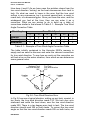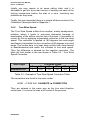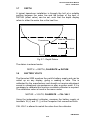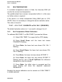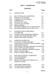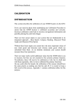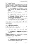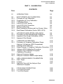
1
Hercules 2000 User Manual
Part 3 - Calibration
PART 3 - CALIBRATION
CONTENTS
Para
Page
3.1
INTRODUCTION
3-3
3.2
3.2.1
3.2.2
3.2.3
3.2.4
3.2.5
3.2.6
3.2.7
3.2.8
BOAT SPEED/LOG CALIBRATION
Principle of Log Calibration
Preparation for Log Calibration
Calibration Runs
Log AUTO CAL Facility
Log AUTO CAL Procedure
Manual Calibration
Boat Calibration Referenced to a Known Value
Boat Speed Calibration (Knots, MPH, KPH)
3-4
3-4
3-4
3-5
3-5
3-6
3-7
3-7
3-8
3.3
3.3.1
3.3.2
3.3.3
APPARENT WIND SPEED AND ANGLE
Principles of Wind Speed/Angle Calibration
Apparent Wind Angle Calibration (AWA)
Apparent Wind Speed
3-9
3-9
3-11
3-12
3.4
3.4.1
COMPASS CALIBRATION
Principles of Compass Calibration (Super
Halcyon 3 & Halcyon 2000 Compasses)
Heading Node Selection
Super Halcyon 3 Compass Calibration Procedure
Halcyon 2000 Calibration Procedure
Halcyon Gyro Stabilised Compass
Calibration Procedure
Halcyon Processor Setup
Halcyon Processor NMEA output setup
3-13
3-13
3.4.2
3.4.3
3.4.4
3.4.5
3.4.6
3.4.7
3-14
3-15
3-16
3-17
3-18
3-19
3.5
3.5.1
3.5.2
3.5.3
HEEL ANGLE/LEEWAY CALIBRATION
Heel Angle
Leeway
Heel and Trim with the Halcyon Gyro
Stabilised Compass
3-19
3-19
3-20
3-21
3.6
3.6.1
3.6.2
TRUE WIND CORRECTION
True Wind Direction
True Wind Speed
3-22
3-22
3-26
HB-0845-04
3-1
Hercules 2000 User Manual
Part 3 - Calibration
CONTENTS (Contd.)
Para
Page
3.7
DEPTH
3-27
3.8
BATTERY VOLTS
3-27
3.9
3.9.1
SEA TEMPERATURE
Sea Temperature Offset Calibration
3-28
3-28
3.10
TIMER
3-29
ILLUSTRATIONS
Fig No
3.1
3.2
3.3
3.4
3.5
3.6
3.7
Page
Calibration Runs
Masthead Unit Alignment
Leeway Angle Measurement
True Wind Direction
Upwash
True Wind Direction Error
Depth Datum
3-5
3-12
3-20
3-22
3-23
3-24
3-27
TABLES
Table No
Page
3.1
3.2
3-24
3-26
True Wind Angle Correction
True Wind Speed Correction
HB-0845-04
3-2
Hercules 2000 User Manual
Part 3 - Calibration
3.4
COMPASS CALIBRATION
3.4.1
Principles of Compass Calibration (Super Halcyon 3,
Halcyon 2000 & Halcyon Gyro Stabilised Compasses)
B&G's Autoswing Compasses contain software that allows them to
record the magnetic fields in the yacht that are causing the
deviation errors. It calculates the corrections every time the boat
completes a 540° turn - Super Halcyon 3 or 360° turn - Halcyon
2000, provided the following conditions are met:
(a) The 540° turn - Super Halcyon 3 or 360° turn Halcyon 2000 & Halcyon Gyro Stabilised Compass is
completed in the same direction.
(b) The rate of change of heading does not exceed 3°/s;
i.e. the turn should take about 3 minutes to complete.
(c) The rate of change of heading must not fall below 0.2
of a degree per second during the 540° turn - Super
Halcyon 3, i.e. the 540° turn must not take longer than 45
minutes.
(d) The rate of change in heading is constant.
(e) Automatic calibration has been utilised by connecting
the brown wire from the compass at the junction box.
(Super Halcyon 3 only)
(f) The compass is installed in a location free from
magnetic interference such as iron keels, engines,
loudspeakers etc. Consideration should also be given to
electrical cables which may carry excessive currents (e.g.
navigation lights).
(g) The compass is installed in a location as close to the
centre line of the boat as possible. Avoid areas such as
the fore peak and the sides of the hull where the effects
of pitch and roll are at their greatest.
(h) On steel hulled vessels, the compass will need to be
installed above decks away from the effects of the hull.
Ideally, the compass should be installed 4-5m (12-16ft)
above deck level.
HB-0845-04
3-13
Hercules 2000 User Manual
Part 3 - Calibration
3.4.2
Heading Node Selection
The Hercules 2000 System can accept heading data from a
variety of different sources. These different sources are known as
Nodes and allow the system to identify which heading devices are
connected to the system. The list below shows the various
sources of heading available with its respective address node:
Device
Node
Super Halcyon 3 Compass
5
Halcyon Gyro Stabilised Compass
15
Halcyon 2000 Compass
16
Type PLC Pilot
17
Type ACP Pilot
18
NMEA Heading (NMEA FFD)
96
Enter the required heading node by following the procedure below:
(a) Press the Scroll Up key until NAVIGATE is shown in
the text, flashing.
(b) Press Enter.
(c) Press the Scroll Up key again until the display shows
COURSE °M flashing.
(d) Press Enter. COURSE °M will now stop flashing.
(e) Press Scroll
CALBRATE.
Down
until
the
display
shows
(f) Press Enter 3 times. The display now shows HDG NO
and will display a value which flashes.
(g) Use the Scroll Up and Scroll Down keys to change
the value to the required setting.
(h) Press Enter.
(I) Switch the system off, and then back on again to
complete the calibration process.
Notes
(1) Hydra Pilots, Hercules Pilots, HS Pilots and Halcyon FFDs will
also require the Heading Node to be set to your desired choice.
Refer to the relevant user manual for further information.
HB-0845-04
3-14
Hercules 2000 User Manual
Part 3 - Calibration
(2) 20/20 displays will require Heading to be re-selected. Simply
re-select this function and refer to section 5.4.5 for more
information.
3.4.3
Super Halcyon 3 Compass Calibration Procedure
(1) Check for any magnetic devices placed near the
compass, especially ones that are out of their normal
places.
(2) On a calm day select a stretch of open water with
little traffic, (so you will not have to take avoiding action
that would ruin the calibration). The flatter the water and
the less the wind the easier it will be to meet the
conditions for the calibration.
(3) Check for any large steel structures nearby that may
cause additional erratic deviations.
(4) At a speed of about three knots slowly motor the boat
through a full one and a half turns (540°), taking six to
fifteen minutes to complete the one and a half turns. At
this rate the heading should be changing at no faster than
one degree every second. Having a watch beside the
compass display should considerably assist the
helmsman in monitoring the rate of turn. The rate of turn
is indicated on the Halcyon Display.
(5) When the compass has completed its calibration, the
displayed heading will rotate in the opposite direction for
360° and settle on the correct bearing to indicate the
calibration is complete. You should continue to turn until
you see this.
Note
If the displayed heading does not reverse, the calibration was
discarded because the conditions were not met. You must start
again, or try another day when wind and wave conditions are
calmer.
(6) Eliminate any constant error in heading. These are
normally checked for by using shore-based transits, once
the error is known it can be eliminated by entering the
value into the Hercules under:
NAVIGATE → HEADING, CALBRATE → CAL VAL1
For example, the compass was reading 320 degrees and it should
read 316, then the value to enter would be -4.
HB-0845-04
3-15
Hercules 2000 User Manual
Part 3 - Calibration
3.4.4
Halcyon 2000 Calibration Procedure
(1) Check for any magnetic devices placed near the
compass, especially ones that are out of their normal
places.
(2) On a calm day select a stretch of open water with
little traffic (so you will not have to take avoiding action
which would ruin the calibration). The flatter the water and
the less the wind the easier it will be to meet the
conditions for calibration.
(3) Check for any large steel structures nearby, that may
cause additional, erratic deviations.
(4) Scroll to the NAVIGATE menu and select COMP CAL
on the top half of the display. The display shows OFF.
(5) Press Scroll Down until the lower text shows
CALBRATE flashing.
(6) Press the Enter key twice to display START and a
default setting of ‘0’.
(7) Press the Enter key once and the ‘0’ starts to flash.
Use the Scroll Up key to change the value to ‘1’.
(8) Press the Enter key. The display now shows 000°.
(9) At a speed not exceeding five knots, turn the boat
through 360° at a rate not greater than 2-3° per second.
The display will show the amount of turn completed so
far. Continue to turn the boat until the display shows
PASS or FAIL.
Notes
1. The compass calibration swing may be aborted at any time. To
do this, press the Enter key once. Next, using the Scroll Down
key change the value from ‘1’ to ‘0’, and then press Enter to
store. The display will now show OFF.
2. The first time the system is switched on, or after a system reset,
the Heading will alternate with CAL. This is to indicate to the
user that the compass must be calibrated. This will disappear
after the compass has been calibrated.
HB-0845-04
3-16
Hercules 2000 User Manual
Part 3 - Calibration
(10) Eliminate any constant error in heading. These are
normally checked for by using shore-based transits, once
the error is known it can be eliminated by entering the
value into the Hercules under:
NAVIGATE → HEADING, CALBRATE → CAL VAL1
For example, the compass was reading 320 degrees and it should
read 316, then the value to enter would be -4.
3.4.5
Halcyon Gyro Stabilised Compass Calibration
Procedure
(1) Check for any magnetic devices placed near the
compass, especially ones that are out of their normal
places.
(2) On a calm day select a stretch of open water with
little traffic (so you will not have to take avoiding action
which would ruin the calibration). The flatter the water and
the less the wind the easier it will be to meet the
conditions for calibration.
(3) Check for any large steel structures nearby, that may
cause additional, erratic deviations.
(4) Scroll to the MISC menu and select HALCYON on the
top display. GYRO will be displayed in the top data line if
a Halcyon Gyro Stabilised Compass is connected.
(4) Press scroll down until the lower text shows
‘CALIBRATE’ press the ENTER key
(6) Press scroll down until the lower text shows
CALIBRATE, press the ENTER key, and scroll down to
CAL VAL 1, press enter and START will be displayed with
‘0’ as a default value.
(7) Press enter and the ‘0’ starts to flash. Use the scroll
up key to change the value to ‘1’.
(8) Press the Enter key. The display now shows 000°.
(9) At a speed not exceeding five knots, turn the boat
through 360° at a rate not greater than 2-3° per second.
The display will show the amount of turn completed so
far. Continue to turn the boat until the display shows
PASS or FAIL. If you receive FAIL you must re-calibrate
your compass.
HB-0845-04
3-17
Hercules 2000 User Manual
Part 3 - Calibration
Notes
1.
2.
The compass calibration swing can be aborted at any
time. To do this press the enter key once. Next press
the scroll down key and change the value from ‘1’ to
‘0’.
You can re-calibrate at any time by following the above
procedures.
(1) If you have any constant error in your heading, you
can correct for this.
Enter the value to offset your heading e.g. if your
heading displays 100° and it should read 97°, then the
value to enter would be –3.
The M indicates Magnetic reference headings and a T will indicate
True referenced headings.
3.4.6
Halcyon Gyro Processor Setup
Data under the MISC > HALCYON heading describes the setup of
the Halcyon Gyro Processor, and are as follows:
OFF
GYRO
SYS
PASS
FAIL
xxxº
No heading source from either a Halcyon Gyro
Stabilised Compass or a B&G system compass
Receiving data from Halcyon Gyro Stabilised
Compass or NMEA input to Halcyon Gyro
Processor
Receiving data from a B&G system compass or
NMEA input to NMEA FFD or performance
processor
Calibration swing is complete
Calibration swing failed and the compass needs
to be re-calibrated.
Number of degrees turned during calibration
swing
HB-0845-04
3-18
Hercules 2000 User Manual
Part 3 - Calibration
3.4.7
Halcyon Gyro Processor NMEA output setup
NMEA sentence output settings determine what sentences are
output with respect to which heading source is available.
MISC>HALCYON, CALIBRATE>CAL VAL 2 (NMEA MDE)
0=HDT from Halcyon Gyro Stabilised Compass or NMEA input to
Halcyon Gyro Processor
1=HDM from Halcyon Gyro Stabilised Compass or NMEA input to
Halcyon Gyro Processor
2=HDG from Halcyon Gyro Stabilised Compass or NMEA input to
Halcyon Gyro Processor
3=HDM/HDT from a B&G system [compass or NMEA input], or
NMEA input to Halcyon Gyro Processor
4=HDG from a B&G system [compass or NMEA input], or NMEA
input to Halcyon Gyro Processor
NOTE:
Mode 0 is the default value
Mode 3 will output the correct sentence depending on
configuration.
Navigate > Heading, CALIBRATE>CAL VAL 2.
0 = Magnetic
1 = Auto (will set to True if Mag var is available, otherwise
will stay in Magnetic)
If Mode 4 is selected and magnetic variation is not available then
the magnetic heading will be output.
3.5
HEEL ANGLE/LEEWAY CALIBRATION
Calibration of Heel Angle and Leeway is only necessary if a Heel
Angle Sensor or Clinometer is fitted to the yacht. The fitting of this
sensor is highly recommended because it allows the calculation of
Leeway and hence course corrected for Leeway which is used in
the calculation of Dead Reckoning.
3.5.1
Heel Angle
The Heel Angle sensor, or clinometer, should be mounted to read
zero when the boat is upright. However any error can be removed
by means of the heel angle calibration.
HB-0845-04
3-19
Hercules 2000 User Manual
Part 3 - Calibration
On a calm day with the boat lying at slack warps in the dock, head
to wind, all the gear stowed in its normal place, and anyone
onboard standing on the centreline the heel angle should be
recorded, under these conditions it should be zero, any error can
be taken out by the heel angle calibration, by adding or subtracting
the error from the existing calibration.
Heel angle calibration is to be found in the system menu under:
PERFORM → HEEL, CALBRATE → CAL VAL1
3.5.2
Leeway
Calibrating leeway is a notoriously difficult thing to do; it may be
easier, and as accurate, to consult the yachts designer who may
have a theoretical value for leeway coefficient, as it is to try to
measure it. Should that not be possible then we can calculate the
Leeway coefficient from the following formula:
L = KxH
Bs x Bs
where, Bs = Boat Speed
K = Leeway Coefficient
H = Heel Angle
L = Leeway Angle
K then is the constant that needs to be entered, and to establish a
value for leeway coefficient we need to measure the leeway angle
at a particular heel angle and boat speed shown in Fig 3.3 below.
Back Bearing
80˚
g-1
adin
Leeway Angle
He
se
Cour
ding
Hea
ers
Mark
Fig 3.3 Leeway Angle Measurement
The idea is to sail on a steady course and drop markers over the
stern at regular intervals, the angle between them and the
HB-0845-04
3-20
Hercules 2000 User Manual
Part 3 - Calibration
centreline of the yacht is measured with a hand bearing compass,
and hence leeway angle is measured. Whilst this is happening the
boat speed and heel angle should be noted at intervals and an
average calculated. These values can then be used to calculate
the leeway coefficient from the following expression.
K = L x Bs x Bs
H
Obviously the flatter the water and the steadier the breeze the
more likely this is to be successful, but even in perfect conditions it
is difficult, to say the least. Once you have the leeway coefficient
'K' then it is entered into the system under:
NAVIGATE → LEEWAY, CALBRATE → CAL VAL1
3.5.3
Heel and Trim angle with the Halcyon Gyro Stabilised
Compass.
The heel and trim information from the Halcyon Gyro Stabilised
Compass is displayed in the PERFORM menu.
The H symbol will be placed on left indicating heel to port and on
the right for heel to starboard. The display will always be shown to
1 decimal point
The U symbol on the left indicates that the bow is up, while a d
will be shown indicating bow down. The display will always be
shown to 1 decimal point
Both heel and trim have an offset calibration to allow for any
constant errors, adding or subtracting from CAL VAL 1 will correct
this.
PERFORM → HEEL, CALIBRATE → CAL VAL 1
PERFORM → TRIM, CALIBRATE → CAL VAL 1
If you have heel and trim sensors connected to your system as
well as a Halcyon Gyro Stabilised Compass then the Heel and
Trim from the Compass will be used by default. If you wish to use
your external sensors then set CAL VAL 2 to ‘0’.
PERFORM → HEEL, CALIBRATE → CAL VAL 2
PERFORM → TRIM, CALIBRATE → CAL VAL 2
HB-0845-04
3-21
Hercules 2000 User Manual
Part 3 - Calibration
3.6
TRUE WIND CORRECTION
It is finally time to go sailing and begin the calibration of the true
wind direction and speed.
3.6.1
True Wind Direction
The need for further calibration of true wind direction will become
clear as soon as you go sailing. The true wind might vary in
direction from tack to tack, independently of any wind shifts. This
phenomenon has come to be known as the true wind 'tacking'.
The reason it happens is because the true wind angle that the
instruments are calculating is wrong. We can see the direct
connection between true wind angle and direction in Fig 3.4 below.
True Wind
Direction
=280˚
Heading
=240˚
TWA
=40˚
Fig 3.4 - True Wind Direction
The reason for this is a variety of errors that enter into the
calculation of true wind angle from apparent wind angle, one of the
largest of which is Upwash, an aerodynamic effect which is shown
in Fig 3.5 - Upwash.
HB-0845-04
3-22
Hercules 2000 User Manual
Part 3 - Calibration
MHU
Fig 3.5 - Upwash
In Fig 3.5 the apparent wind that the instruments measure is
actually deflected from the 'real' apparent wind angle which we
need to calculate the true wind. Add to this the various twisting
effects of the mast and the Masthead Unit, and we get some idea
of the problems involved. The hardest part is that it is easy to see
the true wind direction 'tack' as little as 2-3 degrees, which would
mean the correction factors being as accurate as 0.5 degree, or
about 1%. This is why calibration of the true wind has been so
difficult historically, because the approach has always been to
research these effects and write formulas that automatically
correct them for the user. The Hercules 2000 takes a whole new
approach because our research has shown that the EFFECTS
ARE NOT CONSTANT. For any particular windspeed the
correction needed for all these errors has to be different from day
to day, not least because of the problems of wind gradient we
discussed earlier.
So what is required is not yet another attempt to automatically
correct these errors, but a simple, easy-to-use system whereby
you can correct them yourself on a day-to-day basis. And this is
what the Hercules 2000 provides.
HB-0845-04
3-23
Hercules 2000 User Manual
Part 3 - Calibration
How does it work? As we have seen the problem stems from the
true wind direction 'tacking' as the boat manoeuvres from tack to
tack. So what we need to know is the error that the true wind
suffers in any manoeuvre, be it a normal upwind tack, a reach to
reach tack, or a downwind gybe. Once you know the error, and the
windspeed you had at the time, then we can enter it as a
correction. What we are aiming to do is build up a table of
corrections similar to that shown in Table 3.1 - Example True Wind
Angle Correction Table.
Wind Angle
5
2
3
0
Upwind
Reaching
Downwind
10
5
5
0
True Wind Speed
15
20
3
2
6
5
0
0
25
1
4
0
30
1
3
0
Table 3.1 - Example of True Wind Angle Correction Table
The table initially contained in the Hercules 2000’s memory is
empty and we need to discover and enter the relevant corrections
for true wind direction. To see how we work out the correction we
will look at an on the water situation, from which we can determine
some general rules.
Starboard Tack
true wind direction
200˚
Heading
=160˚
10˚
40˚
Port Tack
true wind direction
210˚
40˚
Heading
=250˚
Fig 3.6 -True Wind Direction Error
In Fig 3.6 we see a typical situation, sailing on port tack, upwind, in
ten knots, the true wind direction reads 210. We tack over onto
starboard and settle the boat down, now the true wind direction
reads 200. There is a ten degree error tack to tack. The true wind
direction should read 205 on both tacks. To correct the true wind
angle so that the true wind direction reads 205 on both tacks, we
HB-0845-04
3-24
Hercules 2000 User Manual
Part 3 - Calibration
need to add 5 degrees to the true wind angle. So for a general rule
we can say:
If the wind direction is higher on port tack than starboard, we
need to ADD HALF the DIFFERENCE between the readings on
the two tacks, to the true wind angle.
And the converse will apply:
If the wind direction is lower on port tack than on starboard,
we need to SUBTRACT HALF the DIFFERENCE between the
readings on the two tacks, to the true wind angle.
This works whether you are tacking upwind, gybing downwind or
tacking reach to reach.
All we need to do now is tell the Hercules 2000 the correction
value at each of the points in the table. The true wind correction
facility, is found in the menu under:
WIND → TRUE W/A, CALBRATE → CORRECTION
This then allows you to scroll through all the correction values in
the table (using Scroll Up or Scroll Down) until you find the one
where you wish to enter a correction, in our example above we
would be looking for "upwind, 10 knots". Once you have scrolled
through to this, a press of the Enter Key will allow you to enter the
required number of degrees correction (i.e. +5) using the Scroll
Up and Scroll Down Keys to increase/decrease the value
accordingly. A final press of the Enter Key stores this to the
Hercules 2000.
In the early stages of calibration when the table is nearly empty, it
is important to enter the same value of correction to the
windspeeds either side of the one you are using. This is to avoid
the true wind direction jumping in value when the wind speed
drops or increases outside the range you are correcting.
As your table gets closer to being finished you will be able to make
individual changes, because the other corrections will be accurate
enough to avoid any strange "step" changes as the true wind
speed varies. For this reason it is very important to enter all these
corrections into a Calibration Chart (see Appendix 1). This way
you will notice any big gaps in the correction table where you have
entered no values at all.
HB-0845-04
3-25
Hercules 2000 User Manual
Part 3 - Calibration
Initially you may require to do some sailing trials, and it is
advisable to get into a pre-start routine of carrying out each of the
tacking manoeuvres before the start of a race, correcting any
problems as they arise.
Finally, the most important thing is to record all these entries in the
Calibration Charts provided in Appendix 1.
3.6.2
True Wind Speed
The True Wind Speed suffers from another, mainly aerodynamic,
problem, where it tends to over-read downwind because of
acceleration of the airflow over the top of the mast. It is possible to
correct for this by applying a downwind correction to the true wind
speed. This correction is applied at 180 degrees true wind angle
and linearly interpolated to zero correction at 90 degrees true wind
angle. The routine here is to bear away quickly from close-hauled
to dead-downwind and watch the increase in true wind speed.
Then the difference is entered as the negative correction. The
table will look similar to the one shown in Table 3.2 - True Wind
Speed Correction.
Wind Angle
Downwind 180
5
0
True Wind Speed
10
15
20
25
-0.5
-1.0
-1.5
-2.0
30
-2.5
Table 3.2 - Example of True Wind Speed Correction Table
The corrections are found in the menu under:
WIND → TRUE W/S, CALBRATE → CORRECTION
They are entered in the same way as the true wind direction
corrections. It is crucial to keep a full record of the process.
HB-0845-04
3-26
Hercules 2000 User Manual
Part 3 - Calibration
3.7
DEPTH
A typical transducer installation is through the hull at a suitable
position between the water line and the bottom of the keel. A
DATUM (offset value) can be set, such that the depth display
refers to either the water line or the keel line.
Transducer
Add for Waterline
Subtract for Keel
Fig 3.7 - Depth Datum
The datum is entered under:
DEPTH → DEPTH, CALBRATE → DATUM
3.8
BATTERY VOLTS
The Hercules 2000 monitors the yacht's battery supply and can be
called up on any display, giving a reading in volts. This is
calibrated by the manufacturer and should not require adjustment
except in exceptional circumstances or after a system reset. If it is
necessary to calibrate this function a suitable voltmeter is required.
The calibration value is found in the menu under:
MOTOR → VOLTS, CALBRATE → CAL VAL1
Using the independent voltmeter, measure the battery supply at
terminals 18 (+) and 17 (-) at the Computer Unit connection block.
CAL VAL1 is altered to match the value from the voltmeter.
HB-0845-04
3-27
Hercules 2000 User Manual
Part 3 - Calibration
3.9
SEA TEMPERATURE
If a suitable temperature sensor is fitted, the Hercules 2000 will
monitor the current sea temperature.
The paddle-wheel has a sensor incorporated within it, in this case
no further action is required.
If the sensor is a totally independent fitting (B&G part no. 22300-027) then it is necessary to change the sensor selection value.
This value is found in:
TEMP → SEA TEMP, CALBRATE → CAL VAL1 (SENSORS)
The default selection value is a 1, we need to change it to a 2.
3.9.1
Sea Temperature Offset Calibration
To calibrate SEA TEMP C or SEA TEMP F proceed as follows:
(1) Select SEA TEMP C on upper half on FFD display
(2) Press Scroll Down until the lower text shows
CALBRATE flashing
(3) Press Enter, the lower text now shows CAL VAL 1
flashing
(4) Press Scroll Down, the lower text now shows CAL
VAL 2 flashing
(5) Press Enter, the lower text now shows OFFSET C
(6) Press Enter, the lower text now shows OFFSET C
flashing and by use of Scroll Up/Down the reference
temperature may be entered.
(7) Press Enter, the offset value is accepted and the
upper display will show the adjusted measured
temperature.
Similarly the above calibration can be carried out if SEA TEMP F
is initially selected.
HB-0845-04
3-28
Hercules 2000 User Manual
Part 3 - Calibration
The offset value is automatically converted so that both degrees C
and F are adjusted correctly.
3.10
TIMER
The Timer uses a stable quartz crystal to provide an accurate time
base when calibrated. The calibration is set when the unit is
manufactured and should not normally require further adjustment.
If adjustment is necessary the calibration can be found as follows:
TIME → TIMER, CALBRATE → CAL VAL1
The Calibration value is the number of seconds correction required
a day. If the timer is gaining then the number of seconds it is
gaining a day should be subtracted from the current calibration
value. If the timer is losing the number of seconds lost a day
should be added to the current calibration value.
HB-0845-04
3-29