1
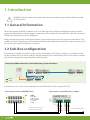
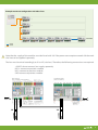
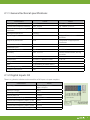
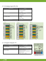
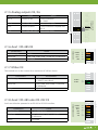
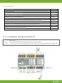
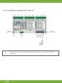
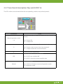
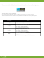
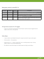
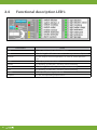
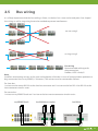
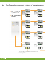
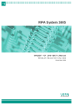
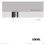
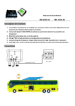
User Manual myGEKKO RIO modules V 0.21 ® Latest Update: July 2012 All software-related descriptions refer to the V1279 software. An update is recommended for older versions of the system. Small deviations of the descriptions are possible and due to changes in the software. All brands and logos are registered trademarks and are the property of the respective holders of the rights Copyright All rights reserved. No parts of this document may be reproduced or transmitted in any form by any means, electronic or mechanical, without the prior written authorization of its legal owner. If this publication is made available on Ekon GmbH media, Ekon gives its consent to downloading and printing copies of the content provided in this file only for private use and not for redistribution. No part of this publication may be modified, altered or used for commercial purposes. Ekon GmbH is not liable for the damages which arise from the use of an illegal modified or altered publication. All products correspond to the directly applicable EU regulations and guidelines. 2 Table of Contents 1. Introduction 1.1 General Information . . . . . . . . . . . . . . . . . . . . . . . . . . . . . . . . . . . . . . . . . . . . . . . . . . . . . . . . . . . . . . . . . . . . . . . . 4 1.2 Sub-Bus configuration . . . . . . . . . . . . . . . . . . . . . . . . . . . . . . . . . . . . . . . . . . . . . . . . . . . . . . . . . . . . . . . . . . . . . . 4 2. Technical specifications 2.1 Rio 29 2.1.1 General technical specifications . . . . . . . . . . . . . . . . . . . . . . . . . . . . . . . . . . . . . . . . . . . . . . . . . . . . . . . . . . . 6 2.1.2 Digital inputs X4 . . . . . . . . . . . . . . . . . . . . . . . . . . . . . . . . . . . . . . . . . . . . . . . . . . . . . . . . . . . . . . . . . . . . . . . . . . 7 2.1.3 Analog inputs X5, X6 . . . . . . . . . . . . . . . . . . . . . . . . . . . . . . . . . . . . . . . . . . . . . . . . . . . . . . . . . . . . . . . . . . . . . . 8 2.1.4 Digital outputs X7 . . . . . . . . . . . . . . . . . . . . . . . . . . . . . . . . . . . . . . . . . . . . . . . . . . . . . . . . . . . . . . . . . . . . . . . . 8 2.1.5 Analog outputs X5, X6 . . . . . . . . . . . . . . . . . . . . . . . . . . . . . . . . . . . . . . . . . . . . . . . . . . . . . . . . . . . . . . . . . . . . . 9 2.1.6 Aux1 / RS-485 X3 . . . . . . . . . . . . . . . . . . . . . . . . . . . . . . . . . . . . . . . . . . . . . . . . . . . . . . . . . . . . . . . . . . . . . . . . . 9 2.1.7 MBus X3 . . . . . . . . . . . . . . . . . . . . . . . . . . . . . . . . . . . . . . . . . . . . . . . . . . . . . . . . . . . . . . . . . . . . . . . . . . . . . . . . . . 9 2.1.8 Aux2 / RS-485 or RS-232 X3 . . . . . . . . . . . . . . . . . . . . . . . . . . . . . . . . . . . . . . . . . . . . . . . . . . . . . . . . . . . . . . . 9 2.1.9 Screw terminals. . . . . . . . . . . . . . . . . . . . . . . . . . . . . . . . . . . . . . . . . . . . . . . . . . . . . . . . . . . . . . . . . . . . . . . . . . 10 2.1.10 Spring clamp terminals . . . . . . . . . . . . . . . . . . . . . . . . . . . . . . . . . . . . . . . . . . . . . . . . . . . . . . . . . . . . . . . . . 10 2.1.11 Installation specifications RIO 29 . . . . . . . . . . . . . . . . . . . . . . . . . . . . . . . . . . . . . . . . . . . . . . . . . . . . . . . . 11 2.1.12 Functional description Dip switch RIO 29. . . . . . . . . . . . . . . . . . . . . . . . . . . . . . . . . . . . . . . . . . . . . . . . . 12 2.2. Aux-8 2.2.1 General technical specifications . . . . . . . . . . . . . . . . . . . . . . . . . . . . . . . . . . . . . . . . . . . . . . . . . . . . . . . . . 14 2.2.2 Digital PWM inputs X100 . . . . . . . . . . . . . . . . . . . . . . . . . . . . . . . . . . . . . . . . . . . . . . . . . . . . . . . . . . . . . . . . 15 2.2.3 Analog outputs X101 . . . . . . . . . . . . . . . . . . . . . . . . . . . . . . . . . . . . . . . . . . . . . . . . . . . . . . . . . . . . . . . . . . . . . 15 2.2.4 Connection example. . . . . . . . . . . . . . . . . . . . . . . . . . . . . . . . . . . . . . . . . . . . . . . . . . . . . . . . . . . . . . . . . . . . . . 16 2.2.5 Installation specifications. . . . . . . . . . . . . . . . . . . . . . . . . . . . . . . . . . . . . . . . . . . . . . . . . . . . . . . . . . . . . . . . . 16 2.2.6 Spring clamp terminals. . . . . . . . . . . . . . . . . . . . . . . . . . . . . . . . . . . . . . . . . . . . . . . . . . . . . . . . . . . . . . . . . . . . 17 2.3. Rio 16 2.3.1 General technical specifications . . . . . . . . . . . . . . . . . . . . . . . . . . . . . . . . . . . . . . . . . . . . . . . . . . . . . . . . . 18 2.3.2 Digital inputs X4 . . . . . . . . . . . . . . . . . . . . . . . . . . . . . . . . . . . . . . . . . . . . . . . . . . . . . . . . . . . . . . . . . . . . . . . . . 19 2.3.3 Digital outputs X5, X6, X7 . . . . . . . . . . . . . . . . . . . . . . . . . . . . . . . . . . . . . . . . . . . . . . . . . . . . . . . . . . . . . . . . . 20 2.3.4 Screw terminals. . . . . . . . . . . . . . . . . . . . . . . . . . . . . . . . . . . . . . . . . . . . . . . . . . . . . . . . . . . . . . . . . . . . . . . . . . 20 2.3.5 Spring clamp terminals. . . . . . . . . . . . . . . . . . . . . . . . . . . . . . . . . . . . . . . . . . . . . . . . . . . . . . . . . . . . . . . . . . . 21 2.3.6 Installation specifications RIO 16 . . . . . . . . . . . . . . . . . . . . . . . . . . . . . . . . . . . . . . . . . . . . . . . . . . . . . . . . . 22 2.3.7 Functional description Dip switch RIO 16. . . . . . . . . . . . . . . . . . . . . . . . . . . . . . . . . . . . . . . . . . . . . . . . . 23 2.4 Functional description LEDs . . . . . . . . . . . . . . . . . . . . . . . . . . . . . . . . . . . . . . . . . . . . . . 26 2.5 Buswiring . . . . . . . . . . . . . . . . . . . . . . . . . . . . . . . . . . . . . . . . . . . . . . . . . . . . . . . . . . . . . . . 27 2.6 Configurations example . . . . . . . . . . . . . . . . . . . . . . . . . . . . . . . . . . . . . . . . . . . . . . . . . 28 2.7 Schematic example . . . . . . . . . . . . . . . . . . . . . . . . . . . . . . . . . . . . . . . . . . . . . . . . . . . . . 30 3. Installation manual. . . . . . . . . . . . . . . . . . . . . . . . . . . . . . . . . . . . . . . . . . . . . . . . . . . . . . . . . 32 4. Software activation at myGEKKO. . . . . . . . . . . . . . . . . . . . . . . . . . . . . . . . . . . . . . . . . . . . 33 3 3 1. Introduction ! WARNING: Read all safety information and instructions before using the RIO modules in order to avoid injuries. 1.1 General Information The basic function of the RIO-modules consists of data acquisition (digital and analogue inputs) and the triggering of digital and analogue outputs respectively. RIO-modules are controlled via a RS-485 connection. The devices themselves have no intelligence. Solely, the operating status of the digital outputs can be determined in case of communication failure. The modules are built-in appliances and may be installed only by qualified personnel. The necessary covers must be in place (see section installation instruction). 1.2 Sub-Bus configuration The maximum number of modules which can be connected to a RIO-29 bus coupler is 16 modules including bus coupler. Rio 16 or Rio 29 modules may be attached also in combination at will. The sub-bus modules may also be mounted on several distributors distinctively. Example myGEKKO with one bus line divided among several distributors Rio-16 RS485 RS485 Rio-29 Rio-16 Rio-29 Rio-16 Rio-16 Rio-29 A maximum of 4 bus lines can be operated on a myGEKKO Touch (4 bus couplers RIO29). Connections at the myGEKKO Touch PIN 2 3 4 7 8 SIGNAL RS485_GND RS485_TX (RxTx+) RS485_#TX (RxTx-) V+ (10-32V) V_GND recommended cable type Profibus L2FIP 1x2x0,65 4 Connections at the RIO29 bus coupler to the Sub-Busmodules Example maximum configuration with 4 Bus-lines ... Rio-29 ... Rio-29 ... Rio-29 16 modules Rio-29 Rio-29 Rio-29 Rio-29 Rio-29 Rio-16 Rio-16 RS485 RS485 Note that the supply of the modules must be fused with 3A. If the power consumption exceeds 3A the modules have to be supplied separately. The bus must be wired accordingly to X1 or X2 (sub-bus). Therefore, the following connections are required: +24VDC do not connect, but supply separately RxTx+ connect to previous module RxTx- connect to previous module GND connect to previous module Bus coupler (1st module of the busline) Sub-Busmodule (more modules) max. 3 A max. 3 A 3A +24VDC GND 3A +24VDC GND ! 5 2. Technical specifications 2.1 RIO 29 6 2.1.1 General technical specifications Parameters Supply voltage Current consumption (internal) Temperature range during operation Storage temperature Operating time Value 24VDC max. 250mA - 20-50°C - 40-85°C 100% ED Degree of protection IP20 Contamination level Protection class Principle of operation Humidity 2 II Type 1 max. 75% r.H. Software class Dimensions Weight EMV Rated surge voltage Output PV at 24 VDC Class A 162mm x 110mm x 62mm 280g CE according to 2004/108/EG 0,5kV 3W Notes -25% / +30% Typ. 100mA @ 24VDC designed for continuous operation established via appropriate installation EN60730-1 without condensation, during operation LxWxH 2.1.2 Digital Inputs X4 There is a galvanic isolation to the modules of all inputs via opto-couplers. Parameters Input type Isolation voltage Switch point On Switch point Off Maximum input voltage Current consumption / Input Current consumption / Input Current consumption / Input Current consumption / Input @ 10V @ 18V @ 24V @ 28V Value Optically separated / opto-couplers 400V >9VDC <5VDC 24VDC +30% 2mA 3.8mA 5.5mA 6.2mA 7 2.1.3 Analog inputs X5, X6 Parameters UI-x input range II-x input range TI-x input range TI-x temperature range 0-20 mA Value 0-10V voltage input 1mV (16 Bit ADC) 0 – 10’000 0-20mA current input 10uA (12 Bit ADC) 0 – 2’000 uA PT1000 0,1 Grad -500 – 2’500 -50 – 250°C 0-10 VDC PT 1.000 2.1.4 Digital Outputs X7 Parameters Type of output Output current Power supply 8 Value/Notes PWM outputs / galv. non-insulated 0,5A / Short-circuit-proof Separate feeding (Supply must be fused externally with 5A) 24VDC -25% / +30% www.my-gekko.com 21 22 23 24 25 www.my-gekko.com AUX1: RS485 AUX2: RS485/RS232 12 13 14 15 16 17 18 19 9 20 10 11 12 21 13 22 14 23 15 24 16 25 17 26 18 27 19 28 9 20 29 10 30 11 21 12 13 22 14 23 15 24 16 25 17 26 18 27 19 28 20 29 30 0,25 ..0,5 0,14 ..0,5 my-GEKKO RIO-29 my-GEKKO RIO-29 my-GEKKO RIO-29 AUX1: RS485 U: Voltage 0..10V DC I: Current 0..20mA AO-2 AUX2: RS485/RS232 U: Voltage 0..10V DC I: Current 0..20mA AI-8 Parity AI-7 1200, 2400, 4800, 9600, 19’200 and 38’400 baud adjustable +24VDC RxTx+ RxTxGND RxD TxD RxTxGND AI-6 Baud rate +24VDC RxTx+ UI-1 II-1 TI-1 Gnd UI-2 II-2 TI-2 Gnd UI-3 II-3 TI-3 Gnd UI-4 II-4 TI-4 Gnd 9 UO-110 IO-1 GND 11 AI-5 Value RS-485 oder RS-232 GND 79 80 +24VDC 81 RxTx+ 82 RxTx83 84GND 85RxD 86TxD 87 88 M-Bus 89 + M-Bus 90 AI-4 AO-1 Parameters Interface type 51 52 53 54 55 56 57 58 59 60 61 62 63 64 65 +24VDC 66 RxTx+ 67 68 RxTx69 1 1 Aux2 can either be operated as an RS-485 or RS-232 interface. Digital Outputs DO-1 .. DO-8 2.1.8 Aux2 / RS-485 oder RS-232 X3 Analog-IO AI-5 .. AI-8, AO-2 www.my-gekko.com Max. load 500 Ohm 9 10 11 12 13 14 15 2.1.6 Aux1 / RS-485 X3 16 17 Parameters Value 18 19 Interface type RS-485 20 Baud rate 1200, 2400, 4800, 9600, 19’200 and 38’400 baud Parity adjustable 21 22 23 24 2.1.7 M-Bus X3 25 26 The module acts as bus master for a maximum of 3 M-bus slaves. 27 28 Parameters Value/Notes 29 Interface type 30 M-Bus / +/-30VDC max. 60mA Baud rate 1200, 2400, 4800, 9600, 19’200 and 38’400 baud Parity adjustable 1 IO-X AI-3 Max. load 10mA Output 0-20mA AI-2 UO-X IO-X Notes 12-bit resolution 0 – 4’096 short-circuit-proof 12-bit resolution coupled with UO-X pen-circuit-proof UI-1 II-1 TI-1 Gnd UI-2 II-2 TI-2 Gnd UI-3 II-3 TI-3 Gnd UI-4 II-4 TI-4 Gnd UO-1 IO-1 GND AI-1 Value Output 0-10V Analog-IO AI-1 .. AI-4, AO-1 Parameters UO-X my-GEKKO RIO-29 2.1.5 Analog outputs X5, X6 31 32 33 34 35 36 37 38 39 40 41 42 43 44 45 46 47 48 49 9 2.1.9 Screw terminals X1, X2: type MCV1.5 / 4-St-3,81 Stripping length Connection data Conductor cross section rigid min 7 mm Conductor cross section rigid max Conductor cross section flexible min Conductor cross section flexible max Conductor cross section flexible with ferrule without plastic sleeve min Conductor cross section flexible with ferrule without plastic sleeve max 1,5 mm² 0,14 mm² 1,5 mm² 0,25 mm² 1,5 mm² Conductor cross section flexible with ferrule and plastic sleeve min Conductor cross section flexible with ferrule and plastic sleeve max Conductor cross section AWG/kcmil min Conductor cross section AWG/kcmil max 2 cables of the same cross section rigid min 2 cables of the same cross section rigid max 2 cables of the same cross section flexible min 2 cables of the same cross section flexible max 2 cables of the same cross section flexible with CES without plastic sleeve min 2 cables of the same cross section flexible with CES without plastic sleeve max 2 cables of the same cross section flexible with TWIN-CES with plastic sleeve min 2 cables of the same cross section flexible with TWIN-CES with plastic sleeve max 0,25 mm² 0,5 mm² 28 16 0,08 mm² 0,5 mm² 0,08 mm² 0,75 mm² 0,25 mm² 0,34 mm² 0,5 mm² 0,5 mm² 0,14 mm² 2.1.10 Spring clamp terminals X3, X4, X7 type 250-210 10 Stripping length Connection data Conductor cross section rigid min 8,5 mm Conductor cross section rigid max Conductor cross section flexible min Conductor cross section flexible max Conductor cross section flexible with ferrule without plastic sleeve min Conductor cross section flexible with ferrule without plastic sleeve max Conductor cross section flexible with ferrule and plastic sleeve min Conductor cross section flexible with ferrule and plastic sleeve max Conductor cross section AWG/kcmil min Conductor cross section AWG/kcmil max 1,5 mm² 0,2 mm² 1,5 mm² 0,25 mm² 1,0 mm² 0,25 mm² 1,0 mm² 20 16 0,2 mm² X5, X6 type 250-1419 Stripping length Connection data Conductor cross section rigid min 8,5 mm Conductor cross section rigid max Conductor cross section flexible min Conductor cross section flexible max Conductor cross section flexible with ferrule without plastic sleeve min Conductor cross section flexible with ferrule without plastic sleeve max Conductor cross section flexible with ferrule and plastic sleeve min Conductor cross section flexible with ferrule and plastic sleeve max Conductor cross section AWG/kcmil min Conductor cross section AWG/kcmil max 0,5 mm² 0,2 mm² 0,5 mm² 0,25 mm² 0,25 mm² 0,25 mm² 0,25 mm² 24 20 0,14 mm² 2.1.11 Installation specifiactions RIO-29 ! Please note: The ground (GND) of the power supply unit must be earthed. The cable screens for the analogue inputs and outputs must be grounded on the module-side. 11 2.1.12 Functional description Dip switch RIO 29 The DIP-switches are activated when the corresponding switches are pushed upwards. Parameters Manual operation switch 1..8 Values State of the corresponding output in manual mode or at bus timeout. ON = Output ON OFF = Output OFF Behaviour of outputs in case of communication interruption. A ON = Outputs retain current state (not remanent) OFF = Outputs attain the set manual mode. B Reserve (without functionality) State of the status LED on the module. LED ON = All LEDs are switched off OFF=All LEDs show the current module state Manual operation Manual 12 ON = Switches all outputs to manual operation mode OFF=Automatic mode The concealed switches which are located underneath the module cover have the following functions: The valid address range is as follows: For a module connected to the sub-bus an address in the range 2 .. 99 may be assigned. A RIO-29 module connected directly to the myGEKKO bus an address of 1..99 may be assigned. Parameters Values Baud Uart1 Config 1 ON: 115.200kB OFF: 57.600kB RIO29 master mode Config 2 ON: Module acts as sub-bus master (bus coupler) OFF: Module acts as slave module, such as a RIO16 Locking of straight/odd outputs 1-4 Config 3 Config 4 Adress ON: 1 and 2, 3 and 4 interlocked OFF: No locking function activated Locking of straight/odd outputs 5-8 ON: 5 and 6, 7 and 8 interlocked OFF: No locking function activated Module address on the bus. CAUTION: Address 0 is not permissible for operation 13 2.2 AX-8 2.2.1 General technical specifications Parameters Supply voltage Current consumption (internal) Temperature range during operation Storage temperature Operating time 14 Value 24VDC max. 50mA - 20 - 50° - 40 - 85° 100% ED Degree of protection IP20 Contamination level Protection class Principle of operation 2 II Type 1 Notes -25% / +30% Typ. 20mA @ 24VDC designed for continuous operation established via appropriate installation EN60730-1 Parameters Humidity Value max. 75% r.H. Software class Dimensions Weight EMV Rated surge voltage Output PV at 24 VDC no software 54 mm x 110mm x 62mm 80 g CE according to 2004/108/EG 0,5kV 0,5 W Notes without condensation, during operation LxWxH 2.2.2 Digital PWM inputs X100 The PWM inputs translate the PWM outputs of the RIO-29 into a 0-10V signal. The module can only be operated on a RIO-29. Parameters Input type Maximum input voltage Input frequency Value PWM inputs, only from Rio 29 24VDC +30% 500 Hz 2.2.3 Analog outputs X101 Parameters UO - X UO - X Value Output 0-10 V max. load 10mA Notes 12-bit resolution 0 - 4.096 short-circuit-proof 15 2.2.4 Connection example 2.2.5 Installation instruction AX-8 16 2.2.6 Spring clamp terminals X100, X101 type 250-210 Stripping length Connection data 8,5 mm Conductor cross section rigid min 0,2 mm² Conductor cross section rigid max Conductor cross section flexible min Conductor cross section flexible max Conductor cross section flexible with ferrule without plastic sleeve min Conductor cross section flexible with ferrule without plastic sleeve max Conductor cross section flexible with ferrule and plastic sleeve min Conductor cross section flexible with ferrule and plastic sleeve max Conductor cross section AWG/kcmil min Conductor cross section AWG/kcmil max 1,5 mm² 0,2 mm² 1,5 mm² 0,25 mm² 1,0 mm² 0,25 mm² 1,0 mm² 20 16 17 2.3 RIO 16 2.3.1 General technical specifications ! 18 The power current outputs DO-1 to DO-8 must be externally protected with 1*16A each. Parameters Supply voltage Current consumption (internal) Temperature range during operation Storage temperature Operating time Value 24VDC Max. 250mA Notes -25% / +30% Typ. 100mA @ 24VDC -20 - 50°C -40 - 85°C 100% ED designed for continuous operation established via appropriate installation Degree of protection IP20 Contamination level Protection class Principle of operation Humidity 2 II Type 1 max. 75% r.H. Software class Dimensions Weight EMV Rated surge voltage Output PV at 24 VDC Class A 162mm x 110mm x 62mm LxWxH 380g CE according to 2004/108/EG 0,5kV 2W EN60730-1 without condensation, during operation 2.3.2 Digital inputs X4 There is a galvanic isolation to the modules of all inputs via opto-couplers. Parameters Isolation voltage Switch point On Switch point Off Value Optically separated / opto-couplers 400V >9VDC <5VDC Maximum input voltage 24VDC +30% Current consumption / Input @ 10V 2mA Current consumption / Input @ 18V 3.8mA Current consumption / Input @ 24V 5.5mA Current consumption / Input @ 28V 6.2mA Input type 19 2.3.3 Digital outputs X5, X6, X7 The relay outputs can be realized with “high-current relay.” In order to realize the module possible energy saving, the relay only 1 second can be driven with the nominal coil voltage. If the relay is defined attracted, thus lowering the voltage, the relay module to reduce power consumption. Values relay Switching cycles 3x10⁵ 25x103 >104 2,3x10⁵ 3,6x10⁴ 104 X2: type MCV1.5/4-ST-3,81 106 107 108 109 110 111 DO-6 Stripping length Connection data Conductor cross section rigid min 112 113 DO-7 114 115 DO-8 116 117 NC 118 NC www.my-gekko.com Conductor cross section rigid max Conductor cross section flexible min 21 Conductor cross section flexible max 22 23 Conductor cross section flexible with ferrule without plastic sleeve min 24 Conductor cross section flexible with ferrule without plastic sleeve max 25 Conductor cross section flexible with 26 ferrule and plastic sleeve min Conductor cross section flexible with 27 ferrule and plastic sleeve max 28 Conductor cross section AWG/kcmil min 29 Conductor cross section AWG/kcmil max 30 2 cables of the same cross section rigid min 2 cables of the same cross section rigid max 2 cables of the same cross section flexible min 2 cables of the same cross section flexible max 2 cables of the same cross section flexible with CES without plastic sleeve min 2 cables of the same cross section flexible with CES without plastic sleeve max 2 cables of the same cross section flexible whit TWIN-CES with plastic sleeve min 2 cables of the same cross section flexible whit TWIN-CES with plastic sleeve max 20 105 DO-5 2.3.4 Screw terminals 104 DO-4 12 A, 250V~, cosφ=1 TV8 2500 W, 230V~, halogen lamps 1000 W, 250V~, incandescent lamps 3000 W, 250V~, incandescent lamps 1500 VA, fluorescent tubes 163 µF 7 8 103 DO-3 Contact ratings load 102 DO-2 Each output has to be fused externally with 1*16A. Inrush current factor 25A 10% Max. 4 seconds duty Max. continuous current DC or COS(phi) = 1 Max. switching capacity AC 4000VA 5 Max. operation cycles 50’000 6 101 DO-1 External fusing Notes 16A/230VAC per output my-GEKKO RIO-16 Parameters Output type 101 101 L 102 102 DO1 103 103 L 104 104 DO2 105 105 L 106 DO3 107 108 109 110 7 111 mm 112mm² 0,14 1,5 mm² 0,14 mm² 113 1,5 mm² 0,25 mm² 114 1,5 mm² 0,25 115mm² 0,5 mm² 116 28 16 117 0,08 mm² 118 0,5 mm² 0,08 mm² 0,75 mm² 0,25 mm² 0,34 mm² 0,5 mm² 0,5 mm² X5, X6, X7 type PT2.5/6-7.5H Stripping length Connection data Conductor cross section rigid min 6,5 mm Conductor cross section rigid max Conductor cross section flexible min Conductor cross section flexible max Conductor cross section flexible with ferrule without plastic sleeve min Conductor cross section flexible with ferrule without plastic sleeve min Conductor cross section flexible with ferrule without plastic sleeve min Conductor cross section flexible with ferrule without plastic sleeve min Conductor cross section AWG/kcmil min Conductor cross section AWG/kcmil max 2 cables of the same cross section rigid min 2 cables of the same cross section rigid max 2 cables of the same cross section flexible min 2 cables of the same cross section flexible max 2 cables of the same cross section flexible with CES without plastic sleeve min 2 cables of the same cross section flexible with CES without plastic sleeve max 2 cables of the same cross section flexible with TWIN-CES with plastic sleeve min 2 cables of the same cross section flexible with TWIN-CES with plastic sleeve max 4 mm² 0,5 mm² 4 mm² 0,5 mm² 2,5 mm² 0,5 mm² 2,5 mm² 20 10 0,5 mm² 1,5 mm² 0,5 mm² 1,5 mm² 0,25 mm² 0,75 mm² 0,5 mm² 1,5 mm² 0,5 mm² 2.3.5 Spring clamp terminals X4 type 250-210 Stripping length Connection data conductor cross section rigid min conductor cross section rigid max conductor cross section flexibel min conductor cross section flexibel max Conductor cross section flexible with ferrule without plastic sleeve min Conductor cross section flexible with ferrule without plastic sleeve max Conductor cross section flexible with ferrule and plastic sleeve min Conductor cross section flexible with ferrule and plastic sleeve max Conductor cross section AWG/kcmil min Conductor cross section AWG/kcmil max 8,5 mm 0,2 mm² 1,5 mm² 0,2 mm² 1,5 mm² 0,25 mm² 1,0 mm² 0,25 mm² 1,0 mm² 20 16 21 2.3.6 Installation specifiactions RIO-16 ! 22 Note that the module linking via the connectors X10 and X11 is only permissible up to a current of 3A. If the 3A are exceeded, separate supply at X1 or X2 (sub-bus) has to be established. 2.3.7 Functional description Dip switch RIO 16 The DIP-switches are activated when the corresponding switches are pushed upwards. Parameters Manual operation switch 1..8 Value State of the corresponding output in manual mode or at bus timeout. ON = Output ON OFF = Output OFF Behaviour of outputs in case of communication interruption. A ON = Outputs retain current state (not remanent) OFF = Outputs attain the set manual mode. B Reserve (without functionality) State of the status LED on the module. LED ON = All LEDs are switched off OFF=All LEDs show the current module state Manual operation Manual ON = Switches all outputs to manual operation mode OFF=Automatic mode 23 The concealed switches which are located underneath the module cover have the following functions: The valid address range is as follows: For a module connected to the sub-bus an address in the range 2 .. 99 may be assigned. A RIO-29 module connected directly to the myGEKKO bus an address of 1..99 may be assigned. Parameters Config 1 Emergency control system Config 2 Emergency control system Locking of straight/odd outputs 1-4 Config 3 Config 4 Adress 24 Value ON: 1 and 2, 3 and 4 interlocked OFF: No locking function activated Locking of straight/odd outputs 5-8 ON: 5 and 6, 7 and 8 interlocked OFF: No locking function activated Module address on the bus. CAUTION: Address 0 is not permissible for operation Emergency control system RIO-16 Config 1 Config 2 0 0 User A Description (Fail-mode) 0 Outputs switch to the state of the manual switches 0 1 0 1 0 0 1 1 1 X X X Outputs maintain the last state received from myGEKKO SR-Light direct mode (DI->DO toggle) Rollo mode Reserve. At the moment: Outputs switch to the state of the manual switches (if fail mode ‘0’) SR-Light direct mode (DI->DO toggle) • Outputs are switched as pushbutton function of inputs. Impulse at input x toggled state on output x (relay closed / relay opened). Rollo-Mode • 1.Input switches as pushbutton function of 1.output (same for all 8 inputs and outputs) • short keystroke -> short operation • long keystroke (>1s) -> output switched for 5 min. or until keystroke on input 1 (or keystroke on input 2 in case of activated locking) • The Odd-Even-Lock of the outputs must be activated via Config 3 and Config 4. 25 2.4 Functional description LED’s Parameters Run Info Manual Auto Master Slave Aux Inputs Outputs 26 Value LED on, module active no fault condition LED blinking, Odd/Even Lock active, i.e. 2 outputs mutually active LED on, outputs manual operation, i.e. such as switch position „ON“ LED on, outputs are set via bus LED blinking, if interface is currently communicating LED blinking, if interface is currently communicating LED blinking, if interface is currently communicating LED on, corresponding input active LED on, corresponding output active 2.5 Bus wiring It is of high importance that the bus cabling is linear, i.e. the bus has a start and an end point. Star-shaped bus wiring as well as ring wiring have to be avoided to prevent interferences. no star wiring!! no ring wiring!! Bus wiring Recommended cable type for data connection: Profibus L2FIP 1x2x0,65 Note: Install bus terminating resistors at the start and end points of the bus in case of communication problems or long connection lines to myGEKKO (> 20 meters). The resistor must be connected as follows: For slave bus: 1 resistor on the master RIO-29 at the slave bus connector and 1 resistor on the last RIO-16 or RIO-29 at the slave connector wired in series. For master bus: 1 resistor on myGEKKO Touch and 1 resistor at the last master connector wired in series. last RIO16 120Ohm 120Ohm last RIO29 bus coupler 120Ohm 120Ohm myGEKKO Touch 27 2.6 Configuration example setting of bus addresses 28 29 2.7 Schematic example: Protection of the 24VDC circu Temperature probes PT1000 Th valv FIELD Circuit breaker eg: ABB S201-Z2 and S201-Z4 1P 2/4A Car. Z TI GND DISTRIBUTOR power supply TRACO TBL 150 / 6,25A RIO 29 module no. 1 2A 2A 2A DISTRIBUTOR FIELD myGEKKO Touch 30 2A 2/4A 2/4A uits with circuit breaker or extra fuse 1 humidity sensors 0-10V Thermo valve drives UI GND hermo ve drives RIO 29 module no. 2 RIO 16 module no. 9 to module no. 3...8 to module no. 10...16 push-button, contacts,... Fuse circuits: 1) myGEKKO Touch 2) Devices in the field like push-buttons, contacts, sensors, .. 3) feed-in modules RIO 1..8 4) feed-in modules RIO 9..16 5) Thermal valve drives first RIO29 6) Thermal valve drives second RIO29 31 3. Installation manual 3.1User-circle Installation and assembly of electrical equipment may only be performed by a qualified electrician. Non-observance of this manual could cause damage to the device and cause fire or other hazards. ! This manual is part of the product and has to remain with the end user. The applicable electrical regulations for domestic installation are to be respected. 3.2General safety information There are live parts inside the housing. Touching terminals may be fatal if the system is not disconnected from the mains. There are no serviceable parts inside the device. The opening of the housing is thus only allowed to employees of the manufacturer. ! Caution! External voltage on the RIO ! For the performance of service work on RIO modules or the connected peripherals all connections must be disconnected from the main supply. Include all circuit breakers which provide dangerous voltages to the device. Power supply must not be applied to the terminals as long as the earth connector is not earthed properly according to instructions. 3.3Installation procedure The devices are designed for stationary operation and must be mounted that the touching of the energized terminals in normal operation is impossible. ! In general, the RIO modules are installed under covers. During installation, ensure particular that the devices are protected from environmental influences like water, humidity and dirt. The units may be connected in the supply voltage condition. Depending on the installation the modules can either snapped onto DIN-rails (C-35) or screwed (surface) on a mounting panel. The cable relief of the connecting cables must made during installation. The modules have no cable relief. 32 3.4 External fuse The 24VDC power supply of the RIO modules must be secured externally according to the cross section of the connection wires and the maximum current consumption of the device. ! It has to be ensured that for each output DO-1 to DO-8 of the RIO-16 current is limited by external protection to a maximum of 16A. All connecting wire cross sections have to be chosen in regard of the maximum current. 4. Software activation at myGEKKO The modules are ready for use if all modules are connected and configured. 1. Go to main settings and select IO configuration (green/blue arrows) 2. At IO Station 1 select –> “myGEKKO RIO”. If you use several bus lines you need to select “myGEKKO RIO” also at the other stations 2 to 4 according to the number of bus lines used. 3. Select next to “myGEKKO RIO” the port on which you have connected the RIOs. By default, it is the COM PORT 2 directly on the Touch. If you use several bus lines (IO stations) choose from there as well the particular port on which the bus line is connected. 4. Tap “Configure>>” then “Scan”. All connected RIO modules should now be detected and listed. If the RIOs are correctly identified an “OK” will appear next to each detected RIO. 5. Tap “Save”. 6. Done! You can now use the RIO modules in the single system menus. Selection of the RIOs at the Com Port 2 Scanning the RIO modules 33 5. Notes 34 35 www.my-gekko.com A first class product of Europe! The result of a close collaboration between Italy, Switzerland and Germany 36