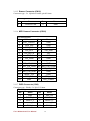
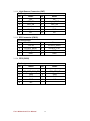
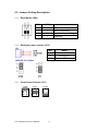
1
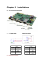
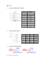
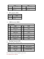
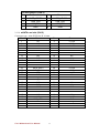
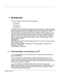
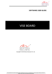
FA33 Motherboard SBC with Freescale iMX6 Dual Core Processor User Manual / Engineering Spec. Version 1.1 FCC Statement This device complies with part 15 FCC rules. Operation is subject to the following two conditions: This device may not cause harmful interference. This device must accept any interference received including interference that may cause undesired operation. This equipment has been tested and found to comply with the limits for a class "a" digital device, pursuant to part 15 of the FCC rules. These limits are designed to provide reasonable protection against harmful interference when the equipment is operated in a commercial environment. This equipment generates, uses, and can radiate radio frequency energy and, if not installed and used in accordance with the instruction manual, may cause harmful interference to radio communications. Operation of this equipment in a residential area is likely to cause harmful interference in which case the user will be required to correct the interference at him own expense. FA33 Motherboard User Manual I Copyright Notice No part of this document may be reproduced, copied, translated, or transmitted in any form or by any means, electronic or mechanical, for any purpose, without the prior written permission of the original manufacturer. Trademark Acknowledgement Brand and product names are trademarks or registered trademarks of their respective owners. Disclaimer We reserve the right to make changes, without notice, to any product, including circuits and/or software described or contained in this manual in order to improve design and/or performance. We assume no responsibility or liability for the use of the described product(s), conveys no license or title under any patent, copyright, or masks work rights to these products, and makes no representations or warranties that these products are free from patent, copyright, or mask work right infringement, unless otherwise specified. Applications that are described in this manual are for illustration purposes only. Winmate Communication Inc. makes no representation or warranty that such application will be suitable for the specified use without further testing or modification. Warranty We warrant that each of its products will be free from material and workmanship defects for a period of one year from the invoice date. If the customer discovers a defect, We will, at its option, repair or replace the defective product at no charge to the customer, provided it is returned during the warranty period of one year, with transportation charges prepaid. The returned product must be properly packaged in its original packaging to obtain warranty service. If the serial number and the product shipping data differ by over 30 days, the in-warranty service will be made according to the shipping date. In the serial numbers the third and fourth two digits give the year of manufacture, and the fifth digit means the month (e. g., with A for October, B for November and C for December). For example, the serial number 1W11Axxxxxxxx means October of year 2011. FA33 Motherboard User Manual II Declaration Note! Winmate Products are shipped without root access to Android operating system. However, Winmate can provide support for access upon special request by contacting Winmate Sales Caution! Rooting is a process that allows users to attain root access to the Android Operating System Code. It gives users privileges to modify the software code on the device or install any software without any permission. Any modifications to the system that could result in accidents where device can become beyond repair. Gaining root access also entails circumventing the security restrictions put in place by the Android operating system FA33 Motherboard User Manual III Packing List Before using this Motherboard, please make sure that all the items listed below are present in your package: FA33 Motherboard User Manual If any of these items are missing or damaged, contact your distributor or sales representative immediately. Customer Service We provide service guide for any problem as follow steps: The first, contact with your distributor, sales representative, or our customer service center for technical support if you need additional assistance. You may have the following information ready before you call: Product serial number Peripheral attachments Software (OS, version, application software, etc.) Description of complete problem The exact wording of any error messages In addition, free technical support is available from our engineers every business day. We are always ready to give advice on application requirements or specific information on the installation and operation of any of our products. Please do not hesitate to call or e-mail us. FA33 Motherboard User Manual IV Safety Precautions Warning! Always completely disconnect the power cord from your chassis whenever you work with the hardware. Do not make connections while the power is on. Sensitive electronic components can be damaged by sudden power surges. Only experienced electronic personnel should open the PC chassis. Caution! Always ground yourself to remove any static charge before touching the CPU card. Modern electronic devices are very sensitive to static electric charges. As a safety precaution, use a grounding wrist strap at all times. Place all electronic components in a static-dissipative surface or static-shielded bag when they are not in the chassis. FA33 Motherboard User Manual V Safety and Warranty 1. 2. 3. 4. 5. 6. 7. 8. 9. 10. 11. 12. 13. 14. 15. Please read these safety instructions carefully. Please keep this user's manual for later reference. Please disconnect this equipment from any AC outlet before cleaning. Do not use liquid or spray detergents for cleaning. Use a damp cloth. For pluggable equipment, the power outlet must be installed near the equipment and must be easily accessible. Keep this equipment away from humidity. Put this equipment on a reliable surface during installation. Dropping it or letting it fall could cause damage. The openings on the enclosure are for air convection. Protect the equipment from overheating. DO NOT COVER THE OPENINGS. Make sure the voltage of the power source is correct before connecting the equipment to the power outlet. Position the power cord so that people cannot step on it. Do not place anything over the power cord. All cautions and warnings on the equipment should be noted. If the equipment is not used for a long time, disconnect it from the power source to avoid damage by transient over-voltage. Never pour any liquid into an opening. This could cause fire or electrical shock. Never open the equipment. For safety reasons, only qualified service personnel should open the equipment. If any of the following situations arises, get the equipment checked by service personnel: A. The power cord or plug is damaged. B. Liquid has penetrated into the equipment. C. The equipment has been exposed to moisture. D. The equipment does not work well, or you cannot get it to work according to the user’s manual. E. The equipment has been dropped and damaged. F. The equipment has obvious signs of breakage. Do not leave this equipment in an uncontrolled environment where the storage temperature is below -40° C (-40°F) or above 70° C (157° F). It may damage the equipment. FA33 Motherboard User Manual VI Revision History Version Date 1.0 2015.04.13 1.1 changed to 2015.09.01 dualCPU core FA33 Motherboard User Manual Note First Release VII Author Jimmy Chen Jimmy Chen Contents Chapter 1 General Information ....................................................................... 2 1.1 Introduction..................................................................................................... 2 1.2 Feature ............................................................................................................ 2 1.3 Motherboard Specifications ............................................................................. 3 1.4 Function Block ................................................................................................. 4 1.5 Platform Descriptions....................................................................................... 5 1.5.1 Summary ........................................................................................................................... 5 1.5.2 System Memory: 1.35V DDR3L SDRAM ............................................................................ 5 1.5.3 LAN Chip: AR8031 integrated 10/100/1000 Mbps Ethernet Transceiver ......................... 5 1.5.4 HD Audio Codec: WM8962 Ultra-Low Power Stereo CODEC with Audio Enhancement .. 5 Chapter 2 2.1 Installations.................................................................................... 7 I/O Connector Description ................................................................................ 7 2.1.1 DC Jack (CN24) Power Conn (CN29) ........................................................................ 7 2.1.2 D-Sub 9 COM Port (CN27 & CN28).................................................................................... 8 2.1.3 External USB 2.0 (CN21) ................................................................................................... 8 2.1.4 Speaker Out (CN12 & CN14) ............................................................................................. 8 2.1.5 MIC connector (CN10) ...................................................................................................... 9 2.1.6 HDMI Connector (HDMI 1) ............................................................................................... 9 2.1.7 Backlight Connector (JP2) ................................................................................................. 9 2.1.8 LVDS connector (CN4) ..................................................................................................... 10 2.1.9 Internal USB 2.0 Connector (USB 1 , USB 2) ................................................................... 10 2.1.10 mSATA card slot (CN15) .............................................................................................. 11 2.1.11 RJ45 POE connector (LAN1) ....................................................................................... 12 2.1.12 Debug Connector (J1)................................................................................................. 12 2.1.13 CAN BUS Connector (CN3) ......................................................................................... 13 2.1.14 UART Connector (CN19) ............................................................................................. 13 2.1.15 Buzzer Connector (CN16) ........................................................................................... 14 2.1.16 MIPI Camera Connector (CON1) ................................................................................ 14 2.1.17 DIDO Connector (CN9) ............................................................................................... 14 2.1.18 Light Sensor Connector (CN7) .................................................................................... 15 2.1.19 SPI Connector (CN18) ................................................................................................. 15 2.1.20 OTG (CN32) ................................................................................................................ 15 2.2 Jumper Setting Description............................................................................. 16 FA33 Motherboard User Manual VIII 2.2.1 Boot Modes (SW1) .......................................................................................................... 16 2.2.2 Backlight power selector (JP2) ........................................................................................ 16 2.2.3 Panel Power Selector (JP1) ............................................................................................. 16 2.2.4 Brightness Adjust Mode Selector (JP4) ........................................................................... 17 FA33 Motherboard User Manual IX CHAPTER General Information 1 This chapter includes the FA33 Motherboard background information. Sections include: Introduction Feature Motherboard Specifications Function Block Board Dimensions FA33 Motherboard User Manual 1 Chapter 1 General Information 1.1 Introduction FA33 SBC is an integrated package that provides customers a complete RISC platform for project evaluation, application development and solution feasibility testing that decreases lead-time and lowers initial cost and investment. In peripheral connectivity, FA33 SBC features with two COM port, two USB 2.0 A-type connectors, one LAN port support PoE function, one DC input with Phoenix type terminal block, one Micro HDMI, one Micro SD card slot. 1.2 Feature 146 mm x 101 mm (3.5” Form Factor) Supports Freescale CortexTM – A9 iMX6 Dual Core 1GHz processor (Optional for Quad Core) Android 4.4 / Linux supported LVDS interface by pin-header 1 x RJ-45 10/100/1000 LAN (Optional for PoE function) 2 x USB 2.0 A-type 1 x Micro SD Card Slot 1 x USB OTG 1 x Micro HDMI 1 x I2C touch supported(by pin-header) 1 x Digital I/O with 3.3V (8-PIN GPIO) 1 x CANbus by pin-header (non-isolation)-optional 1 x Reset by Pin-header (optional for reset button) FA33 Motherboard User Manual 2 1.3 Motherboard Specifications CPU Type CPU Speed LCD interface LAN Memory Type Storage Freescale Cortex A9 iMX6 Dual Core (optional for Quad Core) 1 GHz LVDS interface 10/100 /1000 (Optional for PoE) 1GB DDR3 On Board 16GB eMMC /mSATA 1 x 2.5Ø DC Jack 2 x USB A-type (Host) 2 x RS232/422/485 selectable External I/O 1 x RJ-45 10/100/1000 (Optional for PoE function) 1 x Micro SD Card Slot 1 x Micro HDMI 1 x USB OTG 1 x LVDS by pin-header 1 x I2C Touch by pin-header 4 x USB by 2 pin-header (4 x 2 pin) Internal I/O 1 x RS232/422/485 by pin-header 1 x CANbus by pin-header (non-isolation) (optional) 1 x Digital I/O with 5V (8-pin GPIO) 1 x Reset by pin-header (optional for Reset button) Dimensions 146 mm x 101 mm (3.5” form factor) Mechanical & environmental Operating temperature: -25 deg. C to 65 deg. C Operating Humidity: 10 ~ 90% Relative humidity, non-condensing Power Input DC IN 12V Power Consumption 3W FA33 Motherboard User Manual 3 1.4 Function Block FA33 Motherboard User Manual 4 1.5 Platform Descriptions 1.5.1 Summary Features Core Memory Storage L2 Cache IPU i.MX 6 Dual(Quad) Dual-Lite Cortex-A9 1GB DDR3 16G eMMC/mSATA/Micro SSD (up to 64GB) 1 MB unified I/D L2 cache, shared by quad core Two autonomous and independent IPUs Three independent, integrated graphics processing units: Graphics acceleration OpenGL ® ES 2.0 3D graphics accelerator with four shaders 2D graphics accelerator Dedicated OpenVGtm 1.1 accelerator 1.5.2 System Memory: 1.35V DDR3L SDRAM 1.5.3 LAN Chip: AR8031 integrated 10/100/1000 Mbps Ethernet Transceiver 1.5.4 HD Audio Codec: WM8962 Ultra-Low Power Stereo CODEC with Audio Enhancement FA33 Motherboard User Manual 5 CHAPTER Installations 2 This chapter provides information on how to use the jumps and connectors on the FA33 Motherboard. The Sections include: I / O Connector Description Jumpers Setting Description FA33 Motherboard User Manual 6 Chapter 2 Installations 2.1 I/O Connector Description 2.1.1 DC Jack (CN24) Power Conn (CN29) CN24 CN29 Pin No SYMBOL Pin No SYMBOL 1 VIN 1 VIN 2 GND 2 VIN 3 GND 3 GND 4 GND FA33 Motherboard User Manual 7 ※ VIN:12V 2.1.2 D-Sub 9 COM Port (CN27 & CN28) Pin No SYMBOL 1 DCD 2 SIN 3 SOUT 4 DTR 5 GND 6 DSR 7 RTS 8 CTS 9 RI(5V) 10 GND 11 GND 2.1.3 External USB 2.0 (CN21) Pin No Symbol Pin No Symbol 1 5V 7 DP 2 DM 8 GND 3 DP 9 GND 4 GND 10 GND 5 5V 11 GND 6 DM 12 GND 2.1.4 Speaker Out (CN12 & CN14) FA33 Motherboard User Manual 8 CN12 Pin No CN14 SYMBOL Pin No SYMBOL 1 ROUT+_L 1 LOUT+_L 2 ROUT-_L 2 LOUT-_L 2.1.5 MIC connector (CN10) Pin Assignment No Name 1 MIC_IN + 2 MIC_IN - 2.1.6 HDMI Connector (HDMI 1) Pin Assignment No Name No Name 1 HP_DET_OUT 2 NC 3 HDMI_D2P 4 GND 5 HDMI_D2M 6 HDMI_D1P 7 GND 8 HDMI_D1M 9 HDMI_D0P 10 GND 11 HDMI_D0M 12 HDMI_CLKP 13 GND 14 HDMI_CLKM 15 HDMI_CEC_OUT 16 GND 17 H_CLK_OUT 18 H_DAT_OUT 19 HDMI_5V 20 GND 2.1.7 Backlight Connector (JP2) Connector type: Wafer 7 PIN pitch 2.0 mm Pin Assignment No Name No Name 1 +BKLPWR 5 BRIGHTNESS 2 +BKLPWR 6 GND 3 +BKLPWR 7 Backlight enable 4 GND Refer to JP4 jumper setting for brightness mode select. FA33 Motherboard User Manual 9 2.1.8 LVDS connector (CN4) Connector Type : DF13 20pin pitch 1.25mm Pin Assignment No Name No Name 1 LCDVDD 2 LVDS0_TX0_N 3 LCDVDD 4 LVDS0_TX0_P 5 LCDVDD 6 LVDS0_TX1_N 7 GND 8 LVDS0_TX1_P 9 GND 10 LVDS0_TX2_N 11 GND 12 LVDS0_TX2_P 13 GND 14 LVDS0_CLK_N 15 GND 16 LVDS0_CLK_P 17 GND 18 LVDS0_TX3_N 19 GND 20 LVDS0_TX3_P 21 GND 22 LVDS1_TX0_N 23 GND 24 LVDS1_TX0_P 25 GND 26 LVDS1_TX1_N 27 GND 28 LVDS1_TX1_P 29 GND 30 LVDS1_TX2_N 31 GND 32 LVDS1_TX2_P 33 GND 34 LVDS1_CLK_N 35 GND 36 LVDS1_CLK_P 37 GND 38 LVDS1_TX3_N 39 GND 40 LVDS1_TX3_P 41 GND 42 GND 43 NC 44 NC 2.1.9 Internal USB 2.0 Connector (USB 1 , USB 2) Connector type : 2*4p Wafer, P:2.0mm Pin Assignment (USB 1) No Name No Name 1 VUSB_VBUS5 2 VUSB_VBUS4 3 USB_PN5 4 USB_PN4 5 USB_PP5 6 USB_PP4 7 GND 8 GND FA33 Motherboard User Manual 10 Pin Assignment (USB 2) No Name No Name 1 VUSB_VBUS3 2 VUSB_VBUS2 3 USB_PN3 4 USB_PN2 5 USB_PP3 6 USB_PP2 7 GND 8 GND 2.1.10 mSATA card slot (CN15) Connector type : mini-PCIE slot, H: 6.8mm No Name No Name 1 3 5 7 9 11 13 15 17 19 21 23 25 27 29 31 33 35 37 39 41 43 45 47 49 51 m1 m2 NC NC NC NC GND NC NC GND NC NC GND SATA_RXP1 SATA_RXN1 GND GND SATA_TXN1 SATA_TXP1 GND GND +V3.3S +V3.3S GND NC NC SSD_LED# NC GND GND 2 4 6 8 10 12 14 16 18 20 22 24 26 28 30 32 34 36 38 40 42 44 46 48 50 52 m1 m2 +V3.3S GND +V1.5S NC NC NC NC NC GND NC NC +V3.3S GND +V1.5S NC NC GND NC NC GND NC NC NC +V1.5S GND +V3.3_3G GND GND FA33 Motherboard User Manual 11 2.1.11 RJ45 POE connector (LAN1) Pin Assignment (FAN1) No Name No Name 1 TRCT3 2 MDI2- 3 MDI2+ 4 MDI1+ 5 MDI1- 6 GND 7 TRCT4 8 MDI3+ 9 MDI3- 10 MDI0- 11 MDI0+ 12 TRCT1 13 PoE_A1+ 14 PoE_A1- 15 PoE_A2+ 16 PoE_A2- 17 LAN1_1000_O 18 LAN1_100_10_G 19 GND 20 LAN1_ACTIVE_Y 21 GND 22 GND 23 NC 24 NC Internal COM (CN1) No Name No Name 1 IO_DCDC# 2 IO_DSRC# 3 IO_SINC 4 IO_RTSC# 5 IO_SOUTC 6 IO_CTSC# 7 IO_DTRC# 8 IO_RIC# OR 5V 9 GND 10 GND 2.1.12 Debug Connector (J1) Pin Assignment No Name 1 NC 2 NC 3 TXD233 4 NC 5 NC 6 RXD232 7 DBUG_VBUS 8 GND FA33 Motherboard User Manual 12 On / Off Connector (CN22) No Name 1 NC 2 CPUPWRON 3 GND 4 GND 5 GND 6 GND 1 NC 2 CPUPWRON Reset Connector (CN25) No Name 1 +V3.3S 2 PWRON 3 GND 4 GND 5 GND 6 GND 2.1.13 CAN BUS Connector (CN3) Pin Assignment No Name No Name 1 +V_CAN_A 2 CAN1_RX 3 CAN1_TX 4 GND 5 GND 6 GND 2.1.14 UART Connector (CN19) Pin Assignment No Name No Name 1 VUART 4 GND 2 UARTTXD 5 GND 3 UARTRXD 6 GND FA33 Motherboard User Manual 13 2.1.15 Buzzer Connector (CN16) Connector type : 2 x 10pin box header, pitch 2.0mm Pin Assignment No Name No Name 1 +v12s or +v5s 2 GND 2.1.16 MIPI Camera Connector (CON1) Pin Assignment No Name No Name 1 LED_FLASH+ 2 GND 3 GEN_2V8 4 GND 5 GEN_2V8 6 GND 7 CSI_SCL 8 CSI_SDA 9 CSI_RST_B 10 NC 11 GND 12 GND 13 CSI_PWN 14 GND 15 GND 16 MIPI_CSI_D1P 17 MIPI_CSI_D1M 18 GND 19 MIPI_CSI_CLKP 20 MIPI_CSI_CLKM 21 GND 22 MIPI_CSI_D0P 23 MIPI_CSI_D0M 24 GND 25 MCLK_1V8 26 GND 27 GEN_2V8 28 GEN_1V8 29 GND 30 LED_FLASH- 2.1.17 DIDO Connector (CN9) Connector type : Header 2 x 5pin, P:2.0mm Pin Assignment No Name No Name 1 GND 2 DIO +5V 3 DOUT3_L 4 DOUT1_L 5 DOUT2_L 6 DOUT0_L 7 DIN3_L 8 DIN1_L 9 DIN2_L 10 DIN0_L FA33 Motherboard User Manual 14 2.1.18 Light Sensor Connector (CN7) Pin Assignment No Name No Name 1 +5V 2 NC 3 LED_B# 4 Light_PWR 5 LED_R# 6 LED_G# 7 GND 8 LS_DATA 9 LS_CLK 10 GND 11 NC 12 INT 2.1.19 SPI Connector (CN18) Pin Assignment No Name No Name 1 +V3.3S 2 ECSPI3_MISO 3 ECSPI3_MOSI 4 ECSPI3_CS1 5 ECSPI3_SCLK 6 GND 7 GND 8 GND 2.1.20 OTG (CN32) Pin Assignment No Name No Name 1 VUSB_VOTG 2 USB_OTG_CON_DN 3 USB_OTG_CON_DP 4 USB_OTG_ID 5 GND 6 GND 7 GND 8 GND 9 GND 10 NC 11 NC FA33 Motherboard User Manual 15 2.2 Jumper Setting Description 2.2.1 Boot Modes (SW1) PIN1 PIN2 0 0 Boot from fuses (default) 0 1 Serial downloader 1 0 Boot from board settings 1 1 Reserved 2.2.2 Backlight power selector (JP2) NO 1 2 3 2.2.3 Panel Power Selector (JP1) 3.3Volts 5Volts 12Volts 1 2 1 2 1 2 3 4 3 4 3 4 5 6 5 6 5 6 FA33 Motherboard User Manual 16 Name VIN INVERTER +V5S 2.2.4 Brightness Adjust Mode Selector (JP4) FA33 Motherboard User Manual 17