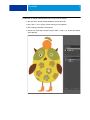
Download Cut contours - Fiery Help documents

Transcript
CUT CONTOURS
1
CUT CONTOURS
This document describes how to:
• Create cut contours in Adobe Illustrator® CS6
• Set up contour cutting in Fiery XF
• Set up ESKO i-cut for *.cut and *.ai files generated in Fiery XF
• Send cut files to the cut computer
For information on using print-and-cut devices, see the Fiery XF online user manual.
Preparing cut contours in Adobe Illustrator® CS6
Adobe Illustrator provides a number of methods for generating cut contours. Use the tools
that you are most comfortable with to draw contours around your image(s). If you are cutting
around a vector image, you can use the vector contours to create your outline. You can also
import cut contours that were created in a different application, such as Adobe Photoshop®.
It is important to align the cut contours to the print image when combining print-and-cut
information from multiple sources. By aligning cut contours, you can prevent incorrect
registrations during the cutting process.
The quality of your cut contours directly affects the cutting results, so it is a good idea to
carefully inspect your work before sending it to Fiery XF.
Good cut contours are smooth vector lines that wrap perfectly around both simple and
complex areas without any unnecessary details. Cut contours should always contain the
smallest amount of data necessary to produce the result that you are trying to achieve.
Poor cut contours contain thousands of tiny movements that reduce the performance and
quality of the cutting process. They are often the result of a raster-to-vector conversion. They
may also contain poor registration in critical areas, stray points, unnecessary paths, and paths
that overlap each other. If you are using a bitmap-to-vector conversion tool to create cut
contours, make sure that you check the result and perform the necessary clean-up before
sending the file to Fiery XF.
To set up cut contours in Illustrator, you must:
• Create a separate layer for the cut contour
• Assign a stroke thickness and a spot color to the cut contour
CUT CONTOURS
2
TO CREATE THE CUT CONTOUR LAYER AND ASSIGN A SPOT COLOR TO THE CUT CONTOUR
1 Open your vector art work in Adobe Illustrator, and click Select All.
2 Press <cmd> + <C> to copy the content of the layer to the clipboard.
3 Make a new layer and name it “Cut Contour”.
4 Keep the cut contour layer selected, and press <Shift> + <cmd> + <V> to paste the contents
of the clipboard.
CUT CONTOURS
5 Switch the visibility of layer1 to Off.
6 Open Pathfinder and click Unite to make sure you have a closed contour.
3
CUT CONTOURS
4
7 Enter a stroke thickness of 0.25pt.
8 Select a stroke color, and set the fill color to None.
Fiery XF uses spot colors to identify cut contours. It is useful to define spot colors for the
most commonly used cut contour names and to save them in a custom swatch library. The
following default names are supported in Fiery XF:
• Regmark
• Crease
• Kiss Cut
• Laser Cut
• Pen plot
• Router Cut
• Score
• Through Cut
• CutContour
• Die line
When the print file is imported into Fiery XF, the cut contours are extracted from the EPS or
PDF file to generate the cut path information.
You can also define custom spot colors to describe cut paths and add them to the list of
default names in Fiery XF. For more information, see “Setting up contour cutting in
Fiery XF” on page 5.
9 Open Attributes and select Overprint Stroke.
CUT CONTOURS
5
10 Switch the visibility of Layer1 back on.
11 On the File menu, click Save As, and save the file to EPS or to PDF format.
If you save to EPS, make sure to save the file with PostScript language level3.
If you choose PDF, select the “Preserve Illustrator Editing Capabilities” check box in the Save
Adobe PDF dialog box.
Setting up contour cutting in Fiery XF
TO CREATE A WORKFLOW FOR CONTOUR CUTTING IN FIERY XF
1 Make sure that the Fiery XF server is running, start the Fiery XF client and open
System Manager.
You need administrative rights to open System Manager.
2 Create a workflow for contour cutting.
Fiery XF provides some workflow templates especially for contour cutting.
• Contour Cutting
For all plotters supported by the Cut Server Option, and all i-cut-driven devices.
• Zund Cut Center Connectivity
Supports all Zund G3/S3 devices and enables direct communication through the network
to the ZCC software.
CUT CONTOURS
6
By default, both templates are set up to process jobs using the Adobe PostScript 3 Engine
(CPSI). CPSI is necessary to print jobs with cut contours.
If desired, you can change the workflow setting to use the Adobe PDF Print Engine (APPE).
APPE has certain advantages over CPSI when printing PDF or composite jobs. If APPE is
selected and you print a job that contains cut contours, the print engine switches
automatically to the following setting:
• CPSI (Fiery XF 6.2)
• FAST RIP (Fiery XF 6.2 for proServer)
For more information on the use of print engines in Fiery XF, see the Fiery XF online help.
If you prefer to create your own contour cutting workflow, it is recommended that you make
the following settings in System Manager:
• On the Workflow tab, open the Preview pane, and set the preview to 72 dpi.
• On the Workflow tab, open the Speed pane, and set the RIP resolution to “High quality”.
• On the File tab, open the PS/EPS/PDF pane, and set in-RIP separation to “Force”.
3 On the Finishing tab, open the Cut pane, and select the cut device. Then, make the following
settings, as appropriate:
• Cut marks color
Cut marks can be difficult to detect on some media types. The available settings let you
print cut marks in a color that is best suited to the color of your media.
White cut marks ensure that the cutter’s optical sensor can correctly detect cut marks on
non-white media. To print white cut marks, you require a printer with white ink and a
cutter that is supported in the Cut Marks option. White cut marks are previewed in light
gray.
Note that you cannot print white cut marks by selecting white as the line color in the color
selector window.
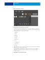
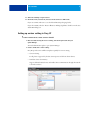
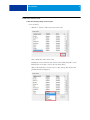
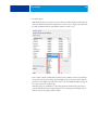
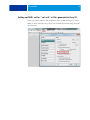
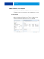
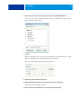
CUT CONTOURS
7
• Print between layout elements
This setting is required if i-cut is your device manufacturer and you want to output your
jobs as nestings or step & repeats. Selecting the check box ensures that additional marks
are placed between the elements of a nesting or a step & repeat job.
• Bleeding
The default setting is 0.
This setting should be applied only to level1 cut contours that are based on the bounding
box. Applying a bleed value to level 2 cut contours that have been created in pre-press
could cause the cut contours to be cut off.
Entering a value changes the size of the bounding box that is used to generate the cut file.
The size of the bounding box increases if you select “Add frame”. It decreases if you select
“Cut image”.
It can be useful to enter a bleed value for “Cut image” to remove bleed that was defined in
the artwork.
• Export path
Select the folder to which the cut files are exported.
If you output cut data to a Zund G3/S3 device, you can set up an IP network connection.
• Contour cutting
Define the cut contour.
– The check box “Extract contour path from EPS/PDF” defines what information is used
to generate the cut data.
– Different contour sources and cutting methods are available, depending on the selected
cutting device. You can also cut a job according to its PDF box. By default, the
bounding box is used, The following page size definitions are available: bounding box,
crop box, bleed box, art box, trim box. In the “Contour source” column of the contour
colors table, click “Bounding Box”, and select a page size definition from the
drop-down list box. In the “Method” column, double-click the selected item. Then,
click the down arrow and click a different cutting method.
– If no spot color is available for level 2 cut contours, the bounding box is used to
generate the cut data.
– A scissor sign in front of a color indicates cut contours. If the job contains spot colors
for cut contours, select the check box to ensure that Fiery XF recognizes them as
contour colors to be extracted as cut data. Cut contours are not printed.
You can also add custom contour colors.
CUT CONTOURS
TO ADD CUSTOM CONTOUR COLORS
1 Make the following settings on the Cut pane.
• For i-cut devices
– Click the "+" button to add a custom cut contour color.
– Select a method for each contour source.
Defining the correct method for each contour source enables Fiery XF to create
different layers of cut data to send to the i-cut-driven device.
Click on the method for a contour source to edit it. A drop-down list box with
predefined methods is displayed.
8
CUT CONTOURS
9
If the method you want to use is not listed, click User defined to create one. The
Custom cut methods dialog box opens.
Click the “+” button to add a new row to the table. Then, enter the name of the
custom contour cut method by overwriting “Enter custom cut method name”. Click
the “+” button again to confirm, and then click OK. (If the OK button is not available,
select a different cut contour in the list and then reselect the new cut contour.)
The new cut contour method is added to the list of contour sources.
Repeat the process for all your standard contour sources.
CUT CONTOURS
10
• For Zünd devices
With Zünd G3/S3 types of plotters, you can select any standard method, as defined by the
device manufacturer. Click on the method for a contour source to display a drop-down list
box with predefined methods, and click the method you want to use.
In the “Mode” column, double-click “Standard”. Then, click the down arrow and click a
mode (optional). The mode affects speed and quality. The speed setting ensures that the
printout is cut as quickly as possible, but it may not be exact. With the quality setting, the
cut is more precise, but it takes longer.
Advanced settings are available for some cutting methods. Click the blue pen button to
open the Advanced contour settings dialog box. You can change the line length, the bit
diameter, the grooving angle, and the z depth.
CUT CONTOURS
11
Setting up ESKO i-cut for *.cut and *.ai files generated in Fiery XF
In the i-cut software, make sure that the check box “Move to (0.0) after Import” is cleared.
Failing to do this will result in the position of the cut marks/camera marks being offset with
the cut contours.
CUT CONTOURS
12
Sending cut files to the cut computer
To write cut files to the computer that is running the cut software, Fiery XF must have write
access.
The following procedure is for computers that are on the same subnet but not on a domain.
TO ALLOCATE WRITE ACCESS
1 Create a shared folder on the computer that is running the i-cut software.
Make sure that the folder is shared and that the group “Everyone” has full control. In the
example below, the shared folder is Win7_XF_6.0 and the user is named EFI.
CUT CONTOURS
13
2 In Fiery XF, type the path name of the shared folder as \\IP_Address\ShareName.
You do not need to map the drive from the Fiery XF side. Click Browse, and type the path
name in the Folder name edit box.
3 Click OK.
When you click OK, you are asked for login credentials for the shared folder. Enter a valid
user name and password for the computer with the i-cut software.
The export path is displayed in Fiery XF as shown below:
4 Exit the Fiery XF client and stop the server.
5 Right-click the Fiery XF Control icon, and click Fiery XF Server Conguration.
The Windows Services dialog box opens.
6 In the list, double-click EFI XF Server to open the Properties dialog box.
CUT CONTOURS
7 On the Log On tab, set the Fiery XF server service to log in with the same user name and
password as an authorized user on the computer that is running the i-cut software.
8 Click OK.
9 Restart the Fiery XF server and the Fiery XF client.
14