1
PlatePatcher
7.5
USER MANUAL
21.08.2009
PlatePatcher 7.5
2 / 31
Table of Contents
1
INTRODUCTION .......................................................................................................................................... 3
2
FIRST START-UP OF THE SOFTWARE ........................................................................................................... 3
2.1
ENTERING THE LICENSE KEY................................................................................................................................. 3
2.2
SETTING THE LANGUAGE..................................................................................................................................... 3
2.3
NETWORK CONFIGURATION ................................................................................................................................ 4
3
BASIC SETTINGS .......................................................................................................................................... 5
4
KONGSBERG XL-GUIDE 6046 ....................................................................................................................... 6
4.1
SETTING THE TOOLS ........................................................................................................................................... 6
4.2
ASSIGNMENT OF THE OUTPUT CHANNELS .............................................................................................................. 7
4.2.1
4.3
5
Output Channels of the PlatePatcher................................................................................................ 7
STARTING THE JOB............................................................................................................................................. 8
PLATEPATCHER ........................................................................................................................................... 9
5.1
OUTPUT DEVICES .............................................................................................................................................. 9
5.2
SETTING THE PLATEPATCHER OPTIONS ................................................................................................................ 10
5.2.1
5.2.2
5.2.3
5.2.4
Adding Settings ............................................................................................................................... 10
Changing Settings ........................................................................................................................... 10
Deleting Settings ............................................................................................................................. 11
Possible Settings.............................................................................................................................. 11
5.3
EDITING A JOB ................................................................................................................................................ 13
5.4
MULTI PATCH MODE ....................................................................................................................................... 19
5.5
AV FLEXOLOGIC .............................................................................................................................................. 20
5.5.1
Importing and Mounting................................................................................................................. 20
5.6
ZERO POINT FOR AV FLEXOLOGIC, MACROFLEX AND HEAFORD ................................................................................ 23
5.7
LOADING TIF FILES .......................................................................................................................................... 24
5.8
WRITING TIF FILES .......................................................................................................................................... 24
5.9
OUTPUT DIRECTORIES ...................................................................................................................................... 25
5.10
JOB INFORMATION .......................................................................................................................................... 25
6
OVERVIEW OF MOUNTING MARKS............................................................................................................26
7
HOT KEYS...................................................................................................................................................27
8
ACM VIEWER .............................................................................................................................................28
9
HOTLINES ..................................................................................................................................................30
PlatePatcher 7.5
1
3 / 31
Introduction
The "PlatePatcher" analyses the image content of LEN or TIF files and applies register
marks to the determined areas. A file with coordinates is created for automatic
mounting. A printout of an ACM or EPS file is used for manual mounting.
The "viewer" is used to display and measure the LEN/TIF files. The angle and the
rasterization can also be measured.
2
First Start-up of the Software
All important settings are copied over during an update.
2.1
Entering the License Key
During initial installation or when updating from an older version, the license key must
be entered to start the "Merger":
The ESKO-Service provides a serial number for this "ProductID" which needs to be
entered in the "Serial Number" field and confirmed by ENTER.
The license can be subsequently changed with the "New License" program in the
Windows start menu under "Esko - Digital Flexo Suite - System".
2.2
Setting the Language
The language can be changed with the "UI Language" program in the Windows start
menu under "Esko - Digital Flexo Suite - System".
PlatePatcher 7.5
2.3
4 / 31
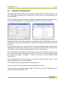
Network Configuration
The image data can be loaded from the local hard drive, over a network release, or via
FTP. With regard to data security, transmission via FTP protocol is to be preferred over
network release.
The "User Data" path entered during installation is already released as a network drive.
To set up additional drives, run the "guinet.bat" program in the c:\bsl\ui directory.
Clicking the field below "Drive" displays the registered drives. Selecting one of these
drives calls up the entered access data. In addition, the selected drive can be deleted or
changed.
After clicking on "New", the local drive letter on this drive is shown under "Disk" and the
subdirectory is shown under "Sub directory". The name of this drive link is entered in the
"Drive Name" field. The Merger later accesses this drive via this name.
The "FTP" option is activated for an FTP connection and the IP number or the computer
name of the FTP server is entered under "Host". The user name and the password must
be entered accordingly. In addition, a name for this link must be entered under
"Drive Name".
The user data for the FTP connection can be tested using the "Test" button. A new
window designated "Load Image" appears.
"OK" cancels the test and accepts the selected directory.
"Cancel" closes this window without making changes to the path.
The entered data is accepted using "Accept". "Quit" closes the drive configuration. Any
changes made are stored with "OK" .
PlatePatcher 7.5
3
5 / 31
Basic Settings
"Units" switches between "mm" and "inch".
"Digits" and "Post colon" set the amount of numbers and/or decimal points.
"Check Images before start" checks the images of all outgoing jobs.
"File Copy Method" sets the behavior while loading images. The "Copy" setting is used
to copy files, if "Move" is selected, the files are deleted from the source directory.
"Show Ruler" activates or deactivates the ruler. This setting affects the Merger.
"Plugin Selection": This is where you can activate or deactivate options for the Digital
Flexo Suite.
In the "Folder" window, the preset output directories can be changed.
The PlatePatcher must be restarted after any change.
PlatePatcher 7.5
4
6 / 31
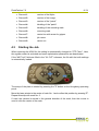
Kongsberg XL-Guide 6046
At least XL-Guide version 6061 must be installed:
If an ACM file created with XL CUT in XL-Guide 6061 is opened, the global setting is
automatically changed to "CTP Flexo". The cut and sequence optimization is
deactivated in this setting. To cut the plate properly, the 2-point registration "Register
Wizard" is automatically activated. In addition, the "Job setup" is loaded as indicated in
the "MAT Info" field.
The "Scale" has to be deactivated.
4.1
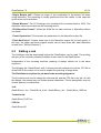
Setting the Tools
The knives can be set in the "Job setup" window which is opened via the "Options"
menu. Each element in the ACM file is assigned to its own channel (line) (1). The
speed and the acceleration (3) must be determined on site.
Since Digital Flexo Suite 7.5, the ACM file contains more channels which must be
selected at the Kongsberg table.
Therefore, the "No tool = Ignore" (2) option must be activated.
If the recommended vertical alignment of register marks has been set, "6" must be set
in the "Register mark positions" dialogue. For a horizontal alignment, "7" must be set.
PlatePatcher 7.5
4.2
7 / 31
Assignment of the Output Channels
Each element in the ACM file is assigned to its own channel (line). The channels cannot
be defined or hidden in the Digital Flexo Suite. This has the advantage that the operator
of the Kongsberg table can change the output quickly.
4.2.1 Output Channels of the PlatePatcher
Depending on the selected output device, the PlatePatcher uses up to nine channels.
Only the required channels are set up in the "Job setup" window. All other channels
must be set to "No Tool". In addition, the "No tool = Ignore" option must be activated.
PlatePatcher 7.5
4.3
8 / 31
• Channel 1:
contour of the Mylar
• Channel 2:
contour of the image
• Channel 3:
contour of the "patch"
• Channel 4:
labelling of the "patch"
• Channel 5:
labelling of the mounting mark
• Channel 6:
mounting mark
• Channel 7:
centre line with arrow for gripper
• Channel 8:
job name
• Channel 9:
carton cut
Starting the Job
When importing the ACM file, the setting is automatically changed to "CTP Flexo". Here,
the register wizard is activated and some optimisation parameters are deactivated.
If the "MAT Info" field was filled in the "XL CUT" submenu, the file with the knife settings
is automatically loaded.
The setup of the plate is started by pressing the "I" button on the Kongsberg operating
panel.
Move the laser pointer to the centre of mark No. 1 and confirm this position by pressing "I".
Repeat this step with mark No. 2.
If used, the camera is moved in the general direction of the mark, then the mouse is
used to click the centre of the mark.
PlatePatcher 7.5
5
9 / 31
PlatePatcher
opens the PlatePatcher in a new window.
The PlatePatcher automatically searches the LEN or TIF files for free areas to cut out
the remaining image content. Depending on the output device, the relevant files will be
created for subsequent mounting.
5.1
Output Devices
For digital mounting, a camera and a mounting file are used to mount the plate pieces
with mounting marks on the Mylar. The accuracy is very high.
For analogue mounting, a printout or mounting pins are used to manually mount the
plate pieces on the Mylar. The accuracy is low.
Digital output devices:
• "AV Flexologic"
round mounting and flat mounting possible
• "Macroflex"
flat mounting
• "Heaford"
flat mounting
Analogue output devices:
• "ACM PLOT"
cutting and labelling the Mylar
• "EPS PLOT"
film labelling
•
"Bieffebi"
film labelling using a special EPS format
PlatePatcher 7.5
5.2
10 / 31
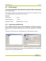
Setting the PlatePatcher Options
Templates can be created for the PlatePatcher options by calling up the "PlatePatcher"
under "Options / Workflow Editor…":
The "Workflow Editor" for the PlatePatcher can be divided into four areas:
1
Selection of the saved settings.
2
Options for the current selection.
3
Advanced options for the current selection.
4
Save, delete and create new settings.
5.2.1 Adding Settings
By selecting "New" (4), a new window appears in which you can enter a name for this
setting. "OK" confirms the input. The new setting is automatically selected.
Adjust the required settings and save them by pressing "Save" (4).
5.2.2 Changing Settings
Select the setting (1) and change it. Press "Save" (4) to save the setting.
To not lose existing settings, the new settings can be renamed by pressing "Save as" (4).
PlatePatcher 7.5
11 / 31
5.2.3 Deleting Settings
Select the setting (1) and delete it by pressing "Delete".
5.2.4 Possible Settings
Each mounting device can be adjusted individually. Before starting the device for
production, these properties must be set and checked during a test mounting. For this
purpose, a job which is unsymmetrical in X and Y direction is to be used.
"Default Frame": Minimum distance between the patch and the edge of the created
image. If this is set too small, a collision can occur during automatic grouping.
"Film Gap": Gap between the register mark and the edge of the image clip. This area is
also used for subsequent cuts using the 45° knife.
"Patch Distance": Defines the distance between two image elements by compiling
them automatically in one grouping. Elements with a larger distance are separated.
"Vertical Distance": Height above which additional register marks are added to the
patch.
"Plot Device": Sets the output format for the plotter. ACM is always available for the
output on the Kongsberg table, an EPS output is only possible with an extra license.
"Technical Ink": In order to be able to identify the technical ink (carton cut) later on, the
name must be determined according to the file name (e.g. filename_PLOT).
"MAT Info": As an option, the name of the XL-Guide "Job Setups" which will be
automatically loaded on the Kongsberg table can be entered in this field.
"Mount Target Folder": Is the folder where the mounting file is stored.
"Export - LEN / TIF": The resulting images are exported directly into directories instead
of transmitting them to the Merger. An extra licence is required to output TIFs.
"Emulsion down": Rotates the output coordinates by 180°.
PlatePatcher 7.5
12 / 31
"Top Grid": Mirrors the output coordinates in the circumference direction. This option
has to be activated when the image data is mirrored after patching, which is the case
with some other types of CtP exposure units.
For AV-Flexologic, "Emulsion down" and "Top Grid" must be activated since the
mounting is usually performed from above.
"Cut Mylar": Automatically cuts the Mylar on the Kongsberg table after the register
marks or mounting holes and the carton cut have been drawn. The LEN or TIF file must
correspond to the size of the Mylar. The design defines the position of the image data
on the Mylar. Depending on the plate distortion, the gripper distance and the Mylar
height are automatically counted back.
"Front Text": The patch labelling is not exposed together with the plate but craved into
the frame area using the knife on the Kongsberg table. This labelling needs not to be
removed afterwards.
"Crop Patches": If areas are grouped in different separations in multi patch mode, the
resulting patches are reduced to the required size. If this function is deactivated,
patches of the same size are created.
"Single Plot File": Creates a file with coordinates for each separation. If this function is
deactivated, all coordinates are written into one file.
"Mount Offset": With AV Flexologic, an upper and lower image border is inserted in
the grouping window. This is required when register marks must be positioned above or
below the image. The entire co-ordinate plane is moved by this value, which results in a
difference to the original gripper distance during the mounting.
"Pre-Mount Gap": Enlarges image sections in the mask for plate mounting when using
PreMount.
"Camera Distance": Determines the minimum camera distance for the selected
mounting device. A higher value creates wider patches.
"Font Size": Determines the size of the register mark labels.
"Register Mark File": You can select the mounting marks from a list. An overview can
be found in the appendix.
"Regmark Scale": Enlarges the mounting marks on the Mylar significantly.
"Add Job Name": Automatically inserts the file name under each patch.
"EPS Show Boxes": Creates a frame around each patch in the created EPS file.
"EPS-Text as Pathes": Converts text into vector data for the EPS file.
PlatePatcher 7.5
13 / 31
"Origin Bottom Left": Places the origin of the coordinates at the bottom left when
using Macroflex. The mounting is usually performed from the middle. In this case this
option must not be activated.
"Round Mounter": For AV Flexologic, the coordinate file is counted back to 100%. The
distortion values are entered on the mounting device.
"Old Macroflex Format": Writes the DHM file for older versions of Macroflex without
line break.
"Count Separations": Enumerates the separations in the Macroflex output file.
"Patch Multi-Line": Creates three lines in the Macroflex output file for each patch. In
this way, the upper and lower register marks can be used even with older Macroflex
models (see "Vertical Distance").
5.3
Editing a Job
The Hotfolder must be deactivated before the PlatePatcher can be used. The working
directory of the currently selected Hotfolder is also used for the PlatePatcher.
Independent of the mounting machine, patching is always carried out in the same
sequence.
The following job "GaelicGhost" with 4 colours plus the technical ink and the CF2 file of
ArtiosCAD for the carton cut is used to explain the patching of image data.
The PlatePatcher requires the job data in the mounting alignment.
The file names are used to assign the technical ink and the CF2 file to the job. As with
the Merger, the names may not include special characters. The ink designation may not
include spaces or underscores:
Job:
GaelicGhost_c.len - GaelicGhost_k.len - GaelicGhost_y.len - GaelicGhost_1605.len
Technical ink:
GaelicGhost_PLOT.len
CF2 file:
GaelicGhost.cf2
PlatePatcher 7.5
14 / 31
The start is carried out in the "Preview" mode. The Merger remains in the background
but cannot be used.
1
Select the mounting settings.
2
Load the job.
Select only one separation, then confirm it with "OK" or double-click the file
to load it. The other separations and control files are automatically copied
into the working directory and displayed.
PlatePatcher 7.5
3
15 / 31
Check if the technical ink "Plot File" and the CF2 file "Tool File" were
loaded. If these files are missing contrary to expectations, check the file
names.
By selecting "View…", the entire job is opened in the "Bitmap Viewer".
Clicking on "Clear" removes the images from the display, and the options
can be selected again. This step does not delete any data on the storage
medium.
4
Under "Separations" (4 ), the option "Single" is to be selected to patch
single separations. "Patch Radius" defines the distance between two image
elements by compiling them automatically in one grouping. Elements with a
larger distance are separated.
5
Select the separation. A preview is displayed in the main window.
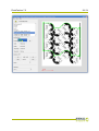
6
By selecting "Analyse image", the image is analysed and displayed in the
grouping window. You can also start the analysing process by doubleclicking the respective separation.
"Close" closes the PlatePatcher.
PlatePatcher 7.5
16 / 31
7
Clicking on the eye next to the ink in the table activates or deactivates the
display.
8
Several patches can be selected by pressing the "Ctrl" button and the left
mouse button simultaneously and then grouped by clicking on "Group" (12)
or "g".
Alternatively, you can also use the left mouse button to pull a lasso around
several "patches".
9
Overlaying plate pieces are marked in red and listed in the information
display (11).
10 Collisions of marks with image data are highlighted with an exclamation
mark. The patches can be created but the mounting marks will not be drawn
in order to not change the image content.
11 In the information field, "Total" shows the number of plate pieces and
"Saved" shows the area saved in cm² and as a percentage. In addition,
warnings will be displayed here informing you about overlays.
PlatePatcher 7.5
17 / 31
12 Marks can be moved subsequently. Clicking on the mounting mark once
changes the colour to yellow and a green frame is shown. The mark can be
move horizontally by holding down the left mouse button in the green frame.
Another click on the yellow mark changes the colour to red. The mark can
now be moved vertically with the left mouse button pressed on the mark.
The opposite mark is automatically moved simultaneously.
13 Hidden elements are marked.
14 "Ungroup" breaks a group down into its single elements.
"Jobname" is used to add the file name to the lower edge of the patch.
"Hide" or "x" hides one or more marked patches. This option can be used to
hide unnecessary elements.
"Add Mark" adds an additional mounting mark. "Remove" removes this
mark.
"Reset" sets the mounting marks for the marked patch back to their original
positions.
PlatePatcher 7.5
18 / 31
15 The distortion "Rip Scale" is automatically read from the LEN file. For TIF
files or if the distortion information is missing, the distortion is calculated
based on the size difference between the CF2 file and the technical ink. If
the information is indefinite, 100.0 is displayed as value but can be changed
manually.
With some mounting devices, "Mount Scale" can be used to scale the
output file.
"Rotate" rotates all output files by 90°.
"Negative" inverts all output files for film exposure units because negative
images cannot be edited in PlatePatcher.
The settings "Negative" and "Rotate" can only be changed in the first
separation and are then valid for the entire job.
16 "Create" cancels the grouping. The requested files are created and
transmitted to the Merger or a directory. This process may take several
minutes, depending on the complexity. Collisions of register marks with
image elements and overlays are displayed in a corresponding message
window. In general, no image data is overwritten.
"Close" closes the grouping view without creating files.
All separations are edited in sequence. Select the next separation (5) and repeat the
process. Mounting files are always updated when data is created so that all required
data is available at the end.
PlatePatcher 7.5
5.4
19 / 31
Multi Patch Mode
All separations are displayed and edited together. The selected base separation
"Master" is not cut and includes the register marks of all other separations after editing.
All other separations are based on this base separation on the mounting device at a
later time.
If "Multiple" is selected, the table with the separations extends:
"Master" selects the base separation from the loaded job. The master must still have
sufficient free space to allow the register marks of the other separations to be placed.
"Reference" selects a separation which is not to be cut. For mounting, mounting marks
are placed to the left and the right of the image.
"Patch" displays the separations which will be analysed.
Set the "Patch Distance" and open the grouping window by selecting "Analyse
image…".
The same editing options as in the "Single Patch Mode" are available.
As opposed to "single patching", collisions can now also occur on the "Master". As the
separations are still mounted separately, overlays between different separations no
longer occur.
Showing and hiding separations makes it easier to keep an overview when working on
complex jobs. The reference separation is labelled "(ref)", the master separation with
"Master".
PlatePatcher 7.5
5.5
20 / 31
AV Flexologic
To be able to place registry marks underneath or above the image, a lower or upper
edge is required respectively. This edge is set up with "Mount Offset" as described in
the mounting settings.
This creates an offset in circumferential direction which has to be subtracted from the
desired gripper distance (black area) for the mounting:
Example:
"Mount Offset":
20 mm
Desired black area:
100 mm
Required AV offset:
80 mm (100 mm – 20 mm)
5.5.1 Importing and Mounting
After the MOM file has been created with the PlatePatcher, the Optimount software is
used to import this file for mounting on the AV-Flexologic. The import of externally
created data is an additional-charge option which needs to be enabled by AV-Flexologic
first.
Clicking on "Job Editor" (1) and "Load" (2) opens the "Load Postscript" window.
"Import" (3) opens a dialog window in which the required MOM file can be selected and
another click on "Import" (7) loads this file.
PlatePatcher 7.5
21 / 31
Before loading this file, the "Plate Distortion" (6) and the "Mirror Options" (4) must be
set. If the options "Top Grid" and "Emulsion down" were selected in the PlatePatcher,
the option "No mirror" (4) must be selected here. "Close" (8) is used to close the
window.
"Search" (9) updates the database and displays the job that has been imported last.
"Close" (10) opens the "Job processing" window which displays all data. Another click
on "Close" (11) cancels the loading process.
The mounting device is started using "Home motors" (12). "Automatic mounting" (13)
displays the plate pieces to be mounted in a new window (15).
Each mounting mark on the plate has a number which is displayed under "Group" (16)
on the software.
PlatePatcher 7.5
22 / 31
In addition, only the left mounting marks have a letter to identify the correct separation.
In the overview, this side with the letters is indicated with a slanted mark (14) so the
plate piece can be mounted and aligned correctly.
"Mount" (17) moves the cameras and the drum to the mounting position. This process is
carried out for all plate pieces in this separation and is completed with "Close" (18).
The left camera (19) is used to precisely position the plate. The right camera (20) can
slightly differ from the theoretical position so only the horizontal line on the mark is used
to set up the plate.
In the overview window, the next separation can now be selected with "Next" (21) and
the mounting is carried out again with "Automatic mounting" (22).
PlatePatcher 7.5
5.6
23 / 31
Zero Point for AV Flexologic, Macroflex and Heaford
The PlatePatcher places the zero point in the bottom left corner of the ripped LEN or
TIF file. If, in addition, job information and screen wedges are set in the customer's job,
an offset to the desired zero point is created in the X and Y directions. In most cases,
this offset is varies, which may lead to incorrect mounting.
The required zero point (1) is moved in the wrong design (3). In addition, the screen
wedge outside the image width displaces the mounting centre (2). This can be avoided
by extending the image symmetrically to both sides.
PlatePatcher 7.5
5.7
24 / 31
Loading TIF Files
TIF files are normally read from left to right. Because of the technical requirements of
imaging, Digital Flexo Suite reads TIF files from the bottom to the top. This rotates the
display accordingly:
The alignment of the images in PlatePatcher has to match the alignment in mounting.
The image has to be rotated 90° in the design for exporting.
5.8
Writing TIF Files
TIF files can be exported directly from PlatePatcher using the TIF export function. The
TIF data is exported with the alignment as described in the previous chapter which
results in a rotated display in other programs.
The software of some of the CTP exposure units available on the market displays the
TIF data with the same alignment as in the design, even though the data has to be read
from the bottom to the top for imaging.
This is caused by the different alignment between drum and image. The Merger
assumes that the height corresponds to the circumference of the drum and the width
corresponds to the width of the drum. The drum may be shown rotated by 90° in the
displays of other CTP exposure units.
PlatePatcher 7.5
5.9
25 / 31
Output Directories
In order to output mounting and preview files, the PlatePatcher needs predefined
directories.
The mounting settings can be called up under "Options – Preferences – Folder" in the
Merger.
"Preview Target Folder": A preview file ("Preview") in TIF format is created for every
edited separation.
"LEN Target Folder" – "TIF Target Folder": Depending on the license or when
"Export – LEN/TIF" is selected, the LEN or TIF files are saved in these directories.
5.10 Job Information
An HTML file with the original file name is stored in the "Preview" directory for every job.
All important information concerning the job is stored in that directory. The output
directory "d:\files\output\preview" is preset.
PlatePatcher 7.5
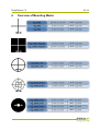
6
Overview of Mounting Marks
26 / 31
PlatePatcher 7.5
7
27 / 31
Hot Keys
Merger
load file
Strg / Ctrl + O
remove file
Strg / Ctrl + X
remove all positioned images
Strg / Ctrl + D
Select Working Folder
Strg / Ctrl + W
Load Plate...
Strg / Ctrl + L
New Plate...
Strg / Ctrl + N
Save Plate
Strg / Ctrl + S
terminate merger
Strg / Ctrl + Q
send job
Strg/Ctrl + E
Automatic Positioning of the Images
Strg / Ctrl + A
automatically position new images
Strg / Ctrl + H
remove all images from the working surface
Strg / Ctrl + U
*store template
Strg / Ctrl + Y
*use template
Strg / Ctrl + V
*modify template
Strg / Ctrl + M
*edit template
Strg / Ctrl + K
Print Job Info...
Strg / Ctrl + P
print working surface
Strg / Ctrl + Z
Group
Strg / Ctrl + G
Hide
Strg / Ctrl + X
PlatePatcher
PlatePatcher 7.5
8
28 / 31
ACM Viewer
This program is used to display and control the ACM files which were created by using
the Digital Flexo Suite.
After the Digital Flexo Suite installation, all ACM files are automatically linked to the
"ACM Viewer" .
The distance between two points can be measured by using the right mouse button
(hold pressed)(1). The image content can be enlarged by using the mouse wheel (2)
and moved by using the left mouse button (hold pressed and pull) (3).
Double-click one ACM file and an additional window (4) will be opened. "Start" in the
"Manual Step" area (5) starts a simulation of the cutting and drawing process. In the
"Settings" area (6), the line thickness can be changed.
Additional information can be displayed in the "View" menu.
If the ACM Viewer of the Digital Flexo Suite is used, LEN files can also be displayed.
Cutting information of "Staggered Cut" and CAD information of Flexrip are displayed in
addition.
PlatePatcher 7.5
29 / 31
PlatePatcher 7.5
9
Hotlines
30 / 31
PlatePatcher 7.5
31 / 31
© Copyright 2009
Esko-Graphics Imaging GmbH, 25524 Itzehoe, Germany
Esko-Graphics A/S, 8520 Lystrup, Denmark
All rights reserved. This document and all information and instructions contained within
are the property of Esko-Graphics. These documents contain the product descriptions
according to their current state at the time of publication, but no responsibility
whatsoever is taken for the correctness of this information. No guarantees are granted
or expanded upon by this document. Furthermore, Esko-Graphics does not guarantee
the illustrations relating to the usage of the products, or for the results from using the
software or the use of the information contained herein. Esko-Graphics is not
responsible for direct or indirect damages caused by the logical consequences or latent
damages which may result from the use of the software, or from the impossibility of
software use or of the information contained herein.
The technical data contained herein and the content of this manual are subject to
change without prior notification. Revisions which point out such changes and/or
supplements may be issued from time to time.
Without express written consent, no part of this document may be reproduced,
transferred, electronically stored or published, irrespective of the reasons and
irrespective of the method or means used, i.e. electronic, mechanical, by printing,
microfilm, etc.
These documents replace all previous versions.
Grapholas® is a registered trademark of Esko-Graphics Imaging GmbH.
This product is protected by the following US patents: 6,985,261 / 6,954,291
Cyrel®, Cyrel® Digital Imaging System and Cyrel® Digital Imager are registered
trademarks of DuPont.
Microsoft and the Microsoft Logo are registered trademarks of Microsoft Corporation in
the USA and other countries.
Esko-Graphics software may include the "RSA Data Security, Inc. MD5 Message-Digest
Algorithm".
All other product names are trademarks or registered trademarks of their respective
owners.