1
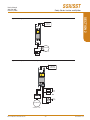
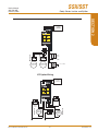
Demand Moore Reliability
SSX / SST Safety Series Isolator and Splitter
SSX/SST
Safety Series Isolator and Splitter
User’s Manual
206-792-00E
Febuary 2015
www.miinet.com
SSX/SST
User’s Manual
206-792-00E
February 2015
Customer Support
Safety Series Isolator and Splitter
Demand Moore Reliability
Customer Support
Moore Industries is recognized as the industry leader in delivering top quality to its customers in products
and services. We perform a sequence of stringent quality assurance checks on every unit we ship. If any
Moore Industries product fails to perform up to rated specifications, call us for help. Our highly skilled staff of
trained technicians and engineers pride themselves on their ability to provide timely, accurate, and practical
answers to your process instrumentation questions. Our headquarters and other facilities phone numbers
are listed below.
There are several pieces of information that can be gathered before you call the factory that will help our
staff get the answers you need in the shortest time possible. For fastest service, gather the complete model
and serial number(s) of the problem unit(s) and the job number of the original sale.
Locations
World Headquarters
Europe
Australia
16650 Schoenborn Street
North Hills, California
91343-6196, U.S.A.
Tel: (818) 894-7111
Fax: (818) 891-2816
E-mail: [email protected]
TOLL FREE: 1-800-999-2900
www.miinet.com
1 Lloyds Court, Manor Royal,
Crawley
W. Sussex RH10-9QU
United Kingdom
Tel: 01293 514488
Fax: 01293 536852
FREE PHONE: 0800 525107
[email protected]
www.miinet.com/uk
Sydney, NSW
3/1 Resolution Drive
Caringbah, New South Wales
2229
Australia
Tel: (02) 8536-7200
Fax: (02) 9525-7296
[email protected]
www.miinet.com/au
Drie Eikenstraat 362
B-2650 Edegem
Belgium
Tel: 03/448.10.18
Fax: 03/440.17.97
[email protected]
Dutch: www.miinet.com/dbe
French: www.miinet.com/fbe
Perth, WA
6/46 Angove Street
North Perth, Western Australia
6006
Australia
Tel: (08) 9228-4435
Fax: (08) 9228-4436
[email protected]
www.miinet.com/au
China
Room 806, Block 2,
Lotus International Plaza
No. 7866 Hu Min Road,
Min Hang District,
Shanghai, 201102, P. R. China
Tel: 86-21 62491499
Fax: 86-21 62490635
E-mail: [email protected]
www.miinet.com/cn
Burg Meslaan 98
4003 CD Tiel
The Netherlands
Tel: (0)344-617971
Fax: (0)344-615920
[email protected]
www.miinet.com/nl
www.miinet.com
www.miinet.com
-2-
Moore Industries-International, Inc.
SSX/SST
User’s Manual
206-792-00E
February 2015
Safety Series Isolator and Splitter
About this Manual
Safety Messages
Please read this manual in its entirety. It should answer most of your questions. For personal and system safety, and for
optimum product performance, make sure you thoroughly understand the contents before installing, using, or maintaining
this product. Should you still have questions please visit our web site at www.miinet.com or contact any of our sales/
support offices nearest you.
Your safety and the safety of others is very important. We have provided many important safety messages in this
manual. Please read these messages carefully. These safety messages alert you to potential hazards that could hurt
you or others or render damage to units.
All Moore Industries instrumentation should only be used for the purpose and in the manner described in this manual.
If you use this product in a manner other than that for which it was intended, unpredictable behavior could ensue with
possible hazardous consequences.
Each safety message is associated with a safety alert symbol. These symbols are found in the throughout the manual.
The definition of these symbols is described below:
Pay particular attention wherever you see the following symbols:
Note – Information that is helpful for a procedure,
condition or operation of the unit.
Caution – Hazardous procedure or condition that
could damage or destroy the unit.
Warning – Hazardous procedure or condition that
could injure the operator.
Qualified Personnel
The Moore Industries’ product/systems described in this manual may be operated only by personnel qualified for the
specific task in accordance with the relevant documentation, in particular its warning notices and safety instructions.
Qualified personnel are those who, based on their training and experience, are capable of identifying risks and avoiding
potential hazards when working with these Moore Industries’ products/systems.
Proper use of Moore Industries products
Moore Industries’ products may only be used for the applications described in the catalog and in the relevant technical
documentation. If products and components from other manufacturers are used, these must be recommended or
approved by Moore Industries’ . Proper transport, storage, installation, assembly, commissioning, operation and
maintenance are required to ensure that the products operate safely and without any problems. The permissible ambient
conditions must be complied with. The information in the relevant documentation must be observed.
We have reviewed the contents of this publication to ensure consistency with the hardware and/or software described.
Since variance cannot be precluded entirely, we cannot guarantee full consistency. However, the information in this
publication is reviewed regularly and any necessary corrections are included in subsequent editions. Specifications and
information are subject to change without notice.
All product and company names are trademarks™ or registered® trademarks of their respective holders. Use of them
does not imply any affiliation with or endorsement by them unless otherwise specified.
Moore Industries-International, Inc.
-3-
www.miinet.com
SSX/SST
User’s Manual
206-792-00E
February 2015
CONTENTS
Safety Series Isolator and Splitter
Table of Contents
Section 1 - Introduction
6
Overview....................................................................................................................6
Description.................................................................................................................6
2-Wire, Loop Powered SSX.......................................................................................................... 6
4-Wire Line/Mains Powered SST and SST Splitter...................................................................... 6
Model Numbers and Options....................................................................................8
SSX 2-Wire Loop Powered Safety Isolator / Signal Convertor..................................................... 9
SST 4-Wire Line/Mains Powered Safety Isolator/Signal Convertor
(Single Output Channel)................................................................................................................. 10
SST 4-Wire Line/Mains Powered Safety Isolator Splitter
(Two Output Channels)...................................................................................................................11
Section 2 - Calibration and Bench Check
13
Calibration................................................................................................................13
Calibration Procedure - SSX and SST Single Output Channel.................................................. 14
SPAN and ZERO Adjustments - SSX and SST Single Output Channel..................................... 14
Calibration Procedure - SST Splitter (Two Output channels)..................................................... 16
SPAN and ZERO Adjustments - SST Splitter............................................................................. 16
Bench Check............................................................................................................18
Bench Check Procedure............................................................................................................. 19
Section 3 - Installation and Wiring
24
Terminal Designations............................................................................................24
Dimensions..............................................................................................................25
Electrical Connections................................................................................................................ 27
Installation Category................................................................................................................... 27
Installation in Hazardous Locations...................................................................... 29
Special Conditions of Use ......................................................................................................... 29
www.miinet.com
-4-
Moore Industries-International, Inc.
SSX/SST
User’s Manual
206-792-00E
February 2015
Safety Series Isolator and Splitter
Section 4 - Operation and Maintenance
30
Operation..................................................................................................................30
Maintenance.............................................................................................................30
Section 5 - Applications
31
CONTENTS
Table of Contents
Isolate and Pass Critical HART Data..................................................................... 31
Isolate and Power a 2-Wire Transmitter................................................................ 32
Isolation of Safety Systems....................................................................................33
“Sharing” or “Splitting” Process Signals............................................................. 34
Solve “Bucking” Power Supplies and Filter HART.............................................. 35
Solving 4-Wire Transmitter Problems.................................................................... 36
Duplicate Signal to Two Legacy Systems............................................................. 37
Section 6 - SSX/SST in Safety Instrumented Systems38
Functional Safety Description................................................................................38
Failure Rate Data.....................................................................................................38
Product life...............................................................................................................38
Configuration...........................................................................................................38
Process Safety Time...............................................................................................39
Input Types...............................................................................................................39
Broken Wire Detection............................................................................................39
Proof Test Procedure..............................................................................................39
Repair and Replacement........................................................................................39
Section 7 - Specifications
41
Section 8- Ordering Information
42
Section 9 - Declarations of Conformity 43
Warranty Disclaimer
45
Moore Industries-International, Inc.
-5-
www.miinet.com
SSX/SST
User’s Manual
206-792-00E
February 2015
SECTION 1
Safety Series Isolator and Splitter
Section 1 - Introduction
The Moore Industries’ Safety Series Isolators (SSX and SST) are designed and manufactured to
provide a high level of availability for safety critical applications and for use as a component part
of a safety instrumented system.
This manual contains information needed to install, operate and maintain this product. When
the SSX or SST are used in a SIL rated safety application, please refer to Section 6 SSX/SST
in Safety Instrumented Systems. Safety and failure rate data for the SSX and SST are in the
SSX/SST FMEDA report (Moore Industries’ Document No: 700-702-36), which is available upon
request.
Overview
As part of the Moore Industries’ FS Functional Safety Series, the exida® approved, SIL 3
capable 2-wire (loop powered) SSX and 4-wire (line/mains powered) SST Safety Isolators and
Splitters provide galvanic isolation and signal conversion for your SIS (Safety Instrumented
System) needs. These units protect and enhance loops and also pass valuable HART® data
from the field transmitter to host systems and vice-versa.
Description
2-Wire, Loop Powered SSX
The SSX is a 2-wire isolator /signal convertor, drawing power from the output side of the loop.
Typically, this is from a secondary receiving device such as a DCS or PLC. The SSX will also
pass through a HART signal on its input or optionally can block the signal on its output.
4-Wire Line/Mains Powered SST and SST Splitter
The SST is a 4-wire unit powered by 24DC, 117AC or 230AC. It is designed for applications
where line/mains power is readily available, such as the back of a panel or inside of a control
room. It passes through a HART signal on its input or optionally can block the signal on its
output. The SST can also provide 24V power to a 2-wire, output-loop powered instrument which
eliminates the need for an additional power supply.
The SST Splitter takes one input and creates two identical, completely isolated outputs.
Additionally, the SST can function as a HART splitter that passes valuable HART data to one or
both of the SST’s independent outputs. This is especially important when asset management
systems need to maintain a digital HART connection with critical valves or instruments for
diagnostic monitoring or calibration record keeping.
www.miinet.com
-6-
Moore Industries-International, Inc.
SSX/SST
User’s Manual
206-792-00E
February 2015
Safety Series Isolator and Splitter
Designed to meet NEMA 4X and IP66 ratings, the R-BOX is the perfect solution for protecting the
SST/SSX in field and control room applications. Rugged and versatile, it delivers a high impact
structure and resistance to ultraviolet rays and chemicals. The R-BOX mounts on a pipe, panel
or surface, and comes in a variety of widths to economically accommodate several SSTs or
SSXs. It features a pre-installed mounting rail; customizable conduit entry options; a clear cover
and a secure locking mechanism (See Figure 1.1). For more information, see the R-BOX FieldMount Enclosure datasheet.
SECTION 1
Single- and Multiple-Unit Instrument Enclosures
Figure 1.1. Available in a variety of widths, our R-BOX field-mount instrument enclosure is designed to protect DIN-rail
instruments in even the most rugged environments
SSX and SST Applications
Please refer to Section 5: Applications for examples of typical SSX and SST applications
Moore Industries-International, Inc.
-7-
www.miinet.com
SSX/SST
User’s Manual
206-792-00E
February 2015
SECTION 1
Safety Series Isolator and Splitter
Model Numbers and Options
The following section provides details of the Moore Industries model number and the available
options for the SSX and SST.
Moore Industries model numbers or SSX/SST are structured as follows:
SSX / 4-20MA / 4-20MA / 12-42DC / -IZ250 [DIN]
Unit /
Input
/ Output
/
Power
/ -Options [Housing]
Refer to Section 8 Ordering Information for a quick reference table of ordering information.
Further details are provided for each model starting on next page.
www.miinet.com
-8-
Moore Industries-International, Inc.
SSX/SST
User’s Manual
206-792-00E
February 2015
Safety Series Isolator and Splitter
INPUT
4-20MA
The standard input of the SSX is 4-20mA into 100 ohms.
There are two options available that will change the input resistance. The – IZ250 option
will increase the input resistance to 250 ohms and the -0HART option (no HART passthrough) will change the input resistance to 65 ohms.
1-5V
The SSX can also be ordered for use with a 1-5Vdc input (non-HART). The input
impedance for this application is 1 Megohm.
SECTION 1
SSX 2-Wire Loop Powered Safety Isolator / Signal Convertor
Note: Input resistance specifies the resistance seen by the DC signal. Since the HART signal
is AC, it will see the input resistance plus the internal HART transformer (70 ohms) plus any
termination resistance in the loop.
OUTPUT
4-20MA
Isolated 4-20mA into 0-600 ohms (with 24Vdc series loop voltage), with HART digital data
pass-through.
Note: There is no HART digital data pass-through at the output when the -0HART option is
chosen or when the 1-5V Input is chosen.
POWER
12-42DC
The SSX is a 2-wire, loop powered instrument. It is powered either by an external 1242Vdc power supply, or by a DCS (or PLC) input channel that provides power (12-42Vdc)
to the loop.
OPTIONS
-IZ250
This option increases the input resistance to 250 ohms. (4-20mA input units only)
-0HART
With this option the instrument is configured for no HART pass-through. (4-20mA input
units only)
HOUSING
[DIN]
Universal DIN-style housing mounts on a 32mm G-type rail (EN 50035) or on 35mm Top
Hat rail (EN50022).
[FLB]
Flange mount bracket for wall mounting.
Moore Industries-International, Inc.
-9-
www.miinet.com
SSX/SST
User’s Manual
206-792-00E
February 2015
SECTION 1
Safety Series Isolator and Splitter
SST 4-Wire Line/Mains Powered Safety Isolator/Signal Convertor
(Single Output Channel)
INPUT
4-20MA
The standard input of the SST is 4-20mA into 100 ohms.
There are two options available that will change the input resistance. The –IZ250 option
will increase the input resistance to 250 ohms and the -0HART option (no HART passthrough) will change the input resistance to 65 ohms.
Note: Input resistance specifies the resistance seen by the DC signal. Since the HART signal
is AC, it will see the input resistance plus the internal HART transformer (70ohms) plus any
termination resistance in the loop.
1-5V
The SST can also be ordered for use with a 1-5Vdc input (non-HART). The input
impedance for this application is 1 Megohm.
OUTPUT
4-20MA
Isolated 4-20mA into 0-1000 ohms, with HART digital data pass-through.
Note: There is no HART digital data pass-through at the output when the -0HART option is
chosen or when the 1-5V Input is chosen.
POWER
24DC
117AC
230AC
The SST is a 4-wire, line/mains powered instrument. The voltage choice should be
specified at the time that the instrument is ordered. It can be powered by either 24Vdc (+/10%), 117Vac, 50/60Hz (+/- 10%) or 230Vac, 50/60Hz (+/- 10%). The SST with one output
channel consumes 3 watts maximum.
OPTIONS
-IZ250
This option increases the input resistance to 250 ohms. (4-20mA input units only)
-0HART
With this option the instrument is configured for no HART pass-through.
(4-20mA input units only)
HOUSING
[DIN]
Universal DIN-style housing mounts on a 32mm G-type rail (EN 50035) or on 35mm Top
Hat rail (EN50022).
[FLB]
Flange mount bracket for wall mounting
www.miinet.com
- 10 -
Moore Industries-International, Inc.
SSX/SST
User’s Manual
206-792-00E
February 2015
Safety Series Isolator and Splitter
INPUT
4-20MA
The standard input of the SST is 4-20mA into 100 ohms.
There are three options available that will change the input resistance. The –IZ250 option
will increase the input resistance to 250 ohms, the -0HART option (no HART pass-through)
will change the input resistance to 65 ohms, and the -2HART option (HART pass-through
for both output channels) will change the input resistance to 135 ohms
SECTION 1
SST 4-Wire Line/Mains Powered Safety Isolator Splitter
(Two Output Channels)
Note: Input resistance specifies the resistance seen by the DC signal. Since the HART signal
is AC, it will see the input resistance plus the internal HART transformer (70 ohms) plus any
termination resistance in the loop. For -2HART option this will be the input resistance plus 140
ohms plus the termination resistances in both output loops.
1-5V
The SST can also be ordered for use with a 1-5Vdc input (non-HART). The input
impedance for this application is 1 Megohm.
OUTPUT
2X4-20MA
Two isolated 4-20mA channels into 0-600 ohms, with HART digital data pass through on
one output channel only (Output ”A”).
The -2HART option will provide isolated two isolated 4-20mA channels into
0-600 ohms, with HART digital data pass-through on both output channels.
If the –EP (External Power) option is selected both outputs will be powered by external
voltage sources connected in series.
Note: There is no HART digital data available at the output when the -0HART option is chosen or
when the 1-5V Input is chosen.
POWER
24DC
117AC
230AC
The SST is a 4-wire, line/mains powered instrument. The voltage choice should be
specified at the time that the instrument is ordered. It can be powered by either 24Vdc (+/10%), 117Vac, 50/60Hz (+/- 10%) or 230Vac, 50/60Hz (+/- 10%). The SST with two output
channels consumes 5 watts maximum.
Moore Industries-International, Inc.
- 11 -
www.miinet.com
SSX/SST
User’s Manual
206-792-00E
February 2015
SECTION 1
Safety Series Isolator and Splitter
OPTIONS
-IZ250
This option increases the input resistance to 250 ohms. (4-20mA input units only)
-0HART
With this option the instrument is configured for no HART pass-through. (4-20mA input
units only)
-2HART
With this option the instrument is configured for HART pass-through on both output
channels. (4-20mA input units only)
-EP
With this option both output channels will be powered by an external source.
-RO
With this option both output channels will be the reverse of the input eg. 4mA input would
be represented as 20mA on both outputs.
HOUSING
[DIN]
Universal DIN-style housing mounts on a 32mm G-type rail (EN 50035) or on 35mm Top
Hat rail (EN50022).
[FLB]
Flange mount bracket for wall mounting.
www.miinet.com
- 12 -
Moore Industries-International, Inc.
SSX/SST
User’s Manual
206-792-00E
February 2015
Safety Series Isolator and Splitter
It is recommended that you perform a bench check on your instruments prior to installing them in
your application.
Calibration
We recommend that you check the calibration every year and re-calibrate only when necessary.
SECTION 2
Section 2 - Calibration and Bench Check
To calibrate the SSX or the SST, set up the equipment listed in Table 1 as shown in Figures 2.2
thru 2.4, as appropriate.
Table 1. Calibration Equipment for the SSX and SST
Specifications
Device
Current/Voltage
Calibrator
Adjustable, calibrated to an accuracy of ±0.025% (Fluke Model 725, or similar)
Power Supply
Calibrated, regulated 24Vdc (±10%) source, nominal, for SSX or dc-powered SST;
calibrated, regulated 117Vac or 230Vac (±10%) source, nominal, for ac-powered SST
Load Resistor
250 ohm with ±0.01% precision; required only if using a Voltmeter to calibrate the analog
output from the SST/SSX (voltage drop across the precision resistor; 4-20mA=1-5V)
Multimeter
Screwdriver
Calibrated to an accuracy of ±0.025%, or better; such as Fluke Model 725, or similar
Standard (blade) head; head width 2.5mm (0.1in), maximum width
All referenced product names are the sole property of their respective manufacturers.
Moore Industries-International, Inc.
- 13 -
www.miinet.com
SSX/SST
User’s Manual
206-792-00E
February 2015
SECTION 2
Safety Series Isolator and Splitter
Calibration Procedure - SSX and SST Single Output Channel
Current Input Units
1.
Apply the appropriate power to the unit being calibrated.
2.
Set the INPUT simulator to 4mA.
3.
Adjust the ZERO potentiometer (pot) on the SSX or SST front panel until the meter in the
calibration setup reads 1V, ±0.02V.
4.
Adjust the INPUT to 20mA.
5.
Adjust the SPAN pot on the SSX or SST front panel until the meter in the calibration setup
reads 5V, ±0.02V.
Note: SPAN and ZERO adjustments are non‑interactive as long as zero is set first.
Voltage Input Units
1.
Apply the appropriate power to the unit being calibrated.
2.
Set the INPUT simulator to 1V.
3.
Adjust the ZERO potentiometer (pot) on the SSX or SST front panel until the meter in the
calibration setup reads 1V, ±0.02V.
4.
Adjust the INPUT to 5V.
5.
Adjust the SPAN pot on the SSX or SST front panel until the meter in the calibration setup
reads 5V, ±0.02V.
SPAN and ZERO Adjustments - SSX and SST Single Output Channel
Figure 2.1. SPAN and ZERO adjustments - SSX and SST Single Output Channel
SPAN
Potentiometer
Adjustment
SPAN
Potentiometer
Adjustment
ZERO
Potentiometer
Adjustment
ZERO
Potentiometer
Adjustment
SPAN
Potentiometer
Adjustments
ZERO
Potentiometer
Adjustments
www.miinet.com
- 14 -
Moore Industries-International,
industries-International, Inc.
SSX/SST
User’s Manual
206-792-00E
February 2015
Safety Series Isolator and Splitter
SECTION 2
Figure 2.2. Setting up to Calibrate the SSX
+
CURRENT/
VOLTAGE
CALIBRATOR
–
+
250ohm
VOLTMETER
–
4-20mA = 1-5V
+
–
24Vdc
Figure 2.3. Setting up to Calibrate the SST (Single Output Channel)
+
–
+
24Vdc
– Power
OR
250ohm
+
CURRENT/
VOLTAGE
CALIBRATOR
–
117 or
230Vac
VOLTMETER
4-20mA = 1-5V
Moore Industries-International, Inc.
- 15 -
www.miinet.com
SSX/SST
User’s Manual
206-792-00E
February 2015
SECTION 2
Safety Series Isolator and Splitter
Calibration Procedure - SST Splitter (Two Output channels)
Current Input Units
1.
Apply the appropriate power to the unit being calibrated.
2.
Set the INPUT simulator to 20mA.
3.
Adjust the SPAN pot on the SST Splitter front panel until the meter in the calibration setup
reads 5V, ±0.02V (1V, ±0.02V for -RO option units).
4.
Adjust the INPUT to 4mA.
5.
Adjust the ZERO potentiometer (pot) on the SST Splitter front panel until the meter in the
calibration setup reads 1V, ±0.02V (5V, ±0.02V for -RO option units).
6.
Re-check SPAN at 20mA, adjust if needed; re-check ZERO.
7.
Repeat steps 2 to 6 for the second output channel.
Note: SST Splitter SPAN and ZERO adjustments are non‑interactive as long as span is set first.
Voltage Input Units
1.
Apply the appropriate power to the unit being calibrated.
2.
Set the INPUT simulator to 5V.
3.
Adjust the SPAN pot on the SST Splitter front panel until the meter in the calibration setup
reads 5V, ±0.02V (1V, ±0.02V , for -RO option units).
4.
Adjust the INPUT to 1V.
5.
Adjust the ZERO potentiometer (pot) on the SST Splitter front panel until the meter in the
calibration setup reads 1V, ±0.02V (5V, ±0.02V for -RO option units).
6.
Re-check SPAN at 20mA, adjust if needed; re-check ZERO.
7.
Repeat steps 2 to 6 for the second output channel.
SPAN and ZERO Adjustments - SST Splitter
Figure 2.4. SPAN and ZERO adjustments - SST Splitter
meter
nt
SPAN
Potentiometer
Adjustment
meter
ent
ZERO
Potentiometer
Adjustment
SPAN
Potentiometer
Adjustments
ZERO
Potentiometer
Adjustments
www.miinet.com
- 16 -
Moore Industries-International,
industries-International, Inc.
SSX/SST
User’s Manual
206-792-00E
February 2015
Safety Series Isolator and Splitter
+
–
SECTION 2
Figure 2.5. Setting up to Calibrate the SST Splitter (Two Output Channels)
CURRENT/
VOLTAGE
CALIBRATOR
OUTPUT B
OUTPUT A
–
250ohm
+–
VOLTMETER
24Vdc
Power
+
250ohm
OR
+–
VOLTMETER
4-20mA = 1-5V
117 or 230Vac
4-20mA = 1-5V
-EP Option Wiring
+
–
CURRENT/
VOLTAGE
CALIBRATOR
–
+
–
+
24Vdc
Power
Moore Industries-International, Inc.
+
24Vdc
Power
- 17 -
VOLT
METER
OUTPUT B
–
250ohm
VOLT
METER
250ohm
OUTPUT A
DC
SUPPLY
12-42V
www.miinet.com
SSX/SST
User’s Manual
206-792-00E
February 2015
SECTION 2
Safety Series Isolator and Splitter
Bench Check
If you are using HART devices in conjunction with your SSX or SST we highly recommend that
you perform a bench check of the devices prior to installing them in the field. Doing this will
ensure that they are operating within your expectations or requirements.
Table 2. Bench Check Equipment for the SSX and SST
Device
HART Slave
Device
HART
Communicator
Specifications
Use your HART slave device(s) that will be used for your final installation.
HART Communicator Model 475 or equivalent. Device used should be capable
of reading a valid HART signal (and 4-20mA analog signal).
Power Supply
Calibrated, regulated 24Vdc (±10%) source, nominal
Load Resistor
250 ohm with ±0.01% precision
Multimeter
Screwdriver
Calibrated to an accuracy of ±0.025%, or better; such as Fluke Model 725, or similar
Standard (blade) head; head width 2.5mm (0.1in), maximum width
All referenced product names are the sole property of their respective manufacturers.
www.miinet.com
- 18 -
Moore Industries-International,
industries-International, Inc.
SSX/SST
User’s Manual
206-792-00E
February 2015
Safety Series Isolator and Splitter
SSX Bench Check
1.
Connect your SSX as shown in Figure 2.6.
2.
Using your HART Communicator verify that you can read HART data on the Input side of
the SSX.
3.
Using your HART Communicator verify that you can read HART data on the Output side of
the SSX.
SECTION 2
Bench Check Procedure
Note: If your SSX has the -0HART option verify that there is no HART data on the Output side of
the SSX.
4.
With your HART Communicator connected to the Output side of the SSX send a HART
command to your HART slave device to verify that the HART signal will pass from the
SSX’s Output side to the SSX’s Input side (except units with the -0HART option).
5.
Remove the power supply from the Output side of the SSX and verify that the HART signal
is still active on the Input side.
Figure 2.6. Bench Check setup for the SSX
+
+
Smart
HART
Transmitter
(Loop-powered)
DCS,
PLC, etc.*
4-20mA + HART
–
–
OPTIONAL
*Each set up can only have
2 HART Masters, one designated
as primary and one as secondary.
For the HART signal to operate,
there needs to be a loop resistance
of 250 to 1100 ohms. If a HART
Master does not have an integral
termination resistor, then a
250 ohms resistor should be added
in the loop.
HART
COMMUNICATOR
+
4-20mA + HART
+
–
24Vdc
Power
DCS,
PLC, etc.*
–
OPTIONAL
HART
COMMUNICATOR
Moore Industries-International, Inc.
- 19 -
www.miinet.com
SSX/SST
User’s Manual
206-792-00E
February 2015
SECTION 2
Safety Series Isolator and Splitter
SST (Single Output Channel) Bench Check
1.
Connect your SST (Single Output Channel) as shown in Figure 2.7, 2.8 or 2.9.
2.
Using your HART Communicator verify that you can read HART data on the Input side of
the SST.
3.
Using your HART Communicator verify that you can read HART data on the Output side of
the SST.
Note: If your SST (Single Output Channel) has the -0HART option verify that there is no HART
data on the Output side of the SST.
4.
With your HART Communicator connected to the Output side of the SST send a HART
command to your HART slave device to verify that the HART signal will pass from the
SST’s Output side to the SST’s Input side (except units with the -0HART option).
5.
Remove the power supply from the SST and verify that the HART signal is still active on
the Input side (except when using the TX terminal to power your HART slave device).
Figure 2.7. Bench Check Setup for SST (when using the SST -TX terminal to power your HART transmitter)
–
4-20mA + HART
Smart
HART
Transmitter
(powered)
+
TX
+IN
*Each set up can only have
2 HART Masters, one designated
as primary and one as secondary.
For the HART signal to operate,
there needs to be a loop resistance
of 250 to 1100 ohms. If a HART
Master does not have an integral
termination resistor, then a
250 ohms resistor should be added
in the loop.
OPTIONAL
HART
COMMUNICATOR
4-20mA + HART
–
OPTIONAL
24Vdc
Power
+
+
HART
COMMUNICATOR
–
DCS,
PLC, etc.*
OR
117 or 230Vac
www.miinet.com
- 20 -
Moore Industries-International,
industries-International, Inc.
SSX/SST
User’s Manual
206-792-00E
February 2015
Safety Series Isolator and Splitter
+
Smart
HART
Transmitter
(powered)
+
DCS,
PLC, etc.*
4-20mA + HART
–
–
OPTIONAL
*Each set up can only have
2 HART Masters, one designated
as primary and one as secondary.
For the HART signal to operate,
there needs to be a loop resistance
of 250 to 1100 ohms. If a HART
Master does not have an integral
termination resistor, then a
250 ohms resistor should be added
in the loop.
HART
COMMUNICATOR
4-20mA + HART
SECTION 2
Figure 2.8. Bench Check Setup for SST (HART transmitter powered by PLC)
–
OPTIONAL
24Vdc
Power
+
HART
COMMUNICATOR
+
–
OR
DCS,
PLC, etc.*
117 or 230Vac
Figure 2.9. Bench Check Setup for SST (HART transmitter powered by an external power supply)
+
Smart
HART
Transmitter
(powered)
+
4-20mA + HART
24Vdc
Power
–
–
OPTIONAL
*Each set up can only have
2 HART Masters, one designated
as primary and one as secondary.
For the HART signal to operate,
there needs to be a loop resistance
of 250 to 1100 ohms. If a HART
Master does not have an integral
termination resistor, then a
250 ohms resistor should be added
in the loop.
HART
COMMUNICATOR
4-20mA + HART
–
OPTIONAL
24Vdc
Power
+
HART
COMMUNICATOR
+
–
DCS,
PLC, etc.*
OR
117 or 230Vac
Moore Industries-International, Inc.
- 21 -
www.miinet.com
SSX/SST
User’s Manual
206-792-00E
February 2015
SECTION 2
Safety Series Isolator and Splitter
SST Splitter (Two Output Channel) Bench Check
1.
Connect your SST Splitter (Two Output Channels) as shown in Figure 2.10, 2.11 or 2.12.
2.
Using your HART Communicator verify that you can read HART data on the Input side of
the SST.
3.
Using your HART Communicator verify that you can read HART data on Output A of the
SST.
Note: If your SST (Two Output Channels) has the -0HART option verify that there is no
HART data on either Output channel of the SST Splitter. Conversely, if your SST (Two Output
Channels) has the -2HART option verify that you can read the HART data on Output A and
Output B).
4.
With your HART Communicator connected to the Output side of the SST send a HART
command to your HART slave device to verify that the HART signal will pass from the
SST’s Output side to the SST’s Input side (except units with the -0HART option).
5.
Remove the power supply from the SST and verify that the HART signal is still active on
the Input side (except when using the TX terminal to power your HART slave device).
Figure 2.10. Bench Check Setup for SST Splitter with TX (when using the SST -TX terminal to power your HART
transmitter)
–
Smart
HART
Transmitter
(Loop-powered)
+
DCS,
PLC, etc.*
4-20mA + HART
–
+
TX
+IN
OPTIONAL
*Each set up can only have
2 HART Masters, one designated
as primary and one as secondary.
For the HART signal to operate,
there needs to be a loop resistance
of 250 to 1100 ohms. If a HART
Master does not have an integral
termination resistor, then a
250 ohms resistor should be added
in the loop.
HART
COMMUNICATOR
4-20mA + HART
–
OPTIONAL
24Vdc
Power
Output A
+
HART
COMMUNICATOR
+
–
DCS,
PLC, etc.*
OR
117 or 230Vac
OPTIONAL
www.miinet.com
Output B
+
HART
COMMUNICATOR
–
DCS,
PLC, etc.*
- 22 -
Moore Industries-International,
industries-International, Inc.
SSX/SST
User’s Manual
206-792-00E
February 2015
Safety Series Isolator and Splitter
+
+
Smart
HART
Transmitter
(Loop-powered)
4-20mA + HART
DCS,
PLC, etc.*
–
–
*Each set up can only have
2 HART Masters, one designated
as primary and one as secondary.
For the HART signal to operate,
there needs to be a loop resistance
of 250 to 1100 ohms. If a HART
Master does not have an integral
termination resistor, then a
250ohms resistor should be added
in the loop.
OPTIONAL
HART
COMMUNICATOR
4-20mA + HART
SECTION 2
Figure 2.11. Bench Check Setup for SST Splitter (HART transmitter powered by PLC)
–
OPTIONAL
OUTPUT A
24Vdc
Power
HART
COMMUNICATOR
+
+
–
DCS,
PLC, etc.*
OR
117 or 230Vac
OUTPUT B
OPTIONAL
HART
COMMUNICATOR
+
–
DCS,
PLC, etc.*
Figure 2.12. Bench Check Setup for SST Splitter (HART transmitter powered by an external power supply)
+
+
4-20mA + HART
Smart
HART
Transmitter
(Loop-powered)
24Vdc
Power
–
–
*Each set up can only have
2 HART Masters, one designated
as primary and one as secondary.
For the HART signal to operate,
there needs to be a loop resistance
of 250 to 1100 ohms. If a HART
Master does not have an integral
termination resistor, then a
250ohms resistor should be added
in the loop.
OPTIONAL
HART
COMMUNICATOR
4-20mA + HART
–
OPTIONAL
HART
COMMUNICATOR
OUTPUT A
24Vdc
Power
+
+
–
DCS,
PLC, etc.*
OR
117 or 230Vac
HART
COMMUNICATOR
Moore Industries-International, Inc.
OUTPUT B
OPTIONAL
+
–
DCS,
PLC, etc.*
- 23 -
www.miinet.com
SSX/SST
User’s Manual
206-792-00E
February 2015
SECTION 3
Safety Series Isolator and Splitter
Section 3 - Installation and Wiring
Instructions in this section and others may require special precautions to ensure the safety of the
personnel performing the operations. Notes, Cautions and Warnings that may cause potential
safety issues are indicated throughout this manual by symbols, please refer to Page 3 of this
manual to view and familiarize yourself with these safety message symbols.
The SSX and SST housings accommodate both 32mm, DIN‑style G‑rail (EN50035) and 35mm
Top Hat rail(EN50022). Figure 3.2, Figure 3.3, and Figure 3.4 show the dimensions of the
housing for each type of isolator.
Note: Make sure to calibrate and bench check the instruments prior to installation. Also,
install all instruments in their intended application and on their rail before making any electrical
connections. Allow enough room for pivoting instruments vertically on the rail for removal in
applications involving multiple banks of SSXs and/or SSTs.
Terminal Designations
Figure 3.1. Terminal Designations
Top View
Top View
INPUT
INPUT
Top View
INPUT
Top View
INPUT
INPUT
-IN
TX
+IN
-IN
+IN
TX
-IN
+IN
TX
-IN
TX
+IN
-IN
+IN
TX
-IN
TX
TX
+IN
-IN
-IN
+IN
TX
+IN
-IN
-IN
+IN
+IN
Bottom View
Bottom View
Bottom View
- 24 -
B
Bottom View
DC
DCC
DC(+)
DCC(-)
OUTPUT
OUTPUT
A
B
24VDC
POWER
GND
-OUT B
-OUT
-OUT A
+OUT B
+OUT
+OUT A
-OUT
+OUT
GND
AC
ACC
AC
VAC
POWER
CASE
GND
OUTPUT
A
CASE
GND
OUTPUT
ACC
-OUT B
+OUT B
-OUT
+OUT
+OUT A
-OUT A
-OUT
+OUT
ACC
VAC
POWER
GND
AC
AC
ACC
-OUT
OUTPUT
CASE
GND
24VDC
POWER
CASE
GND
+OUT
OUTPUT
+OUT
B1 B2 B3 B4 B5 B6 B7 B8
-OUT
B1 B2 B3 B4 B5 B6 B7 B8
+OUT
B1 B2 B3 B4 B5 B6
GND
B1 B2 B3 B4 B5 B6
DCC
B1 B2 B3 B4
DC
SST
SPLITTER
DC
DC(+)
SST
SPLITTER
AC
DCC(-)
SST
AC
-OUT
SST
DC
+OUT
SSX
-OUT
T1 T2 T3 T4 T5 T6 T7 T8
-PS
T1 T2 T3 T4 T5 T6 T7 T8
+PS
T1 T2 T3 T4 T5 T6
- PS
T1 T2 T3 T4 T5 T6
+PS
T1 T2 T3 T4
OUTPUT
LOOP POWERED
www.miinet.com
Top View
Bottom View
Moore Industries-International, Inc.
SSX/SST
User’s Manual
206-792-00E
February 2015
Safety Series Isolator and Splitter
Figure 3.2. Dimensions of Aluminum DIN-Housed SSX Isolator
REF.
136mm
(5.3 in)
REF.
131mm
(5.1 in)
119mm
(4.7 in)
25mm
(.99in)
SECTION 3
Dimensions
53mm
REF. (2.1 in)
100mm
(3.94 in)
CL
47mm
REF. (1.8 in)
124mm
(4.8 in)
Figure 3.3. Dimensions of Aluminum DIN-Housed SST Isolator
REF.
136mm
(5.3 in)
REF.
131mm
(5.1 in)
119mm
(4.7 in)
35mm
(1.38in)
53mm
REF. (2.1 in)
100mm
(3.94 in)
CL
47mm
REF. (1.8 in)
124mm
(4.8 in)
Moore Industries-International, Inc.
- 25 -
www.miinet.com
SSX/SST
User’s Manual
206-792-00E
February 2015
SECTION 3
Safety Series Isolator and Splitter
Figure 3.4. Dimensions of Aluminum DIN-Housed SST Splitter
REF.
136mm
(5.3 in)
REF.
131mm
(5.1 in)
119mm
(4.7 in)
45mm
(1.78in)
53mm
REF. (2.1 in)
100mm
(3.94 in)
CL
47mm
REF. (1.8 in)
124mm
(4.8 in)
Figure 3.5. The SST Splitter and the SST and SSX Isolators mounted with the FLB flange bracket and the bracket’s
dimensions.
18mm
(0.7 in)
23mm
(0.9 in)
9mm
(0.4 in)
2 mm
(0.1 in)
11mm
(0.4 in)
143mm
(5.6 in)
121mm
(4.8in)
Ø6mm
(Ø0.3 in)
www.miinet.com
- 26 -
Moore Industries-International, Inc.
SSX/SST
User’s Manual
206-792-00E
February 2015
Safety Series Isolator and Splitter
When installing any Moore Industries product, always follow all local regulations and standards
for grounding, shielding, and safety.
WARNING: Terminals on this unit may be connected to hazardous voltages. Before making ANY
connections to this unit, always remove power from the loop or instrument power terminals.
Installation Category
SECTION 3
Electrical Connections
All terminals are rated CAT I.
Equipment Ratings
The SSX and SST do not generate hazardous voltages, they provide a low current (4-20mA) or
voltage (1-5V) input and a 4-20mA output. Products connected to the SSX or SST should be
designed to receive this type of input.
WARNING: If this unit is used in a manner not specified by Moore Industries, the protection
provided by the equipment may be impaired.
Switches and Circuit Breakers
For SST AC powered units, a switch or circuit breaker must be wired in series with the AC power
conductors. The switch or circuit breaker used must be located within three meters of the unit.
The circuit breaker or switch will only remove power to the unit, hazardous voltages may still be
connected to other terminals on the unit.
117Vac, 230Vac, and 24Vdc Supply Wiring
All power connections should be made with 14 or 16 AWG (2mm2 or 1.3mm2) wire.
The end of each conductor should be stripped no more than 0.25in (7mm). The end of the
stripped wire should be tinned with solder, or inserted into a ferrule and crimped before being
placed into a terminal block.
Tighten the screws on the terminal block to 4.4 - 5.3 lbf•in (0.5 - 0.6 N•m).
Input/Output Wiring
The Input/Output connections can be made with 14 to 24 AWG (2.5mm2 to 0.2mm2) wire.
The end of each conductor should be stripped no more than 0.25in (7mm).
Tighten the screws on the terminal block to 4.4 - 5.3 lbf•in (0.5 - 0.6 N•m).
Protective Earth Conductor
The Protective Earth Conductor shall be of equal or larger size wire than the other two power
conductors.
The Protective Earth Conductor shall be the first conductor connected to the unit when the unit is
being wired. It shall be the last conductor removed when the unit is being un-wired.
Moore Industries-International, Inc.
- 27 -
www.miinet.com
SSX/SST
User’s Manual
206-792-00E
February 2015
SECTION 3
Safety Series Isolator and Splitter
Recommended Ground Wiring Practices
Moore Industries recommends the following ground wiring practices:
•
Any Moore Industries product in a metal case or housing should be grounded.
•
The protective earth conductor must be connected to a system safety earth ground before
making other connections.
•
All input signals to, and output signals from, Moore Industries’ products should be wired
using a shielded, twisted pair wiring technique. Shields should be connected to an earth or
safety ground.
•
For the best shielding, the shield should be run all the way from the signal source to the
receiving device. (see Note below)
•
The maximum length of un-shielded input and output signal wiring should be 2 inches.
Note: Some of Moore Industries’ instruments can be classified as receivers (IPT2, IPX2, etc.)
and some can be classified as transmitters (TRX, TRY, etc.) while some are both a receiver and
a transmitter (SPA2, HIM, etc). Hence, your shield ground connections should be appropriate for
the type of signal line being shielded. The shield should be grounded at the receiver and not at
the signal source.
CE Certification-related Guidelines
The grounding and wiring practices described above must be followed in order for the unit(s) to
meet the requirements set forth in EMC standard EN61326.
The Low Voltage Directive also applies to AC powered versions of the SST. In order to comply
with EN61010-1 (Low Voltage Directive) all guidelines in this section must be followed.
www.miinet.com
- 28 -
Moore Industries-International, Inc.
SSX/SST
User’s Manual
206-792-00E
February 2015
Safety Series Isolator and Splitter
This section contains important information regarding installation of the SSX/SST in Hazardous
Area Locations.
This equipment is suitable for use in Class I, Division 2, Groups A, B, C & D or non-hazardous
locations only. Field wiring shall be rated for 85˚C.
WARNING:
Explosion Hazard. Do not disconnect while circuit is live unless area is known to be nonhazardous.
SECTION 3
Installation in Hazardous Locations
AVERTISSEMENT:
Risque d’explosion. Ne pas débrancher tant que le circuit est sous tension, à moins qu’il ne
s’agisse d’un emplacement non dangereux.
WARNING:
Explosion Hazard. Substitution of components may impair suitability for Class I, Division 2.
AVERTISSEMENT:
Risque d’explosion. La substitution de composants peut rende ce materiel inacceptable pour les
emplacements de Classe I, Division 2.
Special Conditions of Use
The following instructions must be adhered to when the SSX/SST is used in hazardous locations
and potentially explosive atmospheres.
The SSX/SST shall be installed in compliance with the enclosure, mounting, spacing and
segregation requirements of the ultimate application.
Moore Industries-International, Inc.
- 29 -
www.miinet.com
SSX/SST
User’s Manual
206-792-00E
February 2015
SECTION 4
Safety Series Isolator and Splitter
Section 4 - Operation and Maintenance
When the SSX or SST are used in a SIL rated safety application, please refer to the Safety
Instrumented Systems section of this manual before operating your unit.
Operation
Once calibrated, installed, and supplied with the correct power, the SSX/SST begins to
operate immediately. Depending upon environmental conditions, it can be expected to operate
unattended for extended periods of time.
Maintenance
Moore Industries recommends that the calibration of this instrument should be checked every
year and re-calibrated only when necessary. In addition, we suggest a quick check for terminal
tightness and general unit condition. Always adhere to any site requirements for programmed
maintenance.
www.miinet.com
- 30 -
Moore Industries-International, Inc.
SSX/SST
User’s Manual
206-792-00E
February 2015
Safety Series Isolator and Splitter
This section provides some examples of typical applications for the SSX and SST.
Isolate and Pass Critical HART Data
When HART data is required for diagnostics, maintenance or calibration the SSX is able to isolate
and pass HART data from the transmitter to the host system (See Figure 5.1).
SECTION 5
Section 5 - Applications
Figure 5.1. The SSX passes HART data to asset management systems or other host control and monitoring systems.
HART Valve Positioner
4-20mA
+
+
4-20mA + HART
–
–
+
–
SSX
Logic Solver
(e.g. Safety System
or DCS)
LOOP
POWERED
+
–
+IN
4-20mA + HART
Asset
Management
System
+24V
Note: For the HART signal to operate, there needs to be a loop resistance of 250 to 1100 ohms.
If a HART Master does not have an integral termination resistor, then a 250 ohms resistor should
be added in the loop.
Moore Industries-International, Inc.
- 31 -
www.miinet.com
SSX/SST
User’s Manual
206-792-00E
February 2015
SECTION 5
Safety Series Isolator and Splitter
Isolate and Power a 2-Wire Transmitter
In addition to isolation, the SST can also provide 24V power to a 2-wire, output-loop powered
instrument. This eliminates the need for an additional power supply (See Figure 5.2).
Figure 5.2. The standard -TX Transmitter Excitation of the SST allows it to supply loop power to a 2-wire transmitter.
NON-ISOLATED
2-WIRE
XMITTER
+
NON-ISOLATED
4-20mA
TX = 24V
TX
DCS or
Asset
Management
System
+
–
+IN
+OUT
–
ISOLATED
4-20mA
–
24Vdc
Power
–OUT
+
OR
117 or 230Vac
Note: For the HART signal to operate, there needs to be a loop resistance of 250 to 1100 ohms.
If a HART Master does not have an integral termination resistor, then a 250 ohms resistor should
be added in the loop.
www.miinet.com
- 32 -
Moore Industries-International, Inc.
SSX/SST
User’s Manual
206-792-00E
February 2015
Safety Series Isolator and Splitter
Use the SSX to isolate your SIF (Safety Instrumented Function) from your basic process control
system. While power for the SSX is derived from the output side of the loop, disconnection
or loss of power will not affect the input loop’s signal integrity. This allows maintenance to be
performed on the non-critical side of the loop (See Figure 5.3).
The SSX has a negligible impact on the SIF since only the input circuit failures need to be
considered. Dangerous failures for the SSX in this application are <5FITS (See FMEDA report for
specific failure rates of all models and configurations).
SECTION 5
Isolation of Safety Systems
Figure 5.3. The SSX provides area isolation for your safety system and still allows maintenance on the output side of the
loop.
2-Wire HART Transmitter
24V
TDZ
602.78
ADDR
DEG C
0
+PS
-PS
1
2
3
4
IN
Logic Solver
(e.g. Safety System
or DCS)
Safety Instrumented
Function
Non-Safety Function
IN
DCS or
Asset
Management
System
24V
Caution: Sensor for the Safety System shall not be the same sensor for controlling the non
safety process. Thus the DCS or Asset Management System can only be used for monitoring the
Safety System Sensor.
Note: For the HART signal to operate, there needs to be a loop resistance of 250 to 1100 ohms.
If a HART Master does not have an integral termination resistor, then a 250 ohms resistor should
be added in the loop.
Moore Industries-International, Inc.
- 33 -
www.miinet.com
SSX/SST
User’s Manual
206-792-00E
February 2015
SECTION 5
Safety Series Isolator and Splitter
“Sharing” or “Splitting” Process Signals
When isolation is also required in the safety loop, an SST splitter can be used. The SST Splitter
takes one input and creates two identical, completely isolated outputs to two separate monitoring
or control devices. Additionally, the SST functions as a HART splitter that passes valuable
HART data to one or both of the SST’s independent outputs. This is especially important when
asset management systems need to maintain a digital HART connection with critical valves or
instruments for diagnostic monitoring or calibration record keeping. This also makes it very
convenient when using HART handhelds, modems or programming devices to configure remote
field transmitters from control rooms (See Figure 5.4).
In this example HART is blocked in the SIF on output B (default). If HART pass-through is
required on both outputs, the -2HART option needs to be ordered.
Figure 5.4. The SST Splitter takes one process signal and delivers two completely isolated signal outputs. HART data
can be passed to one or both outputs.
2-Wire DP
Transmitter
–
4-20mA w/ HART
+
TX
+IN
Safety Instrumented
Function
Non-Safety Function
L ogi x 5 5 6 x
L ogi x 5 5 6 x
POWER
+
–
A +OUT
24Vdc
Power
ISOLATED
4-20mA w/ HART
–
+
A –OUT
OR
PLC
117 or 230Vac
B – OUT
B +OUT
–
+
Logic Solver
(e.g. Safety System
or DCS)
Caution: Sensor for the Safety System shall not be the same sensor for controlling the non
safety process. Thus the DCS or Asset Management System can only be used for monitoring the
Safety System Sensor.
Note: For the HART signal to operate, there needs to be a loop resistance of 250 to 1100 ohms.
If a HART Master does not have an integral termination resistor, then a 250 ohms resistor should
be added in the loop.
www.miinet.com
- 34 -
Moore Industries-International, Inc.
SSX/SST
User’s Manual
206-792-00E
February 2015
Safety Series Isolator and Splitter
SECTION 5
Solve “Bucking” Power Supplies and Filter HART
When two devices (such as a 4-wire HART transmitter and a DCS) are trying to source power
to the same loop, the result is a non-functioning loop. When neither of the devices can be
eliminated, the solution is an SSX. It can operate with powered inputs from both sides, thus
restoring normal operations to the loop while also passing any HART signals. Sometimes older
DCS and PLC input cards have trouble with HART signals. When this problem arises you can
order the SSX with option code -0HART and the SSX will filter the HART signal (See Figure 5.5).
Figure 5.5. The SSX solves bucking power supplies. Also, when used with the -0HART option, the SSX acts as a current
isolator that stops a HART signal from reaching a PLC, DCS or other receiving device.
4-Wire HART Transmitter
–
4-20mA w/ HART
+
+24V
+IN
–IN
SIS or PLC
+24V
+PS
-PS
ISOLATED
4-20mA
–
Note: For the HART signal to operate, there needs to be a loop resistance of 250 to 1100 ohms.
If a HART Master does not have an integral termination resistor, then a 250 ohms resistor should
be added in the loop.
Moore Industries-International, Inc.
- 35 -
www.miinet.com
SSX/SST
User’s Manual
206-792-00E
February 2015
SECTION 5
Safety Series Isolator and Splitter
Solving 4-Wire Transmitter Problems
Figure 5.6 shows how to use the 4‑Wire SST to provide the same kind of power supply isolation
in applications that call for the use of 4-wire transmitters.
Figure 5.6. Connecting the SST to provide power supply isolation for 4-wire transmitters
4-Wire HART Transmitter
–
4-20mA + HART
+
+24V
+IN
-IN
4-20mA + HART
HART
COMMUNICATOR
+
–
24Vdc
Power
–
+
OR
117 or 230Vac
SIS LOGIC
SOLVER
Note: For the HART signal to operate, there needs to be a loop resistance of 250 to 1100 ohms.
If a HART Master does not have an integral termination resistor, then a 250ohms resistor should
be added in the loop.
www.miinet.com
- 36 -
Moore Industries-International, Inc.
SSX/SST
User’s Manual
206-792-00E
February 2015
Safety Series Isolator and Splitter
When there are two systems which need to read the same analog signal from an instrument,
the SST Splitter can be used. Sometimes older systems want to source power to the instrument
and also have trouble with HART signals. In this case, the SST splitter can be used with -EP and
-0HART options. The SST can power a HART instrument using TX power, reads the input and
provides duplicate 4-20mA signals on each of its outputs. Each output sinks power and filters out
the HART signal.(See Figure 5.7).
SECTION 5
Duplicate Signal to Two Legacy Systems
Figure 5.7. Connecting the SST Splitter with -EP and -0HART options
2-Wire HART Transmitter
TDZ
– PS
602.78
ADDR
DEG C
0
+PS
-PS
1
2
3
4
+ PS
TX
+IN
–
+24
24Vdc
Power
+
–
OR
SIS LOGIC
SOLVER
110 or 220Vac
+24
–
DCS or
Asset
Management
System
Moore Industries-International, Inc.
HART
COMMUNICATOR
- 37 -
www.miinet.com
SSX/SST
User’s Manual
206-792-00E
February 2015
SECTION 6
Safety Series Isolator and Splitter
Section 6 - SSX/SST in Safety Instrumented
Systems
The SSX/SST is designed for use as an element of a safety instrumented system as defined by
IEC61508-4 para 3.4.1 as a Type A device.
This user manual contains all of the information needed to configure, install, operate and
maintain this product. For safety applications the SSX/SST must only be used in accordance
with this information and the restrictions and limitations as detailed below.
Functional Safety Description
The SSX/SST has been certified, by exida ® to IEC61508:2010 for systemic integrity up to SIL 3
and random integrity up to SIL2 in a low demand application. This means that the SST and SSX
are approved for single use in Safety Instrumented Systems (SIS) up to SIL2 for Hardware Fault
Tolerance (HFT) of zero (0).
Note: When used in monitor mode, where only the input circuit is part of the safety function (see
Figure 5.3), the SST and SSX may be used in SIS up to SIL3.
Failure Rate Data
The SSX/SST FMEDA report (Moore Industries’ Document No: 700-702-36) provides the failure
data (including PFD and SFF) required for calculations to use the SSX/SST as part of a Safety
Instrumented System.
Product life
The product life of the SSX/SST is 50 years (based on worst case component life data).
However, IEC 61508-2, section 7.4 states that a useful lifetime based on experience has more
weight than the calculated figures; Note 3 in the section comments that the useful lifetime of a
transmitter is most often within 8 to 12 years.
Installation
No special installation is required in addition to the standard installation practices in this user
manual. Refer to the specifications table of this user manual for ambient conditions and required
power input.
Configuration
The SSX/SST is a passive device that requires no user configuration. For SIL1 and SIL2
applications, it can be connected directly to the safety system to monitor the loop. The input
circuit design is such that its failure will not compromise the safety function of the system.
The following considerations and restrictions will apply when using the SSX/SST in a safety
application:
www.miinet.com
For non-safety systems, the accuracy of the SSX/SST is 0.1% of span. For safety
systems, up to 3% of span is considered safe.
- 38 -
Moore Industries-International, Inc.
SSX/SST
User’s Manual
206-792-00E
February 2015
Safety Series Isolator and Splitter
Process safety time is the minimum time from the initiation of a hazardous event to the point
where the hazardous event is unavoidable. Any safety function designed to either prevent the
event or at least mitigate its effect must be capable of performing its specified safety function in a
time period very much less than the process safety time.
The SSX/SST has a characteristic response time (end to end) of <100mSec.
SECTION 6
Process Safety Time
Input Types
The SSX/SST can be ordered to accept 4-20mA or 1-5V. It is the end user’s responsibility to
ensure that the chosen device connected to the SSX/SST’s input is compatible.
Broken Wire Detection
When the input to an SSX (2 Wire) is broken, the output is driven to <3mA. When the input to an
SST (4 Wire) is broken, the output will be driven to <1mA.
Proof Test Procedure
It is normal practice with SIS that the components undergo periodic proof tests to expose
dangerous faults that are not detected by internal diagnostic tests. Thus, this section specifies
how the dangerous undetected faults determined during the FMEDA can be detected during
proof testing.
Calculation of the required proof test interval can be made using data in the FMEDA report
(Moore Industries’ Document No: 700-702-36).
A proof test interval of 3 years is recommended for a single SSX/SST used in a typical SIL 2
low demand application (15% of the SIL band being allocated to the SSX/SST). The proof tests
described in Table 2 are designed to cover all possible dangerous undetected faults that can be
detected without opening the unit. Proof Test coverage: SSX 71%, SST 88%, and SST Splitter
84%.
Periodically testing the SSX/SST, using the proof test steps outlined below, the cumulated
PFDAVG value can be reduced to a smaller but non-zero value. To completely test for
all possible dangerous undetected faults, the unit must be sent back to the factory for a
comprehensive proof test inspection.
Repair and Replacement
The SSX/SST is not intended to be repaired on site and has no components needing
maintenance or regular replacement. On device failure, the SSX/SST should be returned to
Moore Industries World Headquarters in North Hills, CA U.S.A for repair and refurbishment (refer
to Returns Procedures at the end of this manual).
WARNING: The SSX/SST is a certified Safety component. Repair or replacement of any
component without authorization from Moore Industries will invalidate any remaining warranty
and the IEC61508 certification.
Moore Industries-International, Inc.
- 39 -
www.miinet.com
SSX/SST
User’s Manual
206-792-00E
February 2015
SECTION 6
Safety Series Isolator and Splitter
Table 2. SSX/SST proof test steps
SSX (2-Wire)
Step
Action
1.
Step
Bypass the safety DCS/PLC or take other appropriate action to avoid a false trip.
Action
2.
1.
Removethe
power
source,
thenordisconnect
wires fromaction
the SSX.
Usingaan
ohmmeter,
Bypass
safety
DCS/PLC
take other all
appropriate
to avoid
false
trip.
measure the resistance between the case and all exposed pins on the front. Verify that
the measured
is greater
than 1allMΩ.
tests
shorts
between
the power
Remove
powerresistance
source, then
disconnect
wiresThis
from
thefor
SSX.
Using
an ohmmeter,
or
ground
to
the
case
measure the resistance between the case and all exposed pins on the front. Verify that
2.
3.
the measured resistance is greater than 1 MΩ. This tests for shorts between the power
Connect
input
in series to DCS/PLC to Transmitter loop. Be sure to observe polarity.
or groundSSX
to the
case
4.
3.
Connect
seriestowith
250Ωto
resistor
and 24Vdc
supply.
Be sure
to
Connect SSX
SSX output
input ininseries
DCS/PLC
Transmitter
loop.power
Be sure
to observe
polarity.
observe polarity.
4.
5.
Connect SSX output in series with 250Ω resistor and 24Vdc power supply. Be sure to
Connect
DVM across 250Ω Resistor.
observe polarity.
6.
5.
Perform
point
linearity
on input to output with input range of 4-20mA (or 1-5V
Connect 11
DVM
across
250Ωtest
Resistor.
for Voltage input configuration). Verify that accuracy is within +/-0.1% of span at
each
step.
Perform
11 point linearity test on input to output with input range of 4-20mA (or 1-5V
6.
7.
for Voltage input configuration). Verify that accuracy is within +/-0.1% of span at
Increase
input current to 35mA. Verify that output remains under 30mA.
each step.
8.
7.
Open
Input
andcurrent
verify that
output
dropthat
below
3mA.
Increase
input
to 35mA.
Verify
output
remains under 30mA.
9.
8.
Disconnect
and
restore
Safety System connections to state
Open Input SSX
and from
verifyTest
thatequipment
output drop
below
3mA.
prior to testing.
9.
Disconnect SSX from Test equipment and restore Safety System connections to state
prior to testing.
SST
(4-Wire)
Step Action
1.
Step
Bypass
Action the safety DCS/PLC/Transmitter or take other appropriate action to avoid a false trip.
2.
1.
Remove
power
source,
disconnect all wires
from
the SST.
Using anaction
ohmmeter,
measure
Bypass the
safety
DCS/PLC/Transmitter
or take
other
appropriate
to avoid
a false the
trip.
resistance between the case and all exposed pins on the front. Verify that the measured
resistance
is greater
than
1 MΩ withallthe
exception
ofSST.
the Using
CASE GND
pin whichmeasure
should have
Remove
power
source,
disconnect
wires
from the
an ohmmeter,
the
0Ω
resistance.
This
tests
for
shorts
between
the
power
or
ground
to
the
case
and
verifies
resistance between the case and all exposed pins on the front. Verify that the measured
that
ground
connected
case.
resistance
is is
greater
than 1toMΩ
with the exception of the CASE GND pin which should have
2.
3.
0Ω resistance. This tests for shorts between the power or ground to the case and verifies
Connect
SSTisinput
in to loop
powered Transmitter using SST TX and +IN. Be sure to
that
ground
connected
to case.
observe polarity.
3.
4.
Connect SST input in to loop powered Transmitter using SST TX and +IN. Be sure to
Connect polarity.
SST output in series with 250Ω resistor and 24Vdc power supply.
observe
5.
4.
Connect
DVMoutput
acrossin
250Ω
Resistor.
Connect SST
series
with 250Ω resistor and 24Vdc power supply.
6.
5.
Perform
point
linearity
on input to output with input range of 4-20mA (or 1-5V for
Connect 11
DVM
across
250Ωtest
Resistor.
Voltage input configuration). Verify that accuracy is within +/-0.1% of span at each step.
6.
7.
Perform 11 point linearity test on input to output with input range of 4-20mA (or 1-5V for
Increase
inputconfiguration).
current to 35mA.
Verify
that
output isremains
30mA.
Voltage input
Verify
that
accuracy
within under
+/-0.1%
of span at each step.
8.
7.
Open
Input
andcurrent
verify that
output
dropthat
below
1mA.
Increase
input
to 35mA.
Verify
output
remains under 30mA.
9.
8.
Disconnect
and
restore
Safety System connections to state prior
Open Input SSX
and from
verifyTest
thatequipment
output drop
below
1mA.
to testing.
9.
Disconnect SSX from Test equipment and restore Safety System connections to state prior
to testing.
www.miinet.com
- 40 -
Moore Industries-International, Inc.
SSX/SST
User’s Manual
206-792-00E
February 2015
Safety Series Isolator and Splitter
Performance Accuracy: ±0.1% of span;
Functional Safety Accuracy
Stability: ±0.2% of reading per
year
Isolation: Continuous:
SSX: 500Vrms between Input,
Output and Case; SST: 500Vrms
Between Input, Output, Case and
Power
Tested To: SSX: 1500Vrms
between Input, Output and Case
for 1 minute; SST: 1500Vrms
between Input, Output, Case
and DC Power for 1 minute
(2300Vrms from AC Power to
Input, Output and Case for 1
minute)
Response Time (analog
output): 100msec max. to 99%
of output
Input Resistance: 100 ohms
standard; 250 ohms with -IZ250
option
Input Overrange Protection:
250% of full scale
Ripple: <10mV when measured
across 250 ohm resistor
Burden: 1V maximum for
current; 1 Mohm minimum for
voltage.
Load Effect:
0.01% of span from 0-100%
of rated output (current only)
Power Supply: SST: 24DC
±10%; 117AC 50/60HZ, ±10%;
230AC 50/60HZ, ±10%; SSX:
12-42DC
Power Consumption:
SST: Single channel: 3 watts
max.; Dual output channel: 5
watts max.
Moore Industries-International, Inc.
Performance
(contnued)
Power Supply Rejection:
Exceeds 90db for current
input units
Load Capability:
SSX:
Vs – 12Vdc
20mA
SECTION 7
Section 7 - Specifications
SST: 1000 ohms
SST-Splitter: 600 ohms per
channel
Output Current Limiting: 25mA
typical; 30mA max.
Voltage Limit (for -EP only):
30Vdc max
Ambient
Conditions
Adjustments
Weight
- 41 -
Temperature Range:
Operating: -40°C to +85°C (-40°F
to +185°F); Storage: -40°C to
+85°C (-40°F to +185°F)
Temperature Effect: ±0.007%
of span/°C typical; ±0.015% of
span/°C max
Relative Humidity: 5-95%
non-condensing
RFI/EMI Protection: Less than
+/- 0.1% of span error when
tested at 20V/m @ 20-1000MHz
Common Mode Rejection:
Exceeds 95dB at 60Hz with a
limit of 1500Vrms
Type: Front panel pots
Span: ±2%
Zero: ±2%
SST:
DC: 12oz (340g)
AC: 17oz (482g)
SSX Splitter:
DC: 15oz (425g)
AC: 20oz (567g)
SSX Splitter:
8oz (227g)
www.miinet.com
SSX/SST
User’s Manual
206-792-00E
February 2015
SECTION 8
Safety Series Isolator and Splitter
Section 8- Ordering Information
The SSX/SST ordering information is detailed below.
Unit
SST
4-wire,
Line(Mains)
Powered,
Safety
Isolator and
Splitter
Input
4-20MA
4-20MA into
100 ohms
with HART
digital data
superimposed
1-5V* into
1 Mohm
Output
4-20MA
Isolated,
4-20MA into
1000 ohms (with
24Vdc, 117Vac,
or 230Vac power);
HART digital data
superimposed
2X4-20MA
into 600 ohms per
channel (available
with 4-20MA input
only); HART digital
data superimposed
on Channel A only
SSX
2-wire,
LoopPowered,
Safety
Isolator
4-20MA
4-20MA into
100 ohms
with HART
digital data
superimposed
1-5V* into
1 Mohm
4-20MA
Isolated,
4-20MA into
600 ohms (with
24Vdc, power);
HART digital data
superimposed
Power
Options
24DC ±10%
117AC 50/60HZ,
±10%
230AC 50/60HZ,
±10% 3 watts
maximum for single
channel models;
5 watts maximum
for dual output
channel models
-IZ250** Increases
the input resistance
to 250 ohms
-EP*** External
power, output stage
powered by external
source (both Outputs)
-0HART
No HART signal
pass-through
-2HART***
HART signal
pass-through on both
channels
-RO*** Reverse
Output (both
channels)
12-42DC
-IZ250** Increases
the input resistance
to 250 ohms
-0HART
No HART
signal pass-through
Housing
DIN Universal DIN-style housing
mounts on 32mm G-type rail
(EN50035) or on 35mm Top
Hat rail (EN50022)
FLB Flange bracket with
top/bottom mounting holes
When ordering, specify: Unit / Input / Output / Power / -Option [Housing]
Model number examples: SST / 4-20MA / 2X4-20MA / 24DC / -EP [DIN]
SSX / 4-20MA / 4-20MA / 12-42DC / -IZ250 [DIN]
*HART Pass Through not available for 1-5V Input models
**-IZ250 only available for 4-20mA Input models
***-EP, -RO and -2HART only available for 2X4-20mA Output models
Accessories
Part Number
700-702-35
www.miinet.com
FMEDA Report consistent with IEC 61508-2:2010 providing the information necessary to design a Safety Instrumented
System (One copy provided free with each order Upon Request)
- 42 -
Moore Industries-International, Inc.
SSX/SST
User’s Manual
206-792-00E
February 2015
Safety Series Isolator and Splitter
EC Declaration of Conformity
Moore Industries-International, Inc.
16650 Schoenborn Street
North Hills, CA 91343-6196 U.S.A.
SECTION 9
Section 9 - Declarations of Conformity
Date Issued: 27 June 2013
No. 100-100-234 Rev. A
Page 1 of 1
Equipment Description:
SIL 2 Compliant 4-Wire Line-Powered Safety Isolator and Splitter
Model SST / * / * / * / * / *
* Indicates any input, output, power, options and housing as stated in the product data sheet.
Directive:
2004/108/EC (EMC: Electromagnetic Compatibility)
Specifications Conformed To:
EN 61326-1:2006 Electrical equipment for measurement, control and laboratory use - EMC requirements
Equipment Description:
SIL 2 Compliant 4-Wire Line-Powered Safety Isolator and Splitter
Model SST / * / * / 117AC or 230AC / * / *
* Indicates any input, output, options and housing as stated in the product data sheet.
Directive:
2006/95/EC (LVD: Electrical Safety Low Voltage Directive)
Specifications Conformed To:
EN 61010-1:2001
(C22.2 No. 1010-1:2004)
Electrical Safety requirements for electrical equipment for measurement,
control and laboratory use - Part 1: General requirements
On Behalf of Moore Industries-International, Inc., I declare that, on the date the equipment accompanied by this
declaration is placed on the market, the equipment conforms with all technical and regulatory requirements of
the above listed directives.
Signature:
Moore Industries-International, Inc.
Deanna Esterwold, Quality Manager
- 43 -
www.miinet.com
SSX/SST
User’s Manual
206-792-00E
February 2015
SECTION 9
Safety Series Isolator and Splitter
EC Declaration of Conformity
Moore Industries-International, Inc.
16650 Schoenborn Street
North Hills, CA 91343-6196 U.S.A.
Date Issued: 27 June 2013
No. 100-100-233 Rev. A
Page 1 of 1
Equipment Description:
SIL 2 Compliant 2-Wire Loop-Powered Safety Isolator
Model SSX / * / * / * / * / *
* Indicates any input, output, power, options and housing as stated in the product data sheet.
Directive:
2004/108/EC (EMC: Electromagnetic Compatibility)
Specifications Conformed To:
EN 61326-1:2006 Electrical equipment for measurement, control and laboratory use - EMC requirements
On Behalf of Moore Industries-International, Inc., I declare that, on the date the equipment accompanied by this
declaration is placed on the market, the equipment conforms with all technical and regulatory requirements of
the above listed directives.
Signature:
www.miinet.com
Deanna Esterwold, Quality Manager
- 44 -
Moore Industries-International, Inc.
Warranty Disclaimer
Moore Industries (“The Company”) makes no express, implied or statutory warranties (including any warranty of merchantability or of fitness
for a particular purpose) with respect to any goods or services sold by the company. The company disclaims all warranties arising from any
course of dealing or trade usage, and any buyer of goods or services from the company acknowledges that there are no warranties implied
by custom or usage in the trade of the buyer and of the company, and that any prior dealings of the buyer with the company do not imply that
the company warrants the goods or services in any way.
Any buyer of goods or services from the company agrees with the company that the sole and exclusive remedies for breach of any warranty
concerning the goods or services shall be for the company, at its option, to repair or replace the goods or services or refund the purchase
price. The company shall in no event be liable for any consequential or incidental damages even if the company fails in any attempt to
remedy defects in the goods or services , but in such case the buyer shall be entitled to no more than a refund of all monies paid to the
company by the buyer for purchase of the goods or services.
Any cause of action for breach of any warranty by the company shall be barred unless the company receives from the buyer a written notice
of the alleged defect or breach within ten days from the earliest date on which the buyer could reasonably have discovered the alleged defect
or breach, and no action for the breach of any warranty shall be commenced by the buyer any later than twelve months from the earliest date
on which the buyer could reasonably have discovered the alleged defect or breach.
Return Policy
For a period of thirty-six (36) months from the date of shipment, and under normal conditions of use and service, Moore Industries (“The
Company”) will at its option replace, repair or refund the purchase price for any of its manufactured products found, upon return to the
Company (transportation charges prepaid and otherwise in accordance with the return procedures established by The Company), to be
defective in material or workmanship. This policy extends to the original Buyer only and not to Buyer’s customers or the users of Buyer’s
products, unless Buyer is an engineering contractor in which case the policy shall extend to Buyer’s immediate customer only. This policy
shall not apply if the product has been subject to alteration, misuse, accident, neglect or improper application, installation, or operation. THE
COMPANY SHALL IN NO EVENT BE LIABLE FOR ANY INCIDENTAL OR CONSEQUENTIAL DAMAGES.
To return equipment to Moore Industries for repair, follow these four steps:
1. Call Moore Industries and request a Returned Material Authorization (RMA) number.
Warranty Repair –
If you are unsure if your unit is still under warranty, we can use the unit’s serial number to verify the warranty status for you over the
phone. Be sure to include the RMA number on all documentation.
Non-Warranty Repair –
If your unit is out of warranty, be prepared to give us a Purchase Order number when you call. In most cases, we will be able to
quote you the repair costs at that time. The repair price you are quoted will be a “Not To Exceed” price, which means that the actual
repair costs may be less than the quote. Be sure to include the RMA number on all documentation.
2.
Provide us with the following documentation:
a) A note listing the symptoms that indicate the unit needs repair
b) Complete shipping information for return of the equipment after repair
c) The name and phone number of the person to contact if questions arise at the factory
3.
Use sufficient packing material and carefully pack the equipment in a sturdy shipping container.
4.
Ship the equipment to the Moore Industries location nearest you.
The returned equipment will be inspected and tested at the factory. A Moore Industries representative will contact the person designated on
your documentation if more information is needed. The repaired equipment, or its replacement, will be returned to you in accordance with the
shipping instructions furnished in your documentation.
United States • [email protected]
Tel: (818) 894-7111 • FAX: (818) 891-2816
Australia • [email protected]
Tel: (02) 8536-7200 • FAX: (02) 9525-7296
© 2014 Moore Industries-International, Inc.
Belgium • [email protected]
Tel: 03/448.10.18 • FAX: 03/440.17.97
The Netherlands • [email protected]
Tel: (0)344-617971 • FAX: (0)344-615920
China • [email protected]
Tel: 86-21-62491499 • FAX: 86-21-62490635
United Kingdom • [email protected]
Tel: 01293 514488 • FAX: 01293 536852
Specifications and Information subject to change without notice.


![ECT[DIN] [DIN] - Moore Industries International](http://vs1.manualzilla.com/store/data/005778735_1-93255c4f7d497ff32afcfe496e72d982-150x150.png)