1
User
manual
Series M420
M420 General Flux Vector Control Inverter User Manual
Contents
Preface............................................................................................................................ 3
Chapter1 safety and precautions................................................................................. 6
1.1 Safety precautions................................................................................................. 6
1.2 Precautions............................................................................................................ 8
Chapter 2 Product Information................................................................................. 11
2.1 Designation Rules............................................................................................... 11
2.2 Nameplate........................................................................... 错误!未定义书签。
2.3 Series of Inverter M420...................................................................................... 12
2.4 Technical Specifications..................................................................................... 13
2.5 Physical Appearance and Dimensions of Mounting Hole.................................. 16
2.6 Optional Parts......................................................................................................22
2.7 Routine Repair and Maintenance of inverter...................................................... 23
2.8 Instructions on Warranty of Inverter...................................................................25
2.9 Guide to Model Selection................................................................................... 25
2.10 Guide to Selection of Brake Components.........................................................25
Chapter 3 Mechanical and Electrical Installation................................................... 28
3.1 Mechanical Installation....................................................................................... 28
3.2 Electrical installation...........................................................................................32
Chapter 4 Operation and Display..............................................................................46
4.1 Introduction to Operation and Display Interface................................................ 46
4.2 Description of Function Code Viewing and Modification Methods...................48
4.3 Method of Viewing Status Parameters................................................................49
4.4 Password Setting................................................................................................. 50
4.5 Automatic Tuning of Motor Parameters............................................................. 51
Chapter 5 Parameter Description..............................................................................53
5.1 Group F0 Basic Function.................................................................................... 53
5.2 Group F1 start/stop control................................................................................. 61
5.3 Group F2 V/F Control Parameters...................................................................... 66
5.4 Group F3 Vector Control Parameters................................................................. 69
5.5 Group F4 Motor Parameters............................................................................... 72
5.6 Group F5 Input Terminal.................................................................................... 74
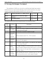
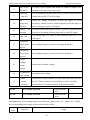
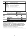
5.7 Group F6 Output Terminal................................................................................. 82
5.8 Group F7 Auxiliary function and Man-Machine Interface Function..................85
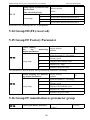
5.9 Group F8 Communication Parameter Description..............................................93
5.10 Group F9 Fault and Protection..........................................................................95
5.11 Group FA Process Control PID Function......................................................... 99
5.12 Group FB Swing Frequency........................................................................... 102
1
M420 General Flux Vector Control Inverter User Manual
5.13 Group FC MS Speed Function and Simple PLC Function............................. 104
5.14 Group FD,FE (reserved)................................................................................. 109
5.15 Group FF Factory Parameter.......................................................................... 109
Chapter6 EMC(Electromagnetic Compatibility)................................................ 110
6.1 Definition.......................................................................................................... 110
6.2 Standard Description.........................................................................................110
6.3 EMC Guide....................................................................................................... 111
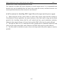
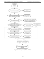
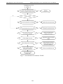
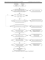
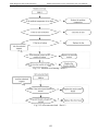
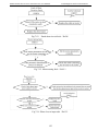
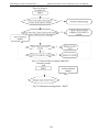
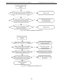
Chapter 7 Fault Diagnosis and Countermeasures..................................................114
7.1 Fault Alarm and Countermeasures....................................................................114
7.2 Common Fault and Resolution......................................................................... 126
Chapter 8 M420 Series Serial Port Communication Protocol.............................. 127
8.1 About Protocol.................................................................................................. 127
8.2 Application mode..............................................................................................127
8.3 Bus Structure.....................................................................................................127
8.4 Protocol specification........................................................................................128
8.5 Communication frame structure........................................................................128
8.6 Cyclical Redundancy Check............................................................................. 131
8.7 CMD and Status................................................................................................ 132
Chapter 9 M420 Options..........................................................................................135
9.1 DC Reactors................................................................................................135
9.2 Output circuit filters....................................................................................135
9.3 Ferrite ring reactors for reducing radio frequency noise............................136
9.4 EMC-compliant filter..................................................................................136
9.5 AC Reactor..................................................................................................136
Appendix:Function Parameter Table...................................................................... 135
2
M420 General Flux Vector Control Inverter User Manual
Preface
Preface
Thank you for purchasing M420 series Flux Vector Control Inverter.
M420 series Inverter which is a new generation of modular can flexibly satisfy customers’
individual requirements and industry demand by extension of design on the premise that meet
general purpose of the customers , representing the tendency of applying in the future inverters
industry.In meeting to the requirements of all kinds of complicated high precision transmission
with all functions of built-in universal extended interface, power speed control, torque
control ,practical process closed-loop control,simple PLC ,flexible I/O terminal, pulse frequency
given ,frequency given channel and run command channel bundled,main auxiliary given
control ,swing frequency control ,speed track ,encoder break monitoring, interior break unit ,28
species fault monitoring,more than 16 MS speed control,parameters copies ,etc, at the same
time,it provides equipment manufacturer with an all in-one solution of high integration ,on
reducing system cost and improving system reliability have a great value.
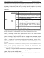
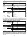
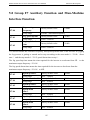
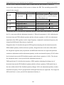
We offer two sub- modules for user as options ,that is,M420 functional module and High
performance modulation magnetic flux vector control inverter functional module ,the
modular design will represent the development of inverter in the future .There are different
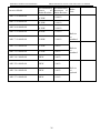
between the two modules shown in Table 1
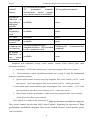
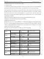
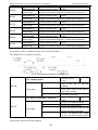
Tab.1 Difference between M420 and High performance modulation magnetic flux vector
control inverter functional modules
High performance modulation M420:General Magnetic Flux
magnetic flux vector control Vector Control Inverter
inverter
Input/Output
Internal
6×DI bidirectionalinput,2×AI,
5×DI ( bidirectional input
2×DO ( one high speed port
non-high speed ) , 2×AI ,
FM
)
,
1×AO
,
1×DO,1×AO,1×Relay
1×Relay,(expandable)I/O
Control
mode
open loop magnetic flux vector
V/F
close loop magnetic flux vector
open loop torque
close loop torque
3
open loop magnetic
vector 1
open loop magnetic
vector 2
V/F
open loop torque
flux
flux
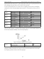
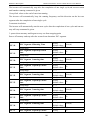
M420 General Flux Vector Control Inverter User Manual
Preface
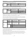
AC asynchronous motor
AC
permanent
magnetic
synchronous motor (simple
servo motor function available)
control
motor
expansion
function of
specialized
industrial
module
I/O
expansion
card
PG card
fixed-length
control
AC asynchronous motor
available
none
available
none
available
none
available
none
communicati
on function
Modbus(communication
Modbus(485
standard)Profibus DP(extended
standard)
by the expansion card)
switching
function of
two motor
parameters
available
communication
none
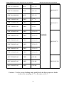
compared with traditional voltage vector control ,current vector control gains main
advantages as follow :
1、start torque:0.5Hz,180% rated torque(open loop magnetic flux vector control );
2 、 Flux-weakening control algorithm,maximum can exceed 2 times the fundamental
frequency operation of motor;
3、precise speed control accuracy:open loop magnetic flux vector control ≤±0.5%(rated
sync-speed),close loop magnetic flux vector control ≤±0.2%(rated sync-speed);
4、more stable speed control stability:open loop magnetic flux vector control
≤±0.3(rated
sync-speed,close open flux vector control≤±0.1%(rated sync-speed);
5、faster torque response performance ≤40ms (open loop magnetic flux vector control);
≤20ms (close loop flux vector control)。
This manual is a guide to the operations of High performance modulation magnetic
flux vector control inverter and M420 control module .Regarding the operation of High
performance modulation magnetic flux vector control inverter control module ,please
read it for details.
4
M420 General Flux Vector Control Inverter User Manual
Preface
This manual provides the user with precautions and instructions concerning the
prototyping ,installation,parameter setting,on-site commissioning
,fault diagnosis, routine
repair and maintenance of inverter.Please read the instruction manual carefully before the proper
use of M420 series Inverter ,and stay keeping it for the future use.The supporting equipment
customers shall distribute this manual together with equipment to the final users .
Unpacking and Inspection
Please confirm carefully when unpacking the box:
1、If the model and inverter rated values on the nameplate are the same as your order.The
box contains the equipment certificate of conformity ,user manual and warranty card
2、If the product is damaged during the transportation,please contact our company or the
supplier immediately if there is any omission or damage.
Fist time use :
The users who use the product for fit time shall read this manual carefully .For any doubt
about certain functions and performances,please contact the technical support personnel of our
company for help so as to use the product properly.
The information our company provides are subject to change without additional notice due
to the constant improvement of the inverter products .
M420 series inverter is accordance with international standards ,and some products have passed
in CE standards
IEC/EN61800-5-1:Safety Regulation on Commissionable Electric Drive System
IEC/EN61800-3:Commissional
Electric
Drive
System
,Third
Compatibility Standard and Specific Testing Method for the Products
5
Part
:Electromagnetic
Safety and precautions
M420 General Flux Vector Control Inverter User Manual
Chapter1 safety and precautions
Safety definition:
In this manual, safety precautions are divided into two types below:
Danger arising due to improper operations may cause severe hurt or even death.
Danger arising due to improper operations may cause moderate hurt or light hurt or equipment
damage.
1.1 Safety precautions
1.1.1 Before Installation:
1.
2.
Do not use the damaged inverter or inverter with missing parts. Otherwise, there may be
risk of injury.
Use the motor with Class B or above insulation. Otherwise, there may be risk of electric
shock.
1.1.2 During the Installation:
1.
Mount the inverter on incombustible surface like metal, and keep away from famal
substances. Otherwise it may cause fire.
2.
When more than two inverters are to be installed in one cabinet, due attention shall be paid
to the installation locations (refer to Chapter 3 Mechanical and Electrical Installation) to
ensure the heat sinking effect.
Do not drop the lead wire stub or screw in the inverter. Otherwise it may damage the
inverter.
3.
1.1.3 During wiring:
1.
2.
3.
4.
Operation shall be performed by the professional engineering technician. Otherwise there
will be danger of electric shock!
There shall be circuit breaker between the inverter and power supply. Otherwise, there may
be free!
Make sure the power is disconnected prior to the connection.Otherwise there will be danger
of electric shock!
The earth terminal shall be earthed reliably. Otherwise there may be danger of electric
6
M420 General Flux Vector Control Inverter User Manual
Safety and precautions
shock.
5.
6.
cannot be input power line is connected to the output of the U, V, W. Otherwise
the damage caused by frequency converter!
ensure line to meet safety standards EMC requirements and the region. The wire
diameter please refer to the manual recommended. Otherwise, an accident may occur!
7.
The brake
resistance
can not be directly connected
to the
DC
bus (+), (-) terminals. Otherwise it may cause fire!
1.1.4 Before Power-on:
1.
2.
3.
4.
Please confirm whether the power voltage class is consistent with the rated voltage of the
inverter and whether the I/O cable connecting positions are correct,and check whether the
external circuit is short circuited and whether the connecting line is from.Otherwise it may
damage the inverter.The cover must be well closed prior to the inverter power-on.
Otherwise electric shock may be caused.
The cover must be well closed prior to the inverter power-on.Otherwise electric shock may
be caused!
The inverter is free from dielectric test because this test is performed prior to the delivery.
Otherwise accident may occur!
Whether all the external fittings are connected correctly in accordance with the circuit
provided in this manual.Otherwise accident may occur!
1.1.5 Upon Power-on
1.
2.
3.
4.
5.
6.
Do not open the cover of the inverter upon power-on.Otherwise there will be danger of
electric shock!
Do not touch the inverter and its surrounding circuit with wet hand.Otherwise there will be
danger of electric shock!
Do not touch the inverter terminals(including control terminal).Otherwise there will be
danger of electric shock!
At power-on,the inverter will perform the security check of the external heavy-current
circuit automatically.Thus,at this time please do not touch the terminals U, V and W,or the
terminals of motor,otherwise there will be danger of electric shock.
If parameter identification is required,due attention shall be paid to the danger of injury
arising from the rotating motor.Otherwise accident may occur!
Do not change the factory settings at will. Otherwise it may damage the equipment!
1.1.6 During the operation:
7
Safety and precautions
1.
2.
3.
4.
5.
M420 General Flux Vector Control Inverter User Manual
Do not close to the machinery and equipment if select restart function. Otherwise,personal
injury may be caused!
Do not touch the fan or discharge resistor to sense the temperature.Otherwise,you may get
burnt!
Detection of signals during the operation shall only be conducted by qualified technician.
Otherwise, personal injury or equipment damage may be caused!
During the operation of the inverter, keep items from falling into the equipment.Otherwise,
it may damage the equipment!
Do not start and shut down the inverter by connecting and disconnecting the contactor.
Otherwise, it may damage the equipment!
1.1.7 During Repair
1. Do not repair and maintain the equipment with power connection.Otherwise there will be
danger of electric shock!
2. be sure to conduct repair and maintenance after the charge LED indictor of the inverter is
OFF. Otherwise, the residual charge on the capacitor may cause personal injury!
3. The inverter shall be repaired and maintained only by the qualified person who has received
professional training.Otherwise,it may cause personal injury or equipment damage!
1.2 Precautions
1.2.1 Motor Insulation Inspection
When the motor is used for the first time,or when the motor is reused after being kept,or
when periodical inspection is performed, it shall conduct motor insulation inspection so as to
avoid damaging the inverter because of the insulation failure of the motor windings.The motor
wires must be disconnected from the inverter during the insulation inspection.It is recommended
to use the 500V megameter, and the insulating resistance measured shall be at least 5MΩ.
1.2.2 Thermal Protection of the Motor
If the ratings of the motor does not match those of the inverter,especially when the rated
power of the inverter is higher than the rated power of the motor, the relevant motor protection
parameters in the in the inverter shall be adjusted, or thermal relay shall be mounted to protect
the motor.
1.2.3 Running with Frequency higher than Standard Frequency
This inverter can provide output frequency of 0Hz to 400Hz. If the user needs to run the
inverter with frequency of more than 50Hz, please take the resistant pressure of the mechanical
8
M420 General Flux Vector Control Inverter User Manual
Safety and precautions
devices into consideration.
1.2.4 Vibration of Mechanical Device
The inverter may encounter the mechanical resonance point at certain output
frequencies,which can be avoided by setting the skip frequency parameters in the inverter.
1.2.5 Motor Heat and Noise
Since the output voltage of inverter is PWM wave and contains certain harmonics, the
temperature rise, noise and vibration of the motor will be higher than those when it runs at
standard frequency.
1.2.6 Voltage-sensitive Device or Capacitor Improving Power Factor at the Output Side
Since the inverter output is PWM wave,if the capacitor for improving the power factor or
voltage-sensitive resistor for lightning protection is mounted at the output side,it is easy to cause
instantaneous over current in the inverter,which may damage the inverter.It is recommended that
such devices not be used.
1.2.7 Switching Devices like Contactors Used at the Input and Output terminal
If a contactor is installed between the power supply and the input terminal of the inverter,
it is not allowed to use the contactor to control the startup/stop of the inverter. If use of such
contactor is unavoidable,it shall be used with interval of at least one hour. Frequent charge and
discharge will reduce the service life of the capacitor inside the inverter.If switching devices
like contactor are installed between the output end of the inverter and the motor, it shall ensure
that the on/off operation is conducted when the inverter has no output.Otherwise the modules in
the inverter may be damaged.
1.2.8 Use under voltage rather than rated voltage
If the M420 series inverter is used outside the allowable working voltage range as
specified in this manual, it is easy to damage the devices in the inverter.
When necessary, use the corresponding step-up or step-down instruments to change
the voltage.
1.2.9 Change Three-phase Input to Two-phase Input
It is not allowed to change the M420 series three-phase inverter into two-phase
one.Otherwise, it may cause fault or damage to the inverter.
1.2.10 Lightning Impulse Protection
The series inverter has lightning over current protection device, and has certain
self-protection capacity against the lightning.In applications where lightning occurs frequently,
the user shall install additional protection devices at the front-end of the inverter.
9
Safety and precautions
M420 General Flux Vector Control Inverter User Manual
1.2.11 Altitude and Derating
In areas with altitude of more than 1,000 meters, the heat sinking effect of the inverter
may turn poorer due to rare air.Therefore, it needs to derate the inverter for use. Please contact
our company for technical consulting in case of such condition.
1.2.12 Certain Special Use
If the user needs to use the inverter with the methods other than the recommended wiring
diagram in this manual, such as shared DC bus, please consult our company.
1.2.13 Note of Inverter Disposal
The electrolytic capacitors on the main circuit and the PCB may explode when they are
burnt. Emission of toxic gas may be generated when the plastic parts are burnt.Please dispose
the inverter as industrial wastes.
1.2.14 Adaptable Motor
1) The standard adaptable motor is four-pole squirrel-cage asynchronous induction motor. If
such motor is not available, be sure to select adaptable motors in according to the rated current
of the motor.In applications where drive permanent magnetic synchronous motor is required,
please consult our company;
2) The cooling fan and the rotor shaft of the non-variable-frequency motor adopt coaxial
connection.When the rotating speed is reduced,the cooling effect will be poorer.Therefore,a
powerful exhaust fan shall be installed,or the motor shall be replaced with variable-frequency
motor to avoid the over heat of the motor.
3) Since the inverter has built-in standard parameters of the adaptable motors,it is necessary to
perform motor parameter identification or modify the default values so as to comply with the
actual values as much as possible,or it may affect the running effect and protection performance;
4) The short circuit of the cable or motor may cause alarm or explosion of the inverter.Therefore,
please conduct insulation and short circuit test on the newly installed motor and cable.Such test
shall also be conducted during routine maintenance. Please note that the inverter and the test
part shall be completely disconnected during the test.
10
M420 General Flux Vector Control Inverter User Manual
Mechanical and Electrical Installation
Chapter 2 Product Information
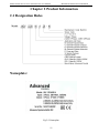
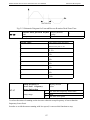
2.1 Designation Rules
Nameplate:
Fig.2-2 Nameplate
11
Mechanical and Electrical Installation
M420 General Flux Vector Control Inverter User Manual
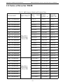
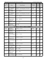
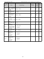
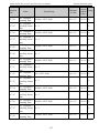
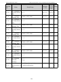
2.2 Series of Inverter M420
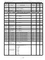
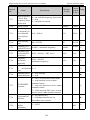
Tab.2-1 M420 Inverter Model and Technical Data
Input current
(A)
Output
Adaptable
current(A) Motor(kW)
ADV 1.50 M420-M
5.0/3.4
3.8/2.1
1.5/0.75
ADV 2.20 M420-M
5.8/5.0
5.1/3.8
2.2/1.5
ADV 4.00 M420-M
10.5/5.8
9.0/5.1
4.0/2.2
ADV 5.50 M420-M
14.6/10.5
13.0/9.0
5.5/4.0
ADV 7.50 M420-M
20.5/14.6
17.0/13.0
7.5/5.5
ADV 11.0 M420-M
26.0/22.0
25.0/20.0
11.0/9.0
35.0/26.0
32.0/25.0
15.0/11.0
38.5/35.0
37.0/32.0
18.5/15.0
46.5/38.5
45.0/37.0
22.0/18.5
ADV 30.0 M420-M
62.0/46.5
60.0/45.0
30.0/22.0
ADV 37.0 M420-M
76.0/62.0
75.0/60.0
37.0/30.0
ADV 45.0 M420-M
92.0/76.0
90.0/75.0
45.0/37.0
ADV 55.0 M420-M
113.0/92.0
110.0/90.0
55.0/45.0
ADV 75.0 M420-M
157.0/113.0
152.0/110.0
75.0/55.0
ADV 90.0 M420-M
180.0/157.0
176.0/152.0
93.0/75.0
ADV 110 M420-M
214.0/180.0
210.0/176.0
110.0/93.0
ADV 132 M420-M
256.0/214.0
253.0/210.0
132.0/110.0
ADV 160 M420-M
307.0/256.0
304.0/253.0
160.0/132.0
345.0/307.0
340.0/304.0
185.0/160.0
385.0/345.0
380.0/340.0
200.0/185.0
ADV 220 M420-M
430.0/385.0
426.0/380.0
220.0/200.0
ADV 250 M420-M
468.0/430.0
465.0/426.0
250.0/220.0
ADV 280 M420-M
525.0/468.0
520.0/465.0
280.0/250.0
Inverter model
ADV 15.0 M420-M
ADV 18.5 M420-M
ADV 22.0 M420-M
ADV 185 M420-M
ADV 200 M420-M
Input voltage(V)
Three Phase
380V Range:
-15% to 20%
Three Phase
380V Range:
-15% to 20%
12
M420 General Flux Vector Control Inverter User Manual
Mechanical and Electrical Installation
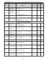
ADV 315 M420-M
590.0/525.0
585.0/520.0
315.0/280.0
ADV 355 M420-M
665.0/590.0
650.0/585.0
355.0/315.0
ADV 400 M420-M
785.0/665.0
725.0/650.0
400.0/355.0
ADV 450 M420-M
883.0/785.0
820.0/725.0
450.0/400.0
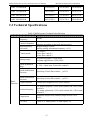
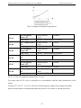
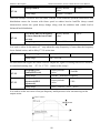
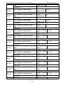
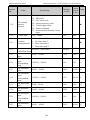
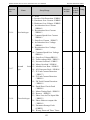
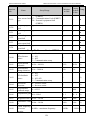
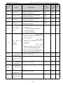
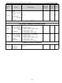
2.3 Technical Specifications
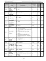
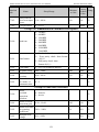
Tab.2-2 M420 Inverter Technical Specifications
Specifications
Item
Maximum
frequency
Carrier Frequency
Input frequency
resolution
400Hz
1k to 15kHz; the carrier frequency will be automatically
adjusted according to the load characteristics.
Digital setting: 0.01Hz
Analog setting: maximum frequency ×0.1%
Control mode
V/F control
Vector flux control 1
Vector flux control 2
Startup torque
for general purpose: 0.5Hz/180%
for pump application: 0.5Hz/120%
Speed adjustment
range
1:200(Open loop Vector flux control)
Speed stabilization
precision
Open loop Vector flux control:≤±0.5%
Speed stabilization
precision
Open loop Vector flux control:≤±0.3%
Basic
function Torque response
≤40ms(Open magnetic flux vector control)
Overload capacity
For general purpose: 150% rated current 60s; 180% rated
current 3s
For pump application: 130% rated current 60s; 150% rated
current 3s
Torque hoist
Automatic torque hoist; manual torque hoist 0.1% to
30.0%
V/F curve
Linear V/F, Multi-point V/F, and Square V/F
13
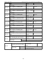
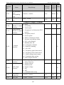
Mechanical and Electrical Installation
Item
M420 General Flux Vector Control Inverter User Manual
Specifications
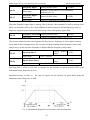
Speed-up and
Speed-down curve
Straight line or S curve speed-up and speed-down
mode;Two kinds of speed-up and speed-down
time;Speed-up and speed-down time ranges between 0.0s
to 3000.0min.
DC brake
DC brake frequency:0.00Hz to maximum frequency; brake
time:0.0s to 36.0s,and brake current value: 0.0% to
100.0%.
Jog control
Jog frequency range:0.00Hz to 50.00Hz;jog
speed-up/speed-down time: 0.0s to 3000.0s.
Simple PLC and MS It can realize a maximum of 16 segments speed running
speed running
via the built-in PLC or control terminal.
Built-in PID
It is easy to realize process-controlled close loop control
system.
(AVR)Auto
voltage regulation
It can keep constant output voltage automatically in case
of change of mains voltage.
Torque
and control
"Shovel" characteristics, the runtime automatic torque
limit, prevent frequent over-current trip; closed loop vector
model can realize the torque control
limit
Peripherals
self-detection upon
power-on
It can conduct safety detections on the peripherals upon
power-on, including earth and short circuit detections.
Shared DC bus
function
It can realize the function that multiple inverters share the
DC bus.
JOG key
Programmable key: Select the command channel
switching/forward and reverse rotations/jog operation.
IndividuaTextile swing
lized
frequency control
function
Multiple triangular-wave frequency control function.
CBC Function
Built-CBC algorithm to reduce the probability of
over-current converter reported to improve the whole
anti-jamming capacity.
Timing control
Timing control function: Setting time range between 0h
to 65535h.
Keyboard extension Customers can use standard cable extension the
line standard
keyboard
Run
Running command
channel
Three types of channels:operation panel reference,control
terminal reference and serial communication port
reference. These channels can be switched in various
modes.
14
M420 General Flux Vector Control Inverter User Manual
Item
Mechanical and Electrical Installation
Specifications
Frequency source
There are totally ten types of frequency sources, such as
digital reference, analog voltage reference, analog current
reference, MS speed, PLC, PID, and serial port reference.
There are ten types of auxiliary frequency sources.It can
Auxiliary frequency
implement micro tuning and synthesis of auxiliary
source
frequency.
Input terminal
There are five digital input terminals.It can be compatible
with active PNP or NPN input mode.
There are two analog input terminals,one of which can be
used only as voltage input,while the other can be used as
voltage or current input.
(It can expand one voltage
input terminal)
Output terminal
One digital output terminal
Two relays output terminal
One analog output terminal,with optional 0/4mA to 20mA
or 0/2V to 10V. It can realize the output of such physical
parameters as setting frequency and output frequency.
LED display
The machine has the LED keyboard,and realize parameter
settings,status monitoring function.
Display LCD display
and
Keyboard Parameter Copy
Operation
Optional, / English prompts content
Keyboard can be copied using the parameters to achieve
the rapid replication parameter.
and The realization of key part or all of the lock, define the
Key lock
function selection
scope of the keys, to prevent mis-operation
15
Mechanical and Electrical Installation
Others
M420 General Flux Vector Control Inverter User Manual
Protection
function
It can implement power-on motor short-circuit detection,
input/output phase loss protection, over current protection,
over voltage protection, under voltage protection,
overheating protection and overload protection.
Accessories
LCD Operation Panel、Brake Unit.
Using place
Indoor, and be free from direct sunlight, dust, corrosive
gas, combustible gas, oil smoke, vapor, drip or salt.
Altitude
1000m, derated when above 1000m
Ambient
environm temperature
ent
Humidity
Vibration
-10 ℃ Celsius to +40 ℃ Celsius (Derated when used in
the ambient temperature of 40 ℃ Celsius to 50 ℃
Celsius)
Less than 95%RH, without condensing
Less than 5.9 m/s2(0.6g)
Storage temperature -20 Celsius to +60 Celsius
Class of pollution
2
Product
implementation
IEC61800-5-1:2007
Products of safety standards
Standard
Implementation of
IEC61800-5-1:2007
EMC standard
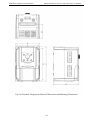
2.4 Physical Appearance and Dimensions of Mounting
Hole
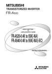
2.4.1 Product Appearance
16
M420 General Flux Vector Control Inverter User Manual
Mechanical and Electrical Installation
Fig.2-3 Physical Appearance of Inverter
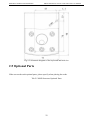
2.4.2 Mounting Hole Dimensions
17
Mechanical and Electrical Installation
M420 General Flux Vector Control Inverter User Manual
Fig.2-4 Schematic Diagram for Physical Dimensions and Mounting Dimensions
18
M420 General Flux Vector Control Inverter User Manual
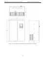
Mechanical and Electrical Installation
Figure 2-5 sheet metal converter dimension and installation size diagram
19
Mechanical and Electrical Installation
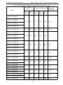
M420 General Flux Vector Control Inverter User Manual
Tab. 2-3 Mounting Hole Dimensions of M420 Series Inverter(mm)
Diameter of
Mounting
Mounting
Physical Dimension
Hole
Hole (mm)
Model
B
D
A
H
W
(mm
(mm
(mm)
(mm)
(mm)
)
)
ADV 1.50 M420-M
ADV 2.20 M420-M
135
207
223
148
159
φ5.4
150
226
238
162
165
φ5.4
160
326
340
222
194
φ7
200
460
485
260
230
φ10
220
545
565
330
252
φ10
300
563
588
380
266
φ12
320
635
660
460
290
φ12
340
845
875
475
305
φ12
380
1066
1100
520
355
φ12
370
855
890
520
355
φ12
500
1320
1360
700
380
φ14
ADV 4.00 M420-M
ADV 5.50 M420-M
ADV 7.50 M420-M
ADV 11.0 M420-M
ADV 15.0 M420-M
ADV 18.5 M420-M
ADV 22.0 M420-M
ADV 30.0 M420-M
ADV 37.0 M420-M
ADV 45.0 M420-M
ADV 55.0 M420-M
ADV 75.0 M420-M
ADV 90.0 M420-M
ADV 110 M420-M
ADV 132 M420-M
ADV 160 M420-M
ADV 185 M420-M
ADV 200 M420-M
ADV 185 M420-M(cabinet)
ADV 200 M420-M(cabinet)
ADV 220 M420-M
20
M420 General Flux Vector Control Inverter User Manual
Mechanical and Electrical Installation
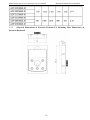
2.4.2 ) Physical Dimensions of External Keyboard 2) Mounting Hole Dimensions of
External Keyboard
21
Mechanical and Electrical Installation
M420 General Flux Vector Control Inverter User Manual
Fig.2-5 Schematic diagram of the keyboard and hole size
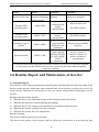
2.5 Optional Parts
If the user needs such optional parts, please specify when placing the order.
Tab.2-5 M420 Inverters Optional Parts
22
M420 General Flux Vector Control Inverter User Manual
Name
Built-in brake unit
External LED
operating panel
Model
The letter “ B”
attached behind the
product model
M420-LED
Mechanical and Electrical Installation
Function
Remarks
Braking
Built-in as standard
External LED
display
and keyboard
M series universal
The RJ45 interface
External LCD
display
The RJ45 interface
and keyboard
The
Parameter copy k
copy function
M series universal RJ45
M420 -LED2
eyboard
interface
keyboard with
parameters
Standard 8 core
cable, can and
For the 1 meters, 3
M420-LED, M4
meters, 5 meters, 10
Extension cable
M420 -CAB
20-LCD, M420meters, 4 kinds of
LED2
specifications
connection
If you need other function module extensions (such as: I/O card, PG card, EPS card and
so on), please use theCM580 series inverter, specifying the order function module
card when ordering.
External LCD
operating panel
M420 -LCD
2.6 Routine Repair and Maintenance of inverter
2.7.1 Routine Repair
The influence of the ambient temperature,humidity,dust and vibration will cause the aging of the
devices in the inverter, which may cause potential fault of the inverter or reduce the service life
of the inverter.Therefore,it is necessary to carry out routine and periodical maintenance on the
inverter.
Routine inspection Items include:
1) Whether there is any abnormal change in the running sound of the motor;
2) Whether the motor has vibration during the running;
3) Whether there is any change to the installation environment of the inverter;
4) Whether the inverter cooling fan works normally;
5) Whether the inverter has over temperature;
Routine cleaning:
The inverter shall be kept clean all the time.
The dust on the surface of the inverter shall be effectively removed,so as to prevent the dust
23
Mechanical and Electrical Installation
M420 General Flux Vector Control Inverter User Manual
entering the inverter.Especially the metal dust is not allowed.
The oil stain on the inverter cooling fan shall be effectively removed.
2.7.2 Periodic Inspection
Please perform periodic inspection on the places where the inspection is a difficult thing.
Periodic inspection Items include:
1) Check and clean the air duct periodically;
2) Check if the screws are loosened;
3) Check if the inverter is corroded;
4) Check if the wire connector has arc signs;
5) Main circuit insulation test;
Remainder: When using the megameter (DC 500V megameter recommended) to measure the
insulating resistance,the main circuit shall be disconnected with the inverter.Do not use the
insulating resistance meter to control the insulation of the circuit. It is not necessary to conduct
the high voltage test (which has been completed upon delivery).
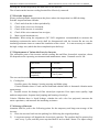
2.7.3 Replacement of Vulnerable Parts for Inverter
The vulnerable parts of the inverter include cooling fan and filter electrolytic capacitor, whose
life depends on the operating environment and maintenance status. Common service life:
Part name
Life time
Fan
2 to 3 years
Electrolytic
4 to 5 years
capacitor
The user can determine the term for replacement according to the running time.
1) Cooling fan
Possible causes for damage: bearing wearing and blade aging.
Criteria:Whether there is crack on the blade and whether there is abnormal vibration noise
upon startup.
2) Possible causes for damage of filter electrolytic capacitor: Poor input source quality, high
ambient temperature, frequent load jumping and burning electrolyte.
Criteria: Whether there is liquid leakage, whether the safe valve has projected, measure the
static capacitance, and measure the insulating resistance.
2.7.4 Storage of Inverter
Attention shall be paid to the following points for the temporary and long-term storage of the
inverter:
1) Place the inverter back into the packing box following the original package;
2)
Long-term storage will degrade the electrolytic capacitor. The product shall be powered up
once every 2 years, and the power-up time shall be no less than 5 hours. The input voltage
24
M420 General Flux Vector Control Inverter User Manual
Mechanical and Electrical Installation
shall be increased slowly to the rated value with the regulator.
2.7 Instructions on Warranty of Inverter
Free warranty only applies to the inverter itself.
1 、 Our company will provide 18-month warranty (starting from the leave-factory date as
indicated on the barcode) for the fault or damage under normal use conditions.If the
equipment has been used for over 18 months, reasonable repair expenses will be charged.
2、Reasonable repair expenses will be charged for the following situations within 18 months:
1) The equipment is damaged because the user fails to comply with the requirements of the
user’s manual;
2) Damage caused by fire, flood and abnormal voltage;
3) Damage caused when the inverter is used for abnormal function.
The service expenses will be calculated according to the standard of the manufacturer.If there is
any agreement, the agreement shall prevail.
2.8 Guide to Model Selection
When selecting inverter, firstly make clear the details regarding the technical requirements for
variable frequency speed adjustment of the system, applications of inverter and load
characteristics and take into overall consideration the adaptable motor, output voltage, rated
output and other factors, and then select the model meeting your requirements and determine the
running mode.
The basic principle is that the rated load current of the motor cannot exceed the rated current of
the inverter. Generally, the model is selected in accordance with the capacity of the supporting
motor as specified in the user’s manual, with attention to the comparison of rated currents
between
the motor and the inverter. The overload capacity of the inverter makes sense only for the
startup and brake processes. If instantaneous overload occurs in the running process, the load
speed will vary. If there are higher requirements for the speed precision, please consider a larger
one.
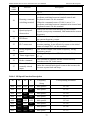
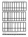
2.9 Guide to Selection of Brake Components
Tab.2-5 Selection of Inverter Brake Components
25
Mechanical and Electrical Installation
M420 General Flux Vector Control Inverter User Manual
Recommended
Power
of
Brake Resistor
Recommended
Resistance of
Brake Resistor
0.3KW
≥300Ω
0.3KW
≥300Ω
0.3KW
≥300Ω
ADV 5.50 M420-M
0.6KW
≥130Ω
ADV 7.50 M420-M
1.0KW
≥100Ω
ADV 11.0 M420-M
1.5KW
≥60Ω
ADV 15.0 M420-M
1.5KW
≥60Ω
ADV 18.5 M420-M
2KW
≥40Ω
ADV 22.0 M420-M
2KW
≥40Ω
ADV 30.0 M420-M
2KW
≥40Ω
ADV 37.0 M420-M
4KW
≥24Ω
Inverter Model
ADV 1.50 M420-M
ADV 2.20 M420-M
ADV 4.00 M420-M
26
Brake
Unit
Built-in
as
standard
Built-in
as
standard
Built-in
as
optional
M420 General Flux Vector Control Inverter User Manual
ADV 45.0 M420-M
6KW
≥13.6Ω
ADV 75.0 M420-M
6KW
≥13.6Ω
ADV 90.0 M420-M
6KW
≥13.6Ω
ADV 110 M420-M
12KW
≥6.8Ω
ADV 132 M420-M
12KW
≥6.8Ω
ADV 160 M420-M
12KW
≥6.8Ω
ADV 185 M420-M
12KW
≥2*6.8Ω
ADV 200 M420-M
12KW
≥2*6.8Ω
ADV 220 M420-M
12KW
≥2*6.8Ω
ADV 250 M420-M
12KW
≥2*6.8Ω
ADV 280 M420-M
12KW
≥2*6.8Ω
ADV 315 M420-M
12KW
≥2*6.8Ω
ADV 355 M420-M
12KW
≥2*6.8Ω
ADV 400 M420-M
12KW
≥2*6.8Ω
ADV 450 M420-M
12KW
≥2*6.8Ω
Mechanical and Electrical Installation
BR530-4T07
5
BR530-4T13
2
Externally
connected
BR530-4T31
5
BR530-4T450
Caution: ×2 refers to two braking units paralleled with their respective brake
resistor; the meaning of ×3 is the same with ×2.
27
Mechanical and Electrical Installation
M420 General Flux Vector Control Inverter User Manual
Chapter 3 Mechanical and Electrical Installation
3.1 Mechanical Installation
3.1.1 Installation environment:
1) Ambient temperature: The ambient temperature exerts great influences on the service life of
the inverter and is not allowed to exceed the allowable temperature range (-10 ℃ Celsius to
50 ℃ Celsius).
2) The inverter shall be mounted on the surface of incombustible articles, with sufficient spaces
nearby for heat sinking. The inverter is easy to generate large amount of heat during the
operation. The inverter shall be mounted vertically on the base with screws.
3) The inverter shall be mounted in the place without vibration or with vibration of less than
0.6G, and shall be kept away from such equipment as punching machine.
4) The inverter shall be mounted in locations free from direct sunlight,high humidity and
condensate.
5) The inverter shall be mounted in locations free from corrosive gas,explosive gas or
combustible gas.
6) The inverter shall be mounted in locations free from oil dirt, dust, and metal powder.
28
M420 General Flux Vector Control Inverter User Manual
Mechanical and Electrical Installation
Fig.3-1 M420 Inverter Installation Diagram
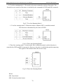
3.1.2 Heat sinking shall be taken into account during the installation.Attention shall be
paid to the following items:
1) Install the inverter vertically so that the heat may be expelled from the top.However, the
equipment cannot be installed upside down. If there are multiple inverters in the cabinet, parallel
installation is better. In the applications where up-down installation is required, please install the
thermal insulating guide plate referring to the schematic diagrams for standalone installation and
up-down installation.
2) The mounting space shall be as indicated as the above diagrams, so as to ensure the heat
sinking space of the inverter. However, the heat sinking of other devices in the cabinet shall also
be considered.
3) The installation bracket must be made of flame retardant materials.
4) In the applications where there are metal powders, it is recommended to install the radiator
outside the cabinet.In this case,the space inside the sealed cabinet shall be large as much as
possible.
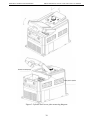
3.1.3 Under cover remove and installation
29
Mechanical and Electrical Installation
M420 General Flux Vector Control Inverter User Manual
Figure 3-2 plastic shell cover plate removing diagram
30
M420 General Flux Vector Control Inverter User Manual
Mechanical and Electrical Installation
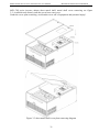
9kW CM series inverter adopts sheet metal shell, metal shell cover removing see figure
3-3. Available tools directly turn the screw loose can cover.
Under the cover plate removing, avoid under cover off of equipment and personal injury!
Figure 3-3 sheet metal shell cover plate removing diagram
31
Mechanical and Electrical Installation
M420 General Flux Vector Control Inverter User Manual
3.2 Electrical installation
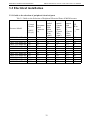
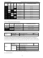
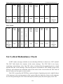
3.2.1 Guide to the selection of peripheral electrical parts
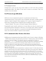
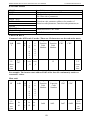
Tab.3-1 Guide to the Selection of Peripheral Electrical Parts of M420 Inverter
Recomm Recomm Reco
ended
ended
mmen
Circuit
PE
Output
ded
Recomme Input
Breake
nded
Side
Side
Contro Wire
r
Inverter Model
( mm
Contactor Main
Main
l
(MCC
(A)
Circuit
Circuit
Circuit ²)
B) (A)
Wire
Wire
Wire
(mm²)
(mm²)
(mm²)
ADV 1.50 M420-M 10
10
2.5
2.5
1.5
2.5
ADV 2.20 M420-M 16
10
2.5
2.5
1.5
2.5
ADV 4.00 M420-M 16
10
2.5
2.5
1.5
2.5
ADV 5.50 M420-M 25
16
4
4
1.5
4
ADV 7.50 M420-M 32
25
4
4
1.5
4
ADV 11.0 M420-M 40
32
6
6
1.5
6
ADV 15.0 M420-M 50
40
6
6
1.5
6
ADV 18.5 M420-M 50
40
6
6
1.5
6
ADV 22.0 M420-M 63
63
10
10
1.5
10
ADV 30.0 M420-M 80
63
16
16
1.5
16
ADV 37.0 M420-M 100
100
16
16
1.5
16
ADV 45.0 M420-M 125
100
25
25
1.5
25
32
M420 General Flux Vector Control Inverter User Manual
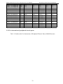
ADV 55.0 M420-M
ADV 75.0 M420-M
ADV 90.0 M420-M
ADV 110 M420-M
ADV 132 M420-M
ADV 160 M420-M
ADV 185 M420-M
ADV 200 M420-M
ADV 220 M420-M
ADV 250 M420-M
ADV 280 M420-M
ADV 315 M420-M
ADV 355 M420-M
ADV 400 M420-M
ADV 450 M420-M
160
180
200
225
250
315
350
400
500
630
630
800
800
1000
1000
125
125
160
160
350
400
400
600
600
600
630
800
800
1000
1000
Mechanical and Electrical Installation
25
35
50
70
120
150
185
150*2
150*2
185*2
185*2
185*2
150*3
150*4
150*4
25
35
50
70
120
150
185
150*2
150*2
185*2
185*2
185*2
150*3
150*4
150*4
1.5
1.5
1.5
1.5
1.5
1.5
1.5
1.5
1.5
1.5
1.5
1.5
1.5
1.5
1.5
25
25
25
25
25
25
25
25
35
35
35
35
35
35
35
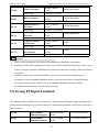
3.2.2 Use instruction of peripheral electric parts:
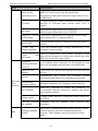
Tab.3-1 Guide to the Use Instruction of Peripheral Electric Parts of M420 Inverter
33
Mechanical and Electrical Installation
Part Name
Circuit
breaker
Contactor
Installation
Location
The front-end
of the input
circuit
Between the
circuit breaker
and the
inverter
input side
AC input
reactor
Input side of
the inverter
EMC input
filter
Input side of
the inverter
AC output
reactor
Between the
inverter output
side and the
motor, close to
the inverter
M420 General Flux Vector Control Inverter User Manual
Function Description
Disconnect the power supply in case of
downstream equipment is over current.
Power-on and power-off of the inverter.Frequent
power-on/power-off operation on the inverter shall
be avoided.
1.Improve the power factor of the input side.
2.Eliminate the high order harmonics of the input
side effectively, and prevent other equipment from
damaging due to voltage waveform deformation.
3.Eliminate the input current unbalance due to the
unbalance among the phase of input.
1)
Reduce the external conduction and radiation
interference of the inverter;
2)
Reduce the conduction interference flowing
from the power end to the inverter, thus improving
the anti-interference capacity of the inverter.
The inverter output side generally has higher
harmonic.When the motor is far from the inverter,
since there are many capacitors in the circuit,
certain harmonics will cause resonance in the
circuit and bring in the following results:
1) Degrade the motor insulation performance and
damage the motor for the long run.
2) Generate large leakage current and cause
frequent inverter protection action.
3) In general, if the distance between the inverter
and the motor exceeds 100 meters, output AC
reactor shall be installed.
34
M420 General Flux Vector Control Inverter User Manual
Mechanical and Electrical Installation
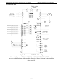
3.2.3 Wiring mode
Fig3-4.Inverters of 37KW follow Fig
Note: this figure for ADV 1.50 M420-M ~ ADV 37 M420-M(22 ~ 37KW series
inverter braking unit part of the matching function, if there is demand, when ordering
please specify)
35
Mechanical and Electrical Installation
M420 General Flux Vector Control Inverter User Manual
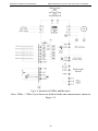
Fig.3-5 Inverters of 45Kw and the more
Note: 22Kw ~ 37Kw if you choose no built-in brake unit connection as shown in
Figure 3-5
36
M420 General Flux Vector Control Inverter User Manual
Mechanical and Electrical Installation
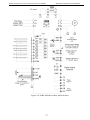
Figure 3-6 90Kw and above three phase inverter
37
Mechanical and Electrical Installation
M420 General Flux Vector Control Inverter User Manual
3.2.4 Main Circuit Terminals and Wiring
1. Make sure that the wiring operation shall be carried out only when the power supply switch
is in OFF position, or there may be risk of electric shock..
2. Only the professional technicians who have received training can perform wiring, or it may
cause injuries to the equipment and human body.
3. It shall be grounded reliably, or there may be risk of electric shock or fire accident.
1. Make sure that the input power supply and the rated value of the inverter shall be consistent,
or it may damage the inverter.
2. Make sure that the motor is compatible with the inverter,or the motor may be damaged or
inverter protection may be caused.
3. Do not connect the power supply to the U, V, W terminals, or it may damage the inverter.
4. Do not connect the brake resistor to the DC bus terminals (+) and (-) directly, or there may
be fire accident.
3.2.4.1 Description of main circuit terminals of single-phase inverter:
Terminals
L1、L2
(+)、(-)
(+)、PB
U、V、W
Name
Single-phase power
input
terminal
Negative and
positive
terminals of DC
bus
Connecting terminal
of
braking resistor
Output terminal of
inverter
Grounding terminal
Description
Connect to the AC single-phase 220V
power supply
Shared DC bus input point
Connect to the braking resistor
Connect to the three-phase motor
Grounding terminal
3.2.4.2 Description of main circuit terminals of three-phase inverter:
The three-phase 11kW main circuit terminal
identification
38
M420 General Flux Vector Control Inverter User Manual
Mechanical and Electrical Installation
Three-phase 15 ~ 18.5kW main circuit terminal identification
Three-phase 22 ~ 75kW main circuit terminal identification(safety grounding terminals in the
main circuit is a prominent position)
Three-phase 75 ~ 93kW main circuit terminal identification(safety grounding terminals in the
main circuit is a prominent position)
Three-phase 132 ~ 160kW main circuit terminal identification
Three-phase 185 ~ 315kW main circuit terminal identification(160KW above the built-in DC
reactor)
39
Mechanical and Electrical Installation
M420 General Flux Vector Control Inverter User Manual
Three-phase 350 ~ 450kW main circuit terminal identification
Terminals
R、S、T
(+)、(-)
(+)、PB
U、V、W
Name
Description
Three-phase power input
terminal
Negative and positive
terminals of DC bus
Connecting terminal for
brake resistor.
Connect to the AC three-phase 380V
power supply
Shared DC bus input point (Connect to
the external brake unit above 45KW)
Connection points for the brake unit of
of below 45KW
Output terminal of inverter
Connect to three-phase motor
Grounding terminal
Grounding terminal
3.2.4.3 Wiring Precautions
a) Input power supply terminals L1, L2, R, S or T:
There is no sequence requirement for the wiring at the Input side of the inverter.
b) DC bus (+) and (-) terminals:
The DC bus (+) and (-) terminals still have residual voltage at the time of power-off. Do not
touch the equipment until the charge LED is OFF and the voltage measured with multimeter is
less than 36V.
When selecting external brake components for the inverter of above 37kW,note that the
connecting polarity must be correct, or the inverter may be damaged and even fire accident may
occur.
The wire length of the brake unit shall not be longer than 10 meters.Twisted wires or pair wires
shall be used and connected in parallel.
Do not connect the braking resistor directly to the DC bus,otherwise, the inverter may be
damaged, and fire may be caused.
c) Connecting terminals (+) and PB of brake resistor:
The connecting terminals of the brake resistor are enabled only for the inverter of below ADV
45.0 M420-M with built-in brake unit.
40
M420 General Flux Vector Control Inverter User Manual
Mechanical and Electrical Installation
The recommended wiring distance for the brake resistor shall be less than 5m.Otherwise, the
inverter may be damaged.
Connecting terminals P and (+) of external reactor:
When assembling the inverter of above 90kw with external reactor, it needs to remove the
connector between terminals of P and (+) and connect the reactor between them instead.
d) Inverter output sides U, V and W:
The inverter output side cannot connect to the capacitor or surge absorber, otherwise, the
frequent inverter protection may be caus ed, or the inverter may be damaged.
If the wire between the motor and the inverter is too long, electrical resonance may be caused
due to the influence of the distributed capacitance, thus damaging the motor insulation or
produce large leakage current to trigger inverter over current protection. When the length of the
motor cable is longer than 100 meters, AC output reactor shall be installed.
e) Grounding terminal
:
The terminal must be grounded reliably, and the resistance of the ground wire must be less
than 0.1Ω. Otherwise, fault may be caused, or the inverter may be damaged.
Do not share the grounding terminal
and terminal N of zero line of the power supply.
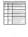
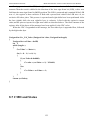
3.2.5 Control Terminals and Wiring
3.2.5.1 The terminals of the control circuit are arranged as shown in the following
diagram:
Three phase 380V 37KW control terminal
diagram
hree phase 380V 45KW above control terminal diagram
T
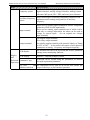
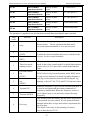
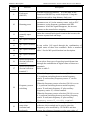
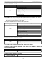
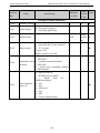
3.2.5.2 Function Description of Control Terminal
Tab.3-3 Function Description of M420 Inverter Control Terminal
Type
Power
supply
Terminal
+10V-GN
D
Terminal
Name
Function Description
External
terminal of 10V
power supply
Provide +10V power supply for external
units, with maximum output current of
10mA.
It is generally used as the operating power
supply for the external potentiometer.
The potentiometer resistance range is 1kΩ to
5kΩ.
41
Mechanical and Electrical Installation
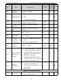
Type
Terminal
Terminal
Name
24V-COM
External
terminal of 24V
power supply
AI1-GND
Analog input
terminal 1
Analog
input
Digital
Input
AI2-GND
Analog input
terminal 2
DI1-COM
Digital Input 1
DI2-COM
Digital Input 2
DI3-COM
Digital Input 3
DI4-COM
Digital Input 4
DI5-COM
Digital Input 5
DI6-COM
Digital Input 6
DI7-COM
Digital Input 7
AO1-GND
Analog Output 1
AO2-GND
Analog Output 2
Analog
output
Digital
Output
Y1-CME
Digital output 1
M420 General Flux Vector Control Inverter User Manual
Function Description
Provide +24V power supply for external
units. It is generally used as the operating
power supply for digital input/output terminal
and the external sensor.
Maximum output current: 200mA
1、Input voltage range: DC 0V to 10V (can be
customized as non-standard -10VDC to
+10VDC)
2、Input impedance: 20kΩ
1、Input voltage range: DC 0V to 10V (can be
customized as non-standard -10VDC to
+10VDC)/0mA to 20mA, the selection of
which
depends on Key Cn3 on the control panel.
2 、 Input impedance: 20kΩ at the time of
voltage input;500Ω at the time of current
input.
1, optical coupling isolation, compatible
with bipolar input,through the DI dial
switch, the factory for NPN mode
2,Input impedance: 3.3k
3, level input voltage range: 9 ~ 30V
(DI6
DI7
terminal function
only
for three-phase 380V 45KW above
The voltage or current output is determined
by Key Cn3 on the control panel.
Output voltage range: 0V to 10V
Output current range: 0mA to 20mA
(AO2 terminal function only for three-phase
380V45KW above)
Optical coupling isolation,dual polarity open
collector output
Output voltage range: 0V to 24V
Output current range: 0mA to 50mA
42
M420 General Flux Vector Control Inverter User Manual
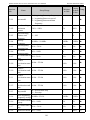
Type
Commu
nication
interface
Terminal
485+ -485-
Mechanical and Electrical Installation
Terminal
Name
Function Description
The Modbus
communication
interface
The Modbus communication interface, can
dial switch CN4 to choose
whether or not to require communication
matching resistor. For a
Profibus communication function, select the
CM580 series inverter, and chooses the
Profibus DP card.
43
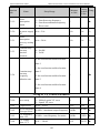
Mechanical and Electrical Installation
T/A-T/B
Relay
output
T/A-T/C
RA-RB
Relay
output 2
Keyboar
d extens
ion inte
rface
RA-RC
CN6
M420 General Flux Vector Control Inverter User Manual
Normally
closed terminal
Normally open
terminal
The normally
closed terminal
Normally
open terminal
External
keyboard interfa
ce
Contact driving capacity:
AC250V,3A,COSφ=0.4
DC 30V,1A
Contact driving ability:
AC250V,3A,COSφ=0.4。
DC30V,1A
keyboard
External keyboard,
interface parameter copy, remove the biaxial
crystal head,
you can use
standard network extension.
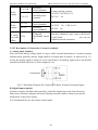
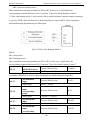
3.2.5.3 Description of Connection of control terminals:
A. Analog input terminal:
Since the weak analog voltage signal is easy to suffer external interferences, it needs to employ
shielded cable generally and the length shall be no longer than 20 meters, as shown in Fig. 3-5.
In case the analog signal is subject to severe interference, and analog signal source side shall be
installed with filter capacitor or ferrite magnetic core.
Fig.3-7 Schematic Diagram for Connection of Input Terminal of Analog Signal
B. Digital input terminal:
It needs to employ shielded cable generally, with cable length of no more than 20 meters.
When active driving is adopted, necessary filtering measures shall be taken to prevent the
interference to the power supply.
It is recommended to use the contact control mode.
44
M420 General Flux Vector Control Inverter User Manual
Mechanical and Electrical Installation
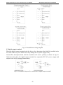
Fig 3-8 Four different wiring diagram
C. Digital output terminal:
When the digital output terminal needs the drive relay, absorption diode shall be installed at the
two sides of the relay coil. Otherwise it may damage DC 24 power supply easily.
Caution:The absorption diode shall be installed with correct polarity,as shown in Fig.3-9.
Otherwise,when there the digital output terminal has output,the DC 24V power supply and
output circuit will be damaged immediately.
Fig.3-9 Schematic diagram for connection of digital output terminal
45
Operation and Display
M420 General Flux Vector Control Inverter User Manual
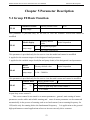
Chapter 4 Operation and Display
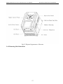
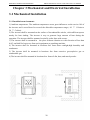
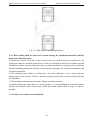
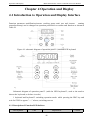
4.1 Introduction to Operation and Display Interface
Function parameter modification,inverter working status mini tore and inverter
running
control(start/stop) can be changed on operation panel.Refer to outline and function as shown in
Table 4-1
Figure 4-1 schematic diagram of operation panel 1 (standard LED keyboard
1)
Schematic diagram of operation panel 2 (with the LED keyboard 2, such as the need to
choose the keyboard, to declare in order)
1 keyboard and keyboard 2 switching operation mode: while pressing the PRG key and
wait for STOP to appear "----" release, switching success
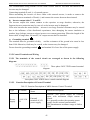
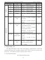
4.1.1 Description of Function LED Indictor
LED Symbol
Unit
Implication
46
Colour
M420 General Flux Vector Control Inverter User Manual
LED Symbol
Unit
Operation and Display
Implication
Colour
Unit LED
LED on——indicates frequency
Green
Current Unit
LED on——indicates current
Green
V
Voltage Unit
LED on——indicates voltage
Green
RPM
Speed Unit
LED on ——indicates speed
Green
%
Percent
LED on——indicates percentage
Green
Hz
Freq.Unit
A
values
RUN
running status
LED
LED on——in status of running
Green
for inverter
Light off——in status of stop for
inverter
L/D/C
control mode
LED
LED off——in status of keyboard
Red
control mode for inverter
LED on——in status of terminal
Function LED
control mode for inverter
LED flash——in status of remoted
communication control mode
FWD/REV
running
direction LED
LED off——in status of forward
Red
rotation
LED on——in status of reverse
running
TUNE/TC
tuning/torque
LED on——in status of tuning
LED
Both LED and RUN LED are
Red
on——tuning
4.1.2 Digital display zone:
Five digits LED display is able to show setup frequency ,output frequency ,various mini
toring data and alarm code. According to function code F7-29/F7-30 ,the user can freely set the
data in need
,all the details are shown as function code F7-29/F7-30
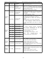
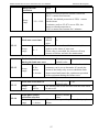
4.1.3 Key Button Description
Tab.4-1Keyboard function table
47
Operation and Display
M420 General Flux Vector Control Inverter User Manual
Button
Name
PRG/ESC
Program/ Exit
entry or exit ,return to primary menu
Function
ENTER
entry into the menu interface ,confirm the setup
parameters
increase (+)
Increase in the data or function code
decrease (-)
Decrease in the data or function code
select the displayed parameters in turn on the sto
》
shift key
display interface and running display interface ,and
select the modification digit of parameters when
modifying parameters.
RUN
Run key
used in running operation under keyboard control
mode
In the status of running ,pressing it can stop the
STOP/RESET
STOP/RESET
running
operation;in
fault
alarm
,can
reset
operation,this barton cara teristic is limited by the
function code F7-02
F7-28 is to set 0 it indicates quick key, F7-28 is to
QUICK/JOG
QUICK/JOG
set 1,it shows Jog key,then pressing this key shows
in reverse
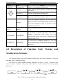
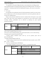
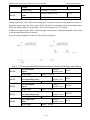
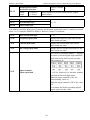
4.2 Description of Function Code Viewing and
Modification Methods
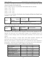
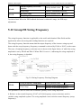
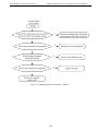
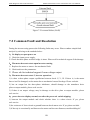
The operation panel of the M420 inverter adopts there level menu structure to carry out
operation such as parameter setting
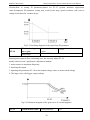
The three-level menu includes function parameter set (level 1 menu) →Function code
(level 2 menu) →Function code setup value (level 3). Refer to Fig.4-2 for the operation
procedure.
Fig .4-2 the operation procedure of three-level menu
48
M420 General Flux Vector Control Inverter User Manual
Operation and Display
Caution: when operation on level 3 menu,press PRG key or Enter key to return to level 2
menu. The difference between them is described as follows :Pressing Enter key will save the
setup parameter and return to the level 2 menu ,and then automatically shift to the next function
code ,while pressing PRG key will directly return to level 2 menu without saving the
parameter,and it will return to the current function code.
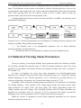
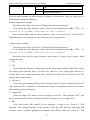
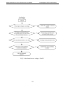
Example:Modify the function code F2-02 from 50.00H2 to 20.00H2 ( the bold-type work
indicated the flashing bit)
Fig.4-3 Example of parameter editing operation
Caution:in level 3 menu,if the parameter has no flashing bit ,it indicates that the function code
cannot be modified. The possible reasons include:
1 ) the function code is an unchangeable parameter such as actual detection
parameter,running record parameter,etc.
2)the function code is an unchageable in running ,and can be modified in stop
4.3 Method of Viewing Status Parameters
In stop or running ,it can display multiple status parameters,and select whether to display
the parameter through the function codes F7-29(Led running parameters) and F7-30 (stop
parameter) in accordance with binary bits.For the meaning of binary bits ,refer to Chapter 6
F7-29 and F7-30
In status of stop,there are seven stop status parameters for selection,namely:setup
frequency ,bus voltage,DI input status,DO output status,analog input A11 voltage,PLC running
step,the displaying of the selected parameters can be switched by pressing shift key in
sequence( displaying of parameters are converted into binary system by F7-30)
In running , there are thirteen running parameters displayed , five parameters are displayed
for running frequency ,setup frequency ,bus voltage,output voltage and output current ,other
eight parameters for output power ,DI input status, DO output status,analog input A11
voltage ,analog input A12 voltage ,PID setup,PID feedback and PLC,These parameters are
displayed in accordance with the selection of F7-29 (converted into binary system).The
displaying of the selected parameters can be switched by the button in sequence
When the inverter is restarted on power off,the displayed parameters are the selected
parameters before the power off.
49
Operation and Display
M420 General Flux Vector Control Inverter User Manual
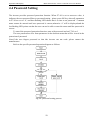
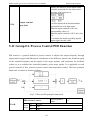
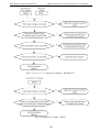
4.4 Password Setting
The inverter provides password protection function .When F7-49 is set to non-zero value, it
indicates the user password.Prior to password setting , please press OK key when all parameters
in F7-49 are set to ‘0’, and then flashing LED shows that it is time to set password . Common
menu cannot be entered until user password is correct,otherwise ‘0’ will be displayed,and the
last flashing LED points out that the user can not be able to enter the menu until the password is
correct
To cancel the password protection function ,enter with password and set F7-49 to 0
The user password are free from parameters in the shortcut menu that will be viewed in the
protection of password
Note:if the user forgets password so that this inverter can not work ,please contact the
manufacturer.
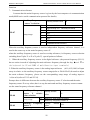
Refer to the specific password operation diagram as follows:
Fig.4-4: password setting process
50
M420 General Flux Vector Control Inverter User Manual
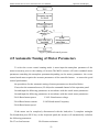
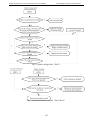
Operation and Display
Fig.4-5: password cancel process
4.5 Automatic Tuning of Motor Parameters
To select the vector control running mode ,it must input the nameplate parameter of the
motor accurately prior to the running of inverter,The M420 inverter will select standard motor
parameters matching the nameplate parameter;depending on the motor parameters ,the vector
control mode must acquire the accurate parameters of the controlled motor
to ensure the good
control performance
the procedures for the automatic tuning of motor parameters are described below
First,select the command source (F0-04)as the command channel of the operation panel
Second,input the following parameters in accordance with the actual motor parameters
Second,input the following parameters in accordance with the actual motor parameters
F4-01:Rated motor power
F4-02: Rated motor voltage
F4-04:Rated motor current
F4-05:Rated motor Frequency
F4-06:Rated motor speed
If the motor can be completely disconnected with the load,select 2 (complete tuning)in
F4-00,and then press RUN key on the keyboard panel,the inverter will automatically calculate
the following parameters
F4-07: no-load current
F4-08:stator resistance
51
Operation and Display
F4-09: Rotor resistance
M420 General Flux Vector Control Inverter User Manual
F4-10:mutual inductive reactance
F4-11:Leakage inductive reactance
Finally, complete the automatic tuning of motor parameters
If the motor cannot be totally disconnected with the load ,select 1 (static tuning without
rotation )in F4-00,and then press RUN key on the keyboard panel
Note: A suggestion from factory said that customer to select the way of
complete tuning which is able to help you acquire the motor parameters
more accurately.
52
M420 General Flux Vector Control Inverter User Manual
Parameter Description
Chapter 5 Parameter Description
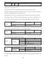
5.1 Group F0 Basic Function
F0-00
Software version
Factory default value
#.##
setup range
This parameter is provided only for the user to view the software version and cannot be
modified
Factory default
value
Model display
F0-01
setup range
0
For general purpose
1
For pump application
model dependent
This parameter is provided only for the user to view the model and cannot be modified
0: applied to the constant torque of the designated rated parameters
1: applied to the variable torque loads(fan and pump loads) of the designated rated parameters
Rated
current
Factory default value
setup range
0.1A~3000.0A
model dependent
F0-02
This parameter is provided only for the user to view the rated current and cannot be modified
Control mode
factory default value
1
(SVC1)open loop flux vector control 1
0
F0-03
Set
up 1
(SVC2) open loop flux vector control 2
range
2
V/F control
0:open loop vector control 1
This vector control is not sensitive to motor parameters , general, static tuning of motor
parameters can be stable and reliable running,and most of motor parameter can be connected
automatically in the process of running.such as no-load current ,lowest running frequency for
1H2,and is only for running below the fundamental frequency.
It is application to the general
high-performance control applications where on inverter can only drive on motor
53
Parameter Description
M420 General Flux Vector Control Inverter User Manual
1:open vector control 2
It is applicable to the general high-performance control applications including machine
tool,centrifugal machine,wire drawing machine,and injection molding machine ,all of them can
run the flux –weakening control below the fundamental frequency, one inverter can only drive
one motor
2:V/F control
It is applicable to the applications where the load requirement are rather low or one inverter
drives multiple motors such as fan and pump load,and can be used in the application where one
inverter drive multiple motors.
Prompt :motor parameter identification must be conducted when selecting the vector control
mode. Only when correct motor parameters are provided can vector control mode be taken
advantage of,Better performance can be achieved by adjusting the speed regulator
parameters(Group F3).
F0-04
Command
souse selection
0
setup
1
range
2
factory default value
0
operation panel command channel
terminal command channel
serial port communication command channel
Select control command channel for inverter
The inverter control command includes start ,stop,forward rotation ,reverse rotation and Jog.
0:operation panel command channel(LED OFF)
Perform running command control with key on the operation panel such as
RUN ,STOP/RES key
1:Terminal command channel (LED ON)
Perform running command control by the multifunctional input terminals ,such as FWD、
REV、JOGF、JOGR,etc.
2: Serial port command channel (LED flashes)
The running command is sent by the host computer via communication mode.
F0-06
Main frequency
source X
0
1
Set up range 2
3
4
Factory default value
0
digital setup UP、DOWN(non-recorded)
digital setup UP、DOWN(recorded)
AI1
AI2
MS speed
54
M420 General Flux Vector Control Inverter User Manual
5
6
7
Parameter Description
PLC
PID
Fixed communication
select the input channel for main reference frequency of the inverter.There are eight types of
main reference frequency channels:
0:digital setup(non-recorded)
The initial value is the value of F0-11”Digital Setup Present Frequency”
It can change the setup frequency value of the inverter through the key ▲and ▼on the
keyboard (or UP and DOWN of multifunction input terminals)
Non-recorded means that the setup frequency value is recovered to the value of F0-11
Digital Setup Present Frequency”in case of inverter power supply failure.
1:digital setup (recorded)
The initial value is the value of FO-11 Digital Setup Present Frequency”
It can change the setup frequency value of the inverter through the key ▲and ▼on the
keyboard (or UP and DOWN of multifunction input terminals)
Recorded means that the setup frequency upon restart of inverter due to power failed
remains the same
2:AI1
3:AI2
It means that the frequency is determined by the analog input terminal, M420 Driver offers
two analog input terminals ,that is ,A11and A12 ,and A11 is the voltage input from 0V to
10V,the other is the current input from 4mA to 20mA.all of them can be selected by the CN3
jumper on the control board.
4、MS speed
Select MS speed running mode in need of setting Goup F5 ‘Input Terminal and Group FC
“MS speed and PLC parameters to determine the relative relationship between the reference
signal and the reference frequency.
5、Simple PLC
Select the simple PLC mode in need of setting to Group FC “MS speed and “PLC” para
mete to determine the reference frequency when the frequency source is simple PLC ,
6、PID
Select the process PID control. In the meantime, it needs to set Group FA “PID
Function” .The running frequency of the inverter is that after PID functions. Regarding PID
reference source ,reference quantity,and feedback source.Please check the Group FA ‘PID
55
Parameter Description
M420 General Flux Vector Control Inverter User Manual
Function
7、Communication reference
It means that the main frequency source is given by the host computer via communication
mode(M420 series serial communication protocol for details)
Auciliary Frequency
source Y selection
F0-07
setup range
Factory default value
0
1
2
3
4
5
6
7
0
non-recorded
digital setup UP、DOWN(recorded)
AI1
AI2
MS speed
PLC
PID
communication reference
When the auxiliary frequency source is used as independent frequency reference channel ,it is
used in the same way as the main frequency source X
when the auxiliary frequency source is used as overlap reference (i.e.frequency source selection
switching from X plus Y or X to X puls Y) ,special points as follows:
1、When the auxiliary frequency source is the digital reference ,the present frequency (FO-11)
has no action in need of adjusting the main reference frequency through the key ▲and ▼on
the keyboard (or UP and DOWN of multifunction input terminals)
2、When the auxiliary frequency source is the analog input reference
(A11,A12) 100% of input
setup is relative to the auxiliary frequency source range(refer to F0-08-F0-09).In need to adjust
the main reference frequency ,please set the corresponding setup range of analog input to
“-n%to n%(refer to F5-15 and F5-24)
Prompt :there is difference between the auxiliary frequency source Y selection and the main
frequency source X set up value ,that is to say,the main and auxiliary frequency sources cannot
use the same frequency reference channel.
F0-08
F0-09
Auciliary Frequency
source
Y
relative
value selection
0
setup range
1
Auxiliary Frequency
source Y
setup range
Factory default
value
0
Relatively maximum frequency
Relatively frequency source X
default
Factory
0%
value
0%~100%
56
M420 General Flux Vector Control Inverter User Manual
Parameter Description
When the frequency source selection is the frequency overlap reference (F0-10 is set to 1or 3),it
is used to determine the adjustment range of the auxiliary frequency source.F0-08 is used to
determine the relative object of that range. For relatively maximum frequency(F0-14),its range
is fixed, if it is relative to the maximum frequency X,and its range will vary with the main
frequency X.
Frequency
source selection
0
1
2
F0-10
setup
range
3
4
5
Factory default value
0
X main frequency source X
Y main frequency source X+auxiliary frequency
source Y
Switching between the main frequency source X and
the auxiliary frequency source Y
Switching between the main frequency source X and
(the main frequency source X+ the auxiliary
frequency source Y)
Switching between the auxiliary frequency source Y
(the main frequency source X+ the auxiliary
frequency source Y)
Maximum of the main frequency source X and of the
auxiliary frequency source Y
This parameter is used to select the frequency reference channel .Frequency reference is realized
through combination of the main frequency source and the auxiliary frequency source
When 1 is selected,the frequency source “main frequency source X+ the auxiliary frequency
source Y can realize frequency overlapping function.
When 2 is selected,it can switch between the main frequency source X and the auxiliary
frequency source Y through the multifunctional input terminal”Frequency Source Switching”
When 3 is selected,it can switch between the main frequency X and (main frequency source X
puls auxiliary frequency source Y by he multifunctional input terminal”Frequency Source
Switching
When 4 is selected ,it can switch between the auxiliary frequency source Y and (main frequency
source
X
puls
auxiliary
frequency
source
Y)through
the
multifunctional
input
terminal”Frequency Source Switching”
In this way, it can realize mutually switching between the frequency reference modes such
as switching between PID running and common running ,simple PLC and common
running ,analog setup and command running.
When 5 is selected ,it can operate by choosing the maximum of frequency source between the
57
Parameter Description
M420 General Flux Vector Control Inverter User Manual
main frequency source and auxiliary frequency source
F0-11
Preset
frequency
factory default value
setup range
0.00 to max.frequency F0-14(active when the frequency
source selection mode is digital setup)
50.00Hz
When the main frequency source is selected as “Digital setup” or “Terminal UP/DN”,this
function code is the initial value of
Running
direction
F0-13
setup range
frequency digital setup of the inverter.
Factory default value
0
0
direction is consistent
1
2
Direction is reverse
no reverse
Through modifying this function code, it can change the rotary direction of the motor without
changing any other parameters ,The role of this function is to act the conversion of the motor
rotary direction by adjusting any two lines of the motor (U ,V and W).
Prompt :After parameter initialization,the motor running direction will restore to the original
status ,this action shall be carefully performed in the application where the rotary direction of
the motor is not allowed to change on system commissioning.
F0-14
Maximum
frequency
setup range
Frequency
source of
upper limit
F0-15
setup
range
factory default value
50.00Hz
50.00Hz~400.00Hz
factory default value
0
1
2
3
0
F0-16 setup
AI1
AI2
communication setup
It is used to define the source of frequency upper limit that can be from digital setup (F0-16) and
from analog input channel.when the analog input is to set the frequency upper limit .100%of
analog input setup is relative to F0-14.
For example,in case of torque control ,the speed control is inactive.To avoid occurrence of
broken materials,it can use the analog value to set the frequency upper limit.when the inverter
runs at the frequency upper limit, the torque control is inactive,and the inverter continues
running with frequency upper limit.
58
M420 General Flux Vector Control Inverter User Manual
Frequency upper
F0-16
F0-17
setup range
Frequency upper
limit offset
setup range
Parameter Description
factory default value
50.00Hz
frequency lower limit F0-18 to maximum
frequency F0-14
factory default value
0.00Hz
0.00Hz to maximum frequency F0-14
When the frequency upper limit is analog value reference ,this parameter is used as analog value
offset ,its reference value is F0-14.the addition of offset frequency and analog setup value of
frequency upper limit are used as the final setup value of frequency upper limit.
F0-18
Frequency lower limit factory default value
0.00Hz
setup range
0.00Hz to frequency upper limit F0-16
The inverter starts from the start frequency.If the reference frequency is lower than frequency
lower limit in the running process ,the inverter will keep running under frequency lower limit
until it stop s or the reference frequency is higher than the frequency lower limit.
F0-23
Speed-up time 1
20.0s
factory default
value
20.0s
0.0s~3000.0s
setup range
F0-24
factory default
value
Speed –down time 1
0.0s~3000.0s
setup range
speed-up time 1 refers to the time t1 require for the inverter to speed up from 0H2 to the
maximum output frequency (F0-14)
Speed-down time 1 refers to
the time t2 require for the inverter to speed down from the
maximum output frequency to 0H2.
Fig.5-1 Schematic diagram for acceleration /deceleration time
59
Parameter Description
M420 General Flux Vector Control Inverter User Manual
Pay attention to the difference between the actual acceleration /deceleration time and the
setup acceleration /deceleration time.
there are totally four groups of acceleration /deceleration time for selection.
Group 1:F0-23、F0-24;
Group 2:F7-03、F7-04;
Group 3:F7-05、F7-06;
Group 4:F7-07、F7-08;
It can select the acceleration /deceleration time through multifunctional digital input
terminals(F5-00~F5-04)
F0-25
The over modulati
on
function
selection
Factory value
The setting range
0: the over modulation function invalid
1: over modulation function
1
The over modulation function for grid voltage is too low or heavy load situations, improve the
inverter output voltage effective value
Carrier
frequency
setup range
F0-26
factory default
value
1.0kHz~15.0kHz
model dependent
This function is used to adjust the carrier frequency of the inverter.By adjusting the carrier
frequency ,the motor noise can be down,.and the resonance of the mechanical system ca be
avoided ,so that the leakage current to the Earth and the interference of the inverter can be
reduced
When the carrier frequency is low,the output current higher harmomic component will
increase,the motor loss will increase,and the motor temperature rise will also increase.
When the carrier frequency is high ,this motor loss is reduced,and the motor temperature is
decreased,but
both inverter loss and temperature rise will increase and so will the interference.
the adjustment of carrier frequency will have influences on the following:
carrier frequency
low
→
high
motor noise
high
→
low
output current waveform
poor
→
good
motor temperature rise
high
→
low
Inverter temperature rise
low
→
high
leakage current
low
→
high
external radiation interference
Low
→
high
60
M420 General Flux Vector Control Inverter User Manual
Parameter Description
Inverter power
carrier frequency range
carrier frequency
1.5Kw~7.5Kw
1.0kHz~15.0kHz
6.0kHz
11Kw~90Kw
1.0kHz~15.0kHz
4.0kHz
110Kw~700Kw
1.0kHz~15.0kHz
2.0kHz
Cautions: the inverter runs above the carrier frequency , each which of increasing 1KH2,it is
used in need to decrease 5%
F0-27
Carrier frequency adjustment
factory
0
selection
default value
fixed PWM,carrier frequency temperature adjustment
0
inactive
random PWM, carrier frequency temperature
1
adjustment inactive
setup
range
PWM,carrier frequency temperature adjustment
2
inactive
random PWM, carrier frequency temperature
3
adjustment active
The PWM carrier frequency adjustment mode offer two types,fixed and random.The motor
noise with random PWM has wide frequency range,and with fixed PWM has fixed frequency.
When the carrier frequency temperature adjustment remains active ,the inverter can
automatically adjust the carrier frequency according to its temperature.This function can reduce
the possibility of the inverter alarm because of its overheating
Parameter
initializatio
n
F0-28
setup range
factory default value
0
0
none
1
2
3
restore factory default value
previous user parameters upon power failure
fault record
5.2 Group F1 start/stop control
61
Parameter Description
M420 General Flux Vector Control Inverter User Manual
Start mode
F1-00
setup
range
0
1
factory default
0
value
direct start
(when DC break time is non- zero value,
perform DC braking before getting start)
speed tracking restart
0:Direct start
If the DC brake time is set to 0,it will start at the start frequency.
When the DC brake time is non-zero value ,it can perform DC braking before getting
start ,which suits for the applications where reverse rotation is likely to occur when small loads
are getting start
1:Speed tracking restart
First of all ,the inverter makes an estimate of motor speed and direction ,then starts at the
frequency in accordance with the tracked motor speed.the rotating motor is running smoothly
without surge.
It is suitable for the restart upon transient power failure of large loads.
Start model
F1-01
setup
range
0
1
2
factory default
0
value
beginning from the frequency on power failure
beginning from zero speed
beginning from maximum frequency
to complete the speed tracking process within the shortest time ,and then to select the mode of
inverter tracking motor speed.
0:to track from the frequency on power failure ,generally ,it selects this mode.
1:this mode is used to track from zero frequency and restart after a long period of power supply
off .
2:This mode is used to track from the maximum frequency, and is suitable for the general power
generating loads.
F1-02
F1-03
Speed tracking
maximum current
setup range
Speed tracking
fastness and
slowness
setup range
factory default value
100%
30%~180%
factory default value
20
1~100
In speed tracking restart ‘s mode ,to select its fastness and slowness.the higher this parameter
value is ,the faster the tracking speed is ,but too high value may result in reliable tracking.
62
M420 General Flux Vector Control Inverter User Manual
F1-04
F1-05
F1-06
F1-07
Start up frequency
setup range
Start frequency
retention time
setup range
DC break current
at start
setup range
DC break time at
start
setup range
factory default
value
0.00Hz~10.00Hz
factory
default value
0.0s~36.0s
factory default
value
0%~100%
factory default
value
0.0s~36.0s
Parameter Description
0.00Hz
0.0s
0%
0.0s
DC break at start is used when the motor is getting to restart after stoping completely
If the start mode is the direct start, the inverter firstly performs DC break in accordance with the
DC brake current at start,and then starts running after setting to DC brake time at start.if it is set
to 0,the inverter directly starts without passing through the DC brake.
The higher the DC brake current is ,the higher the brake force is The DC brake current at start is
regarded as the percentage of rated current for inverter.
S curve
factory default
acceleration start
value
F1-09
time
0.00~25.00s
setup range
S-curve
factory default
acceleration end
value
time
F1-10
setup range
F1-11
F1-12
S curve
acceleration start
time
setup range
S-curve
deceleration end
time
setup range
0.00s
0.00s
0.00s~25.00s
factory default
value
0.00s
0.00s~25.00s
factory default
value
0.00s
0.00s~25.00s
This parameters is used to set the drives with non-impact slow start at the beginning to start
acceleration .the acceleration/deceleration curve will adjust S-curve acceleration/deceleration at
the different degree by setup value.Using the S-curve slow acceleration /deceleration ,the drives
can make the different acceleration /deceleration curve based on the original of its time.
63
Parameter Description
M420 General Flux Vector Control Inverter User Manual
acceleration time=0,S-curve function is inactive.
Fig.5-2 Schematic Diagram for S-curve Acceleration/deceleration
factory default
0
value
deceleration stop
free stop
Stop model
F1-13
setup range
0
1
0: deceleration stop
After the stop command,the inverter reduces the output frequency according to deceleration
mode and the defined acceleration /deceleration time ,and will stop after the the frequency drops
to zero
1:free stop
After the stop command ,the inverter will end the output immediately.The load will is free to
stop according to the mechanical inertia.
F1-14
F1-16
F1-17
Brake beginning
frequency at stop
setup range
DC brake current
at stop
setup range
DC brake time at
stop
setup range
factory default
0.00Hz
value
0.00Hz~maximum frequency
factory default
0%
value
0%~100%
factory default
0.0s
value
0.0s~36.0s
DC brake beginning frequency at stop :In the process of the deceleration stop , when it reach
this frequency,the DC brake stop begins
DC brake current at stop :it refers to the additive DC brake quantity.The higher this value is ,the
better the DC brake effect is.
DC brake time at stop :it refers to the additive time of DC brake quantity.when this value is
zero,it shows there is no DC brake process,and the inverter will stop according to the given
64
M420 General Flux Vector Control Inverter User Manual
Parameter Description
deceleration stop
F1-18
default
factory
100%
value
0%~100%
Brake use ration
setup range
It is enabled for the inverter with built-in unit,and used to adjust the brake effect of the bake unit
Power interruption
restart
F1-19
setup range
F1-20
F1-21
0
1
2
3
Permission time
on power supply off
setup range
Power interruption
recovery waiting
time
setup range
factory default
value
0
inactive
Start from stop frequency
Start from minimum frequency
direct start
factory default
1.0s
value
0.1s~5.0s
factory default
value
1.0s
0.1s~5.0s
After its power off , the inverter is getting recovery whether to start as options .When F1-19 is to
set 0,it shows that the inverter can not automatically restart until running command is sent ,the
other setting values ,within permissible time(F1-20)for its power failure and waiting time(F1-21)
for its power recovery,the inverter will restart according to setting mode.
F1-23
F1-24
Transient stop/
non-stop function
selection
0
setup range
1
Transient stop/
non-stop frequency
reduction rate
0
1
setup range
2
3
factory default
value
1
Invalid
Valid
factory default
value
1
Select speed-down time 1(F0-23/F0-24)
Select speed-down time 2(F7-03/F7-04)
Select speed-down time 3(F7-05/F7-06)
Select speed-down time 4(F7-07/F7-08)
When the application situation has no electrical source
,taking advantage of this function
makes motor speed down to zero in deceleration mode,meanwhile, the inverter can restart in
recovery time
65
Parameter Description
M420 General Flux Vector Control Inverter User Manual
5.3 Group F2 V/F Control Parameters
This group function is only for V/F control(F0-03=2), not for the vector control.
V/F control is applicable to the general loads such as fan and pump or the applications where
one inverter drives multiple motors or the inverter power is one level lower or higher than the
motor power
Curve setup
F2-00
setup range
0
1
2
factory default
0
value
straight V/F curve
multiple point V/F curve
square VF curve
The fan and pump load can select square V/F control
0: straight V/F curve,it is suitable for common constant torque load
1: multiple point V/F curve ,it is suitable for the special loads such as dehydrator and center
fugal machine.
2:square V/F curve.it is suitable for the centrifugal loads such as fan and pump.
factory default
Torque boose
3.0%
value
F2-01
0.0%~30.0%
setup range
Cut off frequency of factory default
30.00Hz
torque boose
value
F2-02
0.00Hz~maximum output frequency
setup range
To compensate the low frequency torque characteristic of V/F control ,it can boost the output
voltage of the inverter at the time of low frequency
the torque boose is set to be large ,which cause motor over heat and the inverter over current.In
general, the torque boost shall not exceed 8%.
Adjusting this parameter effectively can avoid over current on star up.For the relatively large
loads,it is recommend to increase this parameter.For the small loads ,this parameter value can be
decrease.
When the torque boost is set to 0.0,the inverter can adopt auto-torque boost.
Cutoff frequency of torque boost :under this frequency ,the torque boost is active.If it exceeds
this setup frequency ,the torque boost is inactive.Refer to Fig. 5-3 for details.
66
M420 General Flux Vector Control Inverter User Manual
Parameter Description
Fig.5-3 Diagram for Manul Torque Boost
F2-03
F2-04
F2-05
F2-06
F2-07
F2-08
V/F Frequency
Point 1 F1
setup range
V/F voltage Point 1
V1
setup range
V/F Frequency
Point 2 F2
setup range
V/F voltage Point 2
V2
setup range
V/F Frequency
Point 3 F3
setup range
V/F voltage Point 3
V3
setup range
factory default
40.00Hz
value
0.00Hz~rated frequency for motor
factory default
300.0V
value
0.0V~380.0V/0.0V~220.0V
factory default
20.00Hz
value
0.00Hz~rated frequency for motor
factory default value 170.0V
F1~380.0V/220.0V
factory default
5.00Hz
value
V2~rated frequency for motor
factory default
42.0V
value
F2~380.0V/220.0V
F2-03~F2-08 Six parameters define MS V/F curve.
The setup value of V/F curve is generally set in accordance with the load caracteristics of the
motor.
Caution: V1>V2>V3,F1>F2>F3.In case of low frequency ,higher setup voltage can make
motor overheat and even burned,and make the inverter over current or current protection .
67
Parameter Description
M420 General Flux Vector Control Inverter User Manual
Fig.5-4 schematic diagram for V/F curve setup
F2-09
Slip compensation
coefficient
factory default
value
setup range
0.0%~200.0%
0.0%
It is enable only for V/F control.Setting this parameter can compensate the slip in the V/F
control mode due to load and reduce the change of rotation speed of the motor following the
load change.In general 100% corresponds to the rated slip of the motor with rated load.Slip
coefficient adjustment can refer to the following principles:when the load is rated load and the
slip compensation coefficient is set to 100%,the rotation speed of the motor in the inverter is
close to the given speed.
Magnetic brake gain
factory default
value
setup range
0%~200.0%
F2-10
80%
In the V/F control mode, when it needs fast stop and there is no brake resistor,selecting ‘inactive
only at the time of deceleration’can greatly reduce the possibility of overvoltage fault
alarm.When there is brake resistor or it has not need for fast deceleration ,select “active”
F2-11
Oscillation
suppression gain
setup range
factory default
value
0~100
20
Select “0” for this gain when the motor has no oscillatin.Only when the motor has obvious
oscillation and cannot run normally can this gain be properly increased.The bigger than gain
is ,the better oscillation suppression result will be.The method of selecting this gain is to select
the smallest one on the premise that there is effective oscillation suppresion measure,so as to
ease the negative effect on the VF operation.
68
M420 General Flux Vector Control Inverter User Manual
Parameter Description
In the process of no-load or light load running,the motor can properly adjust output voltage so as
to reach the purpose of auto-energy saving by the test of load current . This feature is active for
loads such as fan and pump
5.4 Group F3 Vector Control Parameters
Group F2 function code is only for the vector control,that is to say , F0-03= 0 shown active,
F0-03=1shown inactive.
F3-00
Switching frequency
F1
setup range
F3-02
switching frequency
F2
setup range
F3-04
F3-05
F3-06
F3-07
Speed
proportional gain of
1
setup range
Speed integral
time 1time
factory default
value
0.00Hz~F3-02
5.00Hz
factory default
10.00Hz
value
F3-00~The maximum frequency
factory default
value
1.00
0.500s
setup range
0.001~9.999
factory default
value
0.001~9.999s
Speed proportional
gain of 2
factory default
value
0.800
setup range
0.001~9.999
Speed integral time 2
setup range
factory default
value
0.001s~9.999s
1.000s
The speed dynamic response characteristics of the vector control can be adjusted by setting
the proportional coefficient and integration time of the speed regulator.Increasing the
proportinal gain or reducing the integration time can accelerate the dynamic response of the
speed loop.whatever the proportinal gain is too large or the integration time is too short can
cause the oscilltion of the system.
Proposed adjustment method:
If the factory default parameters can not meet the requirements ,the relevant parameters
values can be subject to fine tuning.On
increasing the proportional gain ,it ensures no oscillation to the system .and then reducing the
integration time to make the system both quick response characteristic and small overshoot
69
Parameter Description
M420 General Flux Vector Control Inverter User Manual
Caution:Prior to setting PI parameters,please set F3-15 (system inertia)to appropriate
value.Or,improper PI parameter setting may result in the large speed overshoot ,and even in
voltage fault when the vershoot drops.
Fig.5-5 Switching diagram of the speed loop PI parameter
F3-10
Flux weakening
curve gain
factory default
value
setup range
20%~150%
100%
Entering into output in flux weakening area, the user may adjust F3-10.
mainly aimed at axia’s application ,adjustment method;
1. motor comes to maximum frequency
2. checking the output
3. adjusting the parameters F3-10 so that output voltage comes to motor rated voltage
4. The larger value ,the bigger output voltage
Fig.5-6 Schematic diagram of the gain curve of a weak magnetic
F3-15
System inertia value
factory default
70
64
M420 General Flux Vector Control Inverter User Manual
setup range
Parameter Description
value
1~65535(0.0001kg*m^2)
This parameter which is for motor load inertia needs to set an appropriate value before the motor
runs,can cause the system unstable because of its value is too big or too small,at this time it can
adjust the speed loop proportional gain and inter gration time to increase the system
performance
F3-16
Torque boost at low
frequency
setup range
factory default
value
0%~200%
100%
This parameter is used in vector control 1 starting torque boost at low frequency ,the larger
its value,the higher low frequency torque ,but all of this may cause no-load current too higher. In
the case of driving the load , the smaller its value is , the lower motor temperature rise is at the
low frequency .
F3-17
Slip compensation
coefficient
setup range
factory default
value
50%~200%
100%
For the speedless sensor vector control,this parameter is used to adjust the stabilizing speed
precision for motor,when the speed is too large ,this parameter needs to be decreased, on the
contrary,it needs to be enlarged.
Time constant of
speed command
setup range
factory default
value
0.000s~0.100s
0.000s
F3-18
Time constant of
speed loop
setup range
factory default
value
0.000s~0.100s
0.000s
F3-19
In the vector control mode, the output of speed loop regulator is a torque current command.This
parameter is used to filter the torque command ,generally, is in no need to adjust,and the filter
time can be increased in case of huge speed fluctuation,In case of oscillation of motor ,,this
parameter shall be decreased properly.,
The time constant of speed loop filter is low,and the output torque on the inverter may be
change a lot,but its response is quick.
71
Parameter Description
M420 General Flux Vector Control Inverter User Manual
Torque upper limit
source
F3-20
setup range
0
1
2
F3-21
AI1
AI2
3
communication setup
Torque upper limit
F3-21
setup range
factory default
value
factory default
value
0%~200%
0
180%
F3-20 is used to select the setup source of torque upper limit ,when setting via the analog
value,100% of the analog input setup corresponds to F3-21,and the setup 100% of F3-21
corresponds to the rated torque of the motor matching the inverter
factory default
1
Vector AVR
value
F3-24
0~2
setup range
F3-24 is used for vector control AVR processing, 0: the whole effective, 1: the whole is
invalid,
only
2:deceleration
is invalid.
When the AVR
is invalid,
can make
the speed faster, but more current, easy over voltage occasions during deceleration, suggest
that F3-24 is set to 1 or 2. In the inverter configuration of brake unit orenergy feedback
unit occasions, suggest that F3-24 is set to 0
5.5 Group F4 Motor Parameters
Motor tuning
selection
F4-00
setup range
0
1
2
factory default
value
none
static tunning
complete tuning
0
Caution:Prior to tuning ,it must set the correct motor rated parameters (F4-01~F4-06)
0: None ,that is ,No-Tuning
1:Static tunning ,it is suitable for this occasion that on which motor and load is hard to take off
so as to not get the rotary tunning
Operation description:setting this function code to 1 and then pressing the RUN key with
72
M420 General Flux Vector Control Inverter User Manual
Parameter Description
confirmation ,the inverter will operate static tuning
2: complete tuning
To ensure the dynamic control performance on the inverter,please select the rotary tunning,the
motor must be disconnected with the loads (i.e.no-load)in the process of the rotary tuning.
Upon selection of rotary tuning ,the inverter will conduct static tuning at first.at the end of static
tunning ,the motor will accelerate to 80% of the rated motor frequency in accordance with the
setup acceleration time of F4-12 and maintain for a period of time. Then the motor will
decelerate to zero speed in accordance with the setup acceleration time of F4-13,by this time the
rotary tuning is finished.
Operation description :setting this function code to 2 and pressing RUN key with
confirmation ,then the inverter will operate rotary tuning
tuning operation description
When F4-00 is set to 1or 2 ,press ENTER key ,’TUNE will be displayed and flashed,then press
RUN key to operate parameter tuning,at this time the displayed TUNE stops flashing. After the
tuning is completed ,the display will return back to stop status interface ,In the process of tuning,
pressing this STOP key can be stopped
The value of F4-00 will automatically restore to 0 at the end of tuning.
Rated power
F4-01
setup range
Rated voltage
F4-02
setup range
Motor poles
F4-03
F4-04
setup range
Rated current
setup range
Rated frequency
F4-05
setup range
Rated rotation speed
F4-06
setup range
F4-07
No load current
setup range
factory default
model dependent
value
0.4kw~1000.0kw
factory default
380V
value
0V~440V
factory default
4
value
2~64
Factory default
Model dependent
0.00A~3000.0A
factory default
50.00Hz
value
0.00Hz~max frequency
factory default
1460rpm
value
0 rpm~30000rpm
factory default
model dependent
value
0.1A~1500.0A
73
Parameter Description
M420 General Flux Vector Control Inverter User Manual
Stator resistance
F4-08
setup range
Rotor resistance
F4-09
setup range
Mutual inductive
reactance
setup range
Leakage inductive
reactance
setup range
Complete tuning
acceleration
setup range
Complete tuning
deceleration
setup range
F4-10
F4-11
F4-12
F4-13
注意
factory default
model dependent
value
0.001Ω~65.535Ω
factory default
model dependent
value
0.001Ω~65.535Ω
factory default
model dependent
value
0.1mH~6553.5mH
factory default
model dependent
value
0.01 mH~65.535mH
factory default
5000
value
1~60000
factory default
5000
value
1~60000
caution
1、Please set this parameters according to the nameplate parameters of the motor
2、It needs accurate motor parameter to ensure the excellent control performance of the vector
control. Accurate parameter identification comes from the correct setting of the rated motor
parameters.
3、In order to ensure the control performance ,please carry out motor configuration in
accordance with the standard adaptable motor on the inverter.If there is huge difference
between the motor power and the power of standard adaptable motor,the control
performance on the inverter will decrease obviously.
5.6 Group F5 Input Terminal
The standard unit of M420 series inverter has 5 multi functional digital input terminals and 2
analog input terminals.if the system needs more input/output terminals ,M420 series inverter is
the best choice.
F5-00
F5-01
DI1 terminal
function selection
DI2 terminal
function selection
factory default
value
factory default
value
74
1(forward rotation)
2(reverse rotation)
M420 General Flux Vector Control Inverter User Manual
F5-02
DI3 terminal
function selection
DI4 terminal
function selection
DI5 terminal
function selection
DI6 terminal
function selection
DI7 terminal
function selection
F5-03
F5-04
F5-05
F5-06
Parameter Description
factory default
value
factory default
value
factory default
value
factory default
value
factory default
value
9(fault-reset)
12(MS speed 1)
13(MS speed 2)
0 (non functional)
0 (non functional)
This parameter is applied to set the functions on multifunctional digital input terminals
setup
function
value
即使有信号输入变频器也不动作
0
none
description
Even when there is signal input, the inverter still
has no action. The no operation function can be
set on the unused terminals so as to prevent error
action.
1
2
3
4
5
Forward rotation
(FWD)
Reverse rotation
(REV)
Control the forward rotation and reverse rotation of the
inverter via the external terminals.
Three-line mode
running control
This terminal is used to confirm that the inverter running
mode is three-line control mode For detailed description,
please refer to F5-11 three-line control mode function
code.
Forward rotation
Jog
(FJOG)
Reverse rotation
Jog
(RJOG)
FJOG refers to Jog forward rotation, while RJOG refers
to Jog reverse rotation. For details regarding frequency
and Jog acceleration/deceleration time during the Jog
running, refer to F7-00, F7-01 and F7-02 function codes.
6
Terminal UP
7
Terminal DOWN
8
Free stop
When the frequency is given by the external terminals, it
is used as increment and decrement commands of
frequency modification When the frequency source is
set to digital setup, it can be used to adjust the setup
frequency.
The inverter locks the output, and the motor stop process
is beyond the inverter control. It is the general method
adopted when there is huge load and no requirement for
the stop time.
This mode is the same as the meaning of coast to
stop as described in F7-26.
75
Parameter Description
setup
value
M420 General Flux Vector Control Inverter User Manual
function
9
Fault reset
(RESET)
10
Running pause
11
12
13
14
15
16
17
External fault
normally open
input
MS speed terminal
1
MS speed terminal
2
MS speed terminal
3
MS speed terminal
4
Speed-up/speed-do
wn time selection
terminal 1
Speed-up/speed-do
wn time selection
terminal 2
18
Frequency source
switching
19
UP and DOWN
setup clear
(terminal and
keyboard)
description
External fault reset function. It is the same as the
function of RESET key on the keyboard. Using this
function can realize long-distance fault reset.
The inverter decelerates to stop, but al l the running
parameters are al l in the memory status, such as PLC
parameter, swing frequency parameter and PID
parameter. After this signal disappears, the inverter
restores to the status before stopping.
After the external fault signal is sent to the inverter, the
inverter reports fault and stops.
It can realize 16S speed through the combination of
digital status of these four terminals. Refer at attached
table 1 for the MS speed function ion description.
It can select four types of speed-up/speed-down time
through the combination of digital status of these two
terminals.
Refer to table 2.
When the frequency source selection (F0-10) is set to
2, it performs switching between main frequency
source X and auxiliary frequency source Y via this
terminal.
When the frequency source selection (F0-10) is set to
3, it performs switching between main frequency
source X and (main frequency X plus auxiliary
frequency source Y) via this terminal.
When the frequency source selection (F0-10) is set to
4, it performs switching between auxiliary frequency
source X and (main frequency X plus auxiliary
frequency source Y) via this terminal.
When the frequency reference is digital frequency
reference, this terminal can be used to clear the
frequency value modified by UP/DOWN and thus
restore the reference frequency to the setup value of
76
M420 General Flux Vector Control Inverter User Manual
setup
value
function
20
Running command
switching terminal
21
Speed-up/speeddown active
22
PID Pause
23
PLC status reset
24
Swing frequency
pause
25
Timer trigger input
26
Brake command
27
External fault
normally closed
input
Parameter Description
description
F0-11.
When the command source (F0-04) is set to 1, it
performs switching between terminal control and
keyboard control via this terminal.
When the command source (F0-04) is set to 2, it
performs switching between communication control and
keyboard control via this terminal.
Protect the inverter from affecting by the external
signals (except stop command), and maintain the current
frequency
PID is inactive temporarily, and the inverter maintains
the current frequency output.
PLC pauses during the execution process. When it
resumes running, it can effectively restore to the initial
status of simple PLC via this terminal.
The inverter output with central frequency. Swing
frequency pauses.
Closing time depends on F7-39,See details F7-39~
F7-40
This terminal is enabled, and the inverter directly
switches to the DC brake status.
After the external fault signal is sent to the inverter, the
inverter reports fault and stops.
Table 1 MS Speed Function Description
K4
K3
K2
K1
Frequency
Corresponding Parameter
Setup
OFF
OFF
OFF
OFF
MS speed 0
FC-00
OFF
OFF
OFF
ON
MS speed 1
FC-01
OFF
OFF
ON
OFF
MS speed 2
FC-02
OFF
OFF
ON
ON
MS speed 3
FC-03
OFF
ON
OFF
OFF
MS speed 4
FC-04
OFF
ON
OFF
ON
MS speed 5
FC-05
OFF
ON
ON
OFF
MS speed 6
FC-06
OFF
ON
ON
ON
MS speed 7
FC-07
77
Parameter Description
K4
K3
M420 General Flux Vector Control Inverter User Manual
K2
K1
Corresponding Parameter
Frequency
Setup
ON
OFF
OFF
OFF
MS speed 8
FC-08
ON
OFF
OFF
ON
MS speed 9
FC-09
ON
OFF
ON
OFF
MS speed 10
FC-10
ON
OFF
ON
ON
MS speed 11
FC-11
ON
ON
OFF
OFF
MS speed 12
FC-12
ON
ON
OFF
ON
MS speed 13
FC-13
ON
ON
ON
OFF
MS speed 14
FC-14
ON
ON
ON
ON
MS speed 15
FC-15
Table 2 MS Speed Function Description
Terminal
2
OFF
OFF
ON
ON
F5-10
Terminal
1
OFF
ON
OFF
ON
Speed-up/speed-down
time selection
Speed-up time 1
Speed-up time 2
Speed-up time 3
Speed-up time 4
DI filter time
Setup range
Corresponding Parameter
Factory default value
0ms~100ms
F0-23、F0-24
F7-03、F7-04
F7-05、F7-06
F7-07、F7-08
10ms
It is used to set the sensitivity of DI terminal.If the digital input terminal is vulnerable to
interferences and may cause error action, it can increase this parameter value to enhance the
anti-interference capability. However, this operation will reduce the sensitivity of DI terminal.
F5-11
Terminal
command mode
0
1
Setup range
2
3
Factory default value
0
Two-line mode 1
Two-line mode 2
Three-line mode 1
Three-line mode 2
This parameter defines four different modes of controlling the operation of the inverter via
the external terminals.
78
M420 General Flux Vector Control Inverter User Manual
Parameter Description
0: Two-line running mode 1: This mode is the most commonly used two-line mode. The
forward/reverse rotation of the motor is decided by the commands of FWD and REV terminals.
Fig.5-7 Two-line Running Mode 1
1: Two-line running mode 2: When this mode is adopted, REV is enabled terminal.
The direction is determined by the status of FWD.
Fig.5-8 Three-line Running Mode 2
2: Three-line running mode 1: In this mode, Dln is enabled terminal, and the direction is
controlled by FWD and REV respectively. However, the pulse is enabled through disconnecting
The signal of Din terminal when the inverter stops
Fig.5-9 Three-line Running Mode 1
Where:
SB1: Stop button
SB2: Forward rotation button
79
Parameter Description
M420 General Flux Vector Control Inverter User Manual
SB3: Forward rotation button
Dln is multifunctional input terminals of DI1 to DI5.In this way, it shall define the
corresponding terminal functions as No.3 function “Three-line Mode Running Control”.
3: Three-line running mode 2: In this mode, Dln is enabled terminal, and the running command
is given by FWD, while the direction is determined by the status of REV. Stop command is
performed through disconnecting the DIn signal.
Fig.5-10 Three-line Running Mode 2
Where :
SB1: Stop button
SB2: Running button
Dln is multifunctional input terminals of DI1 to DI5. In this way, it shall define the
corresponding terminal functions as No.3 function “Three-line Mode running Control”.
Terminal
Factory default value
1.00Hz/s
UP/DOWN Speed
F5-12
0.01Hz/s~100.00Hz/s
Setup range
Terminals UP/DOWN is used to adjust the change rate when setting the frequency.
F5-15
F5-16
F5-17
F5-18
AI1 minimum
input
Setup range
AI1 minimum
input
corresponding
setup
Setup range
AI1 maximum
input
Setup range
AI1 maximum
input
corresponding
Factory default value
0.00V
0.00V~10.00V
Factory default value
0.0%
-100.00%~100.0%
Factory default value
10.00V
0.00V~10.00V
Factory default value
80
100.0%
M420 General Flux Vector Control Inverter User Manual
Parameter Description
setup
-100.00%~100.0%
Setup range
AI1 input filter
Factory default value
0.10s
time
F5-19
0.00s~10.00s
Setup range
The above function codes define the relationship between the analog input voltage and
analog input setup value. When the analog input voltage exceeds the setup maximum input or
minimum input range, the excess part will be calculated as maximum input or minimum input.
When the analog input is current input, 1mA current equals to 0.5V voltage.
In difference applications, 100% of analog input corresponds to different nominal values. Refer
to all the application parts for details.
Several setting examples are shown in the following figures:
Fig.5-11 Corresponding Relationship between Analog Reference and Setting
F5-20
F5-21
F5-22
F5-23
F5-24
AI2 minimum
input
Setup range
AI2 minimum input
corresponding setup
Setup range
AI2 maximum
input
Setup range
AI2 maximum input
corresponding setup
Setup range
AI1 input filter
time
Setup range
Factory
default value
0.00V~10.00V
Factory
default value
-100.00%~100.0%
Factory
default value
0.00V~10.00V
Factory
default value
-100.00%~100.0%
Factory
default value
0.00s~10.00s
81
0.00V
0.0%
10.00V
100.0%
0.10s
Parameter Description
M420 General Flux Vector Control Inverter User Manual
5.7 Group F6 Output Terminal
The standard unit of M420 series inverter has a multifunctional digital input terminal ,
multifunctional relay output terminal and analog output terminal,if need more relay output
terminals and analog output terminals.the M420 series is the best choice .
F6-00
Control board RELAY 1 output selection
F6-01
Control RELAY2 board relay output
selection
Y1 output selection
F6-02
factory default
value
factory default
value
factory default
value
2
1
1
The multifunctional digital output terminal function is for selection as follows
setup
value
Function
0
None
1
In running
2
Fault output
Description
no function
Express the inverter is running with output frequency (0 value
as option) given ON signal
The inverter is in trouble to output ON signal
Frequency
3
Level
detection
Refer to function code F7-22、F7-23 for details
FDT arrival
4
5
Frequency
arrival
In zero
The inverter output frequency is less than the start frequency
speed
so as to output ON signal
Motor
6
overload
pre-alarm
Inverter
7
Refer to F7-24 for details
overload
pre-alarm
To judge according to overload predicted values before the
motor electronic thermal protection take action, to exceed the
predicted values for ON signal.Motor overload parameter is set
to F9-00~F9-02
After checking the inverter overload,to move up early 10s
before the protection occurs, and to output ON signal
82
M420 General Flux Vector Control Inverter User Manual
8
9
10
11
12
Parameter Description
PLC cycle
To send a pulse signal with width of 250ms as simple PLC
finished
running at the end of one-time cycle
Running
The accumulated running time on the inverter is more than the
time off
setting time on F8-17 for ON signal
In
When the setting frequency exceeds the upper or lower
frequency
frequency ,and the inverter output frequency reach the upper or
limited
lower frequency,it gives ON signal.
Ready
for
running
AI1>AI2
The main circuit and control circuit ‘S power is established the
inverter is in running without protection to send ON signal
The analog input AI1 value is more than the other AI2 ‘s for
ON signal
Frequency
13
upper limit
the running frequency comes to the upper frequency
arrival
Frequency
14
lower limit
the running frequency comes to the lower frequency
arrival
Under
15
voltage
status
in the status of under voltage
output
16
Communica
tion setting
Timer
17
communication setting
When the set input terminal of a timer input function time after
output
the F7-39.this terminal is closed effective,such as invalid
function
invalid after F7-41 input terminal is disconnected this.
F6-09
AO1 output selection
F6-10
AO2 output selection
factory default
value
factory default
value
0
0
Standard output of the analog output (zero offset is 0, gain is one) is 0~20mA or 0~20mA
the corresponding value range is shown in the below table:
setup
value
function
range
83
Parameter Description
0
1
Running
frequency
Setup
frequency
M420 General Flux Vector Control Inverter User Manual
0~maximum output frequency
0~maximum output frequency
2
Output current
0~2 times of the motor rated current
3
Output power
0~2 times of the rated power
4
Output voltage
0~1.2 times of the inverter rated voltage
5
AI1
0~10V
6
AI2
0~10V/0~20mA
7
Communication
setup
refer to<M420 series inverter communication protocol>
shown as Appendix for details
F6-12
AO1 offset coefficient
setup range
F6-13
AO1 gain
setup range
F6-17
AO2 bias coefficient
setup range
F6-18
AO2 gain
setup range
factory default
0.0%
value
-100.0%~100.0%
factory default
1.00
value
-10.00~10.00
factory default
0.0%
value
-100.0%~100.0%
factory default
1.00
value
-10.00~10.00
if ‘b” represents zero offset,k represents gain , Y represents actual output,and X represents
standard output,the actual output is =kX+b
AO1 and A02 zero offset efficients 100% corresponds to 10V(20mA Standard output
refers to the output of 0 to 10V(20mA)corresponding to analog output of 0 to Maximum
It is generally used to correct the zero drift of the analog output and the output amplitude
deviation and also can be defined as any necessary output curve.
For example ,if the analog output is the running frequency ,it is expected to output 8V
(16mA),when the frequency is 0,and output 3V(6mA )at the maximum frequency ,the gain
shall be set to “-0.50”,and the zero offset shall be set to “80%”
84
M420 General Flux Vector Control Inverter User Manual
Parameter Description
5.8 Group F7 Auxiliary Function and Man-Machine
Interface Function
F7-00
F7-01
F7-02
Jog running
frequency
factory default value
setup range
0.00Hz~maximum frequency
Jog speed up time
factory default value
setup range
0.00s~3000.0s
Jog speed down
time
factory default value
setup range
0.00s~3000.0s
6.00Hz
20.00s
20.00s
.it is used to define the reference frequency and speed up/down time of the inverter on jogging
the Jog process is getting to started and to stop according to the start mode 0(F1-00,direct
start )and the stop mode 0(F1-13,speed down time to stop).
The Jog speed-up time means the time required for the inverter to accelerate from H2
maximum output frequency(F0-14)
The Jog speed-down time means the time required for the inverter to decelerate from the
maximum output frequency(F0-14)to 0H2
F7-03
F7-04
F7-05
F7-06
F7-07
F7-08
Speed up time 2
setup range
Speed down time 2
setup range
Speed up time 3
setup range
Speed-down
time 3
setup range
Speed up time 4
setup range
Speed-down
time 4
setup range
factory default value
0.0s~3000.0s
factory default value
0.0s~6500.0s
factory default value
0.0s~6500.0s
factory default value
0.0s~6500.0s
factory default value
0.0s~6500.0s
factory default value
0.0s~6500.0s
85
20.00s
20.00s
20.00s
20.00s
20.00s
20.00s
to the
Parameter Description
M420 General Flux Vector Control Inverter User Manual
Speed up/down time choose F0-23 , F0-24 and the above three types of speed up/down time ,all
of its meaning is the same .Refer to F0-23 and F0-24 for the detail
To select speed-up/down time 1to 4 in the process of running on the inverter by the different
combination of multi- functional digital input terminal DI , all the details are shown in F5-00~
F5-04.
F7-09
F7-10
F7-11
F7-12
F7-13
F7-14
Skip frequency 1
setup range
Skip frequency 2
setup range
Skip frequency 3
setup range
Skip frequency 4
setup range
Skip frequency 5
setup range
Skip frequency 6
setup range
factory default value
0.00Hz
0.00Hz~maximum frequency
factory default value
0.00Hz
0.00Hz~maximum frequency
factory default value
0.00Hz
0.00Hz~maximum frequency
factory default value
0.00Hz
0.00Hz~maximum frequency
factory default value
0.00Hz
0.00Hz~maximum frequency
factory default value
0.00Hz
0.00Hz~maximum frequency
When the setup frequency is within the skip frequency range, the actual running frequency will
be in the skip frequency boundary close to the setup frequency.
Fig.5-12 Schematic Diagram of Skip Frequency
F7-15
Forward/Reverse rotation
dead-zone time
setup range
factory default
value
0.0s~3000.0s
0.0s
During the setting of forward/reverse rotation on the inverter,the transition time in the output
zero frequency position is shown is the following figure
86
M420 General Flux Vector Control Inverter User Manual
Parameter Description
Fig.5-13 Schematic Diagram for Forward/Reverse Rotation Dead Zone Time
Rotate knob precision keyboa
rd
setup range
F7-16
F7-17
factory default
value
0~7
0
Set the value
The rotary knob accuracy
0
Restricted by the F7-25
1
0.1Hz
2
1Hz
3
2Hz
4
4Hz
5
5Hz
6
8Hz
7
10Hz
Setup frequency is
lower than frequency
lower limit action
setup range
factory default
value
0
1
2
0
run with the frequency lower limit
stop
run with zero speed
To select the status of running on the inverter when the setup frequency is lower than the
frequency lower limit.
In order to avoid the motor running with low speed, it can use this function to stop
87
Parameter Description
M420 General Flux Vector Control Inverter User Manual
factory default
value
0.00Hz~10.00Hz
Droop control
F7-18
setup range
0.00Hz
When the multiple inverters drive the same load,due to the different speed,the unbalanced load
distribution causes the inverter with faster speed to endure heavier load.The droop control
characteristic makes the speed droop change along with the addition load ,which lead to
balanced load distribution
F7-19
The delay time for frequency
is lower than the lower limit
at stop
setup range
factory default
value
300.0s
0.0s~600.0s
It is used to select in the status of stop when the setup frequency is lower than the frequency
lower limited action, and to delay F7-19 action time
F7-20
Setup running time
factory default value
setup range
0h~65535h
0h
the multifunctional digital DO on the inverter outputs the signal of running time arrival when the
accumulated running time (F7-34、F7-35)comes to this setup’s.
F7-22
F7-23
Frequency test
value(FDT level)
setup range
Frequency test
hysteresis(FDT
hysteresis)
setup range
factory default
50.00Hz
value
0.00Hz~maximum frequency
factory default
value
5.0%
0.0%~100.0%(FDT
level)
It is used to set the test value of out put frequency and hysteresis value on removing on the
output action
88
M420 General Flux Vector Control Inverter User Manual
Parameter Description
Fig.5-14 Schematic Diagram of FDT Level
F7-24
Frequency arrival test
amplitude
setup range
factory default
0.0%
value
0.0%~100.0% maximum frequency
when the output frequency on the inverter reaches the setup frequency value ,this function can
be used to adjust the test amplitude .as shown the following figure.
Fig.5-15 Schematic Diagram for Test Amplitude
Keyboard encoder accelera
factory default
0
tion level
value
F7-25
0~2
setup range
Used to adjust the keyboard encoder acceleration level, 0-- >2 accelerates more quickly, when
the adjusting knob speed of keyboard is not used, please adjust this parameter to
reach more convenient effect。
F7-26
Running time to
action selection
setup range
default
factory
value
keep running
stop
0
1
factory default
0
value
active in keyboard control mode
stop function is active under terminal
control
stop reset function is active under
terminal control
both stop and fault reset on stop key are
active under terminal control
STOP/RESET
Function
0
1
F7-27
setup range
0
2
3
89
Parameter Description
M420 General Flux Vector Control Inverter User Manual
Keyboard JOG
function
F7-28
0
setup range
F7-29
factory default
0
value
Jog function key
switching function key on
forward/reverse rotation
1
factory default value
LED operation
display
parameters
1~
16383
4095
setup
range
If the above parameter need to be displayed during the
operation,please set the corresponding position to 1,change the
binary numbers into decimal numbers and set them in F7-29
F7-30
LED stop display
parameters
setup
range
F7-31
factory default value
63
1 ~
511
If the above parameters need to be displayed in the status of
stop ,please set the corresponding position to 1 and change the
binary numbers into decimal numbers and set them in F7-30.
Load speed
factory default value
1.000
display
90
M420 General Flux Vector Control Inverter User Manual
Parameter Description
coefficient
0.001~10.000
setup range
The output frequency on the inverter and load speed have a correspondence with eath other by
the parameter, the need to display the load speed is to set , load speed=120*running
frequency*F7-31/motor pole-pairs numbers
F7-32
Radiator
temperature
setup range
factory default value
-
0℃~100℃
IGBT module ‘s temperature is displayed ,the different IGBT over-temperature protection value
may be different
F7-34
F7-35
Accumulated
running time
(minutes)
setup range
Accumulated
running time
(days)
setup range
factory default
value
0
0~1440
factory default
value
0
0~65535
To recoder the motor running time (the inverter drive enabled) is to set 0 and cancel ,when the
running time is less than 60s as shown no-recoder
Fan control
selection
setup range
F7-36
F7-37
Water supply
sleeping function
setup range
factory default
1
value
fan keeps running
stop running for one minute and stop
action with start /stop on the driver
checking the temperature on radiator to reach 50℃ and
then restart
0
1
2
3
factory default
0
value
0
invalidation
1
validation
This function is active ,and when
the frequency is less than the lower limit frequency
91
Parameter Description
M420 General Flux Vector Control Inverter User Manual
operation action (F7-17),it is used to select stop ,when frequency running comes to the lower
limit (F0-18),and the target frequency is less than the lower limit’s,after the
time on F7-19,it is
used to stop.; when the target frequency is higher than the lower limit’s ,inverter will restart
after the time on F7-38
F7-38
:DNHXS
pressure difference
setup range
factory default
value
0.0%~100.0%
3.0%
The above parameters are used to realize the wake-up function water applications.
This parameter is used to determine the minimum pressure of awakening, setting percentage for
a given pressure.
The lower limit value = PI given value - wake up wake pressure difference; pressure
difference = PI * F7-38.when PID value regulator feedback is less than the lower limit
value (pressure value is less than the lower limit value) inverter start running out of
hibernation, generally set at 3% ~ 10%.
Supply sleep setting procedure:
1, select the source frequency F0-06 = 6, PID given.
2, select the lower frequency F0-18 = dormancy frequency value, used to set
the resting frequency.
3, select the lower frequency F7-17 = 1, below the lower frequency down.
4, setting the minimum frequency of operation delay time F7-18
5, the selection of the water dormancy function on F7-37 = 1, is 1 water dormancy
function effect.
6, choose the sleep wakeup value F7-38 = calculated according to the differential
pressure value, for example,given 3 kilograms force, pressure is less than 2.5kilograms
of wake sleep function, FA-01=30.0%, F7-38 = 16%.
7, set the PID (FA) group of parameters.
Note: in the process of using PID, the start time frequency from 0 according to the acceleration
and deceleration time acceleration, after the arrival of the PID target value of switching to
PID PID complete control, adjust the timeless than the acceleration and deceleration time
according to the acceleration and deceleration time.
F7-39
F7-40
Timing time in the
status of DI -on
setup range
Timing time in the
status of DI-off
setup range
factory default
value
0.0s~6000.0s
factory default
value
0.0s~6000.0s
2.0s
2.0s
When the timer input terminal ‘connected “ is longer than F7-39. its function output is
connected.
When the timer input terminal ‘disconnected’ is longer than F7-40,its function output is not
connected.
92
M420 General Flux Vector Control Inverter User Manual
Parameter Description
Fig.5-16 Timer input and output action diagram
F7-41
Starting
protection
function
factory default
value
invalidation ( direct start when starting
terminal command is valid)
Validation
0
setup range
1
1
this parameters is used to improve the protection coefficient ,if set to 1,there ae two functions
1) When the running command is existed under power on ,it must be first to remove the
running command and then delete running protection
2)The running command is still existed when the inverter’s fault is to reset ,it must be first
to remove the running command and then delete running protection
these ways can prevent the motor auto-running under no awareness from happening
dangerous ,if set to 0 and the running command is existed under power on ,the inverter will
directly start after setting time on F7-42
F7-42
F7-49
Delay time for
direct start upon
power
setup range
factory default
value
1.0s
1.0s~60.0s
factory default
value
0~65535
User password
setup range
0
The user sets the password with this function. The setting methods refer to Password Setting on
Charpt 4 Operation and Display
5.9 Group F8 Communication Parameter Description
F8-00
factory default
value
Baud rate
setup range
0
300BPS
93
5
Parameter Description
M420 General Flux Vector Control Inverter User Manual
1
2
3
4
5
6
7
600BPS
1200BPS
2400BPS
4800BPS
9600BPS
19200BPS
38400BPS
This parameter is used to set the the data transfer rate between the host computer and the
inverter.
Caution: The baud rate of the host computer and the inverter must be consistent.Otherwise,
communication is impossible. The higher baud rate is, the faster communication is.
Data format
F8-01
setup range
0
1
2
factory default
0
value
No check:data format<8,N,2>
Even parity check :data format <8,E,1>
Odd parity check :data format<8,O,1>
The data format of the host computer and the inverter setup must be consistent, otherwise,
communication is impossible.
F8-02
Local
addr.
setup range
factory default
value
0~247,0 is broadcast address
1
The function code used to identify the local address of the inverter.The local address is unique
(except the broadcast address), which can realize the broadcast function of host computer.
Caution: When the local address is set to zero, that is the broadcast address, which can only
receive and perform the broadcast address of host computer but not respond to the host
computer.
F8-03
Response delay
setup range
factory default
value
10ms
0ms~20ms
Response delay: It refers to the interval time from the inverter finishes receiving data to sending
data to the host machine.If the response delay is less than the system processing time, then the
response based on the time delay of the system processing time.If the response delay is more
than the system processing time, after the system processes the data, it should be delayed to wait
until the response delay time is up, then sending data to host machine.
94
M420 General Flux Vector Control Inverter User Manual
F8-04
Parameter Description
factory default
value
0.0s(Invalid)~60.0s
Communication overtime
setup range
0.0s
When the function set to 0.0 s, the communication overtime parameter is invalid.When the
function set to 0.0 s, the communication overtime parameter is invalid. At normal circumstances,
it will be set as invalid. If in the continuous communication system, set the second parameter,
you can monitor the communication status.
The selection of the mode factory default
1
of communication
value
F8-05
0
Model free manufacturers
setup range
1
The standard MODBUS protocol
5.10 Group F9 Fault and Protection
Motor
overload protection
selection
F9-00
Factory
default
value
0
Inactive
1
Active
Setup
range
F9-01
0.20~
10.00
Motor over load
pre-warning
coefficient
F9-02
Setup
range
50%
100%
0: The inverter has no overload
protection for the motor, and thermal
relay is installed before the motor.
1: The inverter has overload protection
function for the motor. Refer toF9-01
for the protection value.
Factory
default
1.00
value
The motor overload protection is inverter time-lag
curve; 220%×(F9-01)× rated motor current: one
minute; 150%×(F9-01)× rated motor current: 60
minutes.
Motor overload
protection gain
Setup
range
1
~
Factory
default
80%
value
The reference for this value is the motor over load
cur rent . When the inverter detects that the output
current reaches (F9-02)× motor overload current
and lasts time as specified by the reverse time-lag
95
Parameter Description
M420 General Flux Vector Control Inverter User Manual
curve, it outputs pre-warning signal from DO or
relay
Stall gain over
voltage
F9-03
F9-04
Setup
range
0% ~
100%
Stall protection
voltage over
voltage
Setup
range
120% ~
150%
Stall gain over
current
F9-05
Setup
range
0% ~
100%
Factory
50%
default value
I t adjusts the inverter ’s capacity in suppressing the stall
over voltage. The bigger the value is, the stronger the
suppressing capacity is. For the load with small inertia, the
value should be small. Otherwise, the dynamic response of
the system will be slow. For the load with large inertia, the
value should be large. Otherwise, the suppressing result
will be poor, and over voltage fault may occur.
Factory
default
130%
value
Select the protection point for function of stall over
voltage. When the value is exceeded, the inverter starts
executing the protection function for stall over voltage.
Factory
80%
default value
It adjusts the inverter’s capacity in suppressing the stall
over current. The bigger the value is, the stronger the
suppressing capacity is. For the load with small inertia,
the value should be small. Otherwise, the dynamic
response of the system will be slow.
For the load with large inertia, the value should be large.
Otherwise, the suppressing result will be poor, and over
voltage fault may occur.
Stall protection
current over current
F9-06
Setup
range
F9-07
100% ~
200%
The overload
protection of the
Factory
default
180%
value
Select the protection point for function of stall over
current. When the value is exceeded, the inverter
starts executing the protection function for stall over
current.
Factory
default
96
100%
M420 General Flux Vector Control Inverter User Manual
motor current
coefficient
Setup
range
value
10%~100%
Fault auto reset times
F9-11
Setup
range
F9-12
0~3
F9-14
Motor overload protection current coefficient
F9.07 × motor rated current
(F4-04), the default protection is 220% × motor
rated current
1 minutes, such as: F9-07 is set to 50%, the
motor overload protection to
110% x motor rated current for 1 minutes.
Factory
default
0
value
When the inverter selects fault auto reset, it is
used to set the times of auto reset.
If this value is exceeded, the inverter will stop
because of failure and wait for maintenance
Fault relay action selection
Factory
1
during the fault auto reset
default value
After the failure auto reset function is selected, this
parameter can be set to determine if it needs the
0: No
Setup
action of the faulty relay so as to shield the fault
action
range
1: Action
alarm caused and ensure the continuous operation
of the equipment during the failure reset.
Fault auto reset interval
F9-13
Parameter Description
Setup
range
0.1s
100.0s
~
Input phase failure
protection selection
Setup
0: Inactive
range
1: Active
Factory
1.0s
default value
The waiting time of the inverter from the fault alarm
to auto reset.
Factory default
1
value
Select whether to provide protection for input phase
failure.
97
Parameter Description
F9-15
Output phase failure
protection selection
Setup
0: Inactive
1: Active
range
F9-16
First fault type
F9-17
Second fault type
F9-18
Three fault type
M420 General Flux Vector Control Inverter User Manual
Factory default
1
value
Select whether to provide protection for output
phase failure.
0~31
It is used to record the fault types of inverter for the most recent three times: 0 indicates no fault,
while 1 to 31 indicates ERR01 to ERR31. Refer to Chapter 7 for details.
F9-19
Most recent fault type
0~31
F9-20
Frequency upon fault
F9-21
Current upon fault
F9-22
Bus voltage upon fault
Display the frequency upon fault for the
most recent one time.
Display the current upon fault for the
most recent one time.
Display the bus voltage upon fault for the
most recent one time.
This value is a decimal number. Display
the status of all the digital input terminals
upon fault for the most recent one time,
with sequence of:
F9-23
Input terminal
status upon fault
It will be displayed in decimal number
converted from each digit status.
When the input terminal is ON, the
corresponding value is 1.
When the input terminal is OFF, the value
is 0.
It can know the details regarding digital
output signal via this value.
98
M420 General Flux Vector Control Inverter User Manual
Parameter Description
Display the status of all the digital input
terminals upon fault for the most recent
one time, with sequence of:
F9.24
Output terminal
upon fault
It will be displayed in decimal number
converted from each digit status.
When the input terminal is ON, the
corresponding value is 1.
When the input terminal is OFF, the value
is 0.
It can know the details regarding digital
output signal via this value.
5.11 Group FA Process Control PID Function
PID control is a general method of process control. It adjusts the output frequency through
proportional, integral and differential calculations of the difference between the feedback signal
of the controlled quantity and the signal of the target quantity, and constitutes the feedback
system so as to stabilize the controlled quantity at the target quality. It is applicable to such
process controls as flow control, pressure control and temperature control. The basic principle
framework of control is shown as follows:
Fig.5-17 Process PID principle framework
Factory default
value
PID reference source
FA-00
Setup
range
0
1
2
FA-01
AI1
AI2
99
0
Parameter Description
M420 General Flux Vector Control Inverter User Manual
3
Communication setup
When the frequency source selects PID, i.e. F0-06 or F0-07=6, this group of function is enabled.
(Please refer to F0-06 and F0-07).
This parameter decides the target quantity reference channel of the process PID.
The setup target quantity of the process PID is relative value, and the setup 100% is relative to
the 100% of feedback signal of the controlled system.
The PID range (FA-06) is not essential because the system will always calculate according
to the relative value (0 to 100%) no matter how the range is set. However, if PID range is set,
it can view the actual values relative to the reference and feedback of PID via the display
parameters on the keyboard.
FA-01
PID keyboard reference
Factory default
value
Setup range
0.0%~100.0%
50.0%
When FA-00=0 is selected, the target source is keyboard reference. It needs to set this parameter.
The benchmark value of this parameter is system feedback quantity.
PID reference change
Factory
duration
default value
FA-02
0.0s
0.0s~3000.0s
Setup range
PID reference changes according to this parameter value, which corresponds to the time taken
for the PID reference to change from 0% to 100%.
PID feedback source
0
1
FA-03
Setup range
2
Factory default value
AI1
AI2
AI1-AI2
0
Communication setup
3
This parameter is used to select the PID reference channel.
FA-04
PID action direction
0
Setup range
1
Factory default value
Positive action
Reverse action
0
Positive action: When the feedback signal is higher than the PID reference, it needs to reduce
the output frequency of the inverter to balance the PID. The winding tension PID control is the
example.
100
M420 General Flux Vector Control Inverter User Manual
Parameter Description
Reverse action: When the feedback signal is higher than the PID reference, it needs to
increase the output frequency of the inverter to balance the PID. The unwinding tension PID
control is the example.
PID reference feedback range
FA-05
FA-06
FA-07
FA-08
Setup range
0~65535
Proportional gain P
Setup range
Integration time l
Setup range
Differential time D
Setup range
Factory default value
1000
PID reference feedback range is a nondimensional unit. It is used to display
the PID reference an
Factory default value
20.0
0.0~100.0
Factory default value
0.01s~10.00s
2.00s
Factory default value
0.00s~10.00s
0.000s
Proportional gain P: It decides the adjustment intensity of the whole PID regulator. The higher
the P is, more powerful the adjustment intensity is. When this parameter is 100, indicating the
deviation between PID feedback quantity and the reference quantity is 100%, the adjustment
amplitude of the PID regulator on the output frequency command is maximum frequency (the
integral and differential functions are neglected).
Integration time I: It decides the speed of PID regulator adjusting the deviation between the
PID feedback quantity and the reference quantity. Integration time is the time within which
the integration regulator (the proportional and differential functions are neglected) performs
continuous adjustment and the adjustment quantity reaches maximum frequency (F0-09) when
the deviation between the PID feedback quantity and reference quantity is 100%. The shorter
the integration time is, more powerful the adjustment intensity is.
Differential time D: It decides the intensity of PID regulator adjusting the change rate of
deviation between the PID feedback quantity and the reference quantity. Differential time is
the time within which if the feedback quantity changes 100%, the adjustment quantity reaches
maximum frequency (F0-09) (proportional and integral functions are neglected). The longer the
differential time is, more powerful the adjustment intensity is.
101
Parameter Description
FA-09
FA-10
M420 General Flux Vector Control Inverter User Manual
Cutoff frequency of reverse
rotation
Setup range
Deviation limit
Setup range
Factory default value
0.00Hz
0.00Hz~maximum frequency
Factory default value
0.00%~100.00%
0.01%
Deviation limit: When the PID feedback deviation is within this range, the PID stops
adjustment;
5.12 Group FB Swing Frequency
The swing frequency function is applicable to the textile and chemical fiber fields and the
applications where traversing and winding functions are required.
The swing frequency function means that the output frequency of the inverter swings up and
down with the setup frequency (frequency command is selected by F0-06 or F0-07) as the center.
The trace of running frequency at the time axis is shown in the figure below, of which the swing
amplitude is set by FB-00 and FB-01. When FB-01 is set to 1, indicating the swing amplitude is
0, the swing frequency is disabled.
Fig.5-18 Swing Frequency Working Diagram
FB-00
Swing frequency setup mode
0
Setup range
1
Factory default value
0
Relative to the central frequency
Relative to maximum frequency
This parameter is used to select the benchmark quantity of the swing amplitude.
0: Relative to the central frequency (F0-07 or F0-06 frequency source selection), and it is
variable swing amplitude system. The swing amplitude varies with the central frequency (setup
frequency).
102
M420 General Flux Vector Control Inverter User Manual
Parameter Description
1: Relative to the maximum frequency (F0-14 maximum output frequency), and it is fixed swing
amplitude system. The swing amplitude is fixed.
FB-01
FB-02
Swing frequency amplitude
Factory default value
0.0%~100.0%
Setup range
Kick frequency amplitude
Factory default value
0.0%~50.0%
Setup range
0.0%
0.0%
This parameter is used to determine the values of swing amplitude and kick frequency. The
swing frequency is limited by the frequency upper limit and frequency lower limit.
The swing amplitude is relative to the central frequency (variable swing amplitude, select
FB-00=0): swing amplitude AW=frequency source F0-07 times swing amplitude FB-01.
The swing amplitude is relative to the maximum frequency (fixed swing amplitude, select
FB-00=1): swing amplitude AW=maximum frequency F0-12 times swing amplitude FB-01.
Kick frequency=swing amplitude AW times kick frequency amplitude FB-02. That is the value
of kick frequency relative to the swing amplitude when the swing frequency is running.
If the swing amplitude relative to the central frequency (variable swing amplitude, select
FB-00=0) is selected, the kick frequency is a variable value.
If the swing amplitude relative to the maximum frequency (fixed swing amplitude, select
FB-00=1) is selected, the kick frequency is a fixed value.
FB-03
FB-04
Swing frequency cycle
Setup range
Time constant of triangular
wave boost
Setup range
Factory default value
0.0s~3000.0s
10.0s
Factory default value
50.0%
0.0%~100.0%
Swing frequency cycle: It refers to the time of a complete cycle of swing frequency.
FB-04 Time constant of triangular wave boost is relative to FB-03 swing frequency cycle.
Triangular wave boost time =swing frequency cycle FB-03 × time constant of triangular wave
boost FB-04 (unit: s)
Triangular wave falling time =swing frequency cycle FB-03 × (1-time constant of triangular
wave boost FB-04 (unit: s)
103
Parameter Description
M420 General Flux Vector Control Inverter User Manual
5.13 Group FC MS Speed Function and Simple PLC
Function
Simply PLC function which is to perform automatic control on MS frequency logic through the
inverter with the built-in PLC can set running time ,running direction and running frequency so
as to satisfy the process requirements.
M420 series general magnetic flux vector control inverter can implement 16-segment variable
control,and has four types of acceleration/deceleration time for selection
When the setup PLC completes one cycle,it can output one ON signal through the
multifunctional output terminal Y1 and multifunctional RELAY1.all the details shown as
F6-00~F6-02
When the frequency source select F0-06、F0-07、F0-10 as MS speed running mode ,and need
setting FC-00~FC-15 to make sure its characteristics.
FC-00
FC-01
FC-02
FC-03
FC-04
FC-05
FC-06
FC-07
FC-08
FC-09
MS Speed 0
factory default value
setup range
negative maximum frequency to maximum frequency
MS Speed 1
factory default value
setup range
negative maximum frequency to maximum frequency
MS Speed 2
factory default value
setup range
negative maximum frequency to maximum frequency
MS Speed 3
factory default value
setup range
negative maximum frequency to maximum frequency
MS Speed 4
factory default value
setup range
negative maximum frequency to maximum frequency
MS Speed 5
factory default value
setup range
negative maximum frequency to maximum frequency
MS Speed 6
factory default value
setup range
negative maximum frequency to maximum frequency
MS Speed 7
factory default value
setup range
negative maximum frequency to maximum frequency
MS Speed 8
factory default value
setup range
negative maximum frequency to maximum frequency
MS Speed 9
factory default value
setup range
negative maximum frequency to maximum frequency
104
0.0Hz
0.0Hz
0.0Hz
0.0Hz
0.0Hz
0.0Hz
0.0Hz
0.0Hz
0.0Hz
0.0Hz
M420 General Flux Vector Control Inverter User Manual
FC-10
FC-11
FC-12
FC-13
FC-14
FC-15
Parameter Description
MS Speed 10
factory default value
setup range
negative maximum frequency to maximum frequency
MS Speed 11
factory default value
setup range
negative maximum frequency to maximum frequency
MS Speed 12
factory default value
setup range
negative maximum frequency to maximum frequency
MS Speed 13
factory default value
setup range
negative maximum frequency to maximum frequency
MS Speed14
factory default value
setup range
negative maximum frequency to maximum frequency
MS Speed 15
factory default value
0.0Hz
0.0Hz
0.0Hz
0.0Hz
0.0Hz
0.0Hz
setup range
negative maximum frequency to maximum frequency
Caution:The symbols on FC-00~FC-15 determine the running direction of simple PLC,if they
are negative values ,it indicates they are in revise direction.
The Simple PLC is shown as follows
Fig.5-19 Schematic Diagram of Simple PLC
PLC running mode
0
FC-16
setup range
1
2
PLC power off memory selection
0
1
FC-17
setup range
2
3
0:stop at the end of one-time running
105
factory default
0
value
stop at the end of one-time
running
keep final value at the end of
one-time running
constant circulation
factory default
0
value
power off without memory
power off with memory
Power.off memory and not fro
m the stopping point start
Power off memory and began
to carry out from stopping point
Parameter Description
M420 General Flux Vector Control Inverter User Manual
The inverter will automatically stop after the completion of one single cycle,and can not restart
until another running command is given
1:keep final values at the end of one-time running
The inverter will automatically keep the running frequency and the direction on the last one
segment after the completion of one single cycle.
2:constant circulation
The inverter will automatically start the next cycle after the completion of one cycle.and can not
stop will stop command is given.
3: power down memory and began to carry out from stopping point
Power off memory and stop after the restart from downtime PLC segment.
FC-18
FC-19
FC-20
FC-21
FC-22
FC-23
FC-24
FC-25
FC-26
FC-27
PLC Segment 0 Running Time
setup range
PLC Segment 0 speed-up /down
time
setup range
PLC Segment 1 running time
setup range
PLC Segment 1 Speed up /down
time
setup range
PLC Segment 2 running time
setup range
PLC Segment 2 Speed up /down
time
setup range
PLC Segment 3 running time
setup range
PLC Segment 3 Speed up /down
time
setup range
PLC Segment 4 running time
setup range
PLC Segment 4 Speed up /down
106
factory
0.0s(h)
default values
0.0s(h)~6553.5s(h)
factory
0
default values
0~3
factory
0.0s(h)
default values
0.0s(h)~6553.5s(h)
factory
0
default values
0~3
factory
0.0s(h)
default values
0.0s(h)~6553.5s(h)
factory
0
default values
0~3
factory
0.0s(h)
default values
0.0s(h)~6553.5s(h)
factory
0
default values
0~3
factory
0.0s(h)
default values
0.0s(h)~6553.5s(h)
factory
0
M420 General Flux Vector Control Inverter User Manual
time
setup range
FC-28
FC-29
FC-30
FC-31
FC-32
FC-33
FC-34
FC-35
FC-36
FC-37
FC-38
FC-39
FC-40
FC-41
PLC Segment 5 running time
setup range
PLC Segment 5 Speed up /down
time
setup range
PLC Segment 6 running time
setup range
PLC Segment 6 Speed up /down
time
setup range
PLC Segment 7 running time
setup range
PLC Segment 7 Speed up /down
time
setup range
PLC Segment 8 running time
setup range
PLC Segment 8 Speed up /down
time
setup range
PLC Segment 9 running time
setup range
PLC Segment 9 Speed up /down
time
setup range
PLC Segment 10 running time
setup range
PLC Segment 10 Speed up /down
time
setup range
PLC Segment 11 running time
setup range
PLC Segment 11 Speed up /down
107
Parameter Description
default values
0~3
factory
0.0s(h)
default values
0.0s(h)~6553.5s(h)
factory
0
default values
0~3
factory
0.0s(h)
default values
0.0s(h)~6553.5s(h)
factory
0
default values
0~3
factory default
0.0s(h)
values
0.0s(h)~6553.5s(h)
factory default
0
values
0~3
factory default
0.0s(h)
values
0.0s(h)~6553.5s(h)
factory default
0
values
0~3
factory default
0.0s(h)
values
0.0s(h)~6553.5s(h)
factory default
0
values
0~3
factory default
0.0s(h)
values
0.0s(h)~6553.5s(h)
factory default
0
values
0~3
factory default
0.0s(h)
values
0.0s(h)~6553.5s(h)
factory
default
0
Parameter Description
M420 General Flux Vector Control Inverter User Manual
time
setup range
FC-42
FC-43
FC-44
FC-45
FC-46
FC-47
FC-48
FC-49
PLC Segment 12 running time
setup range
PLC Segment 12 Speed up /down
time
setup range
PLC Segment 13 running time
setup range
PLC Segment 13 Speed up /down
time
setup range
PLC Segment 14 running time
setup range
PLC Segment 14 Speed up /down
time
setup range
PLC Segment 15 running time
setup range
PLC Segment 14 Speed up /down
time
setup range
PLC Running time unit selection
FC-50
0
1
setup range
A multi speed priority modes
FC-51
setup range
values
0~3
factory default
0.0s(h)
values
0.0s(h)~6553.5s(h)
factory default
0
values
0~3
factory default
0.0s(h)
values
0.0s(h)~6553.5s(h)
factory default
0
values
0~3
factory default
0.0s(h)
values
0.0s(h)~6553.5s(h)
factory default
0
values
0~3
factory default
0.0s(h)
values
0.0s(h)~6553.5s(h)
factory default
0
values
0~3
factory default
0
values
s
h
factory default
values
0
A multi speed not priority
1
A multi speed priority
108
0
M420 General Flux Vector Control Inverter User Manual
FC-52
Multi speed acceleration and
deceleration
time selection priority
0
1
setup range
2
3
Parameter Description
factory default
0
values
Acceleration and deceleration time 1
Acceleration and deceleration time 2
Acceleration and deceleration time 3
Acceleration and deceleration time 4
defined every running time of 16 programs
5.14 Group FD,FE (reserved)
5.15 Group FF Factory Parameter
When running
the
top
monitoring
display parameters
FE-00
setup range
factory default
0
values
0
With the normal F7-29 settings
1
Display speed
2
Display PID feedback value
3
Display PLC stage
4
Display PID given value
This parameter is used to display the top monitoring parameters of running
When stopping top monitori
ng display parameters
FE-01
setup range
factory default
0
values
0
With the normal F7-30 settings
1
Display speed
2
Display PID feedback value
3
Display PLC stage
4
Display PID given value
5.16 Group FF manufacturers parameter group
FF-00
Factory parameter password
109
factory default
values
******
M420 General Flux Vector Control Inverter User Manual
EMC
Chapter6 EMC(Electromagnetic Compatibility)
6.1 Definition
Electromagnetic compatibility is the ability of the electric equipment to run in the
electromagnetic interference environment and implement its function stably without any
interference on the electromagnetic interference environment
6.2 Standard Description
In accordance with the requirements of the national standard GB/T12668.3,the inverter
needs to comply with electromagnetic interference and anti-electromagnetic interference
requirements.
the existing products at our company are in accordance with the latest international
standard -IEC/EN61800-3.
2004(Adjustablespeedelectricalpowerdrivesystemspart3:EMC requirements and specific
test methods),which is equivalent to GB/T12668.3.
IEC/EN61800-3 assesses the inverter in terms of electromagnetic interference and
anti-electronic interference. Electromagnetic interference mainly tests the radiation interference,
conduction interference and harmonics interference on the inverter (required for the inverter for
civil use)Anti-electromagnetic interference mainly tests the conduction interference rejection,
radiation interference rejection, surge interference rejection, fast and mutable pulse group
interference rejection, ESD interference rejection and power low frequency end interference
rejection (specific test items including:
1. Interference rejection tests of input voltage sag,
interrupt and change; 2. Phase conversion interference rejection test; 3. Harmonic input
interference rejection test; 4. Input frequency change test; 5. Input voltage unbalance test; 6.
input voltage fluctuation test).
In accordance with the above requirements of IEC/EN61800-3 to be tested ,our products
are installed and used according to Section 6.3 and have a good electromagnetic compatibility in
general industry environment
110
M420 General Flux Vector Control Inverter User Manual
EMC
6.3 EMC Guide
6.3.1
Harmonic
Effect
Higher harmonics of power supply may damage the inverter .Thus ,at some places where
mains quality is rather poor ,it is recommended to install AC input reactor.
6.3.2 Precautions on Electromagnetic Interference and Installation
There are two kinds of electromagnetic interferences .one is interference of electromagnetic
noise in the surrounding environment on the inverter,and the other is interference of inverter on
the surrounding equipment.
installation precautions:
A、 the earth wire of the inverter and other electric products shall be well grounded.
B、 the power input and output power cables on the inverter and weak current signal
cables (e.g. control line) shall not arranged in parallel and vertical arrangement is
preferable.
C、 it is recommended that the output power cables of the inverter employ shield cables
or steel pipe shielded cables ,all of its shielding layer be grounded reliably,the lead
cables of the equipment suffering interferences are
recommended to employ twisted
–pair shielded control cables and its shielding layer be grounded reliably.
D、 When the length of motor cable is longer than 100 meters,it needs to install output
filter or reactor
6.3.3 Handing method for the interference of the surrounding equipment on the
inverter
generally these reason for electromagnetic interference on the inverter is that at some
places nearby inverter where plenty of relays ,contactors and electromagnetic brakes shall be
installed .when the inverter has error action due to the interferences ,the following measures ca
be taken:
A、 install surge suppressor on the devise generating interference
B、 install filter at the input end of the inverter ,refer to Section 7.3.6 the specific
operations
C、 the control signal cable of the inverter and cable of detection line shall employ
shielded cable and the shielding layers shall be earted reliably.
6.3.4 Handing method for the interference of inverter on the surrounding equipment
111
M420 General Flux Vector Control Inverter User Manual
EMC
these interference include two types :one is the radiation interference of the inverter.and
the other is the conduction interference of the inverter.these two types of interferences cause the
surrounding electric equipments which suffer elector magneitc or electrostatic induction.the
surrounding equipments hereby produce error action,For the different interferences,their
solutions are shown as follows:
A、 For the measuring meters ,receivers and sensors ,this signals are generally weak ,if they
which are placed nearby the inverter or together with the inverter in the same control
cabinet are easy to suffer interference and
handled with following methods: put in
to generate error actions .Suggestions to be
places far away from the interference
source;do not arrange the signal cables with the power cables in parallel and never bind
them together; both the signal cables and power cables employ shielded cables and are
well earthed; install ferrite magnetic ring(with suppressing frequency of 30h2 to
1000h2)at the output side of the inverter and wind it
2~3 cycles;install EMC output
filter in more severe conditions.
B、 when both the equipment suffering interference and the inverter make use of the same
power supply,it many cause conduction interference .if the above method cannot remove
the interference ,it can install EMC filter between the inverter and the power supply
(refer to Section 7.3.6 for the prototyping operation)
C、 the surrounding equipment is separately earthed,which can avoid the interference caused
by the leakage current of the inverter’s earth wire when common earth mode is adopted.
6.3.5 Leakage current and handling:
There are two forms of leakage current when using the inverter. One is leakage current to the
earth, and the other is leakage current between the cables.
1) Factors influencing the leakage current to the earth and the solutions:
There are distributed capacitance between the lead cables and the earth. The larger the
distributed capacitance is, the larger the leakage current will be. The distributed capacitance can
be reduced by effectively reducing the distance between the inverter and the motor. The higher
the carrier frequency is, the larger the leakage current will be. The leakage current can be
reduced by reducing the carrier frequency. However, reducing the carrier frequency may result
in addition of motor noise. Note that additional installation of reactor is also an effective method
to remove the leakage current.
The leakage current may increase following the addition of circuit current. Therefore, when the
motor power is high, the corresponding leakage current will be high too.
2) Factors of producing leakage current between the cables and solutions:
There is distributed capacitance between the output cables of the inverter. If the current passing
the lines has higher harmonic, it may cause resonance and thus result in leakage current. If
112
M420 General Flux Vector Control Inverter User Manual
EMC
thermal relay is used, it may generate error action.
The solution is to reduce the carrier frequency or install output reactor. It is recommended that
thermal relay not be installed before the motor when using the inverter, and that electronic over
current protection function of the inverter be used instead.
6.3.6 Precautions for Installing EMC input filter at the input end of power supply
1) When using the inverter, please follow its rated values strictly. Since the filter belongs to
Classification I electric appliances, the metal enclosure of the filter shall be large and the metal
ground of the installing cabinet shall be well earthed and have good conduction continuity.
Otherwise there may be danger of electric shock and the EMC effect may be greatly affected.
2) Through the EMC test, it is found that the filter ground must be connected with the PE end
of the inverter at the same public earth. Otherwise the EMC effect may be greatly affected.
3) The filter shall be installed at a place close to the input end of the power supply as much as
possible.
113
Fault Diagnosis and Countermeasures
M420 General Flux Vector Control Inverter User Manual
Chapter 7 Fault Diagnosis and Countermeasures
7.1 Fault Alarm and Countermeasures
M420 series inverter has 28 pieces of warning information and protection function.in case
of abnormal fault,the protection function will be invoked ,the inverter will stop output,and the
faulty relay contact of the inverter will start,and the fault code will displayed on the display
panel of the inverter.Before consulting the service department,the user can perform self-check
according to the prompts of this chapter ,analyze the fault cause and find out the solutions.If the
fault is the same as the following dotted frame,please consult the agents of inverter or our
company directly.
114
M420 General Flux Vector Control Inverter User Manual
Fault Diagnosis and Countermeasures
Fig.7-1 Inverter unit protection(Err01)
Fig.7-2 Hardware protect(ERR02、ERR03)
115
Fault Diagnosis and Countermeasures
M420 General Flux Vector Control Inverter User Manual
Fig.7-3 Acceleration over current(Err04)
116
M420 General Flux Vector Control Inverter User Manual
Fault Diagnosis and Countermeasures
Fig.7-4 Deceleration /Stop over current(Err05/Err07)
117
Fault Diagnosis and Countermeasures
M420 General Flux Vector Control Inverter User Manual
Fig.7-5 Constant speed over current(Err06)
118
M420 General Flux Vector Control Inverter User Manual
Fault Diagnosis and Countermeasures
Fig.7-6 Acceleration over voltage(Err08)
119
Fault Diagnosis and Countermeasures
M420 General Flux Vector Control Inverter User Manual
Fig.7-7 Deceleration /Stop over voltage(Err09/Err11)
Fig.7-8 Constant over voltage(Err10)
120
M420 General Flux Vector Control Inverter User Manual
Fault Diagnosis and Countermeasures
Fig.7-9 Under voltage fault(Err12)
Fig.7-10 Inverter/Motor overload(Err13/Err14)
121
Fault Diagnosis and Countermeasures
M420 General Flux Vector Control Inverter User Manual
Fig.7-11 Module over heating(Err15)
Fig.7-12 AD converter fault(Err16)
122
M420 General Flux Vector Control Inverter User Manual
Fig.7-12
Fault Diagnosis and Countermeasures
Earth short circuit fault(Err20)
Fig.7-15 Motor tuning fault(Err21)
Fig.7-16 Phase loss at input side(Err23)
123
Fault Diagnosis and Countermeasures
M420 General Flux Vector Control Inverter User Manual
Fig.7-17 Phase failure at output sideErr24)
Fig.7-18 Parameter storage fault(Err25)
124
M420 General Flux Vector Control Inverter User Manual
Fault Diagnosis and Countermeasures
Fig.7-19 External equipment fault(Err28)
Fig.7-20 Communication fault(Err27)
125
Fault Diagnosis and Countermeasures
M420 General Flux Vector Control Inverter User Manual
Figure 7-21 external failure (Err28)
7.2 Common Fault and Resolution
During the inverter using process,the following faults may occur. Please conduct simple fault
analysis by referring to the methods below:
1、No display or upon power-on
1)Check the input power supply.
2)Check the three-phase rectifier bridge is intact. Please ask for technical support if the damage.
2、The motor does not rotate upon inverter running.
1)Replace the motor or remove the mechanical fault.
2)Check and reset the parameters.
3)Please ask for technical support if none voltage output.
3、The motor does not rotate 3, inverter operation:
1) is there a three-phase output equilibrium between check U, V, W. If there is, is the motor
line or itself is damaged, or the motor due to mechanical causes blockage. Please exclude.
2) has an output but the three-phase imbalance, should damage to the transducer drive
plate or output module, please seek service.
3) if there is no output voltage, may be damage to the drive plate or output module, please
seek service.
4、 power inverter display normal, run after the power air switch tripping:
1) between the output module and check whether there is a short circuit. If yes, please
seek service.
2) the existence of short circuit or ground between check motor wire. If yes,please exclude.
3) if the trip is occasionally and between the motor and inverter distance,consider adding AC
126
M420 General Flux Vector Control Inverter User Manual
Communication Protocol
Chapter 8 M420 Series Serial Port Communication
Protocol
M420 series inverters adopt MODBUS communication protocol,and provide RS485
communication interface for user who can realize centralized control by computer or PLC ,set
running command of the inverter and modify or read function code parameters ,working status
and fault information on the inverter.
8.1 About Protocol
This serial communication protocol defines the transmission information and use format in the
series communication and it includes master-polling (or broadcasting) format, master coding
method and the content includes function code of action, transferring data and error checking.
The response of slave is the same structure, and it includes action confirmation, returning it data
and error checking etc. If slave takes place the error while it is receiving the information or
cannot finish the action demanded by master, it will send one fault signal to master as a
response.
8.2 Application mode
The inverters access to PC/ PLC control network with RS485 BUS’ single primly
8.3 Bus Structure
8.3.1Interface Mode
RS485 hardware Interface
8.3.2 Transmission mode
Asynchronous serial half-duplex transmission mode.at the same time , master computer and
slave computer,only one can send the data ,and the other can receive it .The data, in the process
127
Communication Protocol
M420 General Flux Vector Control Inverter User Manual
of series asynchronous communication, is to be sent by frame and frame in the form of message.
8.3.3 Topological structure
In Single-master system, the setup range of slave address is 0 to 247. Zero refers to broadcast
communication address. The address of slave must is exclusive in the network. That is one
condition of one slave machine.
8.4 Protocol specification
M420 series inverter communication protocol is a asynchronous serial master-slave
communication protocol, in the network, only one equipment, and master can build a protocol,
(Named as “Inquire/Command”).Other equipments, slave’s response “Inquire/Command” of
master only by providing the data or doing the action according to the master’s
“Inquiry/Command”. Here, master is Personnel Computer, Industrial Machine or
Programmable logical controller, and the slave is inverter. Master not only visits some slave, but
also sends the broadcast information to all the slaves. For the single master “Inquiry/Command”,
all of slaves will return a signal that is a response;for the broadcast information provided by
master, slave needs not feedback a response to master machine.
8.5 Communication frame structure
ModBus protocol communication data format of M420 series of inverter is shown as following:
(In RTU mode, messages start with a interval of at least 3.5 character times. The first field then
transmitted is the device address.The allowable characters transmitted for all fields are
hexadecimal 0 ... 9, A ... F. Networked devices monitor the network bus continuously, including
during the silent intervals. When the first field (the address field) is received, each device
decodes it to find out if it is the addressed device. Following the last transmitted character, a
similar interval of at least 3.5 character times marks the end of the message. A new message can
begin after this interval).
The entire message frame must be transmitted as a continuous stream. If a silent interval of more
than 1.5 character times occurs before completion of the frame, the receiving device flushes the
incomplete message and assumes that the next byte will be the address field of a new message.
Similarly, if a new message begins earlier than 3.5-character times following a previous message,
the receiving device will consider it a continuation of the previous message. This will set an
error, as the value in the final CRC field will not be valid for the combined messages. A typical
message frame is shown below.
128
M420 General Flux Vector Control Inverter User Manual
Communication Protocol
RTU frame format:
>= 3.5-character time
Communication addr. : 0 to 247
03: Read slave parameters
06: Write slave parameters
START
ADDR
CMD
DATA(N-1)
DATA(N-2)
………..
DATA0
CRC CHK low order
CRC CHK high order
finish
Function code parameter address, the number of
function code parameter, Function code parameter,etc.
Detection Value: CRC value
>=3.5-character time
CMD AND DATA
Command code: 03H reads N words. (There are 12 characters can be read at the most.)
S
Slave
C
H
L
High
Low
High
Low
END
TAR
Addr
M
i
o
Function
Function
CRC
CRC
Code
Code
T
D
g
w
Number
Number
h
A
A
d
d
d
d
r
r
>=
0 Add Add
00
N<=
*
*
>=
1~
3.53 ress ress
12
3.5247
chara
_H
_L
chara
cter
cter
time
time
For example: The inverter start address F0-03 of the slave 01 continuously reads two
consecutive values.
Mast send:
STA
Slave
RT
Addr
C
M
D
H
i
g
h
A
d
d
r
>=
3.50x
chara
01
cter
time
Slave return
0
x
0
3
0x
f0
L
o
w
High
Function
Code
Number
Low
Function
Code
Number
High
CRC
Low
CRC
END
A
d
d
r
0x
03
0x00
129
0x02
0x07
0x0B
>=
3.5charac
ter
time
Communication Protocol
STA
RT
Slav
e
Addr
M420 General Flux Vector Control Inverter User Manual
C
M
D
H
i
g
h
F003L
o
w
A
d
d
r
A
d
d
r
High
F003
Low
F0-04
High
F0-04
CRC
3.50x
chara
0x
03
0x
0x
0x
0x
0x
01
04
04
00
01
00
cter
time
mode of F0-03
to VF
the
control
the command source toterminal control (F0-04=1) is the reply data
STA
Slave
H
F0High
Low
High
RT
Addr
C
i
03
F0F0-04
F0-04
M
g
L
03
D
h
o
w
A
d
A
d
d
r
d
r
>=
0x
0
0x
0x
0x
0x
0x
3.5ch
01
x
04
00
01
00
01
aracte
0
r time
3
Command Code:06H,write a word.
STA
Slave
C
H
L
High
RT
Addr
M
i
o
Write
D
g
w
Data
h
A
A
d
d
d
d
r
r
>=
0 Add Add
Data_H
1~
3.56 ress ress
247
chara
_H
_L
cter
time
0x
43
Hi
gh
CR
C
E
N
D
0x
07
3.5character
time
(F0-03=1),
run
CRC
Hi
gh
CR
C
END
0x
D3
0x
07
>=3.5charac
ter tim
Low
Write
Data
High
CRC
Low
CRC
END
Data_L
*
*
>=3.5charac
ter
time
For example:Write 0x01 into F0-03 which slave address is 1.
Mast Send
START
Slave
C
H
L
High
130
Low
High
Low
END
M420 General Flux Vector Control Inverter User Manual
Addr
M
D
i
g
h
A
d
d
r
>=
3.5characte
r time
0x01
0
6
o
w
Write
Data
Communication Protocol
Write
Data
CRC
CRC
A
d
d
r
0x
f0
0x
03
0x00
0x01
0x8B
0x0A
H
i
g
h
L
o
w
High
Write
Data
Low
Write
Data
High
CRC
Low
CRC
>=
3.5character
time
Slave return
START
Slave
Addr
C
M
D
A
d
d
r
>=
3.5characte
r time
0x01
0
6
0x
f0
END
A
d
d
r
0x
03
0x00
0x01
0x8B
0x0A
>=
3.5character
time
Action:It will return error if no successful.
8.6 Cyclical Redundancy Check
In RTU mode, messages include an error-checking field that is based on a CRC method.
The CRC field checks the contents of the entire message. The CRC field is two bytes,
containing a 16-bit binary value. The CRC value is calculated by the transmitting device, which
appends the CRC to the message. The receiving device recalculates a CRC during receipt of the
message, and compares the calculated value to the actual value it received in the CRC field. If
the two values are not equal, an error results.
The CRC is started by 0xFFFF.Then a process begins of applying successive eight-bit bytes
of the message to the current contents of the register.Only the eight bits of data in each character
are used for generating the CRC.Start and stop bits,and the parity bit,do not apply to the CRC.
131
Communication Protocol
M420 General Flux Vector Control Inverter User Manual
During generation of the CRC,each eight-bit character is exclusive O Red with the register
contents.Then the result is shifted in the direction of the least sign ifcant bit (LSB), with a zero
field into the most sign ifcant bit (MSB) position.The LSB is extracted and examined.If the LSB
was a 1, the register is then exclusive O Red with a preset,fixed value.If the LSB was a 0, no
exclusive OR takes place. This process is repeated until eight shifts have been performed. After
the last (eighth) shift, the next eight-bit byte is exclusive O Red with the register's current
value,and the process repeats for eight more shifts as described above. The final contents of the
register, after all the bytes of the message have been applied, is the CRC value.
When the CRC is appended to the message, the low-order byte is appended first, followed
by the high-order byte.
Unsigned int Crc_Cal_Value (Unsigned int *data, Unsigned int length)
{
Unsigned int crcValue = 0xffff;
int i;
while (length--)
{
Crc Value ^= *data++;
for (i = 8 – 1; i >= 0; i--)
{
if (crc Value & 0x0001)
{
Crc alue = (crcValue >> 1) ^ 0Xa001;
}
else
{
Crc Value = crcValue >> 1;
}
}
}
return (crcValue);
}
8.7 CMD and Status
132
M420 General Flux Vector Control Inverter User Manual
Communication Protocol
Stop/start parameter(0x1000)
Parameter addr.
1000
100x
Parameter description
Communication setup value(-10000 to 10000)( Decimal)
0001:Baud rate set value
0002:Running frequency
0003:Bus voltage
0004:Output voltage
0005:Output current
0006:Output power
0007:DI input fag
0008:Do output fag
For example: 0x01 0x03 0x10 0x02 read the operating frequency of 0x000x01 +CRC check.
At the same time read operation frequency, voltage, output voltage
0x01 0x03 0x10 0x02 0x00 0x03 +CRC check.
The control command input to the inverter (2000) (write only)
Command Word
Parameter description
Address
0001:Forward operation
0002:Reverse operation
0003:Forward jog
2000
0004:Reverse jog
0005:Free stop
0006:Speed-down stop
0007:Fault rise
1000:Reset factory setting
1001:Clear the fault history
Read inverter status :( read-only)(0x3000)
Status Sord Address
Status Word Function
0001:Forward operation
3000
0002:Reverse operation
0003:Stop
For example: 0x01 0x30 0x00 0x00 0x01+CRC (Read inverter status)
Parameters locking password checksum: (If the return is the 8888H, it indicates the
password checksum pass)
Password Address
4000
Contents of Input password
*****
Parameter locking command :( write-only)
Address of locking
Contents of locking password command
password command
133
Communication Protocol
M420 General Flux Vector Control Inverter User Manual
5000
0x0001
Digital output terminal control: (write-only)
Address of locking
Contents of locking password command
password command
BIT0:RELAY1 output control
BIT1:Y1 output control
6000
BIT2: FMR output selection
BIT3: expansion card relay RELAY1 output selection
BIT4: Y2 output selection
Analog output AO1 control: (write-only)
Address of locking
Contents of locking password command
password command
7000
0~7FFF refers to 0% ~100%
Inverter fault description: (read only)
Inverter fault address
8000
Inverter fault information
0000 : Reserve
Consistent with fault code display
0000:No fault
8001
0001:Password error
0002:Command error
0003:CRC checksum error
0004:Invalid address
0005:Invalid parameter
0006:Parameter change invalid
0007:The system is locked
Prompt, in case of Read-only, the data must be 0x01 after the command is sent.
134
M420 General Flux Vector Control Inverter User Manual
Function Parameter Table
Chapter 9 M420 Options
9.1 DC Reactors
A DCR is mainly used for power supply normalization and for supplied power-factor
reformation (for reducing harmonic components).
1) For power supply normalization
- Use a DCR when the capacity of a power supply transformer exceeds 500 kVA and is 10 times
or more than the rated inverter capacity.
In this case, the percentage-reactance of the power source decreases, and harmonic components
and their peak levels increase. These factors may break rectifiers or capacitors in the converter
section of inverter, or decrease the capacitance of the capacitor (which can shorten the inverter’s
service life).
- Also use a DCR when there are thyristor-driven loads or when phase-advancing capacitors are
being turned ON/OFF.
- DCR is also necessary when the interphase unbalance factor of the commercial power supply
is more than 2%.
max. voltage (В) – min. voltage (В)
unbalance (%)
х 67
=
average voltage of three phases (В)
2) For supplied power-factor reformation (harmonic component reduction). Generally a
capacitor is used to reform the power factor of the load, however, it cannot be used in a system
that includes an inverter. Using a DCR increases the reactance of inverter’s power source so as
to decrease harmonic components on the power source lines and reform the power factor of
inverter. Using a DCR reforms the input power factor to approximately 90 to 95%.
9.2 Output circuit filters
Include an output circuit filter in the inverter power output (secondary) circuit to:
1) Suppress the voltage fluctuation at the motor input terminals This protects the motor from
insulation damage caused by the application of high voltage surge currents by the 400 V class of
inverters.
2) Suppress leakage current from the power output lines (due to harmonic components) This
reduces the leakage current when the motor is hooked by long power feed lines. It is
recommended that the length of the power feed line be kept to less than 400 m.
3) Minimize emission and/or induction noise issued from the power output lines. Output circuit
filters are effective in reducing noise from long power feed lines, such as those used in plants,
etc.
Note: Use an output circuit filter within the allowable carrier frequency range. Otherwise, the
filter will overheat.
135
Function Parameter Table
M420 General Flux Vector Control Inverter User Manual
9.3 Ferrite ring reactors for reducing radio frequency
noise
An ferrite ring reactor is used to reduce radio noise emitted by the inverter. An ferrite ring
reactor suppresses the outflow of high frequency harmonics caused by IGBT transistors
switching operation of the power supply.
If wiring length between the inverter and motor is less than 65.6ft (20 m), insert an ferrite ring
reactor to the power supply (primary) lines; if it is more than 65.6ft (20 m), insert it to the power
output (secondary) lines of the inverter.
9.4 EMC-compliant filter
A special filter for making the inverter in conformity with Europe’s EMC directives.
9.5 AC Reactor
This optional feature must be connected to the primary side (commercial power supply side) of
the inverter, when the inter-phase unbalance factor of the commercial power supply is 2% to
3%.
unbalance (%) =
max. voltage (В) – min. voltage (В)
average voltage of three phases (В)
х 67
In case the inter-phase unbalance factor of the commercial power supply exceeds 3%, you
would need to use DС reactors.
136
M420 General Flux Vector Control Inverter User Manual
Function Parameter Table
Appendix:Function Parameter Table
If F7-41 is set to non-zero value, it means parameter protection password is set, and
the parameter menu cannot be entered until correct password is input. To cancel the
password, it needs to set F7-41 to “0”.
The parameters in the shortcut menu are free from password protection.
The symbols in the function table are described as follows:
“☆”: It indicates that the parameter setup value can be modified when the inverter is in
Stop status and running status.
“★”: It indicates that the parameter setup value cannot be modified when the inverter is in
the running status.
“○”: It indicates that the numerical value of the parameter is the actually measured value,
which cannot be modified.
“●”: It indicates this parameter is “Factory default parameter” and can be set only by the
manufacturer.
137
Function Parameter Table
Function
code
M420 General Flux Vector Control Inverter User Manual
Name
Minimu
m Unit
Setup Range
Factory
Chang
Default
e
Value
Group F0 Basic Function
F0-00
Software version -
F0-01
Model display
F0-02
Rated current
F0-03
F0-04
F0-06
-
#.#
●
0:for general purpose
1:for pump application
1
0
●
-
0.1A
Model
depend
ent
●
1
★
0
☆
1
★
0:open loop flux vector control 1
1:open loop flux vector control 2
2:V/F control
control mode
1
3:open loop
torque control (reserved)
0:operation panel command channel
(LED OFF)
command source 1:terminal command channel
1
(LED ON)
selection
2 : Serial port command channel
(LED flashes)
0:digital setup UP、
DOWN(non-recorded)
1 : digital setup UP 、
DOWN(recorded)
Main frequency 2:AI1
1
3:AI2
source X
4:MS speed
5:PLC
6:PID
7:Fixed communication
138
M420 General Flux Vector Control Inverter User Manual
Function
code
F0-07
F0-08
F0-09
F0-10
F0-11
F0-13
Name
Auciliary
Frequency
source Y
selection
Auailiary
Frequency
source Y
relative value
selection
Auxiliary
Frequency
source Y
Function Parameter Table
Minimu
m Unit
Setup Range
0:digital setup UP、
DOWN(non-recorded)
1 : digital setup
DOWN(recorded)
2:AI1
3:AI2
4:MS speed
5:PLC
6:PID
7:Fixed communication
UP
Factory
Chang
Default
e
Value
、
1
0
★
0:Relatively Maximum frequency
1:Relatively frequency source X
1
0
☆
0%~100%
1%
100%
☆
0
★
0:main frequency source X
1:Y main frequency source
X+auxiliary frequency source Y
2:Switching between the main
frequency source X and the
auxiliary frequency source Y
3:Switching between the main
frequency source X and (the main
Frequency
frequency source X+ the auxiliary
1
source selection
frequency source Y)
4 : Switching between the auxiliary
frequency source Y (the main
frequency source X+ the
auxiliary frequency source Y)
5:Maximum of the main frequency
source X and of the auxiliary
frequency source Y
0.00Hz~0.00 to max.frequency
Preset frequency
0.01Hz
F0-14
0:direction is consistent
Running
1:direction is reverse
1
direction
2:no reverse
139
50.00H
☆
z
0
★
Function Parameter Table
Function
code
F0-14
F0-15
F0-16
F0-17
F0-18
F0-23
F0-24
F0-25
F0-26
F0-27
F0-28
Name
Maximum
frequency
M420 General Flux Vector Control Inverter User Manual
50.00Hz~400.00Hz
50.00
★
1
0
★
0.01Hz
50.00H
☆
z
0.01Hz
0.00Hz
☆
0.00Hz to frequency upper limit
F0-16
0.01Hz
0.00Hz
☆
0.0s~3000.0s
0.1s
20.0s
☆
0.0s~3000.0s
0.1s
20.0s
☆
0: the over modulation function is
invalid
0
1: the over modulation function
1
★
1.0kHz~15.0kHz
Type de
termina ☆
tion
Frequency upper 0.00Hz to maximum frequency
limit offset
F0-14
Carrier
frequency
Factory
Chang
Default
e
Value
1
0:F0-16 setup
frequency source 1:AI1
2:AI2
of upper limit
3:communication setup
frequency lower limit F0-18 to
frequency upper
maximum frequency F0-14
frequency lower
limit
speed-up time
1
speed–down
time 1
The over
modulation funct
ion selection
Minimu
m Unit
Setup Range
0.1kHz
0 : fixed PWM,carrier frequency
temperature adjustment inactive
1 : random PWM, carrier frequency
arrier frequency
temperature adjustment inactive
adjustment
1
2:PWM,carrier frequency
selection
temperature adjustment inactive
3 : random PWM, carrier frequency
temperature adjustment active
0:none
1:restore factory default value
parameter
2 : previous user parameters upon 1
initialization
power failure
3:fault record
2
☆
0
★
0
★
Group F1 start/stop control
F1-00
start mode
0:direct start
1:speed tracking restart
140
1
M420 General Flux Vector Control Inverter User Manual
Function
code
F1-01
F1-02
F1-03
F1-04
F1-05
F1-06
F1-07
F1-09
F1-10
F1-11
F1-12
F1-13
F1-14
F1-16
F1-17
F1-18
Name
start model
speed tracking
maximum
current
speed tracking
fastness and
Slowness
Start up
frequency
start frequency
retention time
DC break
current at start
DC break time at
start
S curve
acceleration start
time
S-curve
acceleration end
time
S curve
acceleration start
time
S-curve
deceleration end
time
Stop model
Function Parameter Table
Minimu
m Unit
Setup Range
Factory
Chang
Default
e
Value
0:beginning from stop frequency
1:beginning from zero speed
2:beginning from maximum
frequency
2
0
★
30%~180%
1%
100%
☆
1~100
1
20
☆
0.00Hz~10.00Hz
0.01Hz
0.00Hz
★
0.0s~36.0s
0.1s
0.0s
★
0%~100%
%
0%
★
0.0~36.0s
0.1s
0.0s
★
0.00s~25.00s
0.01s
1.00s
★
0.00s~25.00s
0.01s
1.00s
★
0.00s~25.00s
0.01s
1.00s
★
0.00s~25.00s
0.01s
1.00s
★
0:deceleration stop
1:free stop
1
0
☆
0.01Hz
0.00Hz
☆
1%
0%
★
0.1s
0.0s
★
%
100%
☆
brake beginning
0.00Hz~F0-14
frequency at stop
DC brake current
0%~100%
at stop
DC brake time at
0.0s~36.0s
stop
Brake use ration 0%~100%
141
Function Parameter Table
Function
code
F1-19
F1-20
F1-21
F1-23
M420 General Flux Vector Control Inverter User Manual
Name
Minimu
m Unit
Setup Range
power
interruption
restart
permission time
on power supply
off
power
interruption
recovery waiting
time
Transient stop/
non-stop
function
selection
Factory
Chang
Default
e
Value
0:Inactive
1:Start from stop frequency
2:Start from minimum frequency
3:Direct start
1
0
★
0.0s~5.0s
0.1s
1.0s
☆
0.0s~50.0s
0.1s
1.0s
☆
0:Invalid
1:Valid
1
0
☆
1
1
★
0: the acceleration and deceleration
time 1
1: the acceleration and deceleration
F1-24
Transient stop/
non-stop
frequency
reduction rate
time 2
2: the acceleration and deceleration
time 3
3: the acceleration and deceleration
time 4
Group F2 V/F Control Parameters
F2-00
curve setup
0:Straight V/F curve
1:Multiple point V/F curve
2:Square VF curve
0
0
★
F2-01
Torque boose
0.0%~30.0%
0.1%
1.0%
☆
F2-02
F2-03
F2-04
cut off frequency
0.00Hz~maximum output frequency 0.01Hz
of torque boose
V/F Frequency
0.00Hz~rated frequency for motor
0.01Hz
Point 1 F1
V/F voltage
0.0V~380.0V
0.1V
Point 1 V1
142
30.00H
★
z
0.00Hz
★
228.0V ★
M420 General Flux Vector Control Inverter User Manual
Function
code
F2-05
F2-06
F2-07
F2-08
F2-09
F2-10
F2-11
Name
Function Parameter Table
Minimu
m Unit
Setup Range
V/F Frequency
Point 2 F2
V/F voltage
Point 2 V2
V/F Frequency
Point 3 F3
V/F voltage
Point 3 V3
slip
compensation
coefficient
Magnetic brake
gain
Oscillation
suppression gain
Factory
Chang
Default
e
Value
0.00Hz~rated frequency for motor
0.01Hz
15.00H
★
z
0.0V~380.0V
0.1V
114V
★
0.00Hz~rated frequency for motor
0.01Hz
5.00Hz
★
0.0V~380.0V
0.1V
38.0V
★
0.0%~200.0%
0.1%
0.0%
☆
0%~200%
1%
80%
☆
0~100
1
20
☆
5.00
☆
The maximum frequency of F3-00
0.01Hz
~ (F0-14)
10.00
☆
0.001~9.999
0.001
1.000
☆
0.001s~9.999s
0.001s
0.500s
☆
0.001~9.999
0.001
0.800
☆
0.001s~9.999s
0.001s
1.000s
☆
20%~150%
1%
100%
☆
0%~200%
1%
100%
☆
50%~200%
1%
100%
☆
0ms~65535ms
1ms
10ms
★
Group F3 Vector Control Parameters
F3-00
F3-02
F3-04
F3-05
F3-06
F3-07
F3-10
F3-16
F3-17
F3-18
switching
frequency F1
switching
frequency F2
Speed loop
proportional gain
of 1
Speed loop
integral time 1
Speed loop
proportional gain
of 2
Speed loop
integral time 2
flux weakening
curve gain
torque boost at
low frequency
Slip
compensation
coefficient
time constant of
speed command
0.00Hz~F3-02
0.01Hz
143
Function Parameter Table
Function
code
M420 General Flux Vector Control Inverter User Manual
Name
Minimu
m Unit
Setup Range
Factory
Chang
Default
e
Value
F3-19
time constant of
speed loop
0.000s~0.100s
s
0.000s
☆
F3-20
torque upper
limit source
0:F3-21
1:AI1
2:AI2
3:communication setup
1
0
☆
F3-21
Torque upper
limit
0.0%~200.0%
0.1%
180.0% ☆
F3-24
Vector AVR
0: whole process The entire
1: is invalid
2: only deceleration is invalid
1
1
☆
F4-00
Motor tuning
selection
0:None
1:Static tunning
2:complete tuning
1
0
★
F4-01
Rated power
0.4kw~1000.0kw
0.1kw
F4-02
Rated voltage
0V~440V
1V
F4-03
Motor poles
2~64
2
4
★
★
★
Group F4 Motor Parameters
model
depend
ent
model
depend
ent
F4-04
Rated current
0.1A~3000.0A
0.1A
model
depend
ent
F4-05
Rated frequency
0.00Hz~F0-14
0.01Hz
50.00
F4-06
Rated rotation
speed
0rpm~30000rpm
1rpm
F4-07
No load current
0.1A~1500.0A
0.1A
F4-08
Stator resistance
0.001Ω~65.535Ω
0.001Ω
F4-09
Rotor resistance
0.001Ω~65.535Ω
0.001Ω
144
model
depend
ent
model
depend
ent
model
depend
ent
model
depend
ent
★
★
★
☆
☆
☆
M420 General Flux Vector Control Inverter User Manual
Function
code
F4-10
F4-11
F4-12
F4-13
Name
Function Parameter Table
Minimu
m Unit
Setup Range
Mutual inductive
0.1mH~655.35 mH
reactance
Leakage
0.01mH~65.535mH
Inductive
reactance
Complete tuning
1~60000
acceleration
Complete tuning
1~60000
deceleration
0.1 mH
0.01 mH
Factory
Chang
Default
e
Value
model
depend
ent
model
depend
ent
☆
☆
1
5000
☆
1
5000
☆
1
1
★
1
2
★
1
9
★
1
12
★
1
13
★
1
0
★
Group F5 Input Terminal
F5-00
DI1 terminal
function
selection
DI2 terminal
F5-01
F5-02
Function
selection
DI3 terminal
function
selection
DI4 terminal
F5-03
Function
selection
F5-04
DI5 terminal
function
selection
F5-05
D16 terminal
function
selection
0:None
1:Forward rotation (FWD)
2:Reverse rotation (REV)
3:Three-line mode running control
4:Forward rotation Jog (FJOG)
5:Reverse rotation Jog (RJOG)
6:Terminal UP
7:Terminal DOWN
8:Free stop
9:Fault reset (RESET)
10:Running pause
11:External fault normally open
input
12:MS speed terminal 1
13:MS speed terminal 2
14:MS speed terminal 3
15:MS speed terminal 4
16:Speed-up/speed-down time
selection terminal 1
17:Speed-up/speed-down time
selection terminal 2
18:Frequency source switching
19:UP and DOWN setup clear
(terminal and keyboard)
20 : Running command switching
terminal
145
Function Parameter Table
Function
code
Name
M420 General Flux Vector Control Inverter User Manual
Minimu
m Unit
Setup Range
Factory
Chang
Default
e
Value
F5-06
DI7 terminal
function
selection
21:Speed-up/speed-down active
22:PID Pause
23:PLC status reset
24:Swing frequency pause
25: Timer trigger input
26: Brake command
27: External fault normally closed
input
F5-10
DI filter time
1ms~100ms
1ms
10ms
☆
F5-11
Terminal
command mode
0:Two-line mode 1
1:Two-line mode 2
2:Three-line mode 1
3:Three-line mode 2
1
0
★
0.01Hz/s
1.00Hz/
☆
s
0.01V
0.00V
☆
0.1%
0.0%
☆
0.01V
10.00V ☆
0.1%
100.0% ☆
0.01s
0.10s
0.01V
0.00V
0.1%
0.0%
0.01V
10.00V ☆
F5-12
F5-15
F5-16
F5-17
F5-18
F5-19
F5-20
F5-21
F5-22
Terminal
0.01Hz/s~100.00Hz/s
UP/DOWN Speed
AI1 minimum
0.00V~10.00V
input
AI1 minimum
input
-100.0%~100.0%
corresponding
setup
AI1 maximum
0.00V~10.00V
input
AI1 maximum
input
-100.0%~100.0%
corresponding
setup
AI1 input filter
0.00s~10.00s
time
AI2 minimum
0.00V~10.00V
input
AI2 minimum
input
-100.0%~100.0%
corresponding
setup
AI2 maximum
0.00V~10.00V
input
146
1
0
★
☆
☆
M420 General Flux Vector Control Inverter User Manual
Function
code
F5-23
F5-24
Name
AI2 maximum
input
corresponding
setup
AI1 input filter
time
Function Parameter Table
Minimu
m Unit
Setup Range
Factory
Chang
Default
e
Value
-100.0%~100.0%
0.1%
100.0% ☆
0.00s~10.00s
0.01s
0.10s
☆
1
2
☆
1
1
1
1
☆
1
0
☆
1
0
☆
Group F6 Output Terminal
F6-00
F6-01
Control board
RELAY 1 output
selection
Control board
RELAY 2 output
selection
0:None
1:In running
2:Fault output
3:Frequency Level detection FDT
arrival
4:Frequency arrival
5:In zero speed
6:Motor overload pre-alarm
7:Inverter overload pre-alarm
F6-02
Y1 output
selection
8:PLC cycle finished
9:Running time off
10:In frequency limited
11:Ready for running
12:AI1>AI2
13:Frequency upper limit arrival
14:Frequency lower limit arrival
15:Under voltage status output
16:Communication setting
17: Timer output function
0:Running frequency
1:Setup frequency
2:Output current
3:Output power
4:Output voltage
5:AI1
6:AI2
7:Communication setup
F6-09
AO1 output
selection
F6-10
AO2 output
selection
F6-12
AO1 offset
coefficient
-100.0%~100.0%
0.1%
0.0%
☆
F6-13
AO1 gain
-10.00V~10.00V
0.01V
1.00V
☆
147
Function Parameter Table
Function
code
F6-17
F6-18
Name
M420 General Flux Vector Control Inverter User Manual
Minimu
m Unit
Setup Range
AO2 bias coeffic
-100.0%~100.0%
ient
-10.00~10.00
AO2 gain
Factory
Chang
Default
e
Value
0.1%
0.0%
☆
0.01V
1.00
☆
Group F7 Auxiliary function and Man-Machine Interface Function
F7-00
F7-01
F7-02
F7-03
F7-04
F7-05
F7-06
F7-07
Jog running
frequency
Jog speed up
time
Jog speed down
time
Speed up time 2
0.00Hz~maximum frequency
0.01Hz
6.00Hz
☆
0.0s~3000.0s
0.1s
20.0s
☆
0.0s~3000.0s
0.1s
20.0s
☆
0.0s~3000.0s
0.1s
20.0s
☆
0.1s
20.0s
☆
0.1s
20.0s
☆
0.1s
20.0s
☆
0.1s
20.0s
☆
Speed down time
0.0s~3000.0s
2
Speed up time 3 0.0s~3000.0s
Speed down
0.0s~3000.0s
time 3
Speed up time 4 0.0s~3000.0s
F7-08
Speed down
time 4
0.0s~3000.0s
0.1s
20.0s
☆
F7-09
Slip frequency 1
0.00Hz~maximum frequency
0.01Hz
0.00Hz
☆
F7-10
Slip frequency 2
0.00Hz~maximum frequency
0.01Hz
0.00Hz
☆
F7-11
Slip frequency 3
0.00Hz~maximum frequency
0.01Hz
0.00Hz
☆
F7-12
Slip frequency 4
0.00Hz~maximum frequency
0.01Hz
0.00Hz
☆
F7-13
Slip frequency 5
0.00Hz~maximum frequency
0.01Hz
0.00Hz
☆
F7-14
Slip frequency 6
0.00Hz~maximum frequency
0.01Hz
0.00Hz
☆
0.1s
0.0s
1
0
F7-15
F7-16
Forward/Reverse
0.0s~3000.0s
rotation
dead-zone time
0: Restricted by the F7-25
1:0.1Hz
2:0.5Hz
3:1Hz
Rotate knob prec 4:2Hz
ision keyboard
5:4Hz
6:5Hz
7:8Hz
8:10Hz
148
☆
M420 General Flux Vector Control Inverter User Manual
Function
code
Name
Function Parameter Table
Minimu
m Unit
Setup Range
Factory
Chang
Default
e
Value
F7-17
Setup frequency
is lower than
frequency lower
limit action
0:run with the frequency lower limit
1:stop
1
2:run with zero speed
0
☆
F7-18
Droop control
0.00Hz~10.00Hz
0.01Hz
0.00Hz
☆
0.0s~600.0s
0.1s
300.0s
☆
0h~65535h
1h
65535h ☆
0.00Hz~maximum frequency
0.01Hz
50.00H
☆
z
0.0%~100.0%(FDT level)
0.1%
5.0%
☆
0.0%~100.0%
maximum frequency)
0.1%
0.0%
☆
0~2
1
0
☆
0
★
0
☆
0
★
4095
☆
F7-19
F7-20
F7-22
F7-23
F7-24
F7-25
F7-26
The delay time
for frequency is
lower than the
lower limit at
stop
Setup running
time
Frequency test
value(FDT level)
Frequency test
hysteresis(FDT
hysteresis)
Frequency
arrival test
amplitude
Keyboard encod
er acceleration
level
Running time to
action selection
0:keep running
1
1:stop
0:active in keyboard control mode
1:stop function is active under
terminal control
2:stop reset function is active under 1
terminal control
3 : both stop and fault reset on stop
key are active under terminal control
0:Jog function key
1:switching function key on
1
forward/reverse rotation
F7-27
STOP/RESET
Function
F7-28
Keyboard JOG
function
F7-29
LED operation
1~16383
display
parameters
1
149
Function Parameter Table
Function
code
F7-30
F7-31
F7-32
F7-34
F7-35
F7-36
F7-37
F7-38
F7-39
F7-40
F7-41
M420 General Flux Vector Control Inverter User Manual
Name
LED
stop
1~127
display
parameters
Load speed
0.001~10.000
Display
coefficient
Radiator
temperature
Accumulated
running time
(minutes)
Accumulated
running time
(days)
Fan control
selection
Water supply
Sleeping
function
Wake up dorma
nt water value
Timing time in
the status of DI
-on
Timing time in
the status of
DI-off
Starting
protection
function
Minimu
m Unit
Setup Range
Factory
Chang
Default
e
Value
1
127
☆
0.001
1.000
☆
0℃~100℃
1℃
The
measur
●
ed valu
es
0~1440
1min
0
●
0~65535
1day
0
●
0:fan keeps running
1 : stop running for one minute and
stop
2:action with start /stop on the
1
driver
3:checking the temperature on
radiator to reach 50℃ and then
restart
1
☆
0:invalidation
1:validation
1
0
☆
0.0%~100.0%
0.1%
3.0%
☆
0.0s~6000.0s
0.1s
2.0s
☆
0.0s~6000.0s
0.1s
2.0s
☆
1
☆
0:invalidation
(start terminal command effective dir
1
ect start)
1:valid
150
M420 General Flux Vector Control Inverter User Manual
Function
code
Name
Function Parameter Table
Minimu
m Unit
Setup Range
Factory
Chang
Default
e
Value
F7-42
Delay time for
direct start upon
power
1.0s~60.0s
0.1s
1.0s
☆
F7-49
User password
0~65535
1
00000
☆
5
☆
0
☆
Group F8 Communication Parameter Description
F8-00
Baud rate
F8-01
Data format
F8-02
Local addr.
0:300BPS
1:600BPS
2:1200BPS
3:2400BPS
1
4:4800BPS
5:9600BPS
6:19200BPS
7:38400BPS
0:No check:data format<8,N,2>
1 : Even parity check :data format
<8,E,1>
1
2:Odd parity check :data
format<8,O,1>
0~247(0 is broadcast address)
1
F8-03
Response delay
0ms~20ms
F8-04
F8-05
1
☆
1ms
10ms
☆
0.1s
0.0s
☆
1
1
☆
0:Inactive
1:Active
1
1
☆
0.20~10.00
0.01
1.00
☆
50%~100%
1%
80%
☆
0%~100%
1
50%
☆
Communication
0.0s~60.0s
overtime
The selection of
0~1
the mode of
communication
Group F9 Fault and Protection
F9-00
F9-01
F9-02
F9-03
Motor
overload
protection
selection
Motor overload
protection gain
Motor over load
pre-warning
coefficient
Stall gain over
voltage
151
Function Parameter Table
Function
code
F9-04
F9-05
F9-06
F9-07
F9-11
F9-12
F9-13
F9-14
F9-15
M420 General Flux Vector Control Inverter User Manual
Name
Stall protection
voltage over
voltage
Stall gain over
current
Stall protection
current over
current
Machine overloa
d current
protection coeffi
cient
Fault auto reset
times
Fault relay
action selection
during the fault
auto reset
Fault auto reset
interval
Input phase
failure
protection
selection
Output phase
failure
protection
selection
Minimu
m Unit
Setup Range
Factory
Chang
Default
e
Value
120%~150%
1%
130%
☆
0~100
1
20
☆
100%~200%
1%
180%
☆
10%~100%
1%
100%
☆
0~3
1
0
☆
0:No action
1:Action
1
0
☆
0.1s~100.0s
0.1s
1.0
☆
0:Inactive
1:Active
1
1
☆
0:Inactive
1:Active
1
1
☆
152
M420 General Flux Vector Control Inverter User Manual
Function
code
F9-16
F9-17
F9-18
Name
Setup Range
Function Parameter Table
Minimu
m Unit
0:None
1:Inverter Unit Protection(ERR01)
2:Hardware Over Current(ERR02)
3:Hardware Over Voltage(ERR03)
4:Acceleration Over Current
(ERR04)
5:Deceleration Over Current
-
First fault type
(ERR05)
6:Constant Speed Over Current
(ERR06)
7:Stop Over Current(ERR07)
8:Acceleration Over Voltage
(ERR08)
9:Deceleration Over Voltage
(ERR09)
10:Constant Speed Over Voltage
(ERR10)
11:Stop Over Voltage(ERR11)
12:Under voltage fault(ERR12)
13:Inverter Overload(ERR13)
14:Motor Overload(ERR14)
Second
fault 15:Module Over Heat(ERR15)
-
16:AD Converter Fault(ERR16)
type
17:IU Fault Current Detection
(ERR17)
18:IV Fault Current Detection
(ERR18)
19:IW Fault Current Detection
(ERR19)
20:Earth Short Circuit Fault
(ERR20)
21:Motor Tuning Fault(ERR21)
22:Reserve(ERR22)
23:Phase Loss At The Input Side
(ERR23)
-
Three fault type
24:Phase failure at output side
(ERR24)
25:Parameter Storage Fault
(ERR25)
26:Wrong Password Three Times
153
Factory
Chang
Default
e
Value
-
●
-
●
-
●
Function Parameter Table
Function
code
F9-19
F9-20
F9-21
F9-22
F9-23
F9-24
M420 General Flux Vector Control Inverter User Manual
Name
Minimu
m Unit
Setup Range
(ERR26)
Most recent fault 27:Communications Fault (ERR27)
28:External equipment fault
type
(ERR28)
Frequency upon
-
fault
Current upon
-
fault
Bus voltage
-
upon fault
Input terminal
-
status upon fault
Output terminal
-
upon fault
Factory
Chang
Default
e
Value
-
-
●
-
-
●
-
-
●
-
-
●
-
-
●
-
-
●
Group FA Process Control PID Function
FA-00
FA-01
FA-02
FA-03
FA-04
FA-05
FA-06
FA-07
FA-08
FA-09
PID reference
source
PID keyboard
reference
PID reference
change duration
PID feedback
source
0:FA-01
1:AI1
2:AI2
3:Communication setup
1
0
☆
0.0%~100.0%
0.1%
50.0%
☆
0.0s~3000.0s
0.1s
0.0s
☆
1
0
☆
1
0
☆
1
1000
☆
0.1
20.0
☆
0.01s
2.00s
☆
0.01s
0.00s
☆
0.01Hz
0.00Hz ☆
0:AI1
1:AI2
2:AI1-AI2
3:Communication setup
0:Positive action
1:Reverse action
PID action
direction
PID reference
0~65535
feedback range
Proportional gain
0.0~100.0
P
Integration time l 0.01s~10.00s
Differential time
0.00s~10.00s
D
Cutoff frequency
0.00Hz~maximum frequency
of reverse
rotation
154
M420 General Flux Vector Control Inverter User Manual
Function
code
Name
FA-10
Deviation limit
Function Parameter Table
Minimu
m Unit
Setup Range
0.0%~100.0%
Factory
Chang
Default
e
Value
0.1%
0.0%
☆
0:Relative to the central frequency
1:Relative to maximum frequency
0
0
☆
0.0%~100.0%
0.1%
0.0%
☆
0.0%~50.0%
0.1%
0.0%
☆
0.1s~3000.0s
0.1s
10.0s
☆
0.1%~100.0%
0.1%
50.0%
☆
Group FB Swing Frequency
FB-00
FB-01
FB-02
FB-03
FB-04
Swing frequency
setup mode
Swing frequency
amplitude
Kick frequency
amplitude
Swing frequency
cycle
Time constant of
triangular wave
boost
Group FC MS Speed Function and Simple PLC Function
FC-00
MS Speed 0
FC-01
MS Speed 1
FC-02
MS Speed 2
FC-03
MS Speed 3
FC-04
MS Speed 4
FC-05
MS Speed 5
FC-06
MS Speed 6
FC-07
MS Speed 7
FC-08
MS Speed 8
FC-09
MS Speed 9
FC-10
MS Speed 10
FC-11
MS Speed 11
negative maximum frequency to
maximum frequency
negative maximum frequency to
maximum frequency
negative maximum frequency to
maximum frequency
negative maximum frequency to
maximum frequency
negative maximum frequency to
maximum frequency
negative maximum frequency to
maximum frequency
negative maximum frequency to
maximum frequency
negative maximum frequency to
maximum frequency
negative maximum frequency to
maximum frequency
negative maximum frequency to
maximum frequency
negative maximum frequency to
maximum frequency
negative maximum frequency to
maximum frequency
155
0.1Hz
0.0Hz
☆
0.1Hz
0.0Hz
☆
0.1Hz
0.0Hz
☆
0.1Hz
0.0Hz
☆
0.1Hz
0.0Hz
☆
0.1Hz
0.0Hz
☆
0.1Hz
0.0Hz
☆
0.1Hz
0.0Hz
☆
0.1Hz
0.0Hz
☆
0.1Hz
0.0Hz
☆
0.1Hz
0.0Hz
☆
0.1Hz
0.0Hz
☆
Function Parameter Table
Function
code
M420 General Flux Vector Control Inverter User Manual
Name
FC-12
MS Speed 12
FC-13
MS Speed 13
FC-14
MS Speed 14
FC-15
MS Speed 15
FC-16
PLC running
mode
Minimu
m Unit
Setup Range
negative maximum frequency to
maximum frequency
negative maximum frequency to
maximum frequency
negative maximum frequency to
maximum frequency
negative maximum frequency to
maximum frequency
0:stop at the end of one-time
running
1:keep final value at the end of
one-time running
2:constant circulation
Factory
Chang
Default
e
Value
0.1Hz
0.0Hz
☆
0.1Hz
0.0Hz
☆
0.1Hz
0.0Hz
☆
0.1Hz
0.0Hz
☆
1
0
☆
0
☆
power down
without memory and shutdown rec
overy 0segment
1:
power down
memory and shutdown recovery
PLC power off
memory
0 segment
0
selection
2:
power down
without memory and began to
carry out from stopping point
3: power down memory and began to
carry out from stopping point
PLC Segment 0
0.0s(h)~6553.5s(h)
0.1s(h)
Running Time
PLC Segment 0
speed-up /down 0~3
1
time
PLC Segment 1
0.0s(h)~6553.5s(h)
0.1s(h)
Running Time
PLC Segment 1
speed-up /down 0~3
1
time
PLC Segment 2
0.0s(h)~6553.5s(h)
0.1s(h)
Running Time
PLC Segment 2
speed-up /down 0~3
1
time
0:
FC-17
FC-18
FC-19
FC-20
FC-21
FC-22
FC-23
156
0.0s(h) ☆
0
☆
0.0s(h) ☆
0
☆
0.0s(h) ☆
0
☆
M420 General Flux Vector Control Inverter User Manual
Function
code
FC-24
FC-25
FC-26
FC-27
FC-28
FC-29
FC-30
FC-31
FC-32
FC-33
FC-34
FC-35
FC-36
FC-37
FC-38
Name
PLC Segment 3
Running Time
PLC Segment 3
speed-up /down
time
PLC Segment 4
Running Time
PLC Segment 4
speed-up /down
time
PLC Segment 5
Running Time
PLC Segment 5
speed-up /down
time
PLC Segment 6
Running Time
PLC Segment 6
speed-up /down
time
PLC Segment 7
Running Time
PLC Segment 7
speed-up /down
time
PLC Segment 8
Running Time
PLC Segment 8
speed-up /down
time
PLC Segment 9
Running Time
PLC Segment 9
speed-up /down
time
PLC Segment 10
Running Time
Function Parameter Table
Minimu
m Unit
Setup Range
Factory
Chang
Default
e
Value
0.0s(h)~6553.5s(h)
0.1s(h) 0.0s(h) ☆
0~3
1
0.0s(h)~6553.5s(h)
0.1s(h) 0.0s(h) ☆
0~3
1
0.0s(h)~6553.5s(h)
0.1s(h) 0.0s(h) ☆
0~3
1
0.0s(h)~6553.5s(h)
0.1s(h) 0.0s(h) ☆
0~3
1
0.0~6553.5s(h)
0.1s(h) 0.0s(h) ☆
0~3
1
0.0s(h)~6553.5s(h)
0.1s(h) 0.0s(h) ☆
0~3
1
0.0s(h)~6553.5s(h)
0.1s(h) 0.0s(h) ☆
0~3
1
0.0s(h)~6553.5s(h)
0.1s(h) 0.0s(h) ☆
157
0
0
0
0
0
0
0
☆
☆
☆
☆
☆
☆
☆
Function Parameter Table
Function
code
FC-39
FC-41
FC-41
FC-42
FC-43
FC-44
FC-45
FC-46
FC-47
FC-48
FC-49
FC-50
FC-51
M420 General Flux Vector Control Inverter User Manual
Name
PLC Segment 10
speed-up /down
time
PLC Segment 11
Running Time
PLC Segment 11
speed-up /down
time
PLC Segment 12
Running Time
PLC Segment 12
speed-up /down
time
PLC Segment 13
Running Time
PLC Segment 13
speed-up /down
time
PLC Segment 14
Running Time
PLC Segment 14
speed-up /down
time
PLC Segment 15
Running Time
PLC Segment 15
speed-up /down
time
PLC Running
time unit
selection
A multi
speed priority m
odes
Minimu
m Unit
Setup Range
Factory
Chang
Default
e
Value
0~3
0.1s(h) 0.0s(h) ☆
0.0s(h)~6553.5s(h)
0.1s(h) 0.0s(h) ☆
0~3
1
0.0s(h)~6553.5s(h)
0.1s(h) 0.0s(h) ☆
0~3
1
0.0s(h)~6553.5s(h)
0.1s(h) 0.0s(h) ☆
0~3
1
0.0s(h)~6553.5s(h)
0.1s(h) 0.0s(h) ☆
0~3
1
0.0s(h)~6553.5s(h)
0.1s(h) 0.0s(h) ☆
0~3
1
0
☆
0:s
1:h
1
0
☆
1
0
☆
0: multi speed not priority
1: multi speed priority
158
0
0
0
0
☆
☆
☆
☆
M420 General Flux Vector Control Inverter User Manual
Function
code
FC-52
Name
Function Parameter Table
Minimu
m Unit
Setup Range
Multi
speed acceleratio
n and
0~3
deceleration
time
selection
priority
Factory
Chang
Default
e
Value
0
☆
1
0
☆
1
0
☆
*
****** ☆
1
Group FD Reserve
FE group of enhanced functional group
FE-00
FE-01
0: and normal F7-29 settings
When running
1: display speed
the top monitorin
2: display PID feedback value
g
display
3: display PLC stage
parameters
4: shows PID a given value
0: and normal F7-30 settings
When stopping
1: display speed
top monitoring
2: display PID feedback value
display
3: display PLC stage
parameters
4: shows PID a given value
Group FF Factory Parameter
FF-00
Factory
Parameter
Password
******
159