1
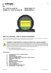
ENGLISH
ENGLISH
A6
INDEX
A
B
C
D
E
F
G
H
I
L
A
Battery Housing
The k24 is powered by two standard type 1.5 V batteries (size AAA).
The battery housing, easily accessible, is closed by a metal cover sealed through a
rubber protection acting as a gasket as well. The whole unit can be easily removed
by unscrewing the 4 screws fixing the cover and the protection to the body.
BECOMING ACQUAINTED WITH K24
A1
Measurement System
A2
Display Positioning
A3
Operating modes
A4
LCD display
A5
User Buttons
A6
Battery Housing
INSTALLATION
DAILY USE
C1
Dispensing in Normal mode
C1.1
Partial reset
C1.2
Resetting the Reset Total
C.2
Dispensing with Flow Rate Mode display
C.2.1
Partial reset
CALIBRATION
D1
Definitions
D2
Why Calibrate
D3
Calibration procedure:
D3.1
Display Of Current “K Factor” And Restoring
“Factory K Factor”
D3.2
In-field Calibration
D3.2.1
In-field calibration procedure:
D3.3
Direct modification of K factor
METERS CONFIGURATION
MAINTENANCE
MALFUNCTIONS
TECHNICAL SPECIFICATIONS
DISPOSAL
EXPLODED VIEWS AND OVERALL DIMENSIONS
B
INSTALLATION
!
ATTENTION
At the female inlets, tighten the couplings at a max. torque of 55N/m.
To reset the Partial Register, finish dispensing and wait for the Remote Display
to show a Flow Rate of 0.0 as indicated in the illustration
then quickly press RESET
1
C.2.1
2
Below are the two typical normal operation displays.
One display page shows the partial and reset total registers. The other shows the
partial and general total. Switchover from resettable total to general total display
is automatic and tied to phases and times that are in factory set and cannot be
changed.
1
With body made of inconductive plastic material of light colour,
designed to be used with water / urea solution
2
With body made of conductive plastic material of dark colour
(assessed resistance: 50 ohm), designed to be used with DIESEL FUEL,
WATER and windscreen fluids.T
he card can be rotated with respect to its housing, thus allowing easy display
readings in any position. The card housing, easily accessible, is closed by a plastic
cover sealed through a rubber protection acting as a gasket as well. The whole unit
can be easily removed by unscrewing the 4 screws fixing the card and the cover.
NOTE: 6 digits are available for Totals, plus two icons x 10 / x100. The
increment sequence is the following:
0.0 → 99999.9 → 999999 → 100000 x 10 → 999999 x 10 → 100000 x 100 →
999999 x 100
C1
Turbine measurement system. The turbine is placed inside a hole through the
body of k24, fitted with threaded inlet and outlet. The body of k24 is made of a
plastic material that allows several types of threads with relevant combinations.
K24 has 2 rubber protections, designed to act as gaskets, too, and thus reducing
the number of its components.
The liquids compatible with k24 must be at low viscosity, namely:
- Diesel fuel
- Water
- Water/urea solution
- Kerosene
- Windscreen
- Petrol
Main components:
Dispensing in Normal mode
Normal mode is the standard dispensing. While the
count is made, the partial and resettable total are
displayed at the same time (reset total).
Should one of the keys be accidentally pressed during
dispensing, this will have no effect.
A few seconds after dispensing has ended, on the
lower register, the display switches from resettable
total to general total: the word reset above the word
total disappears, and the reset total is replaced by the
general total.
This situation is called standby and remains stable until
the user operates the k24 again.
LCD Display
C1.1
Reset Button
Partial reset
The partial register can be reset by pressing the reset
key when the meter is in standby, meaning when the
display screen shows the word “TOTAL”.
Cal Button
After pressing the reset key, during reset, the display
screen first of all shows all the lit-up digits and then all
the digits that are not lit up.
At the end of the process, a display page is first of all
shown with the reset partial and the reset total
Display Positioning
The square shape of the k24 body allows the card to be rotated in its housing,
thus ensuring great versatility in positioning.
4
DISPENSING INTO SAMPLE CONTAINER
Without pressing any KEY, start
dispensing into the sample container.
CALIBRATION
D1
Definitions
Calibration factor or “k factor” :
Multiplication factor applied by the system to the electrical pulses received, to
transform these into measured fluid units.
FACTORY K FACTOR:
Factory-set default factor. It is equal to 1,000. This calibration factor ensures
utmost precision in the following operating conditions:
Fluid
diesel fuel
Temperature:
20°c
Flow rate:
10-120 litres/min
Even after any changes have been made by the user, the factory k factor can be
restored by means of a simple procedure.
C1.2
!
ATTENTION
While fixing the K24 card, make sure the battery contact cable is not placed
above the circular housing of the bulb.
Resetting the Reset Total
The reset total resetting operation can only be
performed after resetting the partial register. The reset
total can in fact be reset by pressing the reset key at
length while the display screen shows reset total as on
the following display page:
H
Combination no.
Unit of Measurement of the
Partial Register
1
2
3
4
Litres (L)
Gallons (Gal)
Quarts (Qts)
Pints (Pts)
Register Unit of
Measurement of the Totals
Register
Litres
Gallons
Gallons
Gallons
(L)
(Gal)
(Gal)
(Gal)
To choose between the 4 available combinations:
• wait for K24 to go to Standby,
• press the CAL and RESET keys together. Keep these pressed until the word
“UNIT” appears on the screen together with the unit of measurement set at that
time (in this example Litres / Litres)
• Press the reset key to select the desired combination of unit of measurement,
amongst those shown below.
• Save the new combination by pressing the cal key at length. K24 will pass
through the start cycle and will then be ready to dispense in the set units.
Indicated value
5
6
USER K FACTOR:
Customized calibration factor, meaning modified by calibration.
Real value
SHORT RESET KEY KEYING
K24 is informed that the calibration dispensing operation is
finished.
Make sure dispensing is correctly finished before performing this
operation.
To calibrate the K24, the value indicated by the partial totaliser
(example 9.800) must be forced to the real value marked on the
graduated sample container.
In the bottom left part of the display an arrow appears (upwards
and downwards), THAT SHOWS the direction (increase or
decrease) of the USER K FACTOR value change when the
operations 6 or 7 are performed
SHORT RESET KEY KEYING
Arrow direction changes. The operation can be repeated IF
NECESSARY
!
F
Measurement system
TURBINE
Resolution
(nominal)
Hi Flow
0.010 lit/pulse
Low Flow
0.005 lit/pulse
Flow Rate
(Range)
K24 COL.
BLACK Flowrates:
5 ÷ 120 (Litres/minute) FOR DIESEL
FUEL, WATER,.
K24 COL.
BEIGE Flowrates
5 ÷ 100 (Litres/minute) FOR WATER/
UREA SOLUTION..
Operating pressure
(Max)
Bursting pressure
(Min)
MAINTENANCE
K24 has been designed to require a minimum amount of maintenance.
The only types of maintenance required are the following:
1. Battery change – necessary when the batteries have run down
2. Cleaning of the turbine with washing or mechanically-handling
40 (Bar)
-20 ÷ + 70 (°C)
Storage humidity
95 (% RU)
(Max)
ELECTRONIC TURBINE
METER
10 (Bar) 145 (psi)
Storage temperature (Range)
Operating temperature (Range)
-10 ÷ + 50 (°C)
Flow resistance
0.30 Bar at 100 lit/min.
Viscosity (Range)
2 ÷ 5.35 cSt
Accuracy
±1% after calibration within
10÷90 (litres/min) 2,65÷23,8 (gallons/
min) range
Reproducibility
WARNING
The Resettable Total and Total registers will be automatically changed
to the new unit of measurement. NO new calibration is required after
changing the Unit of Measurement.
K24
TECHNICAL SPECIFICATIONS
(Typical)
Screen
±0,3 (%)
Liquid crystals LCD. Featuring:
- 5-figure partial
- 6-figure Reset Total plus x10 / x100
6-figure non reset Total plus x10 / x100
Power Supply
2x1.5 V alkaline batteries size AAA
Battery life
18 ÷ 36 months
Weight
0.25 Kg (included batteries)
Protection
IP65
Calibration procedure:
7
8
K24 permits making quick and precise electronic calibration by changing the
calibration factor (k factor).
There are 2 different ways of calibration:
1. On-site calibration, performed by means of a dispensing operation.
2. Direct calibration, performed by directly changing the k factor.
To enter the calibration phases it is necessary to press and hold down the
“cal” button.
Why enter the calibration phases?
• Display the currently used calibration factor
• Return to factory k factor after a previous calibration with user k factor
• Change the calibration factor using one of the two previously indicated
procedures.
In calibration mode, the partial and total dispensed quantities indicated on
the display screen take on different meanings according to the calibration
procedure phase. During the calibration, the k24 cannot perform any normal
dispensing operations. In calibration mode, the totals are not increased.
!
WARNING
The k24 features a non-volatile memory.
It keeps the calibration and dispensing data stored even after replacing
new batteries or long periods of inactivity.
9
10
SHORT/LONG CAL KEY KEYING
The indicated value changes in the direction indicated by the arrow
- one unit for every short CAL key keying
- continually if the CAL key is kept pressed.
(for the first 5 units slowly and then quickly).
If the desired value is exceeded, repeat the operations from point (6).
LONG RESET KEY KEYING
K24 is informed that the calibration procedure is finished.
Before doing this, make sure the DISPLAYED factor is the
ACTUAL factor.
1
Battery Replacement
K24 is complete with 2 x 1.5 V. alkaline batteries SIZE AAA.
K24 features two low-battery alarm levels:
Indicated value Real value
K24 calculates the new USER K FACTOR. This calculation could
require a few seconds, depending on the correction to be made.
During this operation the arrow disappears but the CAL indication
remains.
If this operation is performed after operation (5), without changing
the indicated value, the USER K FACTOR would be the same as
the FACTORY K FACTOR, thus it is ignored.
NO OPERATION
At the end of the calculation, the new USER K FACTOR is
shown for a few seconds, after which the restart cycle is
repeated to finally achieve standby condition.
ATTENTION: From now on, the indicated factor will become
the calibration factor used by the meter and will continue to
remain such even after a battery change
NO OPERATION
K24 stores the new calibration factor and is ready
for dispensing, applying the newly defined USER K FACTOR.
D3.3
Display Of Current “K Factor” And Restoring “Factory K
Factor”
By pressing the cal key while the appliance is in
standby, the display page appears showing the current
calibration factor used.
If you are using k24 with “factory k factor”, the display
page shown in the diagram will be displayed, with the
word “fact”.
If one “user k factor” has been set, the calibration
factor set by the user (in our example 0.998) will be
displayed. The word “user” indicates a calibration
factor set by the user is being used.
Direct modification of K factor
Example:
Error percentage found E%
CURRENT calibration factor
New USER K FACTOR
(
100 - E%
100
)
- 0.9 %
1,000
1,000 * [(100 – ( - 0,9))/100]=
1,000 * [(100 + 0,9)/100] = 1.009
If the meter indicates less than the real dispensed value (negative error) the new
calibration factor must be higher than the old one as shown in the example. The
opposite applies if the meter shows more than the real dispensed value (positive
error).
DISPOSAL
1) When the battery charge falls below the first level on
the LCD, the fixed battery symbol appears.
The components must be given to companies that specialise in the disposal
and recycling of industrial waste and, in particular, the
In this condition, K24 continues to operate correctly,
but the fixed icon warns the user that it is ADVISABLE
to change the batteries.
DISPOSAL OF PACKAGING.
The packaging consists of biodegradable cardboard which can be delivered to
companies for normal recycling of cellulose.
2) If K24 operation continues without changing the
batteries, the second battery alarm level will be
reached which will prevent operation. In this condition
the battery icon starts to flash and is the only one to
remain visible on the LCD.
DISPOSAL OF METAL COMPONENTS
The metal components, both painted and stainless steel, are usually recycled
by companies that are specialised in the metal-scrapping industry.
!
DISPOSAL OF ELECTRIC AND ELECTRONIC COMPONENTS:
these have to be disposed by companies that are specialised in the disposal
of electronic components, in accordance with the instructions of 2002/96/EC
(see text of Directive below).
To change the batteries, with reference to the exploded diagram positions,
proceed as follows:
• Press RESET to update all the totals
• Loosen the 4 fixing screws of the lower cover
• Remove the old batteries
• Place the new batteries in the same position as the old ones
• close the cover again, by positioning the rubber protection as a gasket
• K24 will switch on automatically and normal operation can be resumed.
ENVIRONMENTAL INFORMATION FOR CUSTOMERS IN THE EUROPEAN
UNION
European Directive 2002/96/EC requires that the equipement
bearing this symbol on the product and/or its packaging must
not be disposed of with unsorted municipal waste. The symbol
indicates that this product should be disposed of separately
from regular household waste streams. It is your responsibility
to dispose of this and other electric and electronic equipment via
designated collection facilities appointed by the government or
local authorities.
WARNING
Do not discard the old batteries in the environment. Refer to local
disposal regulations.
This procedure is especially useful to correct a “mean error” obtainable on the basis
of several performed dispensing operations. If normal K24 operation shows a mean
percentage error, this can be corrected by applying to the currently used calibration
factor a correction of the same percentage. In this case, the percentage correction
of the USER K FACTOR must be calculated by the operator in the following way:
New K Factor = Old K Factor *
I
The K24 will display the same Reset Total, the same Total and the same
Partial indicated before the batteries were changed.
After changing the batteries, the meter does not need calibrating again.
DISPOSAL OF OTHER PARTS:
The disposal of other parts such as pipes, rubber seals, plastic components
and cables should be entrusted to companies that special in the disposal of
industrial waste.
2.
Cleaning
Only one operation is necessary to clean the k24.
AAfter removing k24 from the plant where it was built in, any residual elements
can be removed by washing or mechanically-handling.
If this operation does not restore a smooth rotation of the turbine, it will have
to be replaced.
!
WARNING:
Do not use compressed air onto the turbine in order to avoid its damage
because of an excessive rotation
Schematically, the steps to be taken are:
A3
Operating modes
The user can choose between two different operating modes:
- Normal Mode: Mode with display of Partial and Total dispensed quantities.
- Flow Rate Mode: Mode with display of Flow Rate, as well as Partial dispensed
quantity.
The meter features a non-volatile memory for storing the dispensing data, even
in the event of a complete power break for long periods.
The measurement electronics and the LCD display are fitted in the top part of
the K24 which remains isolated from the fluid-bath measurement chamber and
sealed from the outside by means of a cover.
A4
LCD display
The “LCD” of the METER
features two numerical registers
and
various
indications
displayed to the user only
when the applicable function so
requires.
1
9
2
8
Key:
7
1.
Partial register (5 3
figures with moving comma
FROM 0.1 to 99999) indicating
4
5 6
the volume dispensed since the
reset button was last pressed;
2.
Indication of battery charge;
3.
Indication of calibration mode;
4.
Totals register (6 figures with moving comma FROM 0.1 to 999999),
that can indicate two types of Total:
4.1.
General Total that cannot be reset (TOTAL)
4.2.
Resettable total (Reset TOTAL)
5.
Indication of total multiplication factor (x10 / x100 )
6.
Indication of type of total, (TOTAL / Reset TOTAL);
7.
Indication of unit of measurement of Totals: L=Litres Gal=Gallons
8.
Indication of Flow Rate mode
9.
Indication of unit of measurement of Partial: Qts=Quarts
Pts=Pints
L=Litres
Gal=Gallons
A5
User Buttons
The k24 features two buttons (reset and cal) which individually perform two main
functions and, together, other secondary functions.
The main functions performed are:
For the reset key, resetting the partial register and resettable total
(reset total)
For the cal key, entering instrument calibration mode.
Used together, the two keys permit entering configuration mode, useful for
changing the units of measurements and calibration factor.
1. Wait for the display to show normal standby display
page (with total only displayed),
2. Press the reset key quickly
3. The meter starts to reset the partial
4. While the display page showing the reset total is
displayed
Press the reset key again for at least 1 second
5. The display screen again shows all the segments of
the display followed by all the switched-off segments and
finally shows the display page where the reset Reset
Total is shown.
C.2
Dispensing with Flow Rate Mode display
It is possible to dispense fluids, displaying at the same time:
*
the dispensed partial
*
the Flow Rate in [Partial Unit / minute]
as shown on the following display page:
The flow chart alongside
shows the switchover logic
from one display page to
another.
In this condition, the Reset
key permits switching from
User factor to Factory
factor.
To confirm the choice of
calibration factor, quickly
press CAL while “User” or
“Fact” are displayed.
After the restart cycle, the
meter uses the calibration
factor that has just been
confirmed.
!
ATTENTION
When the Factory Factor
is confirmed, the old User
factor is deleted from the
memory
D3.2
Procedure for entering this mode:
- wait for the Remote Display to go to Standby, meaning the display screen
shows Total only
- quickly press the CAL key.
- Start dispensing
The flow rate is updated every 0.7 seconds. Consequently, the display could be
relatively unstable at lower flow rates. The higher the flow rate, the more stable
the displayed value.
!
IMPORTANT
The flow rate is measured with reference to the unit of measurement of the
Partial. For this reason, in case of the unit of measurement of the Partial
and Total being different, as in the example shown below, it should be
remembered that the indicated flow rate relates to the unit of measurement
OPERATION
1
NONE
K24 in STAND BY: not in counting mode.
!
WARNING
For correct K24 calibration, it is most important to:
• completely eliminate air from the system before calibrating;
• use a precise Sample Container with a capacity of not less than 5 litres,
featuring an accurate graduated indicator.
• ensure calibration dispensing is done at a constant flow rate equivalent
to that of normal use, until the container is full;
•not reduce the flow rate to reach the graduated area of the container
during the final dispensing stage (the correct method during the final
stages of sample container filling consists in making short top-ups at
normal operation flow rate) ;
• after dispensing, wait a few minutes to make sure any air bubbles are
eliminated from the sample container; only read the Real value at the end
of this stage, during which the level in the container could drop.
• if necessary, carefully follow the procedure indicated below.
G.
DECLARATION OF CONFORMITY
MALFUNCTIONS
Problem
Possible Cause
LCD: no indication Bad battery contact
2
3
4
5
LONG CAL KEY KEYING
K24 enters calibration mode, shows “CAL” and displays the
calibration factor being used instead of the partial. The words
“Fact” and “USER” indicate which of the two factors (factory or
user) is currently being used.
LONG RESET KEY KEYING
K24 shows “CAL” and the partial at zero.
K24 is ready to perform on-site calibration by dispensing.
LONG RESET KEY KEYING
We now go on to Direct change of the calibration factor:
the word “Direct” appears together with the Currently Used
calibration factor. In the bottom left part of the display, an
arrow appears (upwards or downwards) defining the direction
(increase or decrease) of change of the displayed value when
subsequent operations 5 or 6 are performed.
SHORT RESET KEY KEYING
Arrow direction changes. The operation can be repeated to
alternate the direction of the arrow.
In-field Calibration
This procedure calls for the fluid to be dispensed into a graduated sample
container in real operating conditions (flow rate, viscosity, etc.) requiring
maximum precision.
DISPLAY
6
SHORT/LONG CAL KEY KEYING
The indicated value changes in the direction indicated by the arrow
one unit for every short CAL key keying
continually if the CAL key is kept pressed. The speed
increase rises by keeping the key pressed. If the desired value is
exceeded, repeat the operations from point (5).
7
LONG RESET KEY KEYING
K24 is informed that the calibration procedure is finished.
Before performing this operation, make sure the indicated
value is that required.
8
NO OPERATION
At the end of the calculation, the new USER K FACTOR is
shown for a few seconds, after which the restart cycle is
repeated to finally achieve standby condition.
ATTENTION: From now on, the indicated factor will
become the calibration factor used by the meter and will
continue to remain such even after a battery change.
NO OPERATION
The K24 stores the new work calibration factor and is ready
to begin dispensing, using the USER K FACTOR that has just
been calculated.
9
Not enough
measurement
precision
Reduced or zero
flow rate
The meter does
not count,
but the flow rate is
correct
Azione Correttiva
Check battery contacts
With reference to
paragraph H, check the K
FACTOR
Wrong K FACTOR
The meter works below
Increase the flow rate until
minimum acceptable flow an acceptable flow rate
rate.
range has been achieved
TURBINE blocked
Clean the TURBINE
Incorrect installation of
gears after cleaning
Repeat the
procedure
Possible electronic
problems
card
reassembly
The undersigned, representing the following manufacturer
Piusi S.p.A.
46029 – Suzzara (Mantova) - Italy
CERTIFIES
that the equipment described below:
K24
complies with the following directives:
2004/108/CE (Electromagnetic Compatibility Directive)
and following amendments
Contact your dealer
Suzzara 01.07.2009
MANUALE D’USO, MANUTENZIONE
E CALIBRAZUIONE
Italiano
USE, MAINTENANCE AND
CALIBRATION MANUAL
English
Bulletin
Why Calibrate
When operating close to extreme conditions, such as for instance with fluids
close to acceptable range extremes (like diesel fuel at low temperatures) or
in extreme flow rate conditions (close to minimum or maximum acceptable
values), an on-site calibration may be required to suit the real conditions in
which the k24 is required to operate.
D3
METERS CONFIGURATION
Some models of meter feature a menu with which the user can select the main
measurement unit, Quarts (Qts), Pints (Pts), Litres (Lit), Gallons (Gal);
The combination of the unit of measurement of the Partial register and that of the
Totals is predefined according to the following table:
LONG CAL KEY KEYING
K24 enters calibration mode, shows ”CAL” and displays the
calibration factor in use instead of total. The words “Fact” and
“USER” indicate which of the two factors is currently in use.
3 LONG RESET KEY KEYING
K24 shows “CAL” and the partial at zero. K24 is ready to perform
on-site calibration.
Partial reset
D
D3.1
and, after a few moments, the reset total is replaced by
the non resettableTotal.
NONE
K24 IN STAND BY
Dispensing can be interrupted and started again at will. Continue
dispensing until the level of the fluid in the sample container has
reached the graduated area. There is no need to reach a preset
quantity.
D2
Measurement System
E
DISPLAY
3
DAILY USE
The only operations that need to be done for daily use are partial and/or resettable
total register resetting.
The user should use only the dispensing system of k24.
Occasionally the meter may need to be configured or calibrated. To do so, please
refer to the relevant chapters.
In-field calibration procedure:
To return to “Normal” mode, press the CAL key again. If one of the two keys
RESET or CAL is accidentally pressed during the count, this will have no effect.
IMPORTANT
Even though in this mode they are not displayed, both the Reset Total
and the General Total (Total) increase. Their value can be checked after
dispensing has terminated, returning to “Normal” mode, by quickly
pressing CAL.
C
Electronic digital meter featuring a turbine measurement system, designed for
precise measuring of low viscosity fluids.
It is divided into two using macrogroups:
A2
D3.2.1
ENGLISH
ENGLISH
AZIONE
ATTENTION:
ITH THE GAS-FEMALE INLETS, DO NOT USE CONICAL THREADED
COUPLINGS.
BECOMING ACQUAINTED WITH K24
A1
of the partial. In the example shown, the flow rate is expressed in Qts/min.
The word “Gal” remaining alongside the flow rate refers to the register of
the Totals (Reset or NON Reset) which are again displayed when exiting
from the flow rate reading mode.
K24 features a threaded, perpendicular inlet and outlet (1” gas or ntp male
and female that can be combined together). It has been designed to be easily
installed in any position: fixed in-line or mobile on a dispensing nozzle.
In order to improve the life of the turbine, it is recommended to fit a strainer
before the meter itself
!
!
ENGLISH
ENGLISH
President
M0171AITEN rev. 3
INDICE
A
CONOSCERE K24
A1
Sistema Di Misura
A2
Orientamento Display
A3
Modalità di utilizzo
A4
Display LCD
A5
Pulsanti Utente
A6
Sede Batterie
INSTALLAZIONE
USO GIORNALIERO
C1
erogazione in modalità normale (normal mode)
C1.1
Azzeramento del Parziale
C1.2
Azzeramento del Reset Total (Totale Azzerabile)
C.2
Erogazione con visualizzazione Portata Istantanea
(Flow Rate Mode)
C.2.1
Azzeramento del Parziale
CALIBRAZIONE
D1
DEFINIZIONI
D2
PERCHÉ CALIBRARE
D3
Modalità di Calibrazione
D3.1
visualizzazione “K factor” attuale e ripristino
del “factory k factor”.
D3.2
Calibrazione In Campo
D3.2.1
Procedura per effettuare la
Calibrazione in Campo:
D3.3
Modifica diretta del K factor
CONFIGURAZIONE DEI CONTALITRI
MANUTENZIONE
MALFUNZIONAMENTI
DATI TECNICI
SMALTIMENTO
VISTE ESPLOSE ED INGOMBRI
B
C
D
E
F
G
H
I
L
A
CONOSCERE K24
Contalitri elettronico digitale provvisto di un sistema di misura a turbina, progettato
per una precisa misurazione di fluidi a bassa viscosita’.
Si divide in 2 macro famiglie di utilizzo:
1 - Con corpo realizzato in materiale plastico non conduttivo di colore chiaro, ideato
per l’utilizzo con soluzione di acqua/urea
2 - Con corpo realizzato in materiale plastico conduttivo di colore scuro (resistenza
accertata: 50 ohm) e ideato per l’utilizzo con GASOLIO, ACQUA e windscreen.
La scheda puo’ essere ruotata rispetto alla sua sede. Questo consente una
facile lettura del display in tutte le posizioni. La sede della scheda, facilmente
accessibile, è chiusa da un coperchio in plastica con tenuta garantita dalla
protezione in gomma che funge anche da guarnizione. Il tutto e’ facilmente
rimuovibile svitando le 4 viti che fissano coperchio e scheda.
A1
Sistema Di Misura
Sistema di misura a turbina. La turbina è posizionata all’interno di un foro che attraversa il
corpo del k24 e dotato di ingresso ed uscita filettati. I materiale plastico di cui è costrituito
il corpo di k24, permette varie filettature e relative numerose combinazioni.
K24 e’ corredato da 2 protezioni in gomma, progettate in modo da fungere anche da
guarnizioni, riducendo cosi’ il numero di particolari che lo compongono.
I liquidi compatibili con il k24 devono essere a bassa viscosità e precisamente i seguenti:
- Gasolio
- Acqua
- Soluzone acqua/urea
- Kerosene
- Windscreen
- Benzina
Componenti Principali:
Display LCD
Tasto Reset
A6
Sede Batterie
K24 è alimentato da due batterie di tipo standard da 1,5 v (size AAA).
La sede delle batterie, facilmente accessibile, è chiusa da un coperchio metallico
con tenuta garantita dalla protezione in gomma che funge anche da guarnizione.
Il tutto e’ facilmente rimuovibile svitando le 4 viti che fissano coperchio e
protezione al corpo.
B
INSTALLAZIONE
K24 ha ingresso e uscita filettati (1” gas o npt maschio e femmina, combinabili
tra loro) ed in asse. E’ studiato per essere facilmente installato in qualsiasi
posizione: fisso su una linea o mobile su una pistola di erogazione. Prevedere
sempre la presenza di un disco filtrante a monte dell’impianto, al fine di
garantire maggiore durata della turbina.
!
!
ATTENZIONE:
Sugli ingressi femmina, serrare i raccordi di giunzione ad una coppia
massima di 55N/m
ATTENZIONE:
SUGLI INGRESSI FEMMINA GAS, NON UTILIZZARE RACCORDI
CON FILETTI CONICI
C
Nota: i digit disponibili per i totali sono 6 a cui si aggiungono due icone
x 10 / x100.La sequenza di incremento è la seguente: 0.0 → 99999.9 →
999999 → 100000 X 10 → 999999 x 10 → 100000 x 100 → 999999 x 100
C1
erogazione in modalità normale (normal mode)
Normal mode è l’erogazione standard. Durante il
conteggio, vengono visualizzati contemporaneamente il
“parziale erogato” ed il “totale azzerabile” (reset total).
Premere accidentalmente i tasti durante l’erogazione,
non comporta alcun effetto
Ad alcuni secondi dal termine dell’erogazione, sul
registro inferiore la visualizzazione passa dal “totale
azzerabile” al ”totale generale”: la scritta reset posta
sopra alla scritta total scompare, ed il valore del “totale
azzerabile”, viene sostituito dal “totale generale”.
Questa situazione viene definita di riposo (o STANDBY) e rimane stabile fino a quando l’utente non effettua
altre operazioni sul K24
Azzeramento del Parziale
Il Registro del Parziale può essere azzerato premendo
il tasto RESET quando il meter è in Stand-by, ovvero
quando il display visualizza la scritta «TOTAL».
Dopo la pressione del tasto RESET, durante la fase di
azzeramento, il display mostra in successione prima tutti
i digit accesi, poi tutti i digit spenti.
A2
!
ATTENZIONE:
In fase di fissaggio scheda del K24, è importante fare attenzione che il cavo
del contatto pile non si posizioni sopra la sede circolare dell’ampolla.
Modalità di utilizzo
L’utente può scegliere tra due modalità diverse di utilizzo:
- Normal mode: modalità con visualizzazione delle quantità parziali e totali erogate
- Flow rate mode: modalità con visualizzazione della portata istantanea (flow
rate), oltre che del parziale erogato
Il meter è provvisto di una memoria non volatile che permette di mantenere i
dati archiviati delle erogazioni eseguite anche in caso di completa assenza di
alimentazione per lunghi periodi. L’elettronica di misura e il display a cristalli liquidi
«lcd» sono installati nella parte superiore del k24. Che resta cosi’ isolata dalla
camera di misura bagnata dal fluido e sigillata dall’esterno tramite un coperchio.
Display LCD
L’ «LCD» del meter è provvisto di due registri numerici e di diverse indicazioni che
vengono visualizzate dall’utente solamente se la funzione del momento lo richiede
Legenda:
1.
Registro del parziale (5 cifre a virgola mobile da 0.1 A 99999), che indica
il volume erogato dall’ultima volta che è stato premuto il pulsante di reset;
2.
Indicazione
dello
stato di carica delle batterie;
3.
Indicazione
della 1
9
modalità di calibrazione;
4.
Registro dei totali (6
cifre a virgola mobile da 0,1 a 2
8
999999),
7
che può indicare 3
due tipi di totale:
4.1.
To t a l e
4
5 6
generale
non azzerabile
(total)
4.2.
Totale azzerabile (reset total)
5.
Indicazione del fattore di moltiplicazione dei totali (x10 / x100)
6.
Indicazione del tipo di totale, (total / reset total);
7.
Indicazione dell’unità di misura dei totali:
l=litri gal=galloni
8.
Indicazione della modalità “Portata Istantanea” (Flow Rate)
9.
Indicazione dell’unità di misura del parziale: qts=quarti;
pts=pinte;
l=litri;
gal=galloni
A5
Per tornare nella modalità “Normale” premere nuovamente il tasto CAL. La
pressione accidentale di uno dei due tasti RESET o CAL durante il conteggio
non ha alcun effetto.
!
ATTENZIONE:
Anche se in questa modalità non vengono visualizzati, sia il totale azzerabile (Reset
Total) che il Totale Generale (Total) si incrementano. E’ possibile controllare il loro
valore dopo la fine dell’erogazione, tornando nella modalità “Normale”, premendo
brevemente il tasto CAL.
C.2.1
Pulsanti Utente
K24 è dotato di due pulsanti (reset e cal) che svolgono, singolarmente, due
funzioni principali e, in combinazione, altre funzioni secondarie.
Le funzioni principali svolte sono:
- Per il tasto reset, l’azzeramento del registro del parziale e di quello del totale
azzerabile (reset total)
- Per il tasto cal, l’entrata nella modalità di calibrazione dello strumento
Utilizzati in combinazione, i due tasti consentono di entrare in modalità di
configurazione (configuration mode), utile per modifiche sull’unita’di misura e
sul fattore di calibrazione.
AZIONE
1
2
3
Azzeramento del Parziale
Per azzerare il Registro del Parziale occorre terminare l’erogazione, attendere
che il Display Remoto indichi un Flow Rate di 0.0 come indicato in figura
e poi premere brevemente il tasto RESET.
Alla fine del processo viene mostrata dapprima una
schermata che presenta il Parziale azzerato e il Reset
Total
C1.2
Azzeramento del Reset Total (Totale Azzerabile)
L’operazione di azzeramento del Reset Total è
effettuabile solo successivamente ad una operazione
di azzeramento del registro del Parziale. Infatti il Reset
Total può essere azzerato premendo a lungo il tasto
RESET mentre il display visualizza la scritta RESET
TOTAL come nella schermata seguente:
Schematicamente i passi da seguire sono:
1. Attendere che il display sia nella schermata normale
di stand-by (con il solo Total visualizzato),
2. Premere brevemente il tasto RESET
3. Il meter inizia le sue fasi di azzeramento del
Parziale.
4. Mentre è visualizzata la schermata che indica il Reset
Total
premere nuovamente il tasto Reset per un tempo di
almeno 1 secondo
5. Il display torna nuovamente a mostrare tutti i segmenti
del display seguito dalla fase con tutti e segmenti spenti
per giungere alla schermata in cui viene visualizzato il
Reset Total azzerato.
C.2
Erogazione con visualizzazione Portata Istantanea
(Flow Rate Mode)
E’ possibile effettuare erogazioni visualizzando contemporaneamente:
•
il parziale erogato
•
la Portata Istantanea (Flow Rate) in [Unità del Parziale /minuto]
come indicato nella schermata seguente:
Procedura per entrare in questa modalità:
• attendere che il Display Remoto sia in Stand-By, ovvero che il display visualizzi il
solo Total
• premere brevemente il tasto CAL.
• Iniziare l’erogazione
La portata istantanea viene aggiornata ogni 0,7 secondi. Pertanto alle portate
più basse si potrà avere una visualizzazione relativamente instabile. Più è alta la
portata maggiore sarà la stabilità del valore letto.
!
ATTENZIONE:
La portata viene misurata con riferimento all’unità di misura del Parziale.
Per questo motivo, qualora l’unità di misura del Parziale e del Totale
fossero diverse, come nell’esempio sotto riportato, occorre ricordare che
la portata indicata è relativa alla unità di misura del parziale. Nell’esempio
E
D3.2.1 Procedura per effettuare la Calibrazione in Campo
4
NESSUNA
K24 in stand by
BATTITURA LUNGA DEL TASTO CAL
K24 entra nella modalità di calibrazione, mostra l’indicazione di
“CAL” e visualizza il fattore di calibrazione in uso al posto del
totale cumulativo. Le scritte “Fact” e “USER” stanno ad indicare
quale dei due fattori è attualmente in uso.
BATTITURA LUNGA DEL TASTO RESET
K24 mostra l’indicazione di “CAL” e il totale parziale a zero. K24
è pronto ad eseguire la calibrazione in campo.
D
CALIBRAZIONE
D1
DEFINIZIONI
FATTORE DI CALIBRAZIONE O “K FACTOR”:
Fattore moltiplicativo che il sistema applica agli impulsi elettrici ricevuti, per
trasformarli in unità di fluido misurato
FACTORY K FACTOR:
Fattore di calibrazione impostato di default in fabbrica. E’ uguale a 1,000. Tale
fattore di calibrazione garantisce la massima precisione nelle seguenti condizioni
di utilizzo:
Fluido
GASOLIO
Temperatura:
20°C
Portata:
10 - 120 litri/min
Anche dopo eventuali modifiche da parte dell’utente, attraverso una semplice
procedura, è possibile ripristinare il fattore di calibrazione di fabbrica.
USER K FACTOR:
Fattore di calibrazione personalizzato dall’utente, ovvero modificato da una
calibrazione.
D2
PERCHÉ CALIBRARE
5
6
D3
Modalità di Calibrazione
7
8
Esistono 2 diversi metodi di calibrazione:
1. Calibrazione in campo, eseguita attraverso una erogazione
2. Calibrazione diretta, eseguita attraverso una modifica diretta del k factor.
Per entrare nelle fasi di calibrazione è necessario premere a lungo il tasto “cal”.
Perche’ entrare nelle fasi di calibrazione?
• Visualizzare il fattore di calibrazione attualmente utilizzato
• Tornare al fattore di calibrazione di fabbrica (factory k factor) dopo una
precedente calibrazione con user k factor
• Modificare il fattore di calibrazione attraverso una delle due procedure indicate
precedentemente
In modalità di calibrazione le indicazioni di parziale erogato e cumulativo
presenti sul display, assumono significati diversi in base alla fase della procedura
di calibrazione. Durante la calibrazione, il k24 non può effettuare normali
erogazioni. In modalità di calibrazione i totali non vengono incrementati.
!
9
ATTENZIONE
K24 è provvisto di memoria non volatile.
Questa mantiene in memoria dati di calibrazione e di erogazione anche dopo la
sostituzione delle batterie o lunghi periodi di inutilizzo.
D3.1
VISUALIZZAZIONE “K FACTOR” ATTUALE E RIPRISTINO
DEL “FACTORY K FACTOR”.
Premendo a lungo il tasto cal mentre l’apparecchio è
in stand-by, si giunge alla schermata che mostra il
fattore di calibrazione attualmente utilizzato. Se si sta
utilizzando k24 con il “factory k factor”, verra’ mostrata
la schermata rappresentata nello schema, con la
scritta “fact”.
Se è invece stato impostato un “user k factor”, verra’
visualizzato il fattore di calibrazione impostato dall’utente
(nel nostro esempio 0.998). La scritta “user” dà evidenza
del fatto che si sta utilizzando il fattore di calibrazione
impostato dall’utente.
Il diagramma di flusso
riportato a fianco riporta la
logica di passaggio tra le
varie schermate.
In questa condizione, il tasto
reset consente di passare
dal fattore user al factory.
Per confermare la scelta
del fattore di calibrazione,
premere cal brevemente
mentre è visualizzato lo “user”
o il “fact”.
Dopo il ciclo di riavvio il
contalitri utilizzerà il fattore
di
calibrazione
appena
confermato
!
D3.2
Calibrazione In Campo
EROGAZIONE NEL RECIPIENTE CAMPIONE
Senza premere nessun TASTO, cominciare
l’erogazione nel recipiente campione.
Litri (Lit)
Galloni (Gal)
Galloni (Gal)
Galloni (Gal)
ATTENZIONE
I registri Resettable Total e Total vengono automaticamente convertiti
nella nuova unità di misura. La modifica dell’Unità di Misura NON rende
necessario effettuare una nuova calibrazione.
F
MANUTENZIONE
Le uniche manutenzioni richieste sono:
1. Sostituzione batterie, richiesta quando sono scariche
2. Pulizia della turbina tramite lavaggio con liquido o azione meccanica,
eventualmente necessaria per favorirne la rotazione.
1
Sostituzione batterie
K24 è fornito di 2 batterie alcaline size AAA 1,5 volt.
K24 è provvisto di due livelli di allarme di batteria scarica:
1) Quando la carica di batteria scende sotto al primo
livello sull’lcd compare il simbolo di batteria fisso.
In questa condizione K24 continua a funzionare
correttamente, ma l’icona fissa avverte l’utente che è
CONSIGLIABILE sostituire le batterie.
2) Se si continua ad utilizzare K24 senza sostituire le
batterie, si giungerà al secondo livello di allarme batteria
che inibisce il funzionamento. In questa condizione
l’icona di batteria diventa lampeggiante e rimane l’unica
visibile sull’LCD
Valore indicato Valore Reale
K24 calcola il nuovo USER K FACTOR. Questo calcolo può
richiedere alcuni secondi, in ragione della correzione che deve
essere eseguita.
Durante questa fase la freccia scompare ma l’indicazione CAL
rimane.
Se questa operazione è eseguita dopo l’azione (5), senza
cambiare il valore indicato, lo USER K FACTOR risulterebbe
uguale al FACTORY K FACTOR, quindi viene ignorato.
NESSUNA AZIONE
Alla fine del calcolo il nuovo USER K FACTOR è mostrato per
alcuni secondi dopodiché si ripete il ciclo di riavvio per giungere
infine alla condizione di stand-by.
ATTENZIONE: Da questo momento, quello indicato diventerà
il fattore di calibrazione utilizzato dal meter e rimarrà tale
anche dopo una eventuale sostituzione delle batterie
NESSUNA AZIONE
K24 memorizza il nuovo fattore di calibrazione di lavoro ed è
pronto
per l’erogazione, utilizzando lo USER K FACTOR appena
calcolato.
!
ATTENZIONE
Non gettare le batterie scariche nell’ambiente. Fare riferimento ai
regolamenti locali per lo smaltimento.
Per sostituire le batterie , con riferimento alle posizioni del disegno esploso,
procedere nel seguente modo:
• Premere reset per aggiornare tutti i totali
• Svitare le 4 viti di fissaggio del coperchio inferiore.
• Rimuovere le batterie esaurite
• Mettere le nuove batterie nella posizione delle precedenti
• Richiudere il coperchio, riposizionando la protezione in gomma a modi di guarnizione.
• K24 si accenderà automaticamente e si potrà riprendere il normale utilizzo.
(
100 - E%
100
)
Esempio:
Percentuale di errore riscontrata E%
Fattore di calibrazione ATTUALE
Nuovo USER K FACTOR
- 0.9 %
1,000
1,000 * [(100 – ( - 0,9))/100]=
1,000 * [(100 + 0,9)/100] = 1.009
Se il contalitri indica meno del reale valore erogato (errore negativo) il nuovo fattore
di calibrazione deve essere maggiore del vecchio come mostrato dall’esempio.
Viceversa se il contalitri indica più del reale valore erogato (errore positivo).
K24 visualizzerà lo stesso resettable total, lo stesso total e lo stesso parziale
indicati prima della sostituzione delle batterie. Dopo la sostituzione batterie, non
è necessaria alcuna ri-calibrazione del contalitri.
!
ATTENZIONE:
Non utilizzare aria compressa sulla turbina per evitarne il danneggiamento
a causa di una eccessiva rotazione.
DISPLAY
Possibile Causa
NESSUNA
Display Remoto in modo normale, non in conteggio.
2
BATTITURA LUNGA DEL TASTO CAL
Display Remoto entra nella modalità di calibrazione, e viene
visualizzato il fattore di calibrazione in uso al posto del parziale. Le
scritte “Fact” o “USER” stanno ad indicare quale dei due fattori (di
lavoro o di fabbrica) è attualmente in uso.
Precisione di
misura insufficiente
BATTITURA LUNGA DEL TASTO RESET
Il Display Remoto mostra l’indicazione di “CAL” e il totale parziale a
zero.
Display Remoto è pronto ad eseguire la calibrazione in campo tramite
erogazione.
Portata ridotta o nulla TURBINA bloccata
5
6
7
8
9
BATTITURA LUNGA DEL TASTO RESET
Si passa alla modifica Diretta del fattore di calibrazione:
compare la scritta “Direct” e il fattore di calibrazione Attualmente
in Uso. Nella parte in basso a sinistra del display appare una
freccia (verso l’alto o verso il basso) che definisce la direzione
(aumento o diminuzione) di variazione del valore visualizzato
quando vengono effettuate le successive azioni 5 o 6.
BATTITURA CORTA DEL TASTO RESET
Cambia direzione la freccia. L’azione può essere ripetuta per
alternare il senso della freccia.
Portata
(Campo)
TURBINA
Alte Portate
0.010 litri/impulso
Basse Portate
0.005 litri/impulso
K24 COL. NERO
Portate
5 ÷ 120 (Litri/minuto) PER GASOLIO,
ACQUA, LIQUIDO LAVAVETRI.
K24 COL. BEIGE
Portate
5 ÷ 100 (Litri/minuto) PER
SOLUZIONE ACQUA/UREA.
Pressione di esercizio (Max)
10 (Bar)
Pressione di scoppio (Min)
40 (Bar)
Temperatura di stoccaggio (Campo)
-20 ÷ + 70 (°C)
Umidità di stoccaggio (Max)
95 (% RU)
1
2
Temperatura di esercizio (Campo)
-10 ÷ + 50 (°C)
Perdita di carico
0.30 Bar a 100 lit/min.
Viscosità (Campo)
2 ÷ 5.35 cSt
Precisione (tra 10 e 90 l/min)
±1 del valore
calibrazione (%)
Ripetibilità
(Tipica)
±0,3
(%)
Schermo
A cristalli liquidi LCD Provvisto di:
-Parziale a 5 cifre
Totale azzerabile a 6 cifre più x10 /
x100
- Totale NON azzerabile a 6 cifre più
x10 / x100
indicato
Alimentazione
Batterie alcaline 2x1,5V size AAA
Durata batteria
18 ÷ 36 mesi
Peso
0.25 Kg (batterie incluse)
Grado di Impermeabilità
IP65
I
SMALTIMENTO
In caso di demolizione, le parti di cui è composto devono essere affidate a ditte
specializzate nello smaltimento e riciclaggio dei rifiuti industriali e, in particolare:
SMALTIMENTO DELL’IMBALLAGGIO:
L’imballaggio è costituito da cartone biodegradabile che può essere
consegnato alle aziende per il normale recupero della cellulosa.
SMALTIMENTO DELLE PARTI METALLICHE:
Le parti metalliche, sia quelle verniciate, sia quelle in acciaio inox sono
normalmente recuperabili dalle aziende specializzate nel settore della
rottamazione dei metalli.
SMALTIMENTO DEI COMPONENTI ELETTRICI ED ELETTRONICI:
devono obbligatoriamente essere smaltite da aziende specializzate nello
smaltimento dei componenti elettronici, in conformità alle indicazioni della
direttiva 2002/96/CE (vedi testo direttiva nel seguito).
INFORMAZIONI RELATIVE ALL’AMBIENTE PER I CLIENTI RESIDENTI
NELL’UNIONE EUROPEA
La direttiva Europea 2002/96/EC richiede che le apparecchiature
contrassegnate con questo simbolo sul prodotto e/o
sull’imballaggio non siano smaltite insieme ai rifiuti urbani non
differenziati. Il simbolo indica che questo prodotto non deve essere
smaltito insieme ai normali rifiuti domestici. E’ responsabilità del
proprietario smaltire sia questi prodotti sia le altre apparecchiature
elettriche ed elettroniche mediante le specifiche strutture di
raccolta indicate dal governo o dagli enti pubblici locali.
SMALTIMENTO DI ULTERIORI PARTI:
Ulteriori parti, come tubi, guarnizioni in gomma, parti in plastica e cablaggi,
sono da affidare a ditte specializzate nello smaltimento dei rifiuti industriali.
L
3
dopo
4
DICHIARAZIONE DI CONFORMITA’
Il sottoscritto, rappresentante il seguente costruttore
Piusi S.p.A.
46029 – Suzzara (Mantova) - Italia
DICHIARA
che l’apparecchiatura descritta in appresso:
K24
E’ conforme alle seguenti direttive:
2004/108/CE (Direttiva compatibilità elettromagnetica) e successive modifiche
Suzzara 01.07.2009
Il Presidente
EXPLODED VIEWS AND OVERALL DIMENSIONS
/VISTE ESPLOSE ED INGOMBRI /
75
1" G
1" NPT
54
M-M
1" G
1" NPT
MALFUNZIONAMENTI
Problema
1
4
Risoluzione
2.
Pulizia
La pulizia del k24, si riduce ad una unica operazione.
Infatti, dopo aver separato il k24 dall’impianto in cui è stato incorporato, si potranno
rimuovere eventuali residui, utilizzando liquido o con l’ausilio di azione meccanica.
Se tale pulizia non riesce a ripristinare una fluida rotazione della turbina, sara’
necessaria la sua sostituzione.
G.
AZIONE
DATI TECNICI
Sistema di misura
!
BATTITURA CORTA/LUNGA DEL TASTO CAL
Il valore indicato cambia nella direzione definita dalla freccia
- una unità per ogni battitura breve del tasto CAL
- continuamente se il tasto CAL è mantenuto premuto.
(per le prime 5 unità con andamento lento, poi con un andamento
veloce).
Se si sorpassa il valore desiderato , ripetere le azioni dal punto
(6).
BATTITURA LUNGA DEL TASTO RESET
K24 VIENE COSI’ informato che la procedura di calibrazione è
finita.
Prima di effettuare questa operazione, fare attenzione che il
valore INDICATO
sia uguale al valore REALE.
Nuovo fattore di calibrazione = Vecchio fattore di calibrazione *
ATTENZIONE:
Per ottenere una corretta calibrazione del k24 è essenziale:
• Eliminare completamente l’aria dall’impianto prima di effettuare la calibrazione;
• Utilizzare un preciso recipiente campione di capacità non inferiore a 5 litri,
provvisto di una accurata indicazione graduata.• Effettuare l’erogazione di
calibrazione a portata costante pari a quella di normale utilizzo, sino al
riempimento del recipiente.
• Non ridurre la portata per raggiungere la zona graduata del recipiente nella fase
finale di erogazione (la corretta tecnica nelle fasi finali del riempimento del recipiente
campione consiste nell’effettuare brevi rabbocchi alla portata di normale utilizzo)
• Al termine dell’erogazione attendere alcuni minuti per assicurarsi che eventuali bolle
d’aria vengano eliminate dal recipiente campione; leggere il valore vero solo alla fine di
tale fase, durante la quale si potrà avere un abbassamento del livello nel recipiente.
• Se necessario, seguire accuratamente la procedura indicata nel seguito.
Valore indicato Valore Reale
BATTITURA CORTA DEL TASTO RESET
K24 viene informato che l’erogazione di calibrazione è finita.
Fare attenzione che l’erogazione sia correttamente finita prima
di questa azione. Per calibrare K24, il valore indicato dal
totalizzatore parziale (esempio 9,800) deve essere forzato al
valore reale contrassegnato dal recipiente campione graduato.
Nella parte in basso a sinistra del display appare una freccia
(verso l’alto o verso il basso), CHE MOSTRA la direzione (IN
aumento o diminuzione) di variazione del valore dello USER K
FACTOR, quando vengono effettuate le azioni 6 o 7
BATTITURA CORTA DEL TASTO RESET
Cambia direzione DELLA freccia. L’azione può essere ripetuta
QUANTO NECESSARIO.
Questa procedura è particolarmente utile per correggere un “errore medio”
ottenibile sulla base di molte erogazioni effettuate. Se il normale utilizzo
di K24 mostra un errore percentuale medio, questo può essere corretto
applicando al fattore di calibrazione attualmente utilizzato una correzione di
pari percentuale. In questo caso la correzione percentuale dello USER K
FACTOR deve essere calcolata dall’operatore nel seguente modo:
Questa procedura prevede l’erogazione del fluido in un recipiente campione
graduato nelle reali condizioni operative (portata, viscosità, ecc.) alle quali è
richiesta la massima precisione.
!
Litri (Lit)
Galloni (Gal)
Quarti (Qts)
Pinte (Pts)
Per scegliere tra una delle 4 combinazioni proposte:
• Attendere che il K24 sia in fase di stand-by,
• Premere contemporaneamente i tasti cal e reset e tenerli premuti fino a che
compare la scritta “unit” e l’unità di misura impostata in quel momento (in questo
esempio litri/litri)
• Inserire disegno display con visualizzazione unita’ di misura in litri/litri
• Premere il tasto reset per scegliere la desiderata combinazione di unita’ di
misura, tra quelle illustrate di seguito.
• Memorizzare la nuova combinazione premendo a lungo il tasto cal. K24 passerà
per il ciclo di accensione, e sarà pronto ad erogare nelle unità impostate.
D3.3 Modifica diretta del K factor
3
ATTENZIONE:
Nel momento in cui si
conferma il Fattore di
Fabbrica viene cancellato
dalla memoria il vecchio
fattore User
H
K24 è stato studiato per richiedere la minima manutenzione.
Quando si opera vicino alle condizioni estreme di utilizzo, come per esempio
con fluidi di viscosità vicina agli estremi del campo ammesso (come gasolio a
basse temperature) o in condizioni estreme di portata (prossime ai minimi o ai
massimi valori del campo ammesso), può rendersi opportuna una calibrazione
in campo, effettuata nelle reali condizioni in cui il k24 deve lavorare.
K24 consente di effettuare una rapida e precisa calibrazione elettronica tramite
la modifica del k factor.
CONFIGURAZIONE DEI CONTALITRI
1
2
3
4
ITALIANO
ITALIANO
Alcuni modelli di meter, sono provvisti di un menù con il quale l’utente può
selezionare l’unità di misura principale, quarti (qts), pinte (pts), litri (lit), galloni
(gal).
La combinazione tra unità di misura del registro del parziale e di quello dei
totali è predefinita secondo la seguente tabella:
Unità Misura
Unità Misura
N° Combinazione
Registro del Parziale
Registro dei Totali
DISPLAY
L’erogazione può essere interrotta e
ripresa a piacere. Continuare l’erogazione fino a quando il
livello del fluido nel recipiente campione ha raggiunto la zona
graduata. Non è necessario raggiungere
una quantità prefissata.
10
e, dopo alcuni istanti, il Reset Total viene sostituito dal
Totale NON azzerabile (Total)
A4
La scritta “Gal” che rimane accanto al flow rate si riferisce al registro
dei Totali (Resettabile o NON Resettabile) che vengono nuovamente
visualizzati quando si esce dalla modalità di lettura della portata.
Orientamento Display
La forma quadrata del corpo k24, permette di ruotare la scheda nella sua sede
garantendo cosi’ grande versatilita’ di orientamento.
A3
riportato la portata è espressa in Qts/min.
ITALIANO
ITALIANO
USO GIORNALIERO
Le uniche operazioni che vengono compiute nell’utilizzo giornaliero sono gli
azzeramenti dei registri del parziale e/o del totale resettabile. L’utente si deve
dunque limitare all’utilizzo del sistema di erogazione al quale è stato associato
k24. Puo’ occasionalmente essere necessario configurare o calibrare il
contalitri. A tal proposito, fare riferimento ai capitoli specifici.
Vengono di seguito riportate le due visualizzazioni tipiche del funzionamento normale.
In una schermata è visibile il registro del parziale e quello del totale azzerabile (reset
total). Nell’altra viene mostrato il parziale ed il totale generale. Il passaggio tra la
visualizzazione del totale resettabile e del totale generale è automatica ed è legata a
fasi e temporizzazioni impostate in fabbrica e non modificabili.
C1.1
Tasto Cal
ITALIANO
ITALIANO
100
ITALIANO
LCD: indicazioni
assenti
Il contalitri non
conta ma la portata
è regolare
Azione Correttiva
Cattivo contatto delle
batterie
Controllare contatti di
batteria
K FACTOR errato
Con riferimento al
paragrafo H, controllare il
K FACTOR
Aumentare la portata, fino
Il contalitri funziona sotto la
a raggiungere il campo
minima portata accettabile.
delle portate accettabili
Pulire la TURBINA
Scorretta installazione del
meter dopo la pulizia
Ripetere la procedura di
ri-assemblaggio
Possibili problemi alla
scheda elettronica
Contattare il Vostro
rivenditore
BATTITURA CORTA/LUNGA DEL TASTO CAL
Il valore indicato cambia nella direzione definita dalla freccia
una unità per ogni battitura breve del tasto CAL
continuamente se il tasto CAL è mantenuto premuto. La
velocità di incremento aumenta mantenendo premuto il
tasto.
Se si supera il valore desiderato , ripetere le azioni dal punto (5).
BATTITURA LUNGA DEL TASTO RESET
Il Display Remoto è informato che la procedura di calibrazione
è finita .
Prima di effettuare questa operazione, fare attenzione che il
valore indicato sia quello desiderato.
NESSUNA AZIONE
Alla fine del calcolo il nuovo USER K FACTOR è mostrato
per alcuni secondi dopodiché si ripete il ciclo di riavvio per
giungere infine alla condizione di stand-by.
ATTENZIONE: Da questo momento, quello indicato diventerà
il fattore di calibrazione utilizzato dal Display Remoto e rimarrà
tale anche dopo una eventuale sostituzione delle batterie
NESSUNA AZIONE
Il Display Remoto memorizza il nuovo fattore di calibrazione di lavoro
ed è pronto
per l’erogazione, utilizzando lo USER K FACTOR appena calcolato.
PIUSI S.p.A.
Suzzara (MN) Italy
Bulletin M0171AITEN rev 1