1
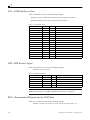
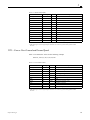
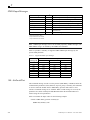
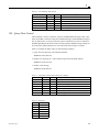
NMEA
R eferenc e Manual
NMEA Reference Manual
SiRF Technology, Inc.
148 East Brokaw Road
San Jose, CA 95112 U.S.A.
Phone: +1 (408) 467-0410
Fax: +1 (408) 467-0420
www.SiRF.com
1050-0042
December 2002, Revision 1.0
SiRF, the SiRF logo, and SiRFstar identity are registered trademarks of SiRF Technology, Inc. This document
contains information on a product under development at SiRF. The information is intended to help you evaluate
this product. SiRF reserves the right to change or discontinue work on this product without notice.
NMEA
Reference Manual
© 2002 SiRF Technology, Inc. All rights reserved.
No part of this work may be reproduced or transmitted in any form or by any means, electronic or
mechanical, including photocopying and recording, or by any information storage or retrieval system
without the prior written permission of SiRF Technology, Inc. unless such copying is expressly
permitted by United States copyright law. Address inquiries to Legal Department, SiRF Technology,
Inc., 148 East Brokaw Road, San Jose, California 95112, United States of America.
About This Document
This document contains information on SiRF products. SiRF Technology, Inc. reserves the right to
make changes in its products, specifications and other information at any time without notice. SiRF
assumes no liability or responsibility for any claims or damages arising out of the use of this document,
or from the use of integrated circuits based on this document, including, but not limited to claims or
damages based on infringement of patents, copyrights or other intellectual property rights. SiRF makes
no warranties, either express or implied with respect to the information and specifications contained in
this document. Performance characteristics listed in this data sheet do not constitute a warranty or
guarantee of product performance. All terms and conditions of sale are governed by the SiRF Terms
and Conditions of Sale, a copy of which you may obtain from your authorized SiRF sales
representative.
Getting Help
If you have any problems contact your SiRF representative or call or send an e-mail to the SiRF
Technology support group:
phone
+1 (408) 467-0410
e-mail
[email protected]
iii
Contents
Preface . . . . . . . . . . . . . . . . . . . . . . . . . . . . . . . . . . . . . . . . . . . . . . .
xxi
1. Output Messages . . . . . . . . . . . . . . . . . . . . . . . . . . . . . . . . . . . . . . .
1-1
GGA —Global Positioning System Fixed Data . . . . . . . . . . . . . . . . . .
1-2
GLL—Geographic Position - Latitude/Longitude . . . . . . . . . . . . . . . .
1-2
GSA—GNSS DOP and Active Satellites. . . . . . . . . . . . . . . . . . . . . . .
1-3
GSV—GNSS Satellites in View . . . . . . . . . . . . . . . . . . . . . . . . . . . . .
1-4
MSS—MSK Receiver Signal. . . . . . . . . . . . . . . . . . . . . . . . . . . . . . . .
1-4
RMC—Recommended Minimum Specific GNSS Data . . . . . . . . . . . .
1-4
VTG—Course Over Ground and Ground Speed . . . . . . . . . . . . . . . . .
1-5
2. Input Messages . . . . . . . . . . . . . . . . . . . . . . . . . . . . . . . . . . . . . . . .
2-1
Transport Message . . . . . . . . . . . . . . . . . . . . . . . . . . . . . . . . . . . . . . . .
2-1
NMEA Input Messages . . . . . . . . . . . . . . . . . . . . . . . . . . . . . . . . . . . .
2-2
100—SetSerialPort . . . . . . . . . . . . . . . . . . . . . . . . . . . . . . . . . . . . . . .
2-2
101—NavigationInitialization . . . . . . . . . . . . . . . . . . . . . . . . . . . . . . .
2-3
102—SetDGPSPort . . . . . . . . . . . . . . . . . . . . . . . . . . . . . . . . . . . . . . .
2-4
v
vi
103—Query/Rate Control . . . . . . . . . . . . . . . . . . . . . . . . . . . . . . . . . .
2-5
104—LLANavigationInitialization . . . . . . . . . . . . . . . . . . . . . . . . . . .
2-6
105—Development Data On/Off . . . . . . . . . . . . . . . . . . . . . . . . . . . . .
2-7
106—Select Datum . . . . . . . . . . . . . . . . . . . . . . . . . . . . . . . . . . . . . . .
2-7
MSK—MSK Receiver Interface . . . . . . . . . . . . . . . . . . . . . . . . . . . . .
2-8
NMEA Reference Manual—December 2002
Figures
xiii
xiv
NMEA Reference Manual—December 2002
Tables
Table 1-1
NMEA Output Messages . . . . . . . . . . . . . . . . . . . . . . . . . . . . . . . . .
1-1
Table 1-2
Supported NMEA output messages . . . . . . . . . . . . . . . . . . . . . . . . .
1-1
Table 1-3
GGA Data Format . . . . . . . . . . . . . . . . . . . . . . . . . . . . . . . . . . . . . .
1-2
Table 1-4
Position Fix Indicator . . . . . . . . . . . . . . . . . . . . . . . . . . . . . . . . . . . .
1-2
Table 1-5
GLL Data Format . . . . . . . . . . . . . . . . . . . . . . . . . . . . . . . . . . . . . . .
1-3
Table 1-6
GSA Data Format . . . . . . . . . . . . . . . . . . . . . . . . . . . . . . . . . . . . . . .
1-3
Table 1-7
Mode 1 . . . . . . . . . . . . . . . . . . . . . . . . . . . . . . . . . . . . . . . . . . . . . . .
1-3
Table 1-8
Mode 2 . . . . . . . . . . . . . . . . . . . . . . . . . . . . . . . . . . . . . . . . . . . . . . .
1-3
Table 1-9
GSV Data Format . . . . . . . . . . . . . . . . . . . . . . . . . . . . . . . . . . . . . . .
1-4
Table 1-10
MSS Data Format . . . . . . . . . . . . . . . . . . . . . . . . . . . . . . . . . . . . . . .
1-4
Table 1-11
RMC Data Format . . . . . . . . . . . . . . . . . . . . . . . . . . . . . . . . . . . . . .
1-5
Table 1-12
VTG Data Format. . . . . . . . . . . . . . . . . . . . . . . . . . . . . . . . . . . . . . .
1-5
Table 2-1
Supported NMEA input messages . . . . . . . . . . . . . . . . . . . . . . . . . .
2-2
Table 2-2
Set Serial Port Data Format . . . . . . . . . . . . . . . . . . . . . . . . . . . . . . .
2-3
Table 2-3
Navigation Initialization Data Format . . . . . . . . . . . . . . . . . . . . . . .
2-3
Table 2-4
Reset Configuration - Non SiRFLoc Platforms . . . . . . . . . . . . . . . .
2-4
xv
xvi
Table 2-5
Reset Configuration - SiRFLoc Specific . . . . . . . . . . . . . . . . . . . . .
2-4
Table 2-6
Set DGPS Port Data Format . . . . . . . . . . . . . . . . . . . . . . . . . . . . . . .
2-4
Table 2-7
Query/Rate Control Data Format (See example 1) . . . . . . . . . . . . .
2-5
Table 2-8
Messages . . . . . . . . . . . . . . . . . . . . . . . . . . . . . . . . . . . . . . . . . . . . .
2-5
Table 2-9
LLA Navigation Initialization Data Format . . . . . . . . . . . . . . . . . . .
2-6
Table 2-10
Reset Configuration . . . . . . . . . . . . . . . . . . . . . . . . . . . . . . . . . . . . .
2-6
Table 2-11
Development Data On/Off Data Format . . . . . . . . . . . . . . . . . . . . .
2-7
Table 2-12
Select Datum Data Format . . . . . . . . . . . . . . . . . . . . . . . . . . . . . . . .
2-7
Table 2-13
RMC Data Format . . . . . . . . . . . . . . . . . . . . . . . . . . . . . . . . . . . . . .
2-8
NMEA Reference Manual—December 2002
Preface
All SiRF product support a subset of the NMEA-0183 standard for interfacing marine
electronic devices as defined by the National Marine Electronics Association.
The NMEA Reference Manual provides details of NMEA messages developed and
defined by SiRF. It does not provide information about the complete NMEA-0183
interface standard.
Who Should Use This Guide
This manual was written assuming the user has a basic understanding of interface
protocols and their use.
How This Guide Is Organized
Chapter 1, “Output Messages” defines SiRF developed NMEA output messages.
Chapter 2, “Input Messages” defines SiRF developed NMEA input messages.
Related Manuals
You can refer to the following for more information:
•
NMEA-0183 Standard For Interfacing Marine Electronic Devices.
Contacting SiRF Technical Support
Address:
SiRF Technology Inc.
148 East Brokaw Road
San Jose, CA 95112 U.S.A.
SiRF Technical Support:
Phone:
+1 (408) 467-0410 (9 am to 5 pm Pacific Standard Time)
Email:
[email protected]
xxi
General enquiries:
xxii
Phone:
+1 (408) 467-0410 (9 am to 5 pm Pacific Standard Time)
Email:
[email protected]
NMEA Reference Manual—December 2002
1
Output Messages
Table 1-1 lists each of the NMEA output messages specifically developed and defined
by SiRF for use within SiRF products.
Table 1-1
NMEA Output Messages
Option
Description
GGA
Time, position and fix type data.
GLL
Latitude, longitude, UTC time of position fix and status.
GSA
GPS receiver operating mode, satellites used in the position solution,
and DOP values.
GSV
The number of GPS satellites in view satellite ID numbers, elevation,
azimuth, and SNR values.
MSS
Signal-to-noise ratio, signal strength, frequency, and bit rate from a
radio-beacon receiver.
RMC
Time, date, position, course and speed data.
VTG
Course and speed information relative to the ground.
A full description and definition of the listed NMEA messages are provided by the
next sections of this chapter.
Table 1-2 provides a summary of supported SiRF NMEA output messages by the
specific SiRF platforms.
Table 1-2 Supported NMEA output messages
Message
GGA
GLL
GSA
GSV
MSS
RMC
VTG
GSW2
Yes
Yes
Yes
Yes
Yes
Yes
Yes
SiRF Software Options
SiRFXTrac
Yes
Yes
Yes
Yes
No
Yes
Yes
SiRFLoc
Yes
Yes
Yes
Yes
No
Yes
Yes
1-1
1
GGA —Global Positioning System Fixed Data
Table 1-3 contains the values for the following example:
$GPGGA,161229.487,3723.2475,N,12158.3416,W,1,07,1.0,9.0,M, , , ,0000*18
Table 1-3 GGA Data Format
Name
Message ID
UTC Time
Latitude
N/S Indicator
Longitude
E/W Indicator
Position Fix Indicator
Satellites Used
HDOP
MSL Altitude1
Units
Geoid Separation1
Units
Age of Diff. Corr.
Diff. Ref. Station ID
Checksum
<CR> <LF>
Example
$GPGGA
161229.487
3723.2475
N
12158.3416
W
1
07
1.0
9.0
M
M
Units
meters
meters
meters
meters
second
Description
GGA protocol header
hhmmss.sss
ddmm.mmmm
N=north or S=south
dddmm.mmmm
E=east or W=west
See Table 1-4
Range 0 to 12
Horizontal Dilution of Precision
Null fields when DGPS is not used
0000
*18
End of message termination
1. SiRF Technology Inc. does not support geoid corrections. Values are WGS84 ellipsoid heights.
Table 1-4 Position Fix Indicator
Value
0
1
2
3
4
Description
Fix not available or invalid
GPS SPS Mode, fix valid
Differential GPS, SPS Mode, fix valid
GPS PPS Mode, fix valid
GPS RTK Mode, fix valid
Note – A valid position fix indicator is derived from the SiRF Binary M.I.D. 2 position
mode 1. See the SiRF Binary Reference Manual.
GLL—Geographic Position - Latitude/Longitude
Table 1-5 contains the values for the following example:
$GPGLL,3723.2475,N,12158.3416,W,161229.487,A*2C
1-2
NMEA Reference Manual—December 2002
1
Table 1-5 GLL Data Format
Name
Message ID
Latitude
N/S Indicator
Longitude
E/W Indicator
UTC Position
Status
Checksum
<CR> <LF>
Example
$GPGLL
3723.2475
N
12158.3416
W
161229.487
A
*2C
Units
Description
GLL protocol header
ddmm.mmmm
N=north or S=south
dddmm.mmmm
E=east or W=west
hhmmss.sss
A=data valid or V=data not valid
End of message termination
GSA—GNSS DOP and Active Satellites
Table 1-6 contains the values for the following example:
$GPGSA,A,3,07,02,26,27,09,04,15, , , , , ,1.8,1.0,1.5*33
Table 1-6 GSA Data Format
Name
Message ID
Mode 1
Mode 2
Satellite Used1
Satellite Used1
....
Satellite Used1
PDOP
HDOP
VDOP
Checksum
<CR> <LF>
Example
$GPGSA
A
3
07
02
1.8
1.0
1.5
*33
Units
Description
GSA protocol header
See Table 1-7
See Table 1-8
Sv on Channel 1
Sv on Channel 2
....
Sv on Channel 12
Position Dilution of Precision
Horizontal Dilution of Precision
Vertical Dilution of Precision
End of message termination
1. Satellite used in solution.
Table 1-7 Mode 1
Value
M
A
Description
Manual—forced to operate in 2D or 3D mode
2DAutomatic—allowed to automatically switch 2D/3D
Table 1-8 Mode 2
Value
1
2
3
Output Messages
Description
Fix Not Available
2D (<4SV’s used)
3D (>3SV’s used)
1-3
1
GSV—GNSS Satellites in View
Table 1-9 contains the values for the following example:
$GPGSV,2,1,07,07,79,048,42,02,51,062,43,26,36,256,42,27,27,138,42*71
$GPGSV,2,2,07,09,23,313,42,04,19,159,41,15,12,041,42*41
Table 1-9 GSV Data Format
Name
Message ID
Number of Messages1
Message Number1
Satellites in View
Satellite ID
Elevation
Azimuth
SNR (C/No)
....
Satellite ID
Elevation
Azimuth
SNR (C/No)
Checksum
<CR> <LF>
Example
Units
Description
$GPGSV
GSV protocol header
2
Range 1 to 3
1
Range 1 to 3
07
07
Channel 1 (Range 1 to 32)
79
degrees Channel 1 (Maximum 90)
048
degrees Channel 1 (True, Range 0 to 359)
42
dBHz
Range 0 to 99, null when not tracking
....
27
Channel 4 (Range 1 to 32)
27
degrees Channel 4 (Maximum 90)
138
degrees Channel 4 (True, Range 0 to 359)
42
dBHz
Range 0 to 99, null when not tracking
*71
End of message termination
1. Depending on the number of satellites tracked multiple messages of GSV data may be required.
MSS—MSK Receiver Signal
Table 1-10 contains the values for the following example:
$GPMSS,55,27,318.0,100,*66
Table 1-10 MSS Data Format
Name
Message ID
Signal Strength
Signal-to-Noise Ratio
Beacon Frequency
Beacon Bit Rate
Example
$GPMSS
55
27
318.0
100
Units
dB
dB
kHz
Description
MSS protocol header
SS of tracked frequency
SNR of tracked frequency
Currently tracked frequency
bits per second
Note – The MSS NMEA message can only be polled or scheduled using the MSK
NMEA input message. See “MSK—MSK Receiver Interface” on page 2-8.
RMC—Recommended Minimum Specific GNSS Data
Table 1-11 contains the values for the following example:
$GPRMC,161229.487,A,3723.2475,N,12158.3416,W,0.13,309.62,120598, ,*10
1-4
NMEA Reference Manual—December 2002
1
Table 1-11 RMC Data Format
Name
Message ID
UTC Time
Status1
Latitude
N/S Indicator
Longitude
E/W Indicator
Speed Over Ground
Course Over Ground
Date
Magnetic Variation2
Checksum
<CR> <LF>
Example
$GPRMC
161229.487
A
3723.2475
N
12158.3416
W
0.13
309.62
120598
Units
Description
RMC protocol header
hhmmss.sss
A=data valid or V=data not valid
ddmm.mmmm
N=north or S=south
dddmm.mmmm
E=east or W=west
knots
degrees True
ddmmyy
degrees E=east or W=west
*10
End of message termination
1. A valid status is derived from the SiRF Binary M.I.D 2 position mode 1. See the SiRF Binary Reference Manual.
2. SiRF Technology Inc. does not support magnetic declination. All “course over ground” data are geodetic WGS84
directions.
VTG—Course Over Ground and Ground Speed
Table 1-12 contains the values for the following example:
$GPVTG,309.62,T, ,M,0.13,N,0.2,K*6E
Table 1-12 VTG Data Format
Name
Message ID
Course
Reference
Course
Reference
Speed
Units
Speed
Units
Checksum
<CR> <LF>
Example
Units
Description
$GPVTG
VTG protocol header
309.62
degrees Measured heading
T
True
degrees Measured heading
M
Magnetic1
0.13
knots
Measured horizontal speed
N
Knots
0.2
km/hr
Measured horizontal speed
K
Kilometers per hour
*6E
End of message termination
1. SiRF Technology Inc. does not support magnetic declination. All “course over ground” data are geodetic WGS84
directions.
Output Messages
1-5
1
1-6
NMEA Reference Manual—December 2002
2
Input Messages
NMEA input messages are provided to allow you to control the Evaluation Receiver
while in NMEA protocol mode. The Evaluation Receiver may be put into NMEA
mode by sending the SiRF Binary protocol message “Switch to NMEA Protocol Message I.D. 129” (see the SiRF Binary Reference Manual). This can be done using a
user program or using the SiRFdemo software and selecting Switch to NMEA Protocol
from the Action menu (see the Evaluation Kit User’s Guide). If the receiver is in SiRF
Binary mode, all NMEA input messages are ignored. Once the receiver is put into
NMEA mode, the following messages may be used to command the module.
Transport Message
Start Sequence
$PSRF<MID>1
Payload
Data2
Checksum
*CKSUM3
End Sequence
<CR> <LF>4
1. Message Identifier consisting of three numeric characters. Input messages begin at MID 100.
2. Message specific data. Refer to a specific message section for <data>...<data> definition.
3. CKSUM is a two-hex character checksum as defined in the NMEA specification. Use of checksums
is required on all input messages.
4. Each message is terminated using Carriage Return (CR) Line Feed (LF) which is \r\n which is hex 0D
0A. Because \r\n are not printable ASCII characters, they are omitted from the example strings, but
must be sent to terminate the message and cause the receiver to process that input message.
Note – All fields in all proprietary NMEA messages are required, none are optional.
All NMEA messages are comma delimited.
2-1
2
NMEA Input Messages
Message
SetSerialPort
NavigationInitialization
SetDGPSPort
Query/Rate Control
LLANavigationInitialization
Development Data On/Off
Select Datum
MID1
100
101
102
103
104
105
106
MSK Receiver Interface
MSK
Description
Set PORT A parameters and protocol
Parameters required for start using X/Y/Z2
Set PORT B parameters for DGPS input
Query standard NMEA message and/or set output rate
Parameters required for start using Lat/Lon/Alt3
Development Data messages On/Off
Selection of datum to be used for coordinate
transformations.
Command message to a MSK radio-beacon receiver.
1. Message Identification (MID).
2. Input coordinates must be WGS84.
3. Input coordinates must be WGS84.
Note – NMEA input messages 100 to 106 are SiRF proprietary NMEA messages. The
MSK NMEA string is as defined by the NMEA 0183 standard.
Table 2-1 provides a summary of supported SiRF NMEA input messages by the
specific SiRF platforms.
Table 2-1 Supported NMEA input messages
Message ID
100
101
102
103
104
105
106
MSK
GSW2
Yes
Yes
Yes
Yes
Yes
Yes
Yes
Yes
SiRF Software Options
SiRFXTrac
Yes
Yes
No
Yes
Yes
Yes
Yes
No
SiRFLoc
Yes
Yes
No
Yes
Yes
Yes
Yes
No
100—SetSerialPort
This command message is used to set the protocol (SiRF Binary or NMEA) and/or the
communication parameters (baud, data bits, stop bits, parity). Generally, this command
is used to switch the module back to SiRF Binary protocol mode where a more
extensive command message set is available. When a valid message is received, the
parameters are stored in battery-backed SRAM and then the Evaluation Receiver
restarts using the saved parameters.
Table 2-2 contains the input values for the following example:
Switch to SiRF Binary protocol at 9600,8,N,1
$PSRF100,0,9600,8,1,0*0C
2-2
NMEA Reference Manual—December 2002
2
Table 2-2 Set Serial Port Data Format
Name
Message ID
Protocol
Baud
DataBits
StopBits
Parity
Checksum
<CR> <LF>
Example
$PSRF100
0
9600
8
1
0
*0C
Units
Description
PSRF100 protocol header
0=SiRF Binary, 1=NMEA
4800, 9600, 19200, 38400
8,71
0,1
0=None, 1=Odd, 2=Even
End of message termination
1. SiRF protocol is only valid for 8 data bits, 1stop bit, and no parity.
101—NavigationInitialization
This command is used to initialize the Evaluation Receiver by providing current
position (in X, Y, Z coordinates), clock offset, and time. This enables the Evaluation
Receiver to search for the correct satellite signals at the correct signal parameters.
Correct initialization parameters enable the Evaluation Receiver to acquire signals
quickly.
Table 2-3 contains the input values for the following example:
Start using known position and time.
$PSRF101,-2686700,-4304200,3851624,96000,497260,921,12,3*1C
Table 2-3 Navigation Initialization Data Format
Name
Message ID
ECEF X
ECEF Y
ECEF Z
ClkOffset
TimeOfWeek
WeekNo
ChannelCount
ResetCfg
Checksum
<CR> <LF>
Example
$PSRF101
-2686700
-4304200
3851624
96000
497260
921
12
3
*1C
Units
Description
PSRF101 protocol header
meters
X coordinate position
meters Y coordinate position
meters Z coordinate position
Hz
Clock Offset of the Evaluation Receiver1
seconds GPS Time Of Week
GPS Week Number
Range 1 to 12
See Table 2-4 and Table 2-5
End of message termination
1. Use 0 for last saved value if available.If this is unavailable, a default value of 96,000 will be used.
Input Messages
2-3
2
Table 2-4 Reset Configuration - Non SiRFLoc Platforms
Hex
0x01
0x02
0x03
0x04
0x08
Description
Hot Start— All data valid
Warm Start—Ephemeris cleared
Warm Start (with Init)—Ephemeris cleared,
initialization data loaded
Cold Start—Clears all data in memory
Clear Memory—Clears all data in memory and
resets receiver back to factory defaults
Table 2-5 Reset Configuration - SiRFLoc Specific
Hex
0x00
Description
Perform a hot start using internal RAM data. No
initialization data will be used.
0x01
Use initialization data and begin in start mode.
Unceretainties are 5 sec time accuracy and 300 km
position accuracy. Ephemeris data in SRAM is
used.
No initialization data is used, ephemeris data is
cleared, and warm start performed using remaining
data in RAM.
Initialization data is used, ephemeris data is
cleared, and warm start performed using remaining
data in RAM.
0x02
0x03
0x04
0x08
No initialization data is used. Position, time and
ephemeris are cleared and a cold start is performed.
No initialization data is used. Internal RAM is cleared
and a factory reset is performed.
102—SetDGPSPort
This command is used to control the serial port used to receive RTCM differential
corrections. Differential receivers may output corrections using different
communication parameters. If a DGPS receiver is used which has different
communication parameters, use this command to allow the receiver to correctly decode
the data. When a valid message is received, the parameters are stored in battery-backed
SRAM and then the receiver restarts using the saved parameters.
Table 2-6 contains the input values for the following example:
Set DGPS Port to be 9600,8,N,1.
$PSRF102,9600,8,1,0*12
Table 2-6 Set DGPS Port Data Format
Name
Message ID
2-4
Example
$PSRF102
Units
Description
PSRF102 protocol header
NMEA Reference Manual—December 2002
2
Table 2-6 Set DGPS Port Data Format
Name
Baud
DataBits
StopBits
Parity
Checksum
<CR> <LF>
Example
9600
8
1
0
*12
Units
Description
4800, 9600, 19200, 38400
8,7
0,1
0=None, 1=Odd, 2=Even
End of message termination
103—Query/Rate Control
This command is used to control the output of standard NMEA messages GGA, GLL,
GSA, GSV, RMC, and VTG. Using this command message, standard NMEA messages
may be polled once, or setup for periodic output. Checksums may also be enabled or
disabled depending on the needs of the receiving program. NMEA message settings are
saved in battery-backed memory for each entry when the message is accepted.
Table 2-7 contains the input values for the following examples:
1. Query the GGA message with checksum enabled
$PSRF103,00,01,00,01*25
2. Enable VTG message for a 1 Hz constant output with checksum enabled
$PSRF103,05,00,01,01*20
3. Disable VTG message
$PSRF103,05,00,00,01*21
Table 2-7 Query/Rate Control Data Format (See example 1)
Name
Message ID
Msg
Mode
Rate
CksumEnable
Checksum
<CR> <LF>
Example
Units
Description
$PSRF103
PSRF103 protocol header
00
See Table 2-8
01
0=SetRate, 1=Query
00
seconds Output—off=0, max=255
01
0=Disable Checksum, 1=Enable Checksum
*25
End of message termination
Table 2-8 Messages
Value
0
1
2
3
4
5
Input Messages
Description
GGA
GLL
GSA
GSV
RMC
VTG
2-5
2
Note – In TricklePower mode, update rate is specified by the user. When you switch to
NMEA protocol, message update rate is also required. The resulting update rate is the
product of the TricklePower Update rate and the NMEA update rate (i.e., TricklePower
update rate = 2 seconds, NMEA update rate = 5 seconds, resulting update rate is every
10 seconds, (2 X 5 = 10)).
104—LLANavigationInitialization
This command is used to initialize the Evaluation Receiver by providing current
position (in latitude, longitude, and altitude coordinates), clock offset, and time. This
enables the receiver to search for the correct satellite signals at the correct signal
parameters. Correct initialization parameters enable the receiver to acquire signals
quickly.
Table 2-9 contains the input values for the following example:
Start using known position and time.
$PSRF104,37.3875111,-121.97232,0,96000,237759,1946,12,1*07
Table 2-9 LLA Navigation Initialization Data Format
Name
Message ID
Lat
Lon
Alt
ClkOffset
TimeOfWeek
WeekNo
ChannelCount
ResetCfg
Checksum
<CR> <LF>
Example
$PSRF104
37.3875111
-121.97232
0
96000
237759
1946
12
Units
Description
PSRF104 protocol header
degrees Latitude position (Range 90 to -90)
degrees Longitude position (Range 180 to -180)
Altitude position
Clock Offset of the Evaluation Receiver1
seconds GPS Time Of Week
Extended GPS Week Number (1024 added)
meters
Hz
1
*07
Range 1 to 12
See Table 2-10
End of message termination
1. Use 0 for last saved value if available. If this is unavailable, a default value of 96,000 will be used.
Table 2-10 Reset Configuration
Hex
0x01
0x02
0x03
0x04
0x08
2-6
Description
Hot Start— All data valid
Warm Start—Ephemeris cleared
Warm Start (with Init)—Ephemeris cleared,
initialization data loaded
Cold Start—Clears all data in memory
Clear Memory—Clears all data in memory and
resets receiver back to factory defaults
NMEA Reference Manual—December 2002
2
105—Development Data On/Off
Use this command to enable development data information if you are having trouble
getting commands accepted. Invalid commands generate debug information that
enables the user to determine the source of the command rejection. Common reasons
for input command rejection are invalid checksum or parameter out of specified range.
Table 2-11 contains the input values for the following examples:
1. Debug On
$PSRF105,1*3E
2. Debug Off
$PSRF105,0*3F
Table 2-11 Development Data On/Off Data Format
Name
Message ID
Debug
Checksum
<CR> <LF>
Example
$PSRF105
1
*3E
Units
Description
PSRF105 protocol header
0=Off, 1=On
End of message termination
106—Select Datum
GPS receivers perform initial position and velocity calculations using an earth-centered
earth-fixed (ECEF) coordinate system. Results may be converted to an earth model
(geoid) defined by the selected datum. The default datum is WGS 84 (World Geodetic
System 1984) which provides a worldwide common grid system that may be translated
into local coordinate systems or map datums. (Local map datums are a best fit to the
local shape of the earth and not valid worldwide.)
Table 2-12 contains the input values for the following examples:
1. Datum select TOKYO_MEAN
$PSRF106,178*32
Table 2-12 Select Datum Data Format
Name
Message ID
Datum
Example
$PSRF106
178
Units
Description
PSRF106 protocol header
21=WGS84
178=TOKYO_MEAN
179=TOKYO_JAPAN
180=TOKYO_KOREA
181=TOKYO_OKINAWA
Checksum
<CR> <LF>
Input Messages
*32
End of message termination
2-7
2
MSK—MSK Receiver Interface
Table 2-13 contains the values for the following example:
$GPMSK,318.0,A,100,M,2,*45
Table 2-13 RMC Data Format
Name
Message ID
Beacon Frequency
Auto/Manual Frequency1
Beacon Bit Rate
Auto/Manual Bit Rate1
Interval for Sending $--MSS2
Example
$GPMSK
318.0
A
100
M
2
Units
kHz
sec
Description
MSK protocol header
Frequency to use
A : Auto, M : Manual
Bits per second
A : Auto, M : Manual
Sending of MSS messages for status
1. If Auto is specified the previous field value is ignored.
2. When status data is not to be transmitted this field is null.
Note – The NMEA messages supported by the Evaluation Receiver does not provide
the ability to change the DGPS source. If you need to change the DGPS source to
internal beacon, then this must be done using the SiRF binary protocol and then
switched to NMEA.
2-8
NMEA Reference Manual—December 2002
ADDITIONAL AVAILABLE PRODUCT INFORMATION
Part Number
1055-1031
1055-1030
APNT0003
APNT0004
APNT0006
APNT0007
APNT0010
APNT0015
APNT0017
APNT0018
APNT0019
APNT0020
APNT0021
APNT0023
APNT0028
APNT0029
APNT0030
APNT0032
APNT0033
APNT0035
APNT0036
Description
Product Inserts
SiRFstarIIe/LP Evaluation Kit
SiRFstarIIe/LP System Development Kit
Product Briefs
GSP2e/LP
GRF2i/LP
Application Notes
Troubleshooting Guide
System RF Front-end Requirements for SiRFstar Architectures
PCB Design Guidelines
Open Short Detector
GRF2i QFN Introduction
SiRFstarII S2AR Back-up Power Operation
Board Level Design for GSP2e/LP
SiRFstarIIe Low Power Operating Modes
SSII CPU Clock and Hardware Detection
Implementing User Tasks on the SiRFstarIIe
S2AM Hardware Reference Design Description
Effect of Increasing User Task Duty Cycle on Performance
Battery Backed SRAM Operation at 49MHz with the GSP2e/LP
GSP2e and GSP2e/LP Cache
EHPE and EVPE Calculations
Interfacing a 3-Wire Serial EEPROM with the GSP2e
Standard 0183 Message Versions in SiRF Receivers
Customer Design Review and Prototype Evaluation Process
Interfacing to a GSM Modem via the USER1 Protocol
SiRF Technology Inc.
SiRF France
148 East Brokaw
San Jose, CA 95112
Tel: +1-408-467-0410
Fax: +1-408-467-0420
Email: [email protected]
Website: http://www.sirf.com
Tel: +33-6-0717-7862
Fax: +44-1344-668157
Email: [email protected]
SiRF Texas
SiRF Germany
Tel: +1-972-239-6988
Fax: +1-972-239-0372
Email: [email protected]
Tel: +49-81-529932-90
Fax: +49-81-529931-70
Email: [email protected]
SiRF United Kingdom
SiRF Taiwan
Tel: +44-1344-668390
Fax: +44-1344-668157
Email: [email protected]
Tel: +886-2-2723-7853
Fax: +886-2-2723-7854
Email: [email protected]
NMEA Reference Manual
© 2002 SiRF Technology Inc. All rights reserved.
Products made, sold or licensed by SiRF Technology, Inc. are protected by one or more of the following United States patents: 5,488,378; 5,504,482; 5,552,794; 5,592,382; 5,638,077;
5,883,595; 5,897,605; 5,901,171; 5,917,383; 5,920,283; 6,018,704; 6,037,900; 6,041,280; 6,044,105; 6,047,017; 6,081,228; 6,114,992; 6,125,325; 6,198,765; 6,236,937; 6,249,542; 6,278,403;
6,282,231; 6,292,749; 6,297,771; 6,301,545; 6,304,216; 6,351,486; 6,351,711; 6,366,250; 6,389,291; 6,393,046; 6,400,753; 6,421,609; 6,427,120; 6,427,121; 6,453,238; and AU729,697.
Other United States and foreign patents are issued or pending. SiRF, SiRF plus Orbit design, and SiRFStar are registered trademarks of SiRF Technology, Inc. SnapLock, Foliage Lock, TricklePower,
SingleSat, SiRFLoc, SiRFDRive, and WinSiRF are trademarks of SiRF Technology, Inc. Other trademarks are property of respective companies.
This document contains information on SiRF products. SiRF reserves the right to make changes in its products, specifications and other information at any time without notice. SiRF assumes no liability
or responsibility for any claims or damages arising out of the use of this document, or from the use of integrated circuits based on this data sheet, including, but not limited to claims or damages based
on infringement of patents, copyrights or other intellectual property rights. No license, either expressed or implied, is granted to any intellectual property rights of SiRF. SiRF makes no warranties, either
express or implied with respect to the information and specification contained in this document. Performance characteristics listed in this document do not constitute a warranty or guarantee of product
performance. SiRF products are not intended for use in life support systems or for life saving applications. All terms and conditions of sale are governed by the SiRF Terms and Conditions of Sale, a
copy of which may obtain from your authorized SiRF sales representative.
December 2002