1
I771 Motherboard
Mini ITX SBC with Intel ® Core2 Quad /Core2 Duo Processor
LVDS, VGA, Dual Giga Ethernet, Mini-PCI, PCIe slot
User Manual / Engineering Spec.
Version 1.2
FCC Statement
This device complies with part 15 FCC rules. Operation is subject to
the following two conditions:
This device may not cause harmful interference.
This device must accept any interference received including
interference that may cause undesired operation.
This equipment has been tested and found to comply with the limits for a class "a"
digital device, pursuant to part 15 of the FCC rules. These limits are designed to
provide reasonable protection against harmful interference when the equipment is
operated in a commercial environment. This equipment generates, uses, and can
radiate radio frequency energy and, if not installed and used in accordance with the
instruction manual, may cause harmful interference to radio communications.
Operation of this equipment in a residential area is likely to cause harmful
interference in which case the user will be required to correct the interference at him
own expense.
I771 Motherboard User Manual
II
Copyright Notice
ALL RIGHTS RESERVED. No part of this document may be reproduced, copied,
translated, or transmitted in any form or by any means, electronic or mechanical, for
any purpose, without the prior written permission of the original manufacturer.
Trademark Acknowledgement
Brand and product names are trademarks or registered trademarks of their respective
owners.
Disclaimer
We. reserves the right to make changes, without notice, to any product, including
circuits and/or software described or contained in this manual in order to improve
design and/or performance. We assume no responsibility or liability for the use of the
described product(s), conveys no license or title under any patent, copyright, or masks
work rights to these products, and makes no representations or warranties that these
products are free from patent, copyright, or mask work right infringement, unless
otherwise specified. Applications that are described in this manual are for illustration
purposes only. We Communication Inc. makes no representation or warranty that such
application will be suitable for the specified use without further testing or
modification.
Warranty
We warrant that each of its products will be free from material and workmanship
defects for a period of one year from the invoice date. If the customer discovers a
defect, We will, at its option, repair or replace the defective product at no charge to
the customer, provided it is returned during the warranty period of one year, with
transportation charges prepaid. The returned product must be properly packaged in its
original packaging to obtain warranty service.
If the serial number and the product shipping data differ by over 30 days, the
in-warranty service will be made according to the shipping date. In the serial numbers
the third and fourth two digits give the year of manufacture, and the fifth digit means
the month (e. g., with A for October, B for November and C for December).
For example, the serial number 1W07Axxxxxxxx means October of year 2007.
I771 Motherboard User Manual
III
Packing List
Before using this Motherboard, please make sure that all the items listed below are
present in your package:
I771 Motherboard
I771 SBC User Manual
HDD SATA、IDE Cable
User‟s Manual & Driver CD
If any of these items are missing or damaged, contact your distributor or sales
representative immediately.
Customer Service
We provide service guide for any problem as follow steps: Please contact with your
distributor, sales representative, or our customer service center for technical support if
you need additional assistance. You may have the following information ready before
you call:
Product serial number
Peripheral attachments
Software (OS, version, application software, etc.)
Description of complete problem
The exact wording of any error messages
In addition, free technical support is available from our engineers every business day.
We are always ready to give advice on application requirements or specific
information on the installation and operation of any of our products. Please do not
hesitate to call or e-mail us.
I771 Motherboard User Manual
IV
Safety Precautions
Warning!
Always completely disconnect the power cord from your chassis
whenever you work with the hardware. Do not make connections
while the power is on. Sensitive electronic components can be
damaged by sudden power surges. Only experienced electronic
personnel should open the PC chassis.
Caution!
Always ground yourself to remove any static charge before
touching the CPU card. Modern electronic devices are very
sensitive to static electric charges. As a safety precaution, use a
grounding wrist strap at all times. Place all electronic components
in a static-dissipative surface or static-shielded bag when they are
not in the chassis.
I771 Motherboard User Manual
V
Safety and Warranty
1.
2.
3.
4.
5.
6.
7.
8.
9.
10.
11.
12.
13.
14.
15.
Please read these safety instructions carefully.
Please keep this user's manual for later reference.
Please disconnect this equipment from any AC outlet before cleaning. Do not use
liquid or spray detergents for cleaning. Use a damp cloth.
For pluggable equipment, the power outlet must be installed near the equipment
and must be easily accessible.
Keep this equipment away from humidity.
Put this equipment on a reliable surface during installation. Dropping it or letting
it fall could cause damage.
The openings on the enclosure are for air convection. Protect the equipment from
overheating. DO NOT COVER THE OPENINGS.
Make sure the voltage of the power source is correct before connecting the
equipment to the power outlet.
Position the power cord so that people cannot step on it. Do not place anything
over the power cord.
All cautions and warnings on the equipment should be noted.
If the equipment is not used for a long time, disconnect it from the power source
to avoid damage by transient over-voltage.
Never pour any liquid into an opening. This could cause fire or electrical shock.
Never open the equipment. For safety reasons, only qualified service personnel
should open the equipment.
If any of the following situations arises, get the equipment checked by service
personnel:
A. The power cord or plug is damaged.
B. Liquid has penetrated into the equipment.
C. The equipment has been exposed to moisture.
D. The equipment does not work well, or you cannot get it to work according to
the user‟s manual.
E. The equipment has been dropped and damaged.
F. The equipment has obvious signs of breakage.
Do not leave this equipment in an uncontrolled environment where the storage
temperature is below -20° C (-4°F) or above 60° C (140° F). It may damage the
equipment.
I771 Motherboard User Manual
VI
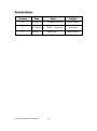
Revision History
Version
Date
Note
Author
1.2
2015.03.26
Jumper,Connector
Austin Chang
1.1
2011.04.22
BIOS、Connector
Henry Hsu
1.0
2009.01.12
Initial Draft
I771 Motherboard User Manual
VII
Aladin Huang
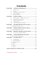
Contents
CHAPTER 1
1.1
1.2
1.3
1.4
1.5
CHAPTER 2
GENERAL INFORMATION .......................................1
INTRODUCTION ............................................................................... 1
FEATURE ......................................................................................... 1
MOTHERBOARD SPECIFICATIONS .................................................... 2
FUNCTION BLOCK ........................................................................... 3
BOARD DIMENSIONS........................................................................ 4
INSTALLATIONS.........................................................6
2.1
MEMORY MODULE(DIMM)INSTALLATION ................................ 6
2.2
2.3
2.4
I/O EQUIPMENT INSTALLATION ....................................................... 6
JUMPERS AND CONNECTORS ........................................................... 8
JUMPER SETTING............................................................................. 9
2.5
CONNECTORS AND PIN ASSIGNMENT ............................................ 12
CHAPTER 3
GRAPHIC DRIVER INSTALLATION ....................22
3.1 GRAPHIC DRIVER INSTALLATION......................................................... 22
CHAPTER 4
CHIPSET DRIVER INSTALLATION .....................26
4.1 CHIPSET DRIVER INSTALLATION ....................................................... 26
CHAPTER 5 ETHERNET DRIVER INSTALLATION..................30
5.1
CHAPTER 6
INSTALLATION OF ETHERNET DRIVER ........................................... 30
AUDIO DRIVER INSTALLATION..........................35
6.1 INSTALLATION OF AUDIO DRIVER........................................................ 35
CHAPTER 7
AMI BIOS SETUP ......................................................41
7.1
STARTING SETUP ........................................................................... 41
7.2
SYSTEM OVERVIEW....................................................................... 42
7.3 ADVANCED SETTING ......................................................................... 43
7.4 PCI/PNP ........................................................................................... 59
7.5 BOOT ................................................................................................ 65
7.6 SECURITY ......................................................................................... 69
7.7 CHIPSET ............................................................................................ 70
NOTE1: DIGITAL I/O SAMPLE CODE .............................................80
I771 Motherboard User Manual
VIII
CHAPTER
General Information
1
This chapter includes I771 Motherboard background
information.
Sections include:
Introduction
Feature
Motherboard Specification
Function Block
Board Dimensions
I771 Motherboard User Manual
1
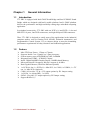
Chapter 1
1.1
General Information
Introduction
I771 SBC is equipped with Intel GM45 North Bridge and Intel ICH9M-E South
Bridge which are designed with Intel‟s mobile platform. Intel‟s GM45 platform
delivers the performance and high scalability cutting-edge embedded computing
application.
In peripheral connectivity, I771 SBC with one PCIE x 16 and PCIE x 1 slot and
Mini-PCI I/O ports, One PATA connectors, and eight Hi-Speed USB connectors.
Thus, I771 SBC is designed to satisfy most of the applications in the industrial
computer market, such as Gaming, POS, KIOSK, Industrial Automation, and
Programmable Control System. It is a compact design to meet the demanding
performance requirements of today‟s business and industrial applications.
1.2
Feature
Mini-ITX Form Factor ( 170mm x 170mm)
Supports Intel® Core 2 Quad/Core 2 Duo processors
System memory up to 4GB DDR2 667/800, 2xDIMM
Integrated Intel GM45 + ICH9M-E Chipset
Intel® GMA4500 MHD Graphic Engine, 384MB shared Memory.
Microsoft DirectX*10 support, Blu-ray* support @ 40 Mb/s
Dual Gigabit Ethernet ( Dual Fast Ethernet optional)
1 x PCIEx16 slot, 1 x PCIEx1,1 x Mini PCI, 4 x COM, 8 x USB2.0, 1 x TV
out, 1 x Mini PCIe (Optional)
COM 1/4: Provides +5V & +12V output options by JP1 Jumper setting
1 x PATA( 1 x 44 pins IDE), 3 x SATA
SATA2 : Provides +5V output options by JP3 Jumper setting
Support RAID 0,1,5
I771 Motherboard User Manual
1
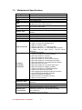
1.3
Motherboard Specifications
CPU Type
CPU FSB
CPU Socket
Chipset
BIOS
VGA
LVDS
LAN
Memory Type
LPC I/O
Keyboard/Mouse
IDE Interface
Sound
USB
Edge Connectors
On Board
Pin-Header
Connectors
Power Connector
Expansion Slots
Form Factor
Dimensions
Mechanical &
environmental
Intel® Core 2 Quad/Core 2 Duo Processor
1066 MHz
Intel Socket P type
Intel GM45/ICH9M-E
Award 4Mbit Flash
Intel GMA4500 MHD graphics engine
384MB shared with system memory
Intel® GM45 built in single- or Dual-channel panel support
up to 1920 x 1200, 24bit
2 x Giga LAN (Intel 82574L+82567LM)
2 x DDR2 DIMM socket, supports up to 4GB DDR2
800/667
Winbond W83627EHG integrated hardware monitoring
2 x PS/2 Keyboard/Mouse connectors
Dual channels; supports Ultra DMA 33/66/100
VIA VT1708B(Line-in, Line-out, Mic in)
8 ports, USB 2.0 (4 x USB Connector, 4 x USB pin-header )
1 x +12V DC-IN Jack
2 x PS/2 connector for keyboard/mouse
2 x DB9 for COM3 & COM4
1 x VGA out connector + 1 x DB9 for COM1
2 x Gigabit LAN RJ-45 + 1 x dual USB stack connector
1 x Audio Jack for Audio (Line-in, Line-Out, Mic-in)
(Optional)
1 x 44 pins box-header
1 x 10pins pin-header for Front Panel(2x5)
1 x 3pins pin-header for CPU Fan
1 x 3pins pin-header for System FAN
1 x 8pins pin-header for 5V/12V external power
2 x 2pins pin-header for 5V external power (Red)
1 x 2pins pin-header for 12V external power (Yellow)
1 x 4pins ATX 12V connector
2 x 2pins pin-header for Front Audio (with Amp.)
2 x 8pins pin-header for USB 5/6, 7/8(2x5)
1 x 10pins pin-header for COM2(RS232)(2x5)
1 x 40pins DF13 Connector for LVDS
1 x 3pins digital panel backlight brightness controller
1 x 7pins digital panel backlight controller
1 x 10pins pin-header for DIO(2x5)
3 x SATA connector for SATAI/II 3.0 Gb/s
1 x 6pins TV-Out connecter
Input: 4-pin ATX 12V Power input
1 x PCIEx1, 1 x PCIEx16, 1 x Mini-PCI. 1xMini-PCIe
(Optional)
Mini-ITX
170mm x 170mm
Operating temperature: 0 deg. C to 60 deg. C
Operating Humidity: 30 ~ 90% Relative humidity,
non-condensing
Certification: CE, FCC, RoHS
I771 Motherboard User Manual
2
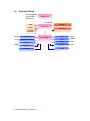
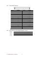
1.4
Function Block
Core 2 Quad /
Core 2 Duo
Processor
Mobile CPU
FSB 1066
CRT
Intel GM45
LVDS
DIMM x 2
DDR2 667/800 Max.4GB
PCIE x 16
TV Out
(Optional)
ATA100
1 x IDE Host
Intel ICH9M-E
3GB/s SATA II 1, SATAII 2
1GB/s
USB
480MB/s
VIA VT1708A
Audio
Realtek ALC655W83267EHG
Super IO
Realtek ALC655
Mini PCI
33MHz
Mini PCIe
PCIEx1
Realtek ALC655
SPI ROM
I771 Motherboard User Manual
LAN
3
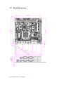
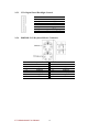
1.5
Board dimensions
I771 Motherboard User Manual
4
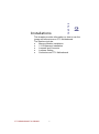
CHAPTER
Installations
2
This chapter provides information on how to use the
jumps and connectors on I771 Motherboard.
The Sections include:
Memory Module Installation
I / O Equipment Installation
Jumpers and Connects
Jumpers Setting
Connectors on I771 Motherboard
I771 Motherboard User Manual
5
Chapter 2
Installations
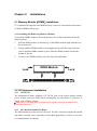
2.1 Memory Module(DIMM)Installation
I771 motherboard supports dual DDR2 memory socket for a maximum total memory
of 4GB in DDR2 memory type.
2.1.1 Installing and Removing Memory Modules
To install the DDR2 modules, locate the memory slot on the board and perform the
following steps:
1.
2.
Hold the DDR2 module so that the key of the DDR2 module align with those on
the memory slot.
Gently push the DDR2 module in an upright position until the clips of the slot
3.
close to hold the DDR2 module in place when the DDR2 module touches the
bottom of the slot.
To remove the DDR2 module, press the clips with both hands.
Lock
DDR2 Module
Lock
Lock
Lock
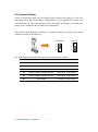
2.2 I/O Equipment Installation
2.2.1 12V DC-IN
The Motherboard allows plugging 12V DC-IN jack on the board without another
power module converter under power consumption by Intel Socket P processor in
GM45 with ICH9M-E chipset.
※Without power/reset OSD, short circuit pin 5 and 6 together to boot up the motherboard.
(Front Panel Connector)
2.2.2 PS/2 Keyboard and PS/2 Mouse
The Motherboard provides two PS/2 interface. The PS/2 connector supports Keyboard
and Mouse. In other cases, especially in embedded applications, a mouse is not used.
I771 Motherboard User Manual
6
Therefore, the BIOS standard setup menu allows you to select* “All, But Keyboard”
under the “Halt On”. This allows no-keyboard operation in embedded system
applications without the system halting under POST.
2.2.3 Serial COM ports
Three RS-232 connectors build in the rear I/O. Fourth optional COM ports support
RS-232. When an optional touch-screen is ordered with PPC, serial com port can
connect to a serial or an optional touch-screen. One optional COM port supports
RS232/422/485 choice through jumper setting.
2.2.4 Internal VGA
The Motherboard has one VGA port that can be connected to an external CRT/ LCD
monitor. Use VGA cable to connect to an external CRT / LCD monitor, and connect
the power cable to the outlet. The VGA connector is a standard 15-pin D-SUB
connector.
2.2.5 Ethernet interface
The Motherboard is equipped with Intel 82574L+82567LM chipset which is fully
compliant with the PCI 10/100/1000 Mbps Ethernet protocol compatible. It is
supported by major network operating systems. The Ethernet ports provide two
standard RJ-45 jacks.
2.2.6 USB ports
Eight USB devices (four with pin headers) may be connected to the system though an
adapter cable. Various adapters may come with USB ports. USB usually connect the
external system to the system. The USB ports support hot plug-in connection.
Whatever, you should install the device driver before you use the device.
2.2.7 Audio Jack ( Pin-header)
The Audio 5.1 channel capabilities are provided by a VIA VT1708B chipset
supporting digital audio outputs. The audio interface includes Mic-in,: line-in and
line-out.
I771 Motherboard User Manual
7
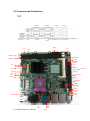
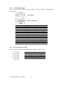
2.3 Jumpers and Connectors
TOP
COM4
DC Jack
CN1
PS/2
COM1
LAN1
LAN2
Mini-PCIe ( Optional)
COM3
VGA
IDE1
CN23
JP1
DIMM2
PANEL1
DIMM1
CN2
FAN1
SATA2
JP3
JP2
CN4
CN3
SATA3
Mini PCI
CN6
BT1
JP6
SATA1
PCIEx16
FAN2
CN7
PCIEx1
USB
USB
CN11
CN12
CN13
CN15
CN17
ATX12V
CN14
I771 Motherboard User Manual
JP4
8JP5
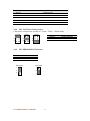
2.4 Jumper Setting
A pair of needle-nose pliers may be helpful when working with jumpers. If you have
any doubts about the best hardware configuration for your application, contact your
local distributor or sales representative before you make any changes. Generally, you
simply need a standard cable to make most connections.
The jumper setting diagram is as below. If a jumper shorts pin 1 and pin 2, the setting
diagram is shown as the right one.
Normal
Clear CMOS
1
1
2
2
3
3
The following tables list the function of each of the board's jumpers.
Label
Function
Note
JP1
COM Configure
3x1 header , pitch 2.0mm
JP2
LVDS VOLTAGE
2x3 header , pitch 2.54mm
JP3
SATA Configure
3x1 header , pitch 2.0mm
JP4
RS232 / RS422 / RS485 Selector
2x3 header , pitch 2.0mm
JP5
RS232 / RS422 / RS485 Selector
3x4 header , pitch 2.0mm
JP6
Clear CMOS
3x1 header , pitch 2.0mm
I771 Motherboard User Manual
9
2.4.1 JP6: Clear CMOS
User must make sure the power supply to turn off the power supply before setting
Clear CMOS. Users remember to setting jumper back to Normal before turning on the
power supply. Default: 2 short 3.
Clear CMOS
Normal
1
1
2
2
3
3
Pin No.
1 Short 2
2 Short 3
Functions
Clear CMOS
Normal
JP4 : COM1 RS232 / RS422 / RS485 Function Selector
The jumper can be configured to operate COM1 in RS-232/422/485 mode. And the
setting must be cooperated with the 2.4.2 settings. Default 1 short 2.
RS232
RS422
RS485
1
2
1
2
1
2
3
4
3
4
3
4
5
6
5
6
5
6
Pin No.
1 Short 2
3 Short 4
5 Short 6
Functions
RS232
RS422
RS485
2.4.2 JP5: RS232 / RS422 / RS485 Selector
The jumper can be configured to operate COM1 in RS-232/422/485 mode. And the
setting must be cooperated with JP4 settings.
RS232
RS422/485
1
3
1
3
4
6
4
6
7
9
7
9
10
12 10
RS232
1-2
4-5
7-8
10-11
12
2.4.3 JP1: COM Configure
JP1 can be configured to provide RI/+5V/+12V on COM1/COM4.
11
1
12
2
1
I771 Motherboard User Manual
10
RS422/485
2-3
5-6
8-9
11-12
Pin No.
Functions
1
Short 2
COM1 RI =RI
3
Short 4
COM1 RI = +12V
5
Short 6
COM1 RI = +5V
7
Short 8
COM4 RI =RI
9
Short 10
COM4 RI = +12V
11 Short 12
COM4 RI = +5V
2.4.4 JP2: LCD Panel Voltage Select
CN4 can be configured to operate in 3.3Volts / 5Volts / 12Volts mode.
3.3Volts
5Volts
12Volts
1
2
1
2
1
2
3
4
3
4
3
4
5
6
5
6
5
6
Pin No.
1 Short 2
3 Short 4
5 Short 6
2.4.5 JP3: HDD/DOM SATA2 Select
Pin No.
1 Short 2
2 Short 3
Functions
SATA DOM
SATA HDD
SATA DOM
SATA HDD
1
1(Default)
2
2
3
3
I771 Motherboard User Manual
11
Functions
3.3Volts Selected
5Volts Selected
12Volts Selected
2.5 Connectors and Pin Assignment
The table below lists the function of each of the board‟s connectors.
Label
Function
Note
CN4
DF13-40DP-1.25V
3x1 header, pitch 2.54mm
CN3
LVDS LCD Output Connector
Digital Panel Backlight Brightness
Control
Inverter Connecter
CN14
Serial port COM2
9pin COM port
IDE1
IDE Connector
44Pin IDE Conn.
USB
USB PIN HEADER
4x2 Pin Header
FAN1_SYS
FAN CONNECTOR
3x1 Pin Header
FAN2_CPU
FAN CONNECTOR
3x1 Pin Header
PANEL1
System Function Connector
5x2 header ,pitch 2.0mm
CN17
Front Audio (Right)
1x2 header ,pitch 2.54mm
CN15
Front Audio (Left)
1x2 header ,pitch 2.54mm
CN13(Yellow)
12V External Power
2x1 header, pitch 2.54mm
CON11(Red)
5V External Power
2x1 header, pitch 2.54mm
CON12(Red)
5V External Power
2x1 header, pitch 2.54mm
CN2
5V/12V External Power
4x2 header ,pitch 2.54mm
CN1
TV Out
3x2 header ,pitch 2.54mm
CN7
Digital I/O
10 pin Digital I/O function
ATX_PWR
12V DC Connector
2x2 Pin Connecter
PWIN1
12V DC Connector
4 Pin Connecter
CN23
MEJ TAG
2x4 wafer 1.27mm
CN6
I771 Motherboard User Manual
12
7x1 header, pitch 2.54mm
2.5.1 CN4: LVDS Connector
Pin No.
1
3
5
7
9
11
13
15
17
19
21
23
25
27
29
31
33
35
37
39
SYMBOL
LCDVDD
LCDVDD
LCDVDD
GND
GND
GND
GND
GND
GND
GND
GND
GND
GND
GND
GND
GND
GND
GND
GND
GND
Pin No.
2
4
6
8
10
12
14
16
18
20
22
24
26
28
30
32
34
36
38
40
SYMBOL
LVDS_ATX0LVDS_ATX0+
LVDS_ATX1LVDS_ATX1+
LVDS_ATX2LVDS_ATX2+
LVDS_ATXCLKLCDS_ATXCLK+
ATX3ATX3+
LVDS_BTX0LVDS_BTX0+
LVDS_BTX1LVDS_BTX1+
LVDS_BTX2LVDS_BTX2+
LVDS_BTXCLKLVDS_BTXCLK+
BTX3BTX3+
2.5.2 CN6: Digital Panel Backlight Brightness Control
Pin No.
1
2
3
I771 Motherboard User Manual
SYMBOL
VCC(5V)
Black Light Control
GND
13
2.5.3 CN3: Digital Panel Backlight Control
Pin No.
1
2
3
4
5
6
7
SYMBOL
+12V
+12V
+12V
GND
Black Light Control
GND
Black Light EN 5V
2.5.4 PSKBM1: PS2 Keyboard/Mouse Connector
Pin No.
1
2
3
4
5
6
PS/2 Keyboard
SYMBOL
KDATA
NC1
Ground
VCC(5V)
KBCLK
NC2
I771 Motherboard User Manual
Pin No.
7
8
9
10
15
16
14
PS/2 Mouse
SYMBOL
MDATA
NC3
Ground
VCC(5V)
MSCLK
NC4
2.5.5 D-SUB Dual Output
The serial port COM1, which is option for RS232 / RS422 / RS485, is the Winbond
I/O serial port.
COM1
C1
Up: 9(Male)
C6
V1
Down: 15(Female)
V6
V11
VGA
Pin No.
C1
C2
C3
C4
C5
C6
C7
C8
C9
SYMBOL
DCD4/485TXRXSRD4/485TXRX+
STD4/422RX+
DTR4/422RXGND
NDSRA
NRTSA
NCTSA
NRIA
Pin No.
V1
V2
V3
V4
V5
V6
V7
V8
V9
V10
V11
V12
V13
V14
V15
SYMBOL
R
G
B
NA
GND
GND
GND
GND
VCC(5V)
GND
NA
DDC_DATA
CRT_HS
CRT_VS
DDC_CLK
2.5.6 CN14: Serial port COM2
The serial port COM2, which is Winbond I/O support, is RS232 only.
10
8
6
4
2
9
7
5
3
1
I771 Motherboard User Manual
Pin
10
8
6
4
2
SYMBOL
GND
NRI1A
NCTS1A
NRTS1A
NDSR1A
15
Pin
9
7
5
3
1
SYMBOL
GND
NDTR1A
NTXD1A
NRXD1A
NDCD1A
2.5.7 D-SUB Dual Serial Port
The serial port COM3/4, RS232 only, from A1 to A9 is COM3, and B1 to B9 is
COM4, which is supported by Fintek.
COM4
Pin No.
A1
A2
A3
A4
A5
A6
A7
A8
A9
B1
B6
A1
A6
SYMBOL
FK_NDCD1
FK_NSIN1
FK_NSOUT1
FK_NDTR1
GND
FK_NDSR1
FK_NRTS1
FK_NCTS1
FK_NRI1
COM3
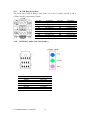
2.5.8 AUDIO401: Audio Jack ( Pin-header )
Color
Blue
Green
Pink
C0~C4
B1~B4
A1~A4
Signal
Line In
Line Out
Microphone In
Pin-Header
Line in
Line out
Mic in
I771 Motherboard User Manual
16
Pin No.
B1
B2
B3
B4
B5
B6
B7
B8
B9
SYMBOL
FK_NDCD2
FK_NSIN2
FK_NSOUT2
FK_NDTR2
GND
FK_NDSR2
FK_NRTS2
FK_NCTS2
FK_NRI2
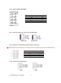
2.5.9 IDE1: 44 pins IDE Connector
1
2
44
Pin No.
1
3
5
7
9
11
13
15
17
19
21
23
25
27
29
31
33
35
37
39
41
43
I771 Motherboard User Manual
SYMBOL
RESET
DD7
DD6
DD5
DD4
DD3
DD2
DD1
DD0
GND1
DREQ
DIOW#
DIOR#
IO_RDYD
DACK#
IRQ
DA1
DA0
DCS#1
DASP#
+5V1
GND2
17
Pin No.
2
4
6
8
10
12
14
16
18
20
22
24
26
28
30
32
34
36
38
40
42
44
SYMBOL
GND3
DD8
DD9
DD10
DD11
DD12
DD13
DD14
DD15
NC1
GND4
GND5
GND6
CSEL
GND7
IOCS16#
CBL_ID#
DA2
DCS#3
GND8
+5V2
NC2
2.5.10 USB: USB PIN HEADER
2
1
4
3
6
5
8
7
USB1
Pin
SYMBOL
Pin
SYMBOL
2
+5V
1
+5V
4
USB_DATA13
USB_DATA06 USB_DATA1+ 5 USB_DATA0+
8
GND
7
GND
2.5.11 FAN1_SYS/FAN2_CPU: FAN CONNECTOR
FAN1_SYS
FAN2_CPU
2.5.12 PANEL1: Front Panel System Function Connector
※Without power/reset OSD, short circuit pin 5 and 6 together to boot up the motherboard.
2
4
6
8
10
Pin
2
4
6
8
10
1
3
5
7
9
SYMBOL
HD_LED+
HD_LEDRT_BT1
RT_BT2
5VSB
Pin
1
3
5
7
9
2.5.13 CN15/CN17: Front Audio
CN17
I771 Motherboard User Manual
CN15
18
SYMBOL
PW_LED+
PW_LEDPW_BT1
PW_BT2
RSEV
2.5.14 CN11/CN12/CN13/CN2: External Power
Yellow
Red
CN13
CN11/CN12
CN2
2.5.15 PWIN1: DC Jack ( +12V) / Input
2.5.16 ATX_PWR / Input: 12V DC Connector
Pin
1
2
3
4
SYMBOL
Ground
Ground
+12V
+12V
2.5.17 : CN7: Digital I/O Connector
2
4
6
8
10
Pin
2
4
6
8
10
1
3
5
7
9
SYMBOL
+5V
Out1
Out0
IN1
IN0
Pin
1
3
5
7
9
SYMBOL
GND
Out3
Out2
IN3
IN2
2.5.18 : CN1: TV out Connector ( Optional)
5
6
3
4
1
2
Pin SYMBOL Pin
SYMBOL
5
DACC_L
6 TV_DCONSEL1_MCH
3
DACB_L
4 TV_DCONSEL0_MCH
1
GND
2
DACA_L
I771 Motherboard User Manual
19
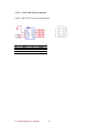
2.5.19 : CN23: ME JTAG( Optional)
CN23 is ME JTAG for Intel iAMT function.
Pin
1
2
3
4
SYMBOL
NC
GND
+1.05V
+3.3V
Pin
5
6
7
8
SYMBOL
TDO
TCK
TMS
TDI
I771 Motherboard User Manual
20
CHAPTER
3
Graphic Driver Installation
This chapter offers information on the chipset software
Installation utility
Graphic Driver Installation
I771 Motherboard User Manual
21
Chapter 3
Graphic Driver Installation
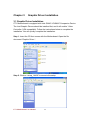
3.1 Graphic Driver Installation
I771 Motherboard is equipped with Intel GM45 / ICH9M-E Companion Device.
The Intel Graphic Drivers should be installed first, and it will enable “Video
Controller (VGA compatible). Follow the instructions below to complete the
installation. You will quickly complete the installation.
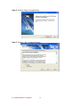
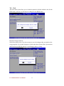
Step.1. Insert the CD that comes with the Motherboard. Open the file
document “Graphic Driver “.
Step.2. Click on “winxp_14428” to execute the setup.
I771 Motherboard User Manual
22
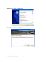
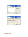
Step.3. Click on “Next “ to install Driver.
Step.4. Click on “Next “ to install Driver.
I771 Motherboard User Manual
23
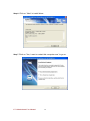
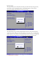
Step.5. Click on “Yes “ to agree License.
Step.7. Click on “Yes, I want to restart this computer now“ to go on.
I771 Motherboard User Manual
24
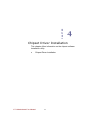
CHAPTER
4
Chipset Driver Installation
This chapter offers information on the chipset software
Installation utility
Chipset Driver Installation
I771 Motherboard User Manual
25
Chapter 4
Chipset Driver Installation
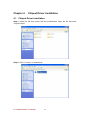
4.1 Chipset Driver Installation
Setp.1. Insert the CD that comes with the motherboard. Open the file document
“Chipset Driver”.
Setp.2. Click on “Setup“ to install driver.
I771 Motherboard User Manual
26
Setp.3. Click on “Next“ to install driver.
Setp.4. Click on “Yes “ to agree License
I771 Motherboard User Manual
27
Setp.5. Click on “Next“ to install driver.
Step.7. Click on “Yes, I want to restart this computer now“ to go on.
I771 Motherboard User Manual
28
CHAPTER
5
Ethernet Driver Installation
This chapter offers information on the Ethernet software
installation utility.
Sections include:
Installation of Ethernet Driver
I771 Motherboard User Manual
29
Chapter 5
5.1
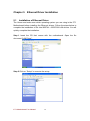
Ethernet Driver Installation
Installation of Ethernet Driver
The Users must make sure which operating system you are using in the I771
Motherboard before installing the Ethernet drivers. Follow the steps below to
complete the installation of the Intel 82574L + 82567LM LAN drivers. You will
quickly complete the installation.
Step.1. Insert the CD that comes with the motherboard. Open the file
document “LAN Driver”.
Step.2 Click on “Setup” to execute the setup.
I771 Motherboard User Manual
30
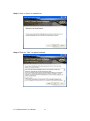
Step.3. Click on “Next“ to install driver.
Step.4. Click on “I accept the terms in the license agreement.”
I771 Motherboard User Manual
31
Setp.5. Click on “Advanced Network Services“ and go on.
Setp.6. Click on “Next“ to install driver.
I771 Motherboard User Manual
32
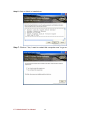
Setp.7.
Click on “Finish“.
I771 Motherboard User Manual
33
CHAPTER
6
Audio Driver Installation
This chapter offers information on the Audio software
installation utility.
Sections include:
Installation of Audio Driver
I771 Motherboard User Manual
34
Chapter 6
Audio Driver Installation
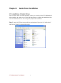
6.1 Installation of Audio Driver
The users must make sure which operating system you are using in the I771 Motherboard
before installing the Audio drivers. Follow the steps below to complete the installation of the
VIA VT1708B Audio drivers. You will quickly complete the installation.
Step.1. Insert the CD that comes with the motherboard. Open the file “Audio driver”
and click on “Setup” to execute the setup.
I771 Motherboard User Manual
35
Step.2. Click on “Next“ to install driver.
Step.3. Click on “Yes “ to agree License
I771 Motherboard User Manual
36
Step.4. Click on “Next“ to install driver.
Step.5. Click on “Next“ to install driver.
I771 Motherboard User Manual
37
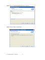
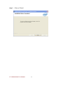
Step.6. Click on “Next“ to install driver.
Step.7 Click on “Yes, I want to restart this computer now“ to go on.
I771 Motherboard User Manual
38
Step.9 After restart computer, cliick on “HD ADeck “ to set up Line in/Mic in.
Step.10 Select ” Analog to the Line out “ and click “ Next page”
Step.11 Select ” Analog to the Line out “ and move the bar.
I771 Motherboard User Manual
39
CHAPTER
7
AMI BIOS Installation
This chapter describes the different settings available in
the AMI BIOS that comes with the board. This chapter
offers information on the Award BIOS installation utility.
Sections include:
Starting Setup
System Overview
Advanced Setting
PCI/PnP
Boot
Security
Chipset
I771 Motherboard User Manual
40
Chapter 7
7.1
AMI BIOS SETUP
Starting Setup
Your computer comes with a hardware configuration program called BIOS Setup that
allows you to view and set system parameters.
The BIOS (Basic Input / Output System) is a layer of software, called „firmware‟, that
translates instructions from software (such as the operating system) into instructions
that the computer hardware can understand. The BIOS settings also identify installed
devices and establish special features.
ENTERING BIOS SETUP
You can access the BIOS program just after you turn on your computer. Just press the
DEL key when the following prompt appears:
Press <DEL> to enter Setup.
When you press <DEL> to enter BIOS Setup, the system interrupts the Power-On
Self-Test (POST).
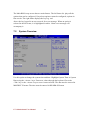
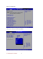
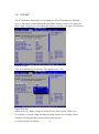
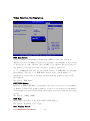
When you first enter the BIOS Setup Utility, you will enter the Main setup screen.
You can always return to the Main setup screen by selecting the Main tab. There are
two Main Setup options. They are described in this section. The Main BIOS Setup
screen is shown below.
I771 Motherboard User Manual
41
The Main BIOS setup screen has two main frames. The left frame dis- plays all the
options that can be configured. Grayed-out options cannot be configured; options in
blue can be. The right frame displays the key leg- end.
Above the key legend is an area reserved for a text message. When an option is
selected in the left frame, it is highlighted in white. Often a text message will
accompany it.
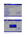
7.2
System Overview
Use this option to change the system time and date. Highlight System Time or System
Date using the <Arrow> keys. Enter new values through the keyboard. Press the
<Tab> key or the <Arrow> keys to move between fields. The date must be entered in
MM/DD/YY format. The time must be entered in HH:MM:SS format
I771 Motherboard User Manual
42
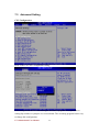
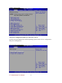
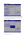
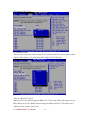
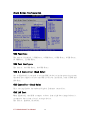
7.3
Advanced Setting
CPU Configuration
Press “Enter” to CPU Configuration setting.
CPU configuration differs from writing an executable program. It is equivalent to
setting dip switches or jumpers on a circuit board. The executing program has no way
to change this configuration.
I771 Motherboard User Manual
43
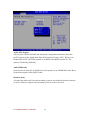
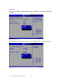
IDE/SATA Configuration
The IDE Configuration menu is used to change and/or set the configuration of the
IDE devices installed in the system.
I771 Motherboard User Manual
44
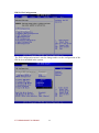
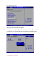
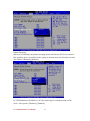
Super IO Configuration
Allows you to select the Serial Port base address.
I771 Motherboard User Manual
45
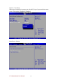
Hardware Health Configuration
CPU Temperature
The onboard hardware monitor automatically detects and displays the CPU
temperatures.
I771 Motherboard User Manual
46
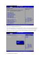
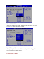
ACPI Configuration
Advanced Configuration and Power Interface (ACPI)
provides an open standard for unified operating system-centric device configuration
and power management.
General ACPI Configuration
I771 Motherboard User Manual
47
ACPI APIC Support
Allows you to enable or disable the Advanced Configuration and Power Interface
(ACPI) support in the Application-Specific Integrated Circuit (ASIC). When set to
Enabled, the ACPI APCI table pointer is included in the RSDT pointer list. The
options: [Disabled], [Enabled].
AMI OEMB table
Set this value to allow the ACPI BIOS to add a pointer to an OEMB table in the Root
System Description Table (RSDT) table.
Headless mode
A feature that allows the bios and operating system to run without keyboard, monitor,
or mouse. Must be supported by operating system in order to be used.
I771 Motherboard User Manual
48
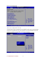
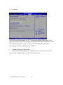
AHCI Configuration
AHCI mode is enabled in the BIOS where 3 settings are commonly available: IDE,
AHCI, and RAID. The last two (AHCI and RAID) require a floppy disk with the
driver that can be introduced into the operating system installation through F6.
Otherwise, the hard disks won't be detected.
I771 Motherboard User Manual
49
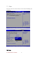
ASF Configuration
Alert Standard Format
The term "system manageability" represents a wide range of technologies that enable
remote system access and control in both OS-present and OS-absent environments.
These technologies are primarily focused on minimizing on-site I/T maintenance,
maximizing system availability and performance to the local user, maximizing remote
visibility of (and access to) local systems by I/T managers and minimizing the system
power consumption required to keep this remote connection intact.
I771 Motherboard User Manual
50
Intel AMT Configuration
Allows you to enable or disable iAMT support.
Active Management Technology (AMT) is hardware-based technology for remotely
managing and securing PCs out-of-band. Currently, Intel AMT is available in desktop
PCs with Intel Core 2 processor with Intel vPro technology and available in laptop
PCs with Centrino or Centrino 2 platform with vPro technology
I771 Motherboard User Manual
51
Intel Robson Configuration
Allows you to configure Intel Robson Tech.
The technology attempts to decrease hard drive usage by moving frequently accessed
data over to the flash memory. Flash memory can be accessed faster than hard drives
and requires less power to operate, thereby allowing laptops to operate faster while
also being more power efficient.
I771 Motherboard User Manual
52
Intel VT-d Configuration
Allows you to configure Intel VT-d Tech.
An input/output memory management unit (IOMMU) enables guest virtual machines
to directly use peripheral devices, such as Ethernet, accelerated graphics cards, and
hard-drive controllers, through DMA and interrupt remapping
I771 Motherboard User Manual
53
MPS Configuration
I771 Motherboard User Manual
54
PCI Express Configuration
The Expansion Slot Utility allows you to change the number of "lanes" available for
PCIe cards to utilize.
I771 Motherboard User Manual
55
Smbios Configuration
System Management BIOS (SMBIOS) specification defines data structures (and
access methods) in a BIOS which allows a user or application to store and retrieve
information specifically about the computer in question.
I771 Motherboard User Manual
56
USB Configuration
Legacy USB Support
Allows you to enable or disable support for USB devices on legacy operating system
(OS). Setting to Auto allows the system to detect the presence of USB devices at
startup. If detected, the USB controller legacy mode is enabled. If no USB device is
detected, the legacy USB support is disabled. The options: [Disabled], [Enabled],
[Auto].USB 2.0 Controller Allows you to enable or disable the USB 2.0 controller.
The options: [Disabled] [Enabled].
I771 Motherboard User Manual
57
RTC Configuration
Real time clock alarm is a feature that can be used to allow a computer to 'wake up'
after shut down to execute tasks every day or on a certain day
I771 Motherboard User Manual
58
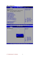
7.4 PCI/PnP
The PCI PnP menu items allow you to change the advanced settings for PCI/PnP
devices. The menu includes setting IRQ and DMA channel resources for either PCI/
PnP or legacy ISA devices, and setting the memory size block for legacy ISA devices
Clear NVRAM
Clear NVRAM during system boot. The options: [No], [Yes].
Plug & Play O/S
When set to [No], BIOS configures all the devices in the system. When set to
[Yes] and if you install a Plug and Play operating system, the operating system
configures the Plug and Play devices not required for boot.
I771 Motherboard User Manual
59
The options: [No] [Yes].
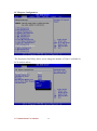
PCI Latency Timer
Allows you to select the value in units of PCI clocks for the PCI device latency timer
register. The options: [32] [64] [96] [128] [160] [192] [224] [248].
Allocate IRQ to PCI VGA
When set to [Yes], BIOS assigns an IRQ to PCI VGA card if the card requests for an
IRQ. When set to [No], BIOS does not assign an IRQ to the PCI VGA card even if
requested. The options: [No] [Yes].
I771 Motherboard User Manual
60
Palette Snooping
When set to [Enabled], the palette snooping feature informs the PCI devices that an
ISA graphics device is installed in the system so that the latter can function correctly.
The options: [Disabled] [Enabled].
PCI IDE BusMaster the BIOS use PCI bus mastering for reading/writing to IDE
device. The options: [Disabled], [Enabled].
I771 Motherboard User Manual
61
OffBoard PCI/ISA IDE Card
Allows you to set the PCI slot number. The options: [Auto], [PCI Slot1], [PCI Slot2],
[PCI Slot 3], [PCI Slot4], [PCI Slot5], [PCI Slot6].
IRQ3,4,5,7,9,10,11,14,15
Allows you to specify IRQ that is available to be used by PCI/PnP or Legacy ISA
device. The options: [Available], [Reserved].
I771 Motherboard User Manual
62
DMA Channel 0,1,3,5,6,7
DMA Channel PCI/PMP functions. The options: [Available], [Reserved].
Reserved Memory Size
Set the size of memory block to reserve for legacy ISA devices.
The options: [Disabled], [16 K], [32 K], [64 K].
I771 Motherboard User Manual
63
I771 Motherboard User Manual
64
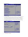
7.5 Boot
Boot Setting Configuration
Quick Boot
Enable this item allows the BIOS to skip some power on self test (POST) while
booting to decrease the time needed to boot the system. When set to [Disabled], BIOS
performs all the POST items. The options: [Disabled], [Enabled].
I771 Motherboard User Manual
65
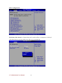
Quiet Boot
Allows you to display Normal POST message or OEM logo. The options: [Disabled],
[Enabled].
Boot up Num-Lock
Allows you to select the power-on state for the NumLock. The options: [Off], [On].
I771 Motherboard User Manual
66
Wait for „F1‟ If Error
When set to Enabled, the system waits for the F1 key to be pressed when error
occurs. The options: [Disabled], [Enabled].
Boot Device Priority
I771 Motherboard User Manual
67
Boot Device Priority
Select the priority of Boot devices.
I771 Motherboard User Manual
68
7.6 Security
Select Security Setup from the I771 Setup main BIOS setup menu. All
Security Setup options, such as password protection and virus protec- tion
are described in this section. To access the sub menu for the following items, select the item and press <Enter>:
ï Change Supervisor Password
ï Boot sector Virus protection: The boot sector virus protection will
warn if any program tries to write to the boot sector.
I771 Motherboard User Manual
69
7.7 Chipset
This menu controls the advanced features of the onboard Northbridge and
Southbridge.
TMRC Mode
I771 Motherboard User Manual
70
Select TMRC Mode.
The choice: Enabled, Disabled
TS on DIMM
Enable/Disable Thermal Sensor on DIMM.
The choice: Enabled, Disabled
Memory Hole
In order to improve performance, certain space in memory is reserved for
ISA cards.
This memory must be mapped into the memory space below 16MB.
The choice: Disabled, 15MB-16MB.
Boots Graphic Adapter Priority
Select which graphics controller to use as the primary boot device.
The choice: IGD, PCI/IGD, PCI/PEG, PEG/IGD, PEG/PCI.
Internal Graphics Mode Select
Select the amount of system memory used by the internal graphics
device.
The choice: Enabled, 32MB, Enabled, 64MB, Enabled, 128MB.
Max TOLUD
Maximum Value of TOLUD
The choice: 3G Bytes, 2.5G Bytes, 2G Bytes
GFx Low Power Mode
This option is applicable for SFF only
The choice: Disabled, Enabled.
PEG Port
This setting allows you to select whether to use the on-chip graphics
processor or the PCI Express card. When set to [Auto], the BIOS checks
to see if a PCI Express graphics card is installed. If it detects that a PCI
Express graphics card is present, the motherboard boots up using that
card. Otherwise, it defaults to the onboard graphics processor.
The choice: Auto, Disabled.
I771 Motherboard User Manual
71
Video Function Configuration
DVMT Mode Select
Intel's Dynamic Video Memory Technology (DVMT) allows the system to
dynamically allocate memory resources according to the demands of the system
at any point in time. The key idea in DVMT is to improve the efficiency of
the memory allocated to either system or graphics processor.
It is recommended that you set this BIOS feature to DVMT Mode for maximum
performance. Setting it to DVMT Mode ensures that system memory is
dynamically allocated for optimal balance between graphics and system
performance.
The choice: DVMT Mode.
DVMT/FIXED Memory
When set to DVMT/FIXED Mode, the graphics driver will allocate a fixed amount
of memory as dedicated graphics memory, as well as allow more system memory
to be dynamically allocated between the graphics processor and the operating
system.
The choice: 128MB, 256MB.
PAVP Mode
GMCH Protected Audio Video Path (PAVP) BIOS Support.
The choice: Disabled, Lite, High.
Boot Display Device
I771 Motherboard User Manual
72
The choice: VBIOS-Default, CRT, DVI, CRT+DVI .
I771 Motherboard User Manual
73
South Bridge Configuration
USB Functions
The choice: Disabled, 2 USB Ports, 4 USB Ports, 6 USB Ports, 8 USB Ports,
10 USBPorts, 12 USB Ports.
USB Port Configure
The choice: 6x6 USB Ports, 8x4 USB Ports.
USB 2.0 Controller (Read Only)
Set to [Enabled] if you need to use any USB 2.0 device in the operating system
thatdoes not support or have any USB 2.0 driver installed, such as DOS and
SCO Unix.
GbE Controller (Read Only)
This setting Enable the onboard Gigabit Ethernet controller.
GbE LAN Boot
When [Enabled], the BIOS attempts to boot from a LAN boot image before it
attemptsto boot from a local storage device.
The choice: Enabled, Disabled.
I771 Motherboard User Manual
74
GbE Wake Up From S5
This field specifies whether the system will be awakened from the S5 power
savingmode when activity or input signal of onboard LAN is detected.
The choice: Enabled, Disabled.
HDA Controller
This setting controls the High Definition Audio interface integrated in the
Southbridge.
The choice: Enabled, Disabled.
SMBUS Controller
The choice: Enabled, Disabled.
SLP_S4# Min. Assertion Width
The choice: 4 to 5 seconds, 3 to 4 seconds, 2 to 3 seconds, 1 to 2 seconds.
Restore on AC Power Loss
This item allows user to configure the power status of using ATX power supply
after a serious power loss occurs.
The choice: Power Off, Power On, Last State.
PICE Port 0/1/2/3/4
The choice: Auto, Enabled, Disabled.
PICE High Priority Port
The choice: Disable, Port 0, Port 1, Port 2, Port 3, Port 4, Port 5.
PICE Port 0/1/2/3/4/5 IOxAPIC Enable
The choice: Enabled, Disabled.
I771 Motherboard User Manual
75
ME Subsystem Configuration
BootBlock HECI Message
The choice: Disabled, Enabled.
HECI Message
The choice: Disabled, Enabled.
End Of Post S5 HECI Message
The choice: Disabled, Enabled.
ME-HECI
The choice: Disabled, Enabled.
ME-IDER
The choice: Disabled, Enabled.
ME-KT
The choice: Disabled, Enabled.
I771 Motherboard User Manual
76
7.8 Exit
This Exit menu items allow you to load the optimal or failsafe default value for the
BIOS items, and save or discard your changes to the BIOS items.
Discard Changes and Exit
Select this option only if you do not want to save the changes that you made to the
setup program. If you made changes to fields other than System Date, System time,
and Password, the BIOS asks for a confirmation before exiting.
I771 Motherboard User Manual
77
Discard Changes
This option allows you to discard the selections you made and restore the previously
saved values. After selecting this option, a confirmation appears. Select [OK] to
discard any changes and load the previously saved values.
Load Optimal Defaults
This option allows you to load the optimal default values for each of the parameters
on the Setup menus. When you select this option or if you press <F5>, a confirmation
window appears. Select [OK] to load optimal default values. Select [Save Change and
Exit] or make other changes before saving the values to the non-volatile RAM.
I771 Motherboard User Manual
78
Load Failsafe Defaults
This option allows you to load the failsafe default values for each of the parameters
on the Setup menus. When you select this option or if you press <F5>, a confirmation
window appears. Select [OK] to load failsafe default values.
I771 Motherboard User Manual
79
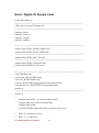
Note1: Digital I/O Sample Code
//File of the Main.cpp
//===========================================================
//This code is for test I570 Super I/O.
//===========================================================
#include <dos.h>
#include <conio.h>
#include <stdio.h>
#include <stdlib.h>
//============================================================
#define W83627EHG_INDEX_PORT 0x2E
#define W83627EHG_DATA_PORT 0x2F
//============================================================
#define W83627EHG_REG_LD 0x07
//============================================================
#define W83627EHG_UNLOCK 0x87
#define W83627EHG_LOCK 0xAA
//============================================================
void ClrKbBuf(void);
void Unlock_W83627EHG(void);
void Lock_W83627EHG(void);
void Set_W83627EHG_Reg(unsigned char,unsigned char);
unsigned char Get_W83627EHG_Reg(unsigned char);
int main ();
//============================================================
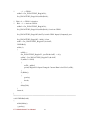
int main ()
{
unsigned char ucDO = 0; //data for digital output
unsigned char ucDI; //data for digital input
unsigned char ucBuf;
Set_W83627EHG_Reg(0x07,0x07);//switch to logic device 7
//
//
PIN 121~128 function select
Bit0 = 0 -> Game Port.
I771 Motherboard User Manual
80
//
= 1 -> GPIO1.
ucBuf = Get_W83627EHG_Reg(0x29);
Set_W83627EHG_Reg(0x29,ucBuf|0x01);
// Bit0 = 0 -> GPIO1 is inactive.
// Bit1 = 1 -> Activate GPIO1.
ucBuf = Get_W83627EHG_Reg(0x30);
Set_W83627EHG_Reg(0x30,ucBuf|0x01);//Activate GPIO1
Set_W83627EHG_Reg(0xF0,0x0F);//switch GPIO Input(1)/Output(0) port
Set_W83627EHG_Reg(0xF1, 0x00); //clear
ucDI = Get_W83627EHG_Reg(0xF1) & 0x0F;
ClrKbBuf();
while(1)
{
ucDO++;
Set_W83627EHG_Reg(0xF1, ((ucDO & 0x0F) << 4));
ucBuf = Get_W83627EHG_Reg(0xF1) & 0x0F;
if (ucBuf != ucDI)
{
ucDI = ucBuf;
printf("Digital I/O Input Changed. Current Data is 0x%X\n",ucDI);
}
if (kbhit())
{
getch();
break;
}
delay(500);
}
return 0;
}
//============================================================
void ClrKbBuf(void)
{
while(kbhit())
{ getch(); }
I771 Motherboard User Manual
81
}
//--------------------------------------------------------------------------void Unlock_W83627EHG (void)
{
outportb(W83627EHG_INDEX_PORT, W83627EHG_UNLOCK);
outportb(W83627EHG_INDEX_PORT, W83627EHG_UNLOCK);
}
//============================================================
void Lock_W83627EHG (void)
{
outportb(W83627EHG_INDEX_PORT, W83627EHG_LOCK);
}
//============================================================
void Set_W83627EHG_Reg( unsigned char REG, unsigned char DATA)
{
Unlock_W83627EHG();
outportb(W83627EHG_INDEX_PORT, REG);
outportb(W83627EHG_DATA_PORT, DATA);
Lock_W83627EHG();
}
//============================================================
unsigned char Get_W83627EHG_Reg( unsigned char REG)
{
unsigned char Result;
Unlock_W83627EHG();
outportb(W83627EHG_INDEX_PORT, REG);
Result = inportb(W83627EHG_DATA_PORT);
Lock_W83627EHG();
return Result;
}
//============================================================
I771 Motherboard User Manual
82
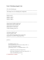
Note2: Watchdog Sample Code
//File of the Watchdog.cpp
//============================================================
//This Sample code is for Watchdog timer configuration
//============================================================
//============================================================
#include <dos.h>
#include <conio.h>
#include <stdio.h>
#include <stdlib.h>
//============================================================
#define W83627_INDEX_PORT 0x2E
#define W83627_DATA_PORT 0x2F
#define W83627_UNLOCK 0x87
#define W83627_LOCK 0xAA
//#define Watchdog_timeout 10
//============================================================
void Unlock_W83627(void);
void Lock_W83627(void);
void Set_W83627_Reg(unsigned char,unsigned char);
unsigned char Get_W83627_Reg(unsigned char);
//============================================================
int main ()
{
int Watchdog_timeout = 10;
printf("Input Watchdog Timer time-out value [0-255] : ");
scanf("%d",&Watchdog_timeout);
if(Watchdog_timeout <= 0 || Watchdog_timeout > 255)
{
printf("Time-out value out of range!!\n\n");
printf("Input Watchdog Timer time-out value [0-255] : ");
scanf("%d",&Watchdog_timeout);
I771 Motherboard User Manual
83
}
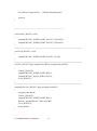
Set_W83627_Reg(0x07,0x08);//switch to logic device 8
Set_W83627_Reg(0x30,0x01);//Activate watchdog
Set_W83627_Reg(0xF5,0x06);//Select WDTO# count mode.Second Mode.
Set_W83627_Reg(0xF6,Watchdog_timeout); //Set Watch Dog Timer Time-out
value
//Set_W83627_Reg(0xF7,0xC0); //Clear Watchdog timer event
int i = Watchdog_timeout;
while(1)
{
if (kbhit())
{
if(getch()==0x1B) //Esc
break;
else{
i=Watchdog_timeout;
//Reset Watchdog timer
Set_W83627_Reg(0xF6,Watchdog_timeout); //Set Watch Dog
Timer Time-out value
}
}
clrscr();
if(i>0){
i--;
printf("After %2d sec reset computer!\n",i);
printf("Press any key to reset watchdog timer!\n");
printf("Press [Esc] to exit!\n");
}
else
printf("Watchdog timer fail!");
delay(1000);
}
I771 Motherboard User Manual
84
Set_W83627_Reg(0xF6,0); //Disable Watchdog timer
return 0;
}
//--------------------------------------------------------------------------void Unlock_W83627 (void)
{
outportb(W83627_INDEX_PORT, W83627_UNLOCK);
outportb(W83627_INDEX_PORT, W83627_UNLOCK);
}
//============================================================
void Lock_W83627 (void)
{
outportb(W83627_INDEX_PORT, W83627_LOCK);
}
//============================================================
void Set_W83627_Reg( unsigned char REG, unsigned char DATA)
{
Unlock_W83627();
outportb(W83627_INDEX_PORT, REG);
outportb(W83627_DATA_PORT, DATA);
Lock_W83627();
}
//============================================================
unsigned char Get_W83627_Reg( unsigned char REG)
{
unsigned char Result;
Unlock_W83627();
outportb(W83627_INDEX_PORT, REG);
Result = inportb(W83627_DATA_PORT);
Lock_W83627();
return Result;
}
I771 Motherboard User Manual
85