1
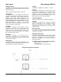
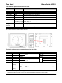
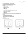
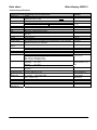
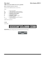
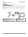
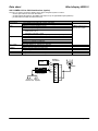
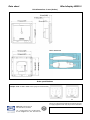
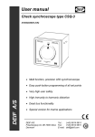
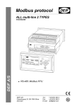
Wind display type WSDI-2 DATA SHEET Displays Watertight Relative or true wind speed and direction Wind speed in: m/s, knots or Beaufort Black base, white lines and figures 4-digit 7-segment red display Major class approvals, see homepage for certificates Housing Front 172 x 172, panel cutout according to size Q144 Robust design Shock: 100 g 11 ms Direct pointer illumination Trans-illumination of the scale by white LEDs Dimmer Approval According to IP66 from front Illumination Read-out Front or remote control of the light intensity Interface RS485 (NMEA 0183) wind sensor input Direct WSS sensor connection User interface Two push-buttons on the front allows the user to select wind speed units, control the light intensity and change settings Document no.: 4921250062C Data sheet Wind display WSDI-2 Displayed data Supply The DEIF wind indicator type WSDI-2 presents relative (apparent) or true wind data relative to ship on the high precision read-outs. The WSDI-2 is supplied from nominal 12…24V DC. NOTE: True wind requires the NCI-1 option box. Technology The WSDI-2 uses a centre-placed microprocessorcontrolled x-coil system for indication of the wind direction, combined with a 4-digit 7-segment display for indication of the wind speed. Compared to the traditional digital method, the clear advantage of this indicator principle, using an analogue pointer, is a more pedagogic presentation of the wind direction. This has been accomplished by means of the unique performance of the x-coil technology, well-known and proven in the DEIF XL instruments. Housing The WSDI-2 is designed for front mounting, using a standard cutout for size 144 combined with a front measure of 172 x 172 to give a clear read-out. The instrument is front mounted by means of four screws, one in each corner of the instrument. The screws are then covered by the front frame. Pointer The WSDI-2 is equipped with a pointer made by light guide material and shaped as a needle pointer. Compared to traditional read-out based on LEDs arranged in a circle, the illumination method of the pointer makes the read-out extremely easy, even at longer distances and also in bright sunlight. Pointer deflection The pointer is able to move 360 degrees (endlessly). Display The WSDI-2 is equipped with a red 4-digit 7-segment display. The intensity can be controlled in steps to match the actual situation, and in addition, a “bright sunlight step” can be selected to provide easy read-out in bright sunlight. Error function The WSDI-2 is equipped with a triangular LED located in the lower left corner of the display. This LED will flash if the unit is out of order. Operation and setup Interface The WSDI-2 connects to any sensor with an RS422/485 communication port with NMEA 0183 protocol. DEIF wind sensor type WSS can be directly connected to the WSDI-2. Illumination The WSDI-2 has direct yellow pointer illumination. The scale base is black, and the figures and lines are white and illuminated from behind by white LEDs. The WSDI-2 is equipped with two push-buttons located on the front. These push-buttons are used to set up the read-out on the display – m/s, knots, Beaufort. In addition, the push-buttons can be used to control the illumination intensity. Available sensors, accessory and options - WSS or WSS-L static wind sensor - IP66 rear cover - NCI-1 NMEA 0183 to CAN interface box Single line application diagram DEIF A/S Page 2 of 9 Data sheet Wind display WSDI-2 User interface - push-buttons on front side Type 1. Status LED 2. Status LED 3. Status LED 4. Status LED 5. Status LED 6. Error LED Function M/S KTS BEAU REL TRUE ERROR Remark Indicates selection of wind speed read-out in m/s Indicates selection of wind speed read-out in knots Indicates selection of wind speed read-out in Beaufort Indicates selection of wind values relative to ship Indicates selection of true wind values Indicates internal error (orange flash) 7. Status LED 8. Status LED Service tool Service tool See error functions section in User's Manual/Installation Note 7-segment display Wind speed/ information (4-digit) Guides the user in the menu system and provides information about dimmer levels, setup, etc. Analogue scale and pointer 1. Push-button 2. Push-button Wind direction 360 degrees pointer rotation on a black back illuminated scale MODE Dimmer Selects operation and setup modes Selects dimmer level and provides enter function @: All status LEDs and 7-segment displays are red. Terminals and function - connector located on rear side Terminal no. 1 Signal 0V Marking 1.- 2 12/24 V 3 4 CAN-H Dimmer (CAN-C) Dimmer or CAN-L Not used RS485 (Data+) RS485-GND 2. +12/24 V 3. 4.Dim-sw 5 6 7 8 9 1) RS485 (Data-) Remark Aux. supply, 9.0…31.2V DC, <5 W In addition, connect WSS1) and NCI-1 black wire 1) In addition, connect WSS and NCI-1 red wire CAN-H on the NCI-1 Do not connect to NCI-1 OR CAN-L on the NCI-1 5.Dim-sw Do not connect Connect to a potential free contact. Open 2.5 V, closed 0.1 mA 6. 7.A (+) Do not connect Connect to orange wire on WSS 8. Data GND 9.B (-) Normally not connected, can be connected to screen on WSS to suppress EMC Connect to brown wire on WSS If the wind sensor is type WSS, the supply must be able to provide 12 V/24V DC/2A. If the sensor is type WSS-L, the supply must be able to provide 12 V/24V DC/0.6A. See the WSS documentation for more details. DEIF A/S Page 3 of 9 Data sheet Wind display WSDI-2 User menu Two push-buttons, “MODE” and “☼”, control the user interface. The following can be set/selected using the setup and the select key: Daily menu: Wind speed type (M/S, KNOTS, BEAUFORT) Dimmer level (0-9) Advanced menu: Wind type (relative or true) Damping (1, 5, 10 or 30 seconds) Beep (on, off) Light group (0-6, none) Installation menu: Input type (NMEA 0183, NMEA 0183+remote dimmer, CAN, Demo) Light mode (L1, L2) Offset correction (±180 degrees) Service tool Source reset For further information about the menu structure, please see the User’s Manual/Installation Note. Versions WSDI-2 FWD, for mounting on forward bridge Ship’s bow and scale value zero are located at 12 o’clock. WSDI-2 AFT, for mounting on aft bridge Ship’s bow and scale value zero are located at 6 o’clock. Scale designs There are two types: FWD (forward) and AFT. Please notice the inverted pointer on the AFT version. Both types are shown with identical input signal. DEIF A/S Page 4 of 9 Data sheet Wind display WSDI-2 Technical specifications Indicators are designed according to the standards below Sensor input RS485 Accuracy Analogue instrument (wind direction) class 0.5 (-10…15…30…55C) Digital instrument ±1 digit Response time Analogue instrument 90° per sec./no overshoot Instrument size Panel cutout Front 136 x 136 mm 172 x 172 mm Aux. supply 12/24 V (9.0…31.2V DC), <5 W Remote dimmer Potential free contact. Open 2.5 V, closed 0.1 mA Galvanic separation 500 V between groups (RS485, PSU, remote dimmer/CAN) Scale Black base, white figures and lines Pointer Transparent polycarbonate with white print and yellow illumination (588 nm) Window Antiglare 2 mm Acrylic (UV-resistant) Housing ASA-PC blend Connections Screw terminals: 2.5 mm2 (multi-stranded), 4 mm2 (single-stranded) Mounting angle The indicator can be mounted at any angle between 0...150° horizontal without this affecting the calibration Compass safety <0.2 m distance Communication RS485 interface and NMEA 0183 MWV sentence Proprietary CAN for use with NCI-1 NMEA to CAN interface box Out of range Flashing orange LED Protection From front IP66, from rear IP20/IP66 when using IP66 rear cover option Climate Class H S E, short-term condensing allowed Max. 95% RH: Max. 30 days per year Max. 85% RH: Remaining days Max. 75% RH: Average per year Temperature Nominal: -10…55°C Operating: -25…70°C Storage: -40…80°C Influence: Max. ±1.5% within -15...55°C Panel influence The accuracy is affected neither by the material nor by the thickness of the panel Panel thickness No limit Mechanical shock 18 x 50 g half sine (11 ms) test Vibration test 3…13.2 Hz: 2 mm (peak-peak) 13.2…100 Hz: 0.7 g Safety 300 V – Cat. III. Pollution deg. 2 EMC CE-marked for industrial environment Weight 0.55 kg Dimensions, 220 x 200 x 100 mm cardboard box DEIF A/S Standards IEC/EN 60051 DIN 43700 for panel cutout only UL94 V0 DIN 16257 IEC/EN 60945 NMEA 0183 ver. 2.x-3.0 IEC/EN 60529 IEC/EN 60068-2-30 Max. 97% RH IEC/EN 60068-2-1 Cold IEC/EN 60068-2-1 Dry heat IEC/EN 60051 IEC/EN 60068-2-27 IEC/EN 60945 DNV Class A IEC/EN 61010-1 IEC/EN 60945 Page 5 of 9 Data sheet Wind display WSDI-2 NMEA 0183 used in DEIF wind sensor type WSS MWV, wind speed and direction response: Sentence format: $WIMWV,296,R,9.7,N,A*20<cr><lf> where $ WI MWV 296 R 9.7 N A * 20 <cr><lf> = = = = = = = = = = = Start of the message Talker identifier (WI = weather instrument) Wind speed and direction response identifier Wind direction value (degrees) Wind direction unit (R = relative) Wind speed value (knots) Wind speed unit (knots) Data status: A = valid, V = invalid Check sum delimiter Two-character check sum for the response Response terminator Update rate: Every second. Labels Product label: DEIF WSDI-2 wind display Bar code + item number CE logo Made in Denmark Logo DEIF logo Warranty label: Placed over the centre mounting screw on the rear side (below the product label). DEIF A/S Page 6 of 9 Data sheet Wind display WSDI-2 System connection with DEIF WSS sensor RS485 (I/O) operation: The bus should be terminated with 120 Ohm for pure RS485 operation. Combined RS485 (I/O) and NMEA 0183 (I) operation: A combination of up to ten RS485 (I/O) and one NMEA 0183 listeners can be connected to the WSS data interface at the same time. The data line must be terminated with a 200 to 250 Ohm resistor to obtain > +/- 2.1 V output necessary for a standard NMEA 0183 input circuit to work (a 200 Ohm resistor is included in the WSDI-2 package). The NMEA 0183 input load must be < 2 mA @ +/- 2 V. NOTE: The NCI-1 option box or a NMEA-buffer is recommended if connection of more than one standard NMEA input is needed. DC power source + WSDI-2 1. 2. …. 7. 8. 9. Conn. kit (Optional) T IMPORTANT! The stainless steel mounting base on the WSS/WSS-L must be connected to the ship's metal hull or another good ground connection! DEIF A/S IMPORTANT! The data bus must be terminated with a resistor (see technical spec. above) to secure stable operation! Page 7 of 9 Data sheet Wind display WSDI-2 NCI-1 NMEA 0183 to CAN interface box (option) The NCI-1 is used to connect the WSDI-2 to the ship’s navigation system in order to: - receive speed data for true wind calculations - provide buffered wind data on the NMEA 0183 output for up to eight NMEA inputs (listeners) - provide MWV and VWR wind data sentences Option: NCI-1 NMEA 0183 to CAN interface box Connections 1.5 m NMEA 0183 cable with 4 wires and shield 1.5 m CAN cable with 2 CAN wires, 2 aux. supply wires and shield Input NMEA 0183 opto-insulated (1.5 kV) Differential input voltage min. 1.8 V Max. input voltage: Continuous +/-15 V Less than 1 second: +/-35 V Receiving sentence: VHW (water speed) or RMC, VTG (COG) Output NMEA 0183/RS422 insulated (1.5 kV) from aux. supply and CAN Output current max. 20 mA Output voltage min. 2.1 V @ 100 Ohm load Drives up to 8 NMEA 0183 inputs Transmitting sentences: MWV and VWR Aux. supply Nominal voltage 12…24V DC (8…35V DC) Consumption max. 0.8 W @ full load on data channel CANbus Built-in network terminator (120 Ohm) Proprietary protocol Environment Same as for the WSDI-2 display unit Size Length 179 mm, width 46 mm, height 28.5 mm DC power source + NMEA out NMEA in DEIF A/S WSS CAN No connection to/from nav. system NMEA 0183 ver.2.x-3 IEC 61162-1:2000 WSDI-2 connector 1 2 3 NCI-1 NMEA Standards (4) 5 6 7 8 9 Page 8 of 9 Data sheet Wind display WSDI-2 Unit dimensions in mm (inches) NCI-1 dimensions Order specifications Example: WSDI-2 FWD or WSDI-2 AFT (only two versions exist) Due to our continuous development we reserve the right to supply equipment which may vary from the described. DEIF A/S, Frisenborgvej 33 DK-7800 Skive, Denmark Tel.: +45 9614 9614, Fax: +45 9614 9615 E-mail: [email protected], URL: www.deif.com