1
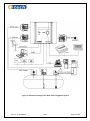
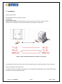
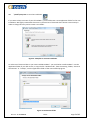
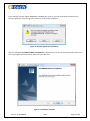
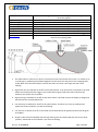
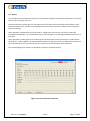
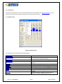
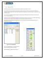
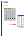
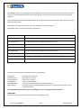
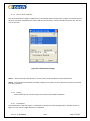
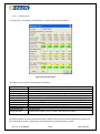
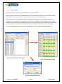
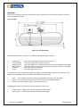
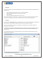
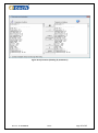
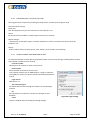
FuelWin® Wet stock monitoring software INSTALLATION AND USERS MANUAL Doc.no. 15-SFW08043 - Rev A CONTENTS 1. Introduction ............................................................................................................................... 4 1.1. Basic components in a complete system ...............................................................................................................................5 2. Installation ................................................................................................................................. 7 3. Start FuelWin®.......................................................................................................................... 10 3.1. Command options ................................................................................................................................................................10 3.2. Run FuelWin .........................................................................................................................................................................11 3.3. Program setup......................................................................................................................................................................12 3.3.1. Direct rs232 data cable communication ........................................................................................................................12 3.3.2. Report setup...................................................................................................................................................................12 3.3.3. History setup ..................................................................................................................................................................12 4. System overview ....................................................................................................................... 13 4.1. Status bar / Panel .................................................................................................................................................................15 4.1.1. Icons: ..............................................................................................................................................................................15 4.2. Alarm description .................................................................................................................................................................16 4.2.1. High Alarm......................................................................................................................................................................16 4.2.2. Low Alarm ......................................................................................................................................................................16 4.2.3. High Warning .................................................................................................................................................................16 4.2.4. Low Warning ..................................................................................................................................................................16 4.2.5. Leakage Alarm (static leak detection) ............................................................................................................................16 4.2.6. Deviation Alarm (dynamic leak detection) .....................................................................................................................16 4.2.7. Water height ..................................................................................................................................................................16 4.2.8. System Alarm .................................................................................................................................................................16 4.3. Alarms ..................................................................................................................................................................................17 4.4. Tool tips ...............................................................................................................................................................................18 5. Menus ..................................................................................................................................... 19 5.1. File........................................................................................................................................................................................19 5.1.1. Print ................................................................................................................................................................................20 5.1.2. External Connection .......................................................................................................................................................20 5.1.3. Backup ............................................................................................................................................................................21 5.1.4. Printer Setup ..................................................................................................................................................................21 5.1.5. Language ........................................................................................................................................................................21 5.1.6. Connect ..........................................................................................................................................................................21 5.1.7. Exit..................................................................................................................................................................................21 5.2. View menu ...........................................................................................................................................................................22 5.3. Reports menu ......................................................................................................................................................................22 5.3.1. Delivery report ...............................................................................................................................................................23 5.3.2. Leakage report ...............................................................................................................................................................25 5.3.3. How to start a leak test ..................................................................................................................................................27 5.3.4. History ............................................................................................................................................................................27 5.3.5. Leak details.....................................................................................................................................................................27 5.3.6. Volume report ................................................................................................................................................................28 5.3.7. Period Report .................................................................................................................................................................29 5.3.8. History ............................................................................................................................................................................30 5.3.9. Alarm history ..................................................................................................................................................................31 5.3.10. Error log .........................................................................................................................................................................31 5.3.11. Alarm ..............................................................................................................................................................................31 5.3.12. Service log<Password protected> ..................................................................................................................................32 5.3.13. Real time ........................................................................................................................................................................32 5.4. SETUP MENU........................................................................................................................................................................33 5.4.1. Buzzer off .......................................................................................................................................................................33 5.4.2. Reset alarms ...................................................................................................................................................................33 5.4.3. Reboot /Restart <Password protected> .........................................................................................................................33 5.4.4. Alarm setup ....................................................................................................................................................................34 5.4.5. Tank setup <Password protected> ................................................................................................................................36 Doc.no. 15-SFW08043 Rev A Page 2 of 48 5.4.6. 5.4.7. 5.4.8. 5.4.9. 5.4.10. 5.4.11. 5.4.12. PROGRAM SETUP <Password protected> ......................................................................................................................41 LOGIN SETTINGS <PASSWORD PROTECTED> .................................................................................................................41 POS PROTOCOL SETTINGS <PASSWORD PROTECTED>...................................................................................................42 GAUGE TABLES ...............................................................................................................................................................43 CALIBRATION <Password protected> .............................................................................................................................44 Site information .............................................................................................................................................................45 System time....................................................................................................................................................................46 5.5. Help menu............................................................................................................................................................................47 5.5.1. User manual ...................................................................................................................................................................47 5.5.2. ABOUT 4TECH.................................................................................................................................................................47 6. Troubleshooting ....................................................................................................................... 48 Doc.no. 15-SFW08043 Rev A Page 3 of 48 1. Introduction 4tech AS has taken advanced technology in use, to give the user a high performance solution designed to meet all of your environmental and inventory management needs, both at present and in the future. 4tech has over the last 10 years developed a powerful wet stock monitoring and reconciliation software package for personal computers. FuelWin® uses the 4tech FIP protocol in its full extent to provide the user with the important information collected by the control unit, FuelCom® 5080. FuelWin® acts as a control centre where the complete system can be set up for integration and communication. FuelWin® gives you an overview of level, temperature and alarm status on each tank. The level and temperature is stored and time stamped every hour. FuelWin® collects reports for deliveries, calculated sales and leakages. Full benefit with pump traffic included in reports, when connected to supported Point of Sales Systems. Analysis can be performed with the real time log function, logging the level of each hour. 4tech AS offer a complete range of gauging devices by using patented high performance sensors and advanced control units for domestic market (heating oil), the industrial market, lubricants, chemicals and petrol stations. The data can be displayed locally by the FuelWin program or through one of the supported Point of Sale Systems. Information registered by the different devices can also be collected, processed and exchanged over the internet. 4tech offers notifications regarding alarms and level on SMS, E-mail and even interfaces with ERP systems through either FTP or VPN services. Doc.no. 15-SFW08043 Rev A Page 4 of 48 1.1. Basic components in a complete system FuelWin® FuelWin® is the software package optionally delivered with the FuelCom® 5080 controller. It is both the setup tool for installers and acts as an independent wet stock monitoring system. FuelCom® 5080 The FuelCom® 5080 is the control unit which manages the probe signals and calculates the liquid height and level based on the measurements of the pressure and temperature inside the tank. It can be connected directly to the FuelWin® wet stock management system, and can also be equipped with GSM modem, TCP IP adapter, in addition to its built in modem for remote control and server communication. AD 424 The AD424 module is a 4 channel intrinsically safe galvanic isolated input module for FuelCom® with 4-20 mA current loops. The module is compatible with FuelBar®, MiniBar probes and various 3rd party of 4-20 mA equipment (E.g. Level Flex from Endress & Hauser). One module can be connected to 2 FuelBar® or MiniBar probes. FuelBar® 410 and MiniBar probes The FuelBar® 410 is used for measuring level (pressure), temperature and water. It has a reed relay which triggers when the floater rise about 25 mm. This is an on/off signal, which uses the temperature loop. The MiniBar probe is for measuring level (pressure). Each tank must be equipped with one probe. The signal from each probe is proportional to the level measurements; these signals are scanned and interpreted by the FuelCom® unit. The volumes are calculated and presented in volume and normal litres (Temperature compensated); furthermore the unit performs alarm checking, delivery detection, leakage detection and handles communication to other devices. The FuelCom® unit has capacity to store 3 delivery reports, 6 period reports and one leakage report pr. tank. The FuelWin® program gather the reports and store them in a local database. This manual describes the wet stock monitoring software FuelWin®. IMPORTANT: It is important that the system is checked on a regular basis. This is especially important after installation to ensure that the system is correctly calibrated. Differences between measured volume and sold volume should be monitored closely the first few weeks. Doc.no. 15-SFW08043 Rev A Page 5 of 48 Figure 1: Schematic drawing of the 4tech tank management system Doc.no. 15-SFW08043 Rev A Page 6 of 48 2. Installation System requirements: PC with Windows 98, NT, 2000, XP or Vista; 64 Mb RAM; 20 Mb free disk space; Serial COM port connection (USB to RS232 converter) from PC to modem or FuelCom® unit; FuelCom® unit installed for connection with GSM, TCP IP adapter or serial cable. Figure 2: Serial connection between the FuelCom® unit and PC. You should ensure that your user account has the required rights to install the software on the computer. Read last changes in the release notes. If FuelWin® already is installed on the computer; you should backup the database file “4tech32.mdb” which is located in the 4tech application folder. Doc.no. 15-SFW08043 Rev A Page 7 of 48 Run \install\setup.exe to start the installation. If you want to keep a version of your old FuelWin®, you should create a new application folder for the new installation. We highly recommend this action to prevent loss of historical data. Choose custom setup in order to change directory and to create a new folder. Figure 3: Complete or custom installation To make use of historical data in your new installed FuelWin® you could either install FuelWin® into the application folder of your old version, or copy the file “4tech32.mdb”, from the existing folders, “External Connections” or “backup”, into the application folder of the new installed program. Figure 4: Destination folder Doc.no. 15-SFW08043 Rev A Page 8 of 48 If the message “Cannot register RDO20.dll or DAO350.dll” pops up, it means that these components are already registered. Press the <Ignore>-button to continue the installation. Figure 5: Already registered components After the message “InstallShield Wizard Completed” is displayed on the screen, click Finish and a short cut to start the program should have been placed on your desk top. Figure 6: Installation complete Doc.no. 15-SFW08043 Rev A Page 9 of 48 3. Start FuelWin® To start FuelWin® in the desired mode you should define the command option in the target line which is located in the application shortcut target field. Right click on the shortcut to FuelWin®, and select Properties, and a “Properties” window (as shown in Figure 7) will open. 3.1. Command options %app.path%\4tech32.exe –c –nks –modem –small –large –lang –test -xoff –sim -demo -compartment Displays compartment name instead of Tank number (alt. “-c”). -nks Ensure that reports remain in the FuelCom® unit until they are read and deleted by the 4tech NKS system. -modem FuelWin® is to be used for External connection. -small Force FuelWin® to believe there are only tanks under 65,000 litres (normally not in use). -large Force FuelWin® to believe there are tanks over 65,000 litres. -lang Add index number to language dependent text strings (provided as a tool for translators, normally not in use). -test Open a communication debugger window (provided as a tool for FuelCom® integrators, normally not in use). -xoff Disables the Close button in all FuelWin® windows to avoid unwanted close downs (alt. “-nox”). Figure 7: Properties Doc.no. 15-SFW08043 Rev A Page 10 of 48 3.2. Run FuelWin Click on the 4tech shortcut on your desktop or use the 4tech.exe file, which is located at C:\Programfiler\4tech\FuelWin\ or C:\Program files\4tech\FuelWin\ to run FuelWin® If the window as shown in Figure 8 appears, it means that the parameters in the FuelWin® database (Microsoft Access Database) and in the FuelCom® unit are different from each other. You can synchronize the data by clicking the “Yes” button or choose “synchronize” in tank setup. Password is: india Note! Take special care not to synchronize the wrong way between the software and the FuelCom® 5080. This may cause resetting an already programmed controller to default or faulty values. Data is usually collected from the gauge and to the computer/database before changes are made. Figure 8: FuelWin® connect We recommend and appreciate that you use the Service log to write down all changes, parameters and services. It can be very helpful for you, other technicians and our support department to see the changes done in the configuration or site. IMPORTANT: If the message “Comm. failure with FuelCom® unit” is shown, the PC and the FuelCom® unit do not communicate. Check that cable is ok and connected and if the devices still don’t communicate, try another COM port, please read section 5.4.7. Program setup for more details. You have to choose Connect on the File menu between each attempt. If the system still does not communicate, contact your dealer for technical support. Doc.no. 15-SFW08043 Rev A Page 11 of 48 3.3. Program setup 3.3.1. Direct rs232 data cable communication Unless the cable between the computer and the gauge is inserted in COM-port 1 (default value in FuelWin®), you will have to open Program setup and choose the communication banner (Figure 9) in order to set the correct COM-port for communication. You can use the scan button to find any available ports on your computer. 3.3.2. Report setup The Report banner (Figure 10) allows the user to either select or deselect the collection of delivery, period and leakage reports. It also sets the poll interval which controls communication interval between FuelWin® and the FuelCom® 5080 controller. The controller itself collects probe readings every 10 seconds and intervals shorter than this would be needless. 3.3.3. History setup In the history setup (Figure 11) you can choose for how long to keep history for each report type, default is set to 365 days. Figure 9: Communication Figure 10: Reports Figure 11: History Doc.no. 15-SFW08043 Rev A Page 12 of 48 4. System overview Figure 12: System overview The FuelWin® system overview contains the following information: Tank num / Compartment Product Label volume Max Fill Limit Volume indicator Volume Ullage Alarms and warnings: Doc.no. 15-SFW08043 Tank number 1 to 8. Product quality: 95 unleaded, 98 unleaded, 98 leaded… (In short format) Total tank capacity in litres. The desired filling limit to which the tank is to be filled controlled by the “High warning *%+” Graphical indication of product level Current tank volume in volume litres at given temperature. Difference between volume at high warning level and current tank volume, i.e., the empty space available to be filled up. All alarms are indicated with red colour and a beeping sound when they appear. Rev A Page 13 of 48 High Alarm (HA) High Warning (HW) Low Warning (LW) Low Alarm (LA) Leakage Alarm Deviation Alarm Water Alarm System Alarm All warnings are indicated with orange colour and a single beep when they appear. Alarm limit in % of the label volume. Graphical alarm indication. Warning limit in % of the label volume. Graphical alarm indication. Warning limit in % of the label volume. Graphical alarm indication. Alarm limit in % of the label volume. Graphical alarm indication. Graphical indication if leakage test detects positive or negative leak. Detects if the calculated sales differ from the pump sale. Graphical indication If the floater on the FuelBar has raised and triggered. Graphical indication if there is no communication with the A424 module or faults in the strapping table. _HELP_MENU Figure 13: Tank details and abbreviations 1. The label volume is often set to what is assumed to be the total volume of the tank. It is usually set to a round figure, symbolizing the labelled signboard on the tank. The end point of the strapping chart, usually differ from the label volume, because the tanks tend to be a bit larger than the actual marking. 2. High alarm limit is as default set at 95% of the Label volume. It can be used to correspond to the level where the overfill prevention trigger. The red LED will be ignited and alarm will sound from the FuelCom® unit and/or the pc speaker. 3. High warning is as default set at 90% of the Label volume. This field controls the display of ullage (the safe amount that could be delivered). 4. Low warning is as default set at 10% of the Label volume, and often act as the re-ordering limit. Yellow LED on the FuelCom® unit will start flashing. 5. Low alarm is as default set at 5% of the Label volume. Red LED will be ignited and alarm will be given in FuelWin®. 6. Ullage is Label volume multiplied with the high warning limit and subtracted with the current level (volume). Yellow LED on the FuelCom® unit will start flashing. Doc.no. 15-SFW08043 Rev A Page 14 of 48 4.1. Status bar / Panel 4.1.1. Icons: Communication with the FuelCom® unit is established and working. Indicate communication with the FuelCom® each time FuelWin® polls the controller. Communication with the FuelCom® unit is not established. New Period report is received from the FuelCom® unit. Double click on the icon to view the report. Indicate that a new sales report is received and still unread. New Delivery report is received from the FuelCom® unit. Double click on the icon to view the report. Alarm triangle, red blinking if any internal or external alarm is active. Double click on the icon to view the active alarm(s). Leakage test in progress (double click to see progress) All possible external alarms are inactive. One ore more external alarms are active. Push button to view External alarms. New Leak report is received from the FuelCom® unit. Double click on the icon to view the report. Doc.no. 15-SFW08043 Rev A Page 15 of 48 4.2. Alarm description 4.2.1. High Alarm This alarm is generated if measured level is above entered high alarm limit. This limit can be adjusted in the Alarm Setup window. To avoid that the alarm results from the sudden level changes during the delivery, the high alarm can be time delayed by setting the desired delay time in minutes in the Alarm Setup window. It is also possible to disable the High Alarm in this window. 4.2.2. Low Alarm This alarm is generated if measured level is below the entered low alarm limit. This limit can be adjusted in the Alarm Setup window. This alarm will generate relay output to trig on the specified events. 4.2.3. High Warning This warning is generated if measured level is over the entered high warning limit. This limit can be adjusted in the Alarm Setup window. 4.2.4. Low Warning This warning is generated if measured level is below the entered warning limit. This limit can be adjusted in the Alarm Setup window. It is usually set as the ordering level. 4.2.5. Leakage Alarm (static leak detection) Alarm is given if the measured leakage is more than the accepted tolerance. This alarm is only given as a result of a performed leakage test. See document describing leakage detection. 4.2.6. Deviation Alarm (dynamic leak detection) There are some other reasons to results in a deviation between measured volume and sold volume. Tolerance alarm is given if the deviation exceeds the limit entered in the Alarm Setup window. This alarm depends on communication between the POS System and the FuelCom® unit. If no communication is established between the two devices, this alarm can be disabled in the Alarm Setup window. 4.2.7. Water height Water alarm is given if the water level is exceeding approximately 25 mm with FuelBar® with plastic foot and 45 mm with FuelBar® with anchor. Water height is measured at the probe installation point. 4.2.8. System Alarm The FuelCom® unit performs a self test every 10th minute. If there are logical errors in gauge tables or sensors are behaving odd, an alarm is given. The FuelCom® unit will display an alarm type number (reference to FuelCom® technical manual). IMPORTANT: Not all of the alarms have automatic reset. Critical alarms like leakage alarm will be active until the user selects Reset Alarm in the Setup menu. This function is made to force the user to take notice of the alarm. Doc.no. 15-SFW08043 Rev A Page 16 of 48 4.3. Alarms To view both internal and external alarms, press the Alarm triangle or press Reports and Alarms in the drop down list in the system overview. The External alarms window give you the opportunity to monitor the oil interceptor and to detect a leak inside interstitial space, a well or a sump (Require external sensors connection. Please refer to FuelCom® technical manual). Alarm group #1 is dedicated to the oil interceptor. A high alarm tells you that you have to empty the interceptor immediately. If an overfill alarm occurs, the interceptor is overflowing. Immediate action has to be taken! Alarm group #2 is covering alarms for monitoring of interstitial spaces, wells and sumps. If a hydrocarbon alarm occurs, a leak of gasoline or diesel has been detected. A high alarm tells you if liquid has entered into the interstitial space, and a low alarm tells you if liquid from interstitial space have dissipated. The corresponding input number can be found in FuelCom® technical manual. Figure 14: Internal and external alarms Doc.no. 15-SFW08043 Rev A Page 17 of 48 4.4. Tool tips The text in the yellow box which appears when the mouse cursor moves over a text or field is called a “Tool tip”. As shown in the Figure 15, an example is displayed. (1) The product type fields will shorten the product name to seven characters, but the Tool tip of the product type fields can display the product name in its full length. 2) The tool tip for Ullage displays the formula for Ullage. Note that Ullage is not the tanks total capacity minus the current volume. Ullage is defined as the max fill limit (volume at high-warning level) minus the current volume. (3) Tool tip for the communication status field at the status panel shows the full path of active program database. Figure 15:“Tool Tips” displayed on window Doc.no. 15-SFW08043 Rev A Page 18 of 48 5. Menus The menu line contains the following options: File Action bar pull-down shows sub-menus such as Print, Exit etc. View Action bar pull-down shows the selected features in the System overview. Reports Action bar pull-down shows all available types of reports and logs. Setup Action bar pull-down shows all available setting forms. Help Action bar pull-down shows sub-menus: “About 4tech …” 5.1. File The file menu contains the following options: Print Print a report containing all the information in the main Information window. Ext. connection Connection to a remote FuelCom® unit using a modem or adapter. Backup Function for safety backup of the FuelWin® database. Printer setup Link to Windows printer setup functionality. Language Select desired language. Connect Re-connect the PC to the FuelCom® unit if communication fails. Figure 16: File menu Exit Close FuelWin® software. Doc.no. 15-SFW08043 Rev A Page 19 of 48 5.1.1. Print By choosing this option all information in the system overview is written to the default printer connected to the PC. 5.1.2. External Connection Remote connection to the FuelCom® unit can be made by using the External Connections located in the file menu. To do this you need an analogue, GSM or TCP IP modem connected to the PC running FuelWin®. Step 1. Connect the FuelCom® unit to an analog telephone line: Connect the FuelCom® unit to a telephone line which is not already used by other equipment such as fax, burglar alarm etc. If only ISDN is available, an ISDN – Analogue converter can be installed, or an external ISDN modem may be used. A GSM modem (SIEMENS TC 35) or TCP IP adapter (IRIS 800, SARIAN Router) can be used as well. Please refer to related technical documents for details. Step 2. Start FuelWin® for External Connection: To start FuelWin® for External Connection the program has to be started with the “-modem” option. Click on the 4tech short cut icon with the right mouse button. Choose Properties and Shortcut. Write “–modem” and “–nks” after the text in the path: “c:\program files\4tech\FuelWin\4tech32.exe” – modem –nks. This will enable the possibility for remote communication and prevent FuelWin® from acknowledge reports that still haven’t been read by the central server. This allows both systems to read the information. Choose OK. Connect the modem to the PC’s communication port. Start FuelWin®. Select serial port in the program setup menu. Choose External Connection. As seen in the Figure 17 , select New to make a new connection. Type the Device name of the external site. Type the Phone number or IP address you wish to connect to. Insert the modem initial command (i.e., AT&F). Create a new or select the existing database. Select save to store the information. Doc.no. 15-SFW08043 Rev A Figure 17: FuelWin® Dial window. Page 20 of 48 View offline View data for the selected external unit without being connected to FuelCom® unit. Connect Dial the selected external unit. Close Closes the Dial window. After you have entered this information you choose Connect, the system dials the external device. If everything is correctly set the two modems will establish connection. The text Connect will change to Disconnect and the data in the FuelCom® unit will be transferred to FuelWin®. To exit the program, click on Disconnect, choose Close in the Dial window, and then choose exit on the File menu. IMPORTANT: The modem used must be standard modem (Hayes compatible). If you get problems configuring the modem or getting the system to communicate, contact your dealer for help. 5.1.3. Backup Make a safety backup of the FuelWin® database. FuelWin® automatically suggests a filename as <today’s date.mdb>. 5.1.4. Printer Setup This function calls the standard Windows printer setup functionality. See the Windows manual for further description of how to choose and set up your printer. 5.1.5. Language All text in the windows, menus and reports are enabled in several languages. Select desired language in the language menu. Default language is English. 5.1.6. Connect If the communication between FuelWin® software and FuelCom® unit for some reason should fail (mains failure, cable failure, etc.), the communication is established again by selecting Connect. Note! Data shown by the FuelWin® software is not correct if the communication has failed. Off-line mode is entered and the last data read will be kept in the memory. 5.1.7. Exit Exit the FuelWin® software. Doc.no. 15-SFW08043 Rev A Page 21 of 48 5.2. View menu The view menu allows the user to select which features to be included in the System overview. You can choose to view only the bar graphs, volume or any combination in the list. 5.3. Reports menu Figure 18: Report menu The “Reports” menu contains the following options: Delivery report Leakage report Volume report Periodic report Alarm log Error log Service log Alarms History Real time Doc.no. 15-SFW08043 Information about detected deliveries. Function for starting a new leakage test or viewing the result of the latest leakage tests. Detailed volume analysis concerning tank inventory. Detailed volume and sale analysis trough selectable period. Contains listing of the latest 250 alarms. Log of errors detected within the program Service function for service data logging. Alarm information (Internal and external) Optional historical data logged the latest three months. A powerful tool for logging AD values, product height, and volume continuously to a file. Rev A Page 22 of 48 5.3.1. Delivery report The delivery report is opened by choosing Delivery Report on the Reports menu The system automatically detects new deliveries. When a delivery is detected all values are read by the FuelWin® software and stored in the system database. The deliveries are shown with date, tank number and received volume. It is possible to find specific deliveries within a time period by inserting the wanted dates in the From/To boxes and then click Find. The delivery report is generated by triggering start point and detection of end point. To ensure a high quality delivery report, the report has a time-delay of 25 minutes after end point detection. New deliveries are notified by showing a small icon on the status line. By double clicking this icon new deliveries will be shown. Figure 19: List of deliveries You can by highlighting one to eight deliveries open the reports in the same window. Figure 20 displays a typical delivery report. Figure 20: Typical delivery Doc.no. 15-SFW08043 Rev A Page 23 of 48 The delivery report contains the following information: Tank number - The displayed tank number. Product type - 95 Unleaded, 98 Unleaded, 98 Leaded… Label volume - Total tank capacity in litres. Date - Delivery date. Start volume - Volume in volume litres at delivery start. Start volume TC - Volume in normal litres at start of delivery (Temperature Compensated). Start temperature - Product temperature in degrees Celsius at delivery start. End volume - Volume in volume litres at end of delivery. End volume TC - Volume in normal litres at delivery end (Temperature Compensated). End temperature - Product temperature in degrees Celsius at delivery end. Delivered volume - Number of volume litres delivered. Delivered volume TC - Number of normal litres delivered (Temperature Compensated). Pump sales - Volume litres sold during the delivery (only if interfaced to POS). Dev. Delivery - The deviation between delivered and sold volume (only if interfaced to POS). IMPORTANT: In order to store all new delivery reports in the local database, FuelWin® should be running on a PC connected to FuelCom® unit at all times. Refer also to period report for summarised delivery reports. Gasoline and diesel products are sold at a set temperature. This temperature is set by authorities in each country. 15 degrees Celsius is used in FuelWin® software for temperature compensation. Doc.no. 15-SFW08043 Rev A Page 24 of 48 5.3.2. Leakage report The leakage reports are opened by clicking on Reports, and then choose Leakage report. Figure 21: Leakage report Figure 22: Leak details Doc.no. 15-SFW08043 Rev A Page 25 of 48 The leakage- report/ -test averages the level (height) measurements during the interval of 10 minutes. These values are presented graphically with bars and analysed. The values are also stored in password protected database. The horizontal axis presents the height difference. The vertical axis presents the time. The start time is at the top of the vertical axis. The fields of “Leakage” and “status” give the conclusions of the leak analysis. The leakage report contains the following information: Tank number - The displayed tank number. Start volume TC - Volume in litres at start of test. (Temperature compensated). Start temperature - Product temperature in degrees Celsius at test start. Start time - Date and time at start of test. Graphical leakage - Graphical presentation of leakage in mm/10 minuets. End temperature - Product temperature in degrees Celsius at end of test. End time - Date and time at end of test. Leakage - Leakage given in litres/hour. Status - Shows the conclusions of the leak report. Statuses (see leak detection document for more information): OK (green) Deviation (red) Testing (yellow) Invalid (blue) Cancelled (grey) Manif. (grey) - The leak test is finished. - Deviation is detected. - Leak test in progress. - The test ended invalid. - The test was cancelled (pump activity or delivery). - Indicates that this tank is manifold. Leak status is shown in the first tank in the 1 tank combination. For more detailed information about the leakage test, see the leakage detection manual. IMPORTANT: No deliveries or pump activity can take place during leakage testing. Doc.no. 15-SFW08043 Rev A Page 26 of 48 5.3.3. How to start a leak test Click the Start button to begin a leakage test in the leakage report window seen in Figure 23. Choose the test duration in minutes. Maximum test time is 600 minutes (10 hours). Finally click Ok to start the test. The test runs on all tanks. Figure 23: Leak detection settings Note 1. “Static automatic leak detection” (in the system setup window) must be switched off. Note 2. If the duration ends with the number 9 (359), the test will start to be periodic and start at the same time every 24 hours. 5.3.4. History View old leak reports. All leak reports are stored in the FuelWin® database. 5.3.5. Leak details View leak details of the leak reports. Leak detail is listed in the “4tech leakage report” window as seen in Figure 22. The unit for height difference is millimetre. Doc.no. 15-SFW08043 Rev A Page 27 of 48 5.3.6. Volume report A volume report is opened by clicking Reports, and then choose Volume Report. Figure 24: Volume report The volume report contains the following information: Tank number Product Label volume [L] Max fill limit [L] Volume Volume TC Man gauged vol [L] Height [mm] Ullage [L] Temperature *˚C+ Measured density Volume deviation Tank number 1 to 8 Product quality; 95 Unleaded, 98 Unleaded, 98 Leaded etc.. Total tank capacity by label Maximum fill limit calculated by the high warning limit Current volume in volume litres (with present temperature). Current volume in normal litres. (Temperature compensated to 15 degrees). Current manual gauged volume. Current product height in mm where sensor is mounted. The difference between volume at high warning level and current volume. Current product temperature in degrees Celsius. (For future use) The difference between current volume and theoretical volume. By clicking Update, all fields in the Window will be updated with the latest values available. By clicking Print, the values will be written to the printer. By clicking Close, the volume report is closed. Doc.no. 15-SFW08043 Rev A Page 28 of 48 5.3.7. Period Report The period report is opened by clicking on Reports, then Period Report… Select the desired period from the database and press Open to show the report. It is also possible to define start and end time on the left panel to a get collection reports, such as Shift reports etc. To be able to write and save periodical reports, the setup facility gives you the possibility to generate a complete report at any given time within a 24 hour time slot. Enabling this report will give a full site report included sales (POS interface) and deliveries within the given period. Each report is saved in the Period report log. In this log you can summarize each individual report to a week report or a monthly / yearly report. If you are not communicating with the POS system, delivery and sales data can be entered manually. Figure 26: Selection of period reports Figure 25 Period report details Figure 27: Period report setup Doc.no. 15-SFW08043 Rev A Page 29 of 48 5.3.8. History The history is opened by clicking Reports and chose History… The history shows data logged by the system. Up to three month of historical data are available. By selecting Show you can choose between different time intervals (one week to three months), labelled in horizontal axis. By selecting graphs you can choose different parameters to show (Volume, temperature compensated volume, temperatures etc.), labelled in vertical axis. By choosing Tanks you can select which tanks to display. By choosing Print, the history will be written to the connected printer. By choosing Setup is it possible to set different parameters as graph type, colours. Close, exits the history window. Figure 28: History graph IMPORTANT: To ensure that the historical data are correct, FuelWin® must be running and communicating with the FuelCom® unit at all times. Doc.no. 15-SFW08043 Rev A Page 30 of 48 5.3.9. Alarm history The Alarm history shows all the latest alarms logged, the system is able to store up to 250 alarms. The alarms are displayed with text showing tank number and at what time the alarm was detected. The alarms are printable and will be sent to the default printer installed on the computer. Figure 29: Alarm history 5.3.10. Error log Errors detected within the program are written to this log file. It can be a useful supplement for bug fixing or program troubleshooting, between the customer and the developer/helpdesk. It contains detailed information on the problem and where it occurred in the code. 5.3.11. Alarm Show the present internal or external alarm status. Alarm is marked red and warning orange. Figure 30: Internal alarms Figure 31: External alarms Doc.no. 15-SFW08043 Rev A Page 31 of 48 5.3.12. Service log<Password protected> All installation, service and upgrades should be reported in the service log as seen in Figure 32. You could contact the 4tech service centre or local distributor to obtain password. Figure 32: Service log 5.3.13. Real time The real time log is a function for collecting data continuously from the gauging system. It logs all the values to a text file which can be used in excel for analysis. Figure 33: Real time log Doc.no. 15-SFW08043 Rev A Page 32 of 48 5.4. SETUP MENU The Setup menu contains the following options: Buzzer off Reset alarms Restart Fuelcom Alarm setup Tank setup Program setup Login settings POS Protocol Gauge tables Calibration Site info Time Turn the buzzer off Function for resetting all active alarms Function for restarting the FuelCom® unit Change alarm and warning limits System configuration Program configuration Setup of FuelCom® customer nmb, login interval for server communication. Setup of POS Protocol for FuelCom® unit Function for generating gauge tables Function for starting automatic tank calibration Site specific Information such as name, address, phone etc, which will be printed on the reports header Function for setting time and date Figure 34: Setup menu 5.4.1. Buzzer off To reset the audible alarm click Setup, then Buzzer Off. It is also possible to click the loudspeaker icon in the Main Information window. This function only resets the sound, no alarms is actually reset. 5.4.2. Reset alarms To reset alarms click on Setup, then Reset Alarms. This Function resets all active alarms, if one or more alarm conditions are still active, the alarms will be given again. 5.4.3. Reboot /Restart <Password protected> To restart the FuelCom® unit click on Setup, then Restart FuelCom®. Doc.no. 15-SFW08043 Rev A Page 33 of 48 5.4.4. Alarm setup This window is opened by choosing Alarm Setup on the Setup menu. Figure 35: Alarm setup The following alarm conditions can be set: High level alarm By selecting the High level alarm check box, the High alarm percentage field is activated and adjustable. Alarm on PC speaker If you want the PC to give an audible alarm whenever an alarm occurs, this is done by clicking the PC Alarm box. Max dynamic deviation test The tolerance alarm can be enabled/disabled by clicking this box. This function compares the measured volume with the sold volume. The system must communicate with the Cash Register System in order to make any sense. Click Save (left) to save changes. This function is often referred to as dynamic leakage detection. Doc.no. 15-SFW08043 Rev A Page 34 of 48 High alarm To set the alarm limits for High alarm, select tank number, then enter the desired alarm limit. It is possible to disable High Alarm by removing the hatch in the High Level Alarm box. High warning High warning is also used as the Max fill limit (Label volume). Ullage is calculated as the volume at this level minus the measured volume. Low warning To set the alarm limits for Low level alarm, select tank number, then enter the desired alarm limit. Low alarm To set the alarm limits for Low-low level alarm, select tank number, then enter the desired alarm limit. Time delay It is possible to delay the high level alarm by entering desired delay in minutes. Click Save (left) to save the changes. Max Tolerance To set maximum allowed tolerance, chose tank number then maximum tolerance in litres. Click Save (right) to save new value. Max tolerance is the maximum allowed tolerance between sold and measured volume before alarm is given. This value should be set between 150 and 250 litres in order to avoid false alarms as the sold volume is slightly delayed compared to measured volume. This value is only in use if the system communicates with the Cash Register System. Doc.no. 15-SFW08043 Rev A Page 35 of 48 5.4.5. Tank setup <Password protected> Figure 36: Tank setup Doc.no. 15-SFW08043 Rev A Page 36 of 48 Editable fields and drop down menus: Select tank Select tank number or compartment Label volume Total volume of the tank or signboard Product Select among several predefined product types. When changing the product, the density field is cleared and requires a new value. The short version of the product name showed in the FuelCom display. Short name Typical Density A typical density or density range for the selected product (defined as a guideline for some products). Product density (reference density 15° degrees) Tank type Choose between predefined tank shapes Tot. Length Total length of the tank, included curved ends Cylinder length The length of the cylinder (without curved ends) Diameter The inner diameter of the tank Reinforcement Thickness of dip plate (only essential if sensor is mounted on top of it) Mount length The distance from the lowest end (cylinder end) to where the sensor is mounted Angle The tilt of the tank Span Measuring range of the sensor (engraved on the sensor) Product offset Theoretical value below the pressure cell of the sensor (not gaugeable). Normally 80 or 100 millimetres for the FuelBar On the MiniBar sensor, it depends on how far the senor has been lifted from the bottom. The temperature range represented by the 4..20mA temperature signal from the probe. Adjustment for the display of temperature Temperature range Temp offset Buttons: Synchronize Synchronize parameters between FuelCom® unit and FuelWin® database Gauge tables Press this button to read, write, edit and save gauge tables Colour Select background colour on the tank volume indicator in the system overview Pump/tank link Edit pump, nozzle and tank connections Combinations Set Manifold tanks Save Writes parameters to the FuelCom® unit and the database. Water offset Doc.no. 15-SFW08043 - Height from which the water level measuring starts. (FuelMag only) Rev A Page 37 of 48 IMPORTANT: Most of the parameters is used to calculate the right strap table, the rest of the parameters are used to measure the correct height. Tank parameters Figure 37: Tank parameters Tank parameters shown in Figure 37 are used to calculate the right strap table. • • • • • • Total length Cylinder length Reinforcement Mount length Diameter Angle - This is the total length of the tank from end to end. - This is the length of the cylinder tank part. - This is the height of the reinforcement plate at the tank bottom (Striker plate). - This is the distance from the lowest tank end to where the probe is mounted. - This is the tank inner diameter. - This is the angle of the tank. To make the controller calculate the right liquid height, a few essential parameters are important. If the FuelBar®410 or MiniBar probes are used the data below must be correct. • • • Span - This indicates the probe measuring range (Most commonly sold: 250 mBar). Offset - This is the distance from the probe end to the sensor element (80mm) Density - The liquid weight in g/cm3 x 0.981 (gravity force). If FuelMag®510 probes are mounted, the data below must be correct. • • Product offset - Offset for the floater indicating product height. Water offset - Offset for the floater indicating water height. Doc.no. 15-SFW08043 Rev A Page 38 of 48 Gauge tables After all tank parameters are entered, gauge tables for each tank must be calculated and downloaded to the FuelCom® unit. • • • • Select Gauge tables (upper right corner in the Tank setup window). Select tank number (remember to choose the correct tank). Select Calculate. Select Write (downloads gauge table to FuelCom® unit). Use the same procedure for all the tanks. In some cases the curves are too steep for the formula and one either have to change the tank data a bit or manually enter the values from the strapping chart. Synchronize After pressing the <synchronize> button, a window pops up as seen in Figure 38 and Figure 39. Parameters in both FuelCom® unit and FuelWin® database will be shown in their respective text fields. One can see the differences between the configuration in the gauge and in the FuelWin® program by pressing the << Diff >> button. Press the upper arrow button to download the data from the FuelCom® unit and to the FuelWin® program. The second arrow which point to the left uploads parameters stored in the FuelWin® database to the FuelCom® unit. It is extremely important that you synchronize data in the correct direction. Please pay attention to the dialogue box for confirmation. Figure 38: Synchronize (showing differences only) Doc.no. 15-SFW08043 Rev A Page 39 of 48 Figure 39: Synchronize (showing all parameters) Doc.no. 15-SFW08043 Rev A Page 40 of 48 5.4.6. PROGRAM SETUP <Password protected> This Program setup is opened by choosing the Setup menu, and then press Program setup Communication settings: Serial port Sets the computer Com port for connection to the FuelCom® unit. Poll int. Set the interval for FuelWin® to poll/request FuelCom® unit for data. Report settings: - “Get Delivery and Periodic reports” must be checked on in order to receive these reports form the FuelCom® unit. History: - Select number of days to keep reports; sales, delivery, leak, measure and collecting. 5.4.7. LOGIN SETTINGS <PASSWORD PROTECTED> To make the FuelCom® unit be able to login/dial the 4tech central server the login number/phone number and customer number must be entered. Customer number Identification of customer in 4tech central server. Phone number Phone number to the 4tech central server. If an external modem, such as GSM modem, is used on FuelCom® unit (COM port 2 only), the phone number should be prefixed with [com2]. Login interval Must be set > 0. Alarm activated logins Let alarms like low-level and high-level alarms to activate logins resolute. OK Send parameter to FuelCom® unit and save changes to local database. Figure 40: Login settings Cancel Close the window without sending and saving changes. Doc.no. 15-SFW08043 Rev A Page 41 of 48 5.4.8. POS PROTOCOL SETTINGS <PASSWORD PROTECTED> Select the protocol the FuelCom® unit has to run in order to communicate with the external equipment connected to FuelCom® unit. OK Sends the parameter to the FuelCom® and save the change to the local database. Cancel Close the window without saving the selection. PROTOCOL STATOIL D JET DM JET PP XYM PROT 1200 IFSF OPC220 ASPO MHH89 PROT 1200 OPC220 SMITH 2400 SMITH 4800 FuelCom® COM port 3 3 3 3 2 <not used> 3 3 2+3 3 3 DESCRIPTION 4tech protocol <not implemented yet> Point of sale systems like PSS 5000 (DOMS) and Nucleus (Dresser Wayne) have implemented the 4tech FIP protocol, and can communicate directly with the gauge without the regard of the POS setting. Doc.no. 15-SFW08043 Rev A Page 42 of 48 5.4.9. GAUGE TABLES The function to generate or view gauge tables is opened by clicking Setup, tank setup, and choose Gauge Tables. Figure 41: Gauge table Calculate: Click Calculate to generate the table. Read (from FuelCom® unit) To view the pre programmed gauge table from the FuelCom® unit, press Read. Write (to FuelCom® unit) Write the gauge table of the selected tank to FuelCom® unit. Note: If any tanks is of large size (over 65 500 liters), write this gauge tables to FuelCom® unit first. Save File To save the shown gauge table to a file select the Save File button. Read File To read a gauge table from a specific file select Read File button, then select the desired file. Print: Print a hardcopy of the shown gauge table. Doc.no. 15-SFW08043 Rev A Page 43 of 48 5.4.10. CALIBRATION <Password protected> Automatic tank calibration is chosen by clicking Setup, then Calibration… Figure 42: Tank calibration To be able to perform automatic tank calibration the system must communicate with the Cash Register System (POS). It is also assumed that the tanks are completely full before calibration. The calibration begins with the start volume being entered (the current volume in litres). Click on start to start the automatic tank calibration. The calibration is done by subtracting the sold volume from the initial volume given at calibration start. If the start volume was 15000 litres, the height is measured. This generates the first element in the new gauge table. If 50 litres is sold a new height is logged. This value 15000-50=14950 litres and the new height measured gives the next element and so on. When the level has reached the bottom level, calibration is done. A new gauge table has been calculated based on the volume sold. Press Close to return to the main window. Tanks in calibration mode are shown with yellow background colour in addition to the text "CAL”. After calibration is finished, tanks are shown with a small pump icon to indicate that they are calibrated. IMPORTANT: It is extremely important that tanks which are going to be calibrated are full when the calibration starts and that the initial volume is known. The FuelCom® unit must communicate with the Cash Register System to be able to perform calibration. Doc.no. 15-SFW08043 Rev A Page 44 of 48 5.4.11. Site information Figure 43: Site information Site Info is opened by clicking Setup, and then Site Info. The following information can be entered: Site ID Site Address City Phone number Fax Manager - Site identification - Name - Address of site - Postal code and city - Phone number - Fax number - Name of manager The site information will be a part of the printed out reports. Doc.no. 15-SFW08043 Rev A Page 45 of 48 5.4.12. System time To read or update the FuelCom system time, open the “FuelCom time setup” from the Setup menu. The window shows the current FuelCom time and PC time. The FuelCom system time can be updated according to the PC system time, or a custom time can be entered. Figure 44: Date and time settings Note! The date and time from FuelCom is only available for FuelCom 5080 version 1.93 and above. IMPORTANT: It is important that the system time is correctly set as these values are used in all FuelCom reports. Doc.no. 15-SFW08043 Rev A Page 46 of 48 5.5. Help menu 5.5.1. User manual By choosing help there is direct access to a pdf version of the FuelWin® manual. Figure 45: Help menu 5.5.2. ABOUT 4TECH This menu shows the software version of FuelWin® that is running. Doc.no. 15-SFW08043 Rev A Page 47 of 48 6. Troubleshooting SYMPTOM POTENTIAL PROBLEM Leak report can not be viewed (Runtime Error 429). Probably an old component on your system. No answer from the FuelCom® unit. Fail cable connection between FuelCom® unit and PC or COM port setting of PC is not correct. Information presentation on Difference FuelWin® software is parameters in strange. FuelCom® unit and database. Large Volume differences. Gauge tables, tank parameters and probe parameters are not correct. Small Volume differences. Tank angel and product density are not correct. SOLUTION First uninstall all versions of FuelWin® on your computer. Manually unregistered the component graph32.ocz (by executing the dos command “regsrv32 /u” *WinSystemFolder+/graph32.ocz”). Then install the latest version of FuelWin®. Check cable connection, and ensure FuelCom® unit is turn on. Check the COM port setting of PC on Program setup window. Synchronize the system by clicking the <synchronize> button in the Tank setup window. Check gauge tables, tank parameters and probe parameters on Tank setup window (Refer to Chapter 11 - “Accurate tank setup and calibration” in <<FuelCom® technical description>>). Calculate the tank angle and finely adjust the product density (Refer to Chapter 11 - “Accurate tank setup and calibration” in <<FuelCom® technical description>>). No external connection. Modem setup problem or no command option to run “4tech32.exe”. Check modem configuration in “Control Panel” on Windows. Check the Properties of 4tech32.exe” to ensure the target written as: “c:\program files\4tech\FuelWin\4tech32.exe” – modem Alarms are always active. Alarm setup is not reasonable. Check all values of alarm limits on Alarm setup window. Doc.no. 15-SFW08043 Rev A Page 48 of 48