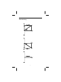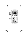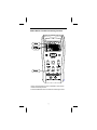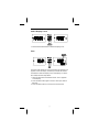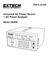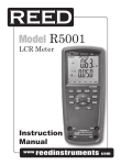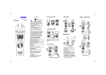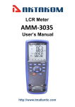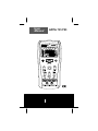
1
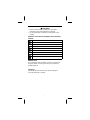
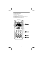
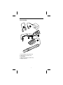
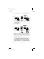
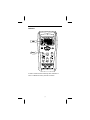
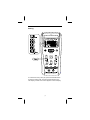
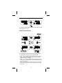
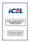
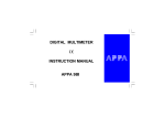
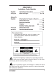
User
Manual
APPA 701/703
Warning
Warning
Safety
Safetysheet
sheet
..........
..........
..........
........
.........
..........
..........
........
.........
Read First
Safety Information
Understand and follow operating instructions carefully.
Use the meter only as specified in this manual; otherwise,
the protection provided by the meter may be impaired.
WARNING
Identifies hazardous conditions and actions that could cause
BODILY HARM or DEATH
CAUTION
Identifies conditions and actions that could DAMAGE the meter
or equipment under test
WARNING
˙ When using test leads or probes, keep your fingers behind
the finger guards.
˙ Remove test lead from Meter before opening the battery
door or Meter case.
˙ Use the Meter only as specified in this manual or the protection by the Meter might be impaired.
˙Always use proper terminals, switch position, and range for
measurements.
˙ Do not apply more than the rated voltage, as marked on
Meter, between terminals or between any terminal and
earth ground.
˙ Use caution with voltages above 30 Vac rms, 42 Vac peak,
or 60 Vdc. These voltages pose a shock hazard.
˙ To avoid false readings that can lead to electric shock and
injury, replace battery as soon as low battery indicator.
˙ Discharge all high-voltage capacitors before testing.
˙ Do not use Meter around explosive gas or vapor.
˙To reduce the risk of fire or electric shock do not expose this
product to rain or moisture.
1
CAUTION
˙ Never connect a source of voltage that could result in
damage the meter and the equipment under test.
˙ Do not expose Meter to extremes in temperature or high
humidity.
Symbols as marked on the Meter and Instruction
manual
Risk of electric shock
See instruction manual
DC measurement
<
Battery
Fuse
Earth
AC measurement
Conforms to EU directives
Do not discard this product or throw away.
Maintenance
Do not attempt to repair this Meter. It contains no userserviceable parts. Repair or servicing should only be performed by
qualified personnel.
Cleaning
Periodically wipe the case with a dry cloth and detergent.
Do not use abrasives or solvents.
2
The Meter Description
Front Panel Illustration
1. LCD display : 20000/2000 counts .
2. Function buttons.
3. 5-Wire input terminal for SMD test probe or DIP part.
4. 2-Wire input terminal for Alligator Clip.
3
The assembly
1. 5V AC Adapter (only APPA 703)
2. USB Cable (only APPA 703)
3. Shorting Bar
4. SMD Test Probe (only APPA 703)
5. Alligator Clip Set.
4
Measuring Principle
E = R + j(X
Z =
− XC )
L
R 2 + (X
L
− X C ) ≤ tan
X L = 2 π fL = ω L
XC =
1
1
=
2 π fC
ωC
⎛ XL − XC
R
⎝
θ = tan − 1 ⎜⎜
Q =
⎞
⎟⎟
⎠
1
= tan θ
D
Series Measuring
Z = R S + jX
S
Parallel Measuring
Y =
1
1
+
RP
jX
P
5
−1
⎛ XL − XC
⎜⎜
R
⎝
⎞
⎟⎟
⎠
Phase Drawing
6
Making 5-wire measuring with the SMD test
probe
7
Making 4-wire measuring in the 5-wire terminal
Making 2-wire measuring with the alligator clip
set
8
Measuring L/C/R/DCR
• Press the L/C/R/DCR button to select the measuring function.
• Press the L/C/R/DCR button for 2 seconds to enter the Auto
L/C/R function.
9
Measuring D/Q/ESR/θ
• Press the D/Q/ESR/θ button to select the measuring function.
• The θ function is only at APPA 703.
10
Select test Frequency
• Press the FREQ button to select the test frequency.
• The 100KHz test frequency is only at APPA 703.
11
Select Series / Parallel measuring function
• At the L/C/R measuring function, it defaults to Auto Series /
Parallel measuring function.
• Press the SER/PAL button to select the measuring function.
12
Select Display Count
• Press the 2000 /20000 button to select the display count.
Zero
The Zero mode records the current input value as reference and
appears on the sub display. The after input values will subtract
the reference value and display on the main display. To use the
Zero mode, follow the steps below.
1. Press the Zero button to enter Zero mode. The “Δ” appears
on the display.
2. Press the Zero button again to record a new input value as
reference.
3. Press the Zero button for 2 seconds to exit this mode.
13
Display Hold
• Press the HOLD button to hold the reading of the meter, press
the button again to return.
Display MAX/MIN
The MAX/MIN mode records the maximum and the minimum
input values. When the inputs go below the recorded minimum
value or above the recorded maximum value, the meter beeps
and records the new value.
To use the MAX/MIN mode, follow the steps below.
1. Press the MAX/MIN button to enter the MAX/MIN mode.
The “MAX” appears on the display, the maximum value on
the main display and the current value on the sub display.
2. Press the MAX/MIN button to select the MAX or MIN display.
3. Press the MAX/MIN button for 2 seconds to exit this mode.
Note : This function is only at APPA 703.
14
Calibrate
In order to achieve the best measuring result, calibration is
must. To calibrate the meter, press the CAL button.
15
When “OPEn” appears on the sub display, make the terminal or
the SMD test probe open, and press the CAL button to start
open calibration. About 30 seconds later, the result of the open
calibration appears on the main display. If the result is pass,
press the CAL button to next step. If the result is fail, press the
CAL button to exit the function.
16
When “Srt” appears on the sub display, make the terminal or the
SMD test probe short, and press the CAL button to start short
calibration. About 30 seconds later, the result of the short
calibration appears on the main display. If the result is pass,
press the CAL button to complete the calibration. If the result is
fail, press the CAL button to exit the function.
17
Sorting
To check the accuracy of the part, press the SORTING button
to enter the sorting mode. The sorting result appears on the
main display, and the current value appears on the sub display.
18
The default sorting standard value is the current value, and the
default tolerance is ±1.0%.
Setup Sorting Standard
To setup the sorting standard value, follow the steps below.
1. Press the SETUP button to enter the setup mode.
2 Press Y and Z button to setup the range of the standard
value. Then press the ENTER button to save the setup
value and enter the next step.
3. Press △ ,V, Y and Z button to setup the standard value.
Then press the ENTER button to save the setup value and
enter the next step.
4. Press Y and Z button to setup the tolerance value. Then
press the ENTER button to save the setup value and exit
this mode.
19
Battery Replacement
Refer to the following figure to replace the batteries :
Caution
˙ Replace the batteries as soon as the low batteries indicator
appears, to avoid false reading.
˙1.5V x 4 alkaline batteries.
External Power Source
To save the batteries power by using the external power source.
Caution
˙Use the 5V AC adapter only as specified in this manual.
˙Do not apply the other source connect to the meter.
20
Specifications
General Specifications
Maximum voltage applied to any terminal :
30VDC or 30VAC rms
Display : 2000/20000 counts
Overrange Indication : OL
Batteries Life : 50 hours
" is displayed when the batteries
Low Batteries Indication :"
voltage drops beow operating voltage.
Low battery voltage : Approx. 4.5V
Auto Power Off : 10 minutes.
Operating Ambient : Non-condensing ≦10°C,
11°C ~ 30°C (≦80% RH),
30°C ~ 40°C (≦75% RH),
40°C ~ 50°C (≦45%RH)
Storage Temperature :
-20°C to 60°C , 0 to 80% R.H. (batteries not fitted)
Temperature Coefficient :
0.15 x (Spec.Accy) / °C, < 18°C or > 28°C .
Measure : Samples 1.25 times per second normal.
Altitude : 6561.7 ft (2000m)
Weight : (630g) including battery.
Dimensions (W x H x D) :
95mm x 207mm x 52mm with holster.
Accessories :
Battery (installed), Test leads and User manual.
(The probe assembly provided with the product are for use with
meter)
Power Requirements : 1.5V x 4 IEC LR6 or AA size.
Pollution Degree : 2
Safety : Complies with EN 61010-1, IEC 61010-1
EMC : EN 61326-1
Shock Vibration : Sinusoidal vibration per MIL-T- 28800E
(5 ~ 55 Hz, 3g maximum).
Drop Protection : 4 feet drop to hardwood on concrete floor.
Indoor Use.
21
Electrical Specifications
(1) Test Frequency :
Range
Resolution
Accuracy
100.00 Hz
0.01 Hz
± 0.01%
120.00 Hz
0.01 Hz
± 0.01%
1.0000 kHz
0.1 Hz
± 0.01%
10.000 kHz
1 Hz
± 0.01%
100.00 kHz
10 Hz
± 0.01%
(2) Test Signal :
AC Signal Level : 600mVrms
AC Signal Accuracy : ±10%
DC Bias Level : 1V
DC Bias Accuracy : ±10%
(3) Test Cable :
Model
Length
Bandwidth
Type
SMD Test Probe
60cm
1MHz
5-Wire
4-Wire Test Probe
60cm
1MHz
5-Wire
Alligator Clip Set
15cm
1kHz
2-Wire
Accuracy : ± (A x B) (% of reading)
A : Basic Accuracy as specified by
B : Test Cable Accuracy
B(%) = 1 + (L x F x T)
L(m) : Cable Length
F(MHz) : Test Frequency
T : Cable Type. If the cable is 5-Wire type, the "T" is 40, and the
other is 4,000.
When measuring by basic accuracy that following
conditions must be met :
1. Ambient temperature : 23°C ± 5°C < 80%RH.
2. Test cable length : 0 m
3. Open and short corrections have been performed.
4. D ≤ 0.1 for C, L measurements; Q ≤ 0.1 for R measurements.
See the operation manual for additional conditions.
22
(4) Inductance
Frequency
100Hz
120Hz
Range
20.000mH
200.00mH
2000.0mH
20.000H
Accuracy
± (0.5% + 5d) [2]
± (0.2% + 5d)
200.00H
2000.0H
± (0.5% + 5d)
20.000KH
± (1.0% + 5d) [2]
2000.0uH
± (0.5% + 5d) [2]
20.000mH
200.00mH
1KHz
2000.0mH
± (0.2% + 5d)
20.000H
200.00H
± (0.5% + 5d)
2000.0H
± (1.0% + 5d) [2]
200.00uH
± (0.5% + 5d) [2]
2000.0uH
10KHz
100KHz [1]
20.000mH
± (0.2% + 5d)
200.00mH
2000.0mH
20.000H
20.000uH
200.00uH
2000.0uH
20.000mH
± (2.0% + 5d)
± (5.0% + 5d)
± (0.5% + 5d) [2]
200.00mH
± (5.0% + 5d)
± (0.2% + 5d)
± (2.0% + 5d)
[1] The 100KHz test frequency is only at APPA 703.
[2] The measuring time is 2 seconds.
Input Protection : 30VDC or 30VAC rms
Minimum Resolution : 0.001uH in the 20.000uH range.
Measuring Time : 800ms
2-wire Accuracy : Add 1.0% to accuracy.
Note : If D > 0.1, the accuracy should be multiplied by 1 + D 2
23
(5) Capacitance
Frequency
Range
Accuracy
2000.0pF
± (0.5% + 5d) [2]
20.000nF
200.00nF
100Hz
120Hz
2000.0nF
± (0.2% + 5d)
20.000uF
200.00uF
± (0.5% + 5d)
2000.0uF
± (1.0% + 5d)
20.000mF
± (2.0% + 5d) [2]
2000.0pF
± (0.5% + 5d) [2]
20.000nF
200.00nF
1KHz
10KHz
100KHz [1]
± (0.2% + 5d)
2000.0nF
20.000uF
200.00uF
± (0.5% + 5d)
± (1.0% + 5d)
2000.0uF
200.00pF
2000.0pF
20.000nF
200.00nF
2000.0nF
20.000uF
200.00uF
± (2.0% + 5d) [2]
± (0.5% + 5d) [2]
± (0.2% + 5d)
± (0.5% + 5d)
± (2.0% + 5d)
± (5.0% + 5d) [2]
20.000pF
200.00pF
± (0.5% + 20d) [2]
2000.0pF
± (0.2% + 5d)
20.000nF
200.00nF
2000.0nF
20.000uF
± (2.0% + 5d)
± (5.0% + 5d) [2]
± (0.5% + 5d)
[1] The 100KHz test frequency is only at APPA 703.
[2] The measuring time is 2 seconds.
Input Protection : 30VDC or 30VAC rms
Minimum Resolution : 0.001pF in the 20.000pF range.
Measuring Time : 800ms
2-wire Accuracy : Add 1.0% to accuracy.
Note : If D > 0.1, the accuracy should be multiplied by 1 + D 2
24
(6) Resistance
Frequency
Range
Accuracy
200.00Ω
2.0000KΩ
100Hz
120Hz
20.000KΩ
± (0.2% + 5d)
200.00KΩ
2.0000MΩ
20.000MΩ
± (0.5% + 5d)
200.00MΩ
± (1.0% + 5d) [2]
20.000Ω
200.00Ω
± (0.5% + 15d) [2]
2.0000KΩ
1KHz
20.000KΩ
200.00KΩ
± (0.2% + 5d)
2.0000MΩ
20.000MΩ
± (2.0% + 5d)
200.00MΩ
± (5.0% + 5d) [2]
20.000Ω
± (0.5% + 15d) [2]
200.00Ω
2.0000KΩ
10KHz
100KHz [1]
20.000KΩ
200.00KΩ
2.0000MΩ
20.000MΩ
20.000Ω
200.00Ω
2.0000KΩ
± (0.2% + 5d)
± (2.0% + 5d)
± (5.0% + 5d)
± (0.5% + 15d) [2]
± (0.2% + 5d)
20.000KΩ
200.00KΩ
± (2.0% + 5d)
2.0000MΩ
± (5.0% + 5d)
[1] The 100KHz test frequency is only at APPA 703.
[2] The measuring time is 2 seconds.
Input Protection : 30VDC or 30VAC rms
Minimum Resolution : 0.001Ω in the 20.000Ω range.
Measuring Time : 800ms
2-wire Accuracy : Add 1.0% to accuracy.
Note : If Q > 0.1, the accuracy should be multiplied by 1 + Q 2
25
(7) DCR
Range
Resolution
200.00Ω
0.01Ω
Accuracy
2.0000KΩ
0.0001KΩ
20.000KΩ
0.001KΩ
200.00KΩ
0.01KΩ
2.0000MΩ
0.0001MΩ
20.000MΩ
0.001MΩ
± (0.5% + 5d)
200.00MΩ
0.01MΩ
± (1.0% + 5d) [1]
± (0.2% + 5d)
[1] < 50dgt rolling.
Input Protection : 30VDC or 30VAC rms
Minimum Resolution : 0.01Ω in the 200.00Ω range.
Measuring Time : 2 seconds
2-wire Accuracy : Add 1.0% to accuracy.
(8) D & Q
Definition Q=1/D
Range : 2.000 ~ 2000
Minimum Resolution : 0.001 in the 2.000 range.
Accuracy : Accuracy of Main Reading x (1+D)
Input Protection : 30VDC or 30VAC rms
2-wire Accuracy : Add 1.0% to accuracy.
(9) ESR :
The specification of ESR is same as Resistance.
(10) θ:
Range
Resolution
Accuracy
-90.0° ~ 90.0°
0.1°
± (0.2% + 5d)
Input Protection : 30VDC or 30VAC rms
2-wire Accuracy : Add 1.0% to accuracy.
Note : The θ function is only at APPA 703.
26
Limited Warranty
This meter is warranted to the original purchaser against defects
in material and workmanship for 2 years from the date of
purchase. During this warranty period, Manufacturer will, at its
option, replace or repair the defective unit, subject to verification
of the defect or malfunction.
This warranty does not cover Carlos fuses, disposable batteries,
or damage from abuse, neglect, accident, unauthorized repair,
alteration, contamination, or abnormal conditions of operation or
handling.
Any implied warranties arising out of the sale of this product,
including but not limited to implied warranties of merchantability
and fitness for a particular purpose, are limited to the above.
The manufacturer shall not be liable for loss of use of the
instrument or other incidental or consequential damages,
expenses, or economic loss, or for any claim or claims for such
damage, expense or economic loss. Some states or countries
laws vary, so the above limitations or exclusions may not apply
to you.
27
APPA TECHNOLOGY CORP.
9F.119-1 Pao-Zong Rd., Shin-Tien,
Taipai, 23145, Taiwan, R.O.C.
Tel : 886-2-29178820
Fax : 886-2-29170848
E-MAIL : info @appatech.com
http ://www.appatech.com