1
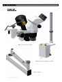
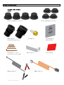
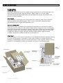
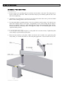
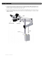
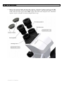
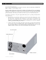
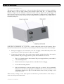
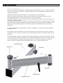
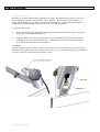
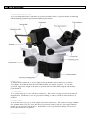
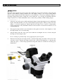
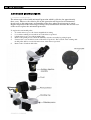
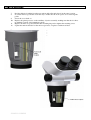
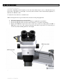
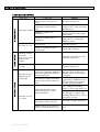
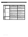
SO-111W Microscope
INTRODUCTION .................................................................................................5
PARTS LIST..........................................................................................................6
PACKAGING ........................................................................................................9
ASSEMBLY INSTRUCTIONS ......................................................................... 10
Fixing to a table
Assembling the arm and head
Connecting to a power source
Changing the light intensity
Battery operation, maintenance and safety
Arm assembly adjustments
Gas spring adjustment
Microscope head assembly
Tilt function
Zoom function
Focus function
10
10
13
14
14
15
16
17
17
17
17
USING THE MICROSCOPE ............................................................................. 18
Sterilisation
Moving the head into position
Focussing the microscope
18
18
18
ROUTINE CARE AND MAINTENANCE ....................................................... 19
OPTICAL HEAD
Cleaning the optical components
Cleaning the plastic parts and paintwork
Do not dismantle
Protection against mould
LIGHTING SYSTEM
Lamp life
Replacing the lamp
19
19
19
19
19
20
20
20
ADVANCED INSTRUCTIONS ........................................................................ 21
Replacing mould protection
Adjusting focus friction
21
23
TROUBLESHOOTING...................................................................................... 24
SPECIFICATIONS............................................................................................. 26
Please read the following information carefully before installing and using the
Scan Optics ophthalmic microscope. Scan Optics is responsible for the safety,
reliability and performance of the equipment only if it is used in accordance
with these instructions.
This microscope is designed for use by a certified practitioner, for magnified
observation of patients, and for use in an operating theatre as an observation aid
during surgery. Environmental storage and packing conditions of 60-95%
relative humidity and 10-40 °C, are recommended for this product.
No parts or accessories supplied with this microscope are supplied in a sterile
condition.
Apart from those identified in the instructions within this manual, there are no
user-serviceable parts in this microscope. Scan Optics will retain the discretion
to advise whether any repairs may be carried out by external qualified technical
personnel, or whether part(s) of the microscope must be returned to the
manufacturer s premises for service or repairs to be carried out under warranty
or otherwise. Where appropriately qualified technical personnel are identified
by a user, and ratified by Scan Optics, then Scan Optics will make available on
request any information which may assist in maintaining or repairing this
equipment.
Scan Optics Pty Ltd
32 Stirling Street
Thebarton
SA 5031
AUSTRALIA
www.scanoptics.com.au
[email protected]
Micros cope he a d as s e mbly
Cla mp a nd powe r s upply a s s e mbly
Arm a s s e mbly
Focus ste rilis a ble cove rs (4)
Zoom s terilis a ble cove rs (4)
P la in e ye pie ce (1)
Focus able e ye pie ce (1)
S pa re la mp (1)
Us e r ma nua l (1)
(this ma nua l)
S ocke t keys (s et 7;
(1.5, 2, 2.5, 3, 4, 5, 6 mm)
Dus t cover (1)
Le ns cloth (1)
Ba tte ry ca ble (1)
Ma ins ca ble (1)
SO-331
SO-1440
SO-1350
(large and small monitor versions available)
Table plate
Spare pair focus sterilisable covers
Spare pair zoom sterilisable covers
Spare handle sterilisable cover
Side handle
Gel cell battery (7Ah capacity)
Gel cell battery charger for SO-217
Gel cell battery (38Ah capacity)
Gel cell battery charger for SO-9210
SO-291
SO-545
SO-546
SO-547 (fits side handle)
SO-572
SO-217
SO-261 (220/240V) or SO-262 (110/120V)
SO-9210
SO-9220
Scan Optics aluminium transit cases provide the best protection for a microscope where it is
likely to transported to more than one location. These transit cases are fitted with
polyurethane-polyetherfoam which houses the individual microscope subassemblies and
provides excellent durability.
As an alternative, microscopes can also be packed in a reinforced nylon suitcase which is
indistinguishable from normal luggage. These cases are also fitted with polyurethanepolyetherfoam, and are lighter than aluminium cases.
Where microscopes are unlikely to be transported to more than one location, the standard
packaging provides solid protection within a double-walled corrugated carton. Polyethylene
foam inserts are provided to protect the contents of the carton. Please do not dispose of these
packaging materials, but retain all the packaging within the carton for future use. The head
assembly box contains an upper and lower moulded cushion which support the head
assembly. Retain these cushions within the box for future use.
If the microscope is to be stored or transported, it is recommended that the original packaging
be re-used for this purpose. If possible, re-pack each assembly in its original plastic bag,
including a dehumidifying silica gel desiccant in the bag to reduce moisture. The best storage
location is a low humidity, dust-free environment, such as an air-conditioned room.
1. Fix the clamp to the operating table about 40 cm from the head of the table. The clamp may be
fixed on either side of the table. Make sure that the clamp is pressed firmly against the side of the
table before tightening.
2. Alternatively, the clamp may be mounted on any horizontal surface that can be positioned within
60 cm of the working position, such as a mobile trolley.
3. It is important that the mounting surface be free from vibration and movement. Note that in cases
where the mounting surface is not rigid, over-tightening of the vertical clamp will not improve
microscope stability. In this case, add a stiffening plate (such as Scan Optics Table Plate; Cat No.
SO-291) beneath the mounting surface and apply the clamp over the stiffening plate and the
original mounting surface.
1. Locate the pillar safety clamp and place it on the pillar if it is not there already. Tighten the pillar
safety clamp at a point midway up the pillar.
2. Place the arm assembly on the pillar. Make sure that the arm assembly rests against the pillar
safety clamp. Loosen the elbow knob to allow the pantograph arm to rotate about the elbow joint.
3. Locate the microscope head assembly in the end of the arm assembly. Make sure the microscope
assembly is seated all the way down in the collet. Tighten the wrist knob underneath the end of
the arm assembly to secure the microscope in the collet.
4. Pass the cable through the clips on the arm assembly and attach the plug to the socket on the top
of the power supply. This will ensure the cable does not obstruct the surgeon or come into contact
with the sterile area.
5. Remove the eyepiece blanks and insert the eyepieces. Insert the focusing eyepiece in the LHS
eyepiece tube from the observer s perspective and secure in place so that the scale marker is easily
visible. Place the fixed eyepiece in the RHS eyepiece tube and secure using the screw. Retain the
eyepiece caps in a safe place for when storing the microscope.
The Scan Optics Ophthalmic Microscope may be connected to either an earthed mains (100-240V 5060Hz) ac supply, or a 12V dc supply, or both.
If both ac and dc supplies are connected, the dc supply (eg 12V battery) will act as an emergency
backup for mains power. In this case, the microscope will not run from battery power unless the mains
supply fails or is switched off. If mains power is restored, the microscope will resume using mains
power automatically. The mains power switch on the microscope does not switch the battery off.
Connecting a 12V batter y to the power supply while mains power is oper ating nor mally will not
char ge the batter y.
1. Plug the mains power cable into a mains power socket. Use the cable retaining clip to secure
the cable in place. International safety standards do not allow the use of an extension cord.
The mains power supply must have a pr otective ear th conductor . If there in no earth
conductor, or if the integrity of the earth conductor arrangement is in doubt, the equipment
must be operated from a 12Vdc power source.
2.
Switch on the mains power supply at the mains socket. The power supply will automatically
detect the input voltage between 100 and 240V. When the ON/OFF switch is selected to ON,
the power supply indicator on the switch will light up and the lamp will come on if the
lamphouse cable is connected to the socket on the top panel of the power supply.
When the power supply is switched on, soft start circuitry will turn the lamp on slowly to minimise
thermal shock to the cold lamp, which would otherwise reduce lamp life. To change the light
intensity, simply rotate the intensity control knob found on the top panel of the power supply. If
battery power is used or cuts in due to a mains power interruption, a slight decrease in light intensity
may be noticed. This is normal, and the amount of light reduction will depend on the charge status of
the battery being used.
Scan Optics recommend the use of gel cell or sealed rechargeable lead-acid 12V batteries. These
batteries are maintenance-free and can be operated, charged or stored in any position without leakage.
1. If the power supply is to be connected to a 12-volt dc supply, connect the battery cable to the
3-pin connector on the bottom panel on the power supply.
2. Connect the red battery clip to the positive battery terminal, and the black clip to the negative
battery terminal. The power supply will not operate if the terminals are reversed
The 12 volt supply must be direct current. The power supply will not operate with 12
volts alternating current.
Ensure batteries have adequate airflow around them before charging.
Avoid short-circuiting batteries.
Old lead-acid batteries of any type must be disposed of correctly. It is recommended
that they are recycled by an appropriate establishment who recycle car batteries. Lead
acid batteries should not be disposed of with ordinary waste, as lead poisoning or acid
trauma may result.
Wher e batter y backup is used, Scan Optics r ecommends a per iodical check of the batter y to
ensur e it is char ged and functional.
The arm assembly includes a number of features which enable the microscope to be adjusted in almost
any position. The best combination of settings will depend on the individual user and the particular
surgical environment.
The pillar knob allows the arm assembly to be locked in position about the pillar.
The elbow knob allows the shape of the arm to be locked in position; that is the position of the
pantograph section relative to the horizontal section of the arm assembly.
The friction handle allows the vertical movement of the pantograph section of the arm assembly to be
restricted or locked in position.
The wrist knob allows the head assembly to be locked in position relative to the pantograph section of
the arm assembly. This knob should not be unlocked after the head assembly has been adjusted. This
will prevent accidental dislodgement of the head assembly when attempting vertical positioning
manoeuvres.
In a typical configuration; the pillar knob would be left slightly loose but the elbow and wrist knobs
would be locked.
Note that the safety clamp must be in position dir ectly under the hor izontal section of the ar m
assembly for safe oper ation of the micr oscope; this will pr event the ar m assembly sliding down
the pillar .
The friction handle could be set such that when vertical adjustments of the pantograph arm are made,
the arm will stay in position after being moved. This will allow the microscope to be swung out of the
way about the pillar after surgery while the patient is moved. When the next patient is ready, the
microscope can be swung in again and it will already be in a good approximate position.
The microscope arm is fitted with an adjustable gas spring. By adjusting the position of one end of
the gas spring, the amount of upward force can be changed. Thus if accessories are added to or
removed from the microscope, the force setting can be adjusted to compensate for the change in
weight, thereby maintaining the same desired feel of the arm movement.
To adjust the gas spring:
1.
With one hand, push the pantograph arm down until it is in the horizontal position. This will
expose the socket in the adjusting screw.
2.
Using the 5mm socket key provided in the tool box, rotate the screw clockwise to move the
adjusting nut up and decrease the arm force. Alternatively rotate the screw anti-clockwise to
move the nut down and increase the arm force.
CAUTION:
Always check the ar m movement over the entir e up/down str oke of the ar m. If the micr oscope
is heavily loaded with accessor ies and the ar m for ce is set too low, the ar m may dr op suddenly if
it is not adequately r estr ained with the fr iction lock.
A good working knowledge of the microscope head assembly will be of great assistance in achieving
and maintaining optimum optical and mechanical performance.
To tilt the head assembly up or down, simply rotate the tilt knob anti-clockwise or clockwise
accordingly. Note that the entire head assembly will tilt, not just the eyepieces. To ease this
operation, support the weight of the microscope head with one hand while using the other hand to
rotate the knob.
To zoom the image in or out, rotate the zoom knob(s). The total zoom range is between 4x and 25x
magnification. Sterilisable covers are provided for fitting over the zoom knobs when sterile use is
required.
To focus the microscope up or down, simply rotate the focus knob(s). The total focus range is 50mm.
For optimum microscope use, leave the microscope head in such a position to allow approximately
25mm of focus range in each direction. Sterilisable covers are provided for fitting over the focus
knobs when sterile use is required.
!
Scan Optics microscopes are supplied with two sets of sterilisable covers – one set may be used while
the other set is undergoing sterilisation. Additional sterilisable covers may be purchased from Scan
Optics in the event of loss or damage. Simply slip the covers on to the zoom or focus knobs when
required.
The covers may be sterilised by:
boiling
autoclaving
chemical sterilisation
gas sterilisation.
Note that national authorities may require the use of specific sterilisation or disinfection methods.
"
Note that sterilised covers should be applied to the manual focus and zoom knobs and the guide
handle (if used) before these parts of the microscope are touched by a sterile operator.
1.
Move the head into approximate position using the arm assembly articulations.
2.
Move the microscope focus up to the half-way position. This should leave approximately
25mm of movement up or down from the central position.
3.
Use the pantograph arm articulation to move the head up or down while looking through the
eyepieces to roughly focus the microscope.
4.
If the microscope eyepieces are higher than the most comfortable position for the operator and it
is not possible or practical to adjust the operator s seat, rotate the tilt knob clockwise to tilt the
head of the microscope down. The range of tilt adjustment is from 45° downward to 5° above
the horizontal.
Focussing the microscope in the correct sequence is an important step in setting up for use.
1.
Set the pupillary distance of the microscope by moving the eyepieces apart or together as
required. The eyepieces are geared together and will move equal distances on either side of the
optical centre of the microscope.
2.
Set the refractive error scale to zero on the LHS eyepiece.
3.
Choose a high magnification zoom setting or one which is typically used in surgery.
4.
Close the left eye and look through the right eyepiece of the microscope with the right eye only.
5.
Focus the microscope slowly until the image is sharply in focus.
6.
Close the right eye and look through the left eyepiece of the microscope with the left eye only.
7.
Rotate the refractive error adjustment ring on the left eyepiece until the left eye is in focus. The
reading on the ring will give an approximate measure of the relative refractive error between the
left and right eyes.
8.
Look through both eyepieces normally and check that the image is focussed and that stereopsis
is achieved.
The eyepieces, objective lens and lamphouse prism should be checked for cleanliness each time the
instrument is used. Surface dust should be removed with a clean, soft brush. Fingerprints, irrigation
solution residue and grease may be removed by lightly wiping with a cotton cloth or lens tissue
moistened with a mixture of 70% ether and 30% absolute alcohol (either ethanol or methanol). Use
pure alcohol if no ether is available.
Do not use acetone as it may damage the sur face coatings of the lenses.
#
Use water based cleaners only.
Do not use any or ganic solvent such as alcohol, ether or xylene.
$
Apart from instructions specifically mentioned within this manual, no parts inside the optical head of
the instrument can be serviced by the user. Attempts to dismantle the optical head or prism cover will
make any warranty void.
%
In hot and humid climates it is common for mould to grow on optical surfaces. Cleaning and repairing
the damage can be expensive and inconvenient. To minimise the risk of mould forming, do not leave
the instrument without either eyepieces or eyepiece blanks inserted and always store the optical head
in a sealed bag containing silica gel desiccant. Scan Optics SO-111W microscopes are fitted with antimould protection. In tropical climates, routine checking for the presence of mould is recommended.
&
The main lamp supplied has a rated average life of 50 hours; however the actual life of the lamp will
depend on the intensity setting normally used. The highest setting is an over-run setting which
increases light output but will reduce lamp life to about 20 hours. Conversely, running the lamp at a
mid-range setting will produce a lamp life of about 80 hours. It is strongly recommended that the
lamp be replaced as a routine maintenance task, to reduce the possibility of failure during surgery.
'
1.
Always use protective gloves while replacing the lamp as lamp temperatures may be sufficiently
high to burn skin should it come into contact with the quartz capsule. Where possible, allow the
lamp to cool before replacing it. Ensure that the new lamp is free of grease or finger prints
before replacement. Any such marks should be removed with a solvent such as ethanol to avoid
reducing lamp life.
2.
First grip the lamp module located beneath the cable gland on the side of the lamphouse. Pull
the lamp module out to reveal the lamp.
3.
Grip the lamp at the side of the gold section where the rectangular cut-out is located, and pull
the lamp out of the lamp module.
Do not attempt to pull the lamp out by gr ipping the quar tz capsule.
4.
Push the new lamp into the lamp module so that the lamp flange sits flush on the front of the
gold tube section. Replace the lamp module in the socket in the lamphouse, so that the pins
click into place. Correct lamp replacement using this method is essential for ensuring good
illumination.
'
The microscope is fitted with anti-mould protection which is effective for approximately
three years. However, the effective life of this protection will depend on environmental
factors such as the temperature and humidity of the place where the microscope is stored.
Regular inspection of the microscope will help early identification of mould and alert the user
of the need to replace the anti-mould protection.
To replace the anti-mould pellet:
1.
Zoom the microscope to the lowest magnification setting
2.
Loosen the retaining screw at the front of the microscope head.
3.
Lift the microscope out of the mounting ring
4.
Remove the prism protector from the auxiliary objective assembly by prying it apart
5.
Unscrew the cover from the bottom of the microscope head. The location of the existing antimould pellet will be revealed from the front of the microscope head.
6.
Remove the old anti-mould pellet.
7.
8.
9.
10.
11.
12.
Peel the adhesive backing from the new anti-mould pellet and place it in the same location.
Zoom the microscope in and out all the way to make sure the zoom optics do not disclodge the
pellet.
Screw the cover back on.
Replace the prism protector on the auxiliary objective assembly, making sure that the slot lines
up with the location of the lamphouse prism.
Replace the microscope head back in the mounting ring and re-tighten the retaining screw.
Update the anti-mould label on the microscope head, or replace it with a new label.
Over time, depending on the frequency of use, the focus friction may loosen, so that the microscope
head starts to fall under its own weight. Conversely the focus knobs can be inadvertently tightened, so
that they are difficult to turn.
To adjust the focus friction to a suitable level:
While viewing the microscope from the front, mounted on the pantograph arm;
1.
2.
3.
4.
Hold the left hand side focus knob firmly
Rotate the right hand side focus knob clockwise to tighten the focus friction
Rotate the right hand side focus knob anti-clockwise to loosen the focus friction
Release the LHS knob and test the feel of the focus system by rotating either the LHS or
RHS knob on its own. The system should allow the microscope head to be focussed up or
down easily without falling under its own weight.
The image is blurry
If the microscope or object has
moved it may no longer be in
focus.
A different user may require
adjustment for their refractive
error.
Check the eyepieces for
cleanliness.
Check the objective lens for
cleanliness.
No image is seen
The microscope is
falling under its
own weight
Adjust the eyepieces for
refractive error – refer Focussing
the microscope.
Carefully remove and clean the
eyepieces if they are dirty, then
replace them.
Carefully clean the objective lens,
taking care not to damage the
lamphouse prism.
Check that the eyepieces have
been inserted.
Insert the eyepieces.
Check for obstructions in the
viewing path
Remove the obstruction.
The focus system
allows the
microscope to fall
under its own
weight
The focus system is
too stiff
Refocus the microscope.
Adjust the focus friction – refer
Advanced instructions
Check for obstructions
Adjust the focus friction – refer
Advanced instructions
Loosen the arm friction handle
and observe if the pantograph arm
offers any significant resistance to
downward pressure
If it does not then the gas spring
may have failed. Contact your
distributor, local service agent or
Scan Optics.
Adjust the gas spring to
compensate for additional load on
the end of the microscope arm refer Gas spring adjustment
Locate the gas spring adjustment
near the elbow joint between the
arms.
Check that the microscope is
securely clamped to a stable
horizontal surface
The microscope is
not stable
Check that the appropriate friction
knobs have been set correctly
Check if the microscope head is
seated correctly in the wrist joint.
If not, change the mounting
surface to a more appropriate one.
Use the optional Scan Optics SO291 table plate to stiffen a thin
mounting surface such as a sheetmetal table or trolley.
Refer Arm assembly adjustments
Refer Assembling the arm and
head
The light is too dim
There is no light
There is no power
Remove the lamp module and
check for blackening or failure.
Check the intensity setting on the
front panel. The intensity may be
set low.
Check if there is mains power
available (green LED on the main
switch)
Check the intensity setting on the
front panel. The intensity may be
set to zero.
Check if the lamp module is
correctly inserted in the side of
the lamphouse.
Check if the cable is connected to
the socket on the top panel of the
power supply
Replace a blackened or failed
lamp.
Check the power supply
See below
Check the mains power supply
Use battery power if no mains
power is available.
Turn the mains power off and
check the circuit breaker on the
bottom panel
Push the circuit breaker back in
after waiting a few minutes.
Increase the lamp intensity using
the adjusting knob.
Switch to battery power if no
mains power is available.
Increase the lamp intensity using
the adjusting knob.
Ensure the module clicks
positively into place.
If not, connect it.
VIEWING SYSTEM
MAGNIFICATION
WORKING DISTANCE
FIELD OF VIEW
REFRACTIVE ERROR
FOCUSING
INTERPUPILLARY DISTANCE
ALIGNMENT
LAMP
FILTERS
LAMP LIFE
ILLUMINATION
MAINS POWER
OUTPUT
INTENSITY CONTROL
EARTHING
Binocular, stereoscopic
(convergence angle 10o)
Eyepiece tube inclination 45o
Zoom magnification, range 4.2 x - 25x
Auxiliary objective to object distance 160 mm
15 - 65mm, depending on magnification
+/- 5D left eyepiece
Range ± 25mm
Adjustable for Distance PD range approximately
50 to 80mm
Coaxial with viewing system, high intensity
12V 50W quartz-halogen lamp
Internal ultraviolet and infrared filters
20 hours at highest intensity
80 hours at medium intensity
75,000 Lux minimum at maximum setting
(with a new lamp)
100-240V, 50-60Hz switch-mode auto selecting
Regulated output with soft start
Continuous
Via earth lead of mains power cable
(green/yellow)
DIRECT CURRENT
12 V dc source optional
CIRCUIT BREAKER
3A resettable type
CABLE: Mains
CABLE: Battery
Length 5 metres
Length 5 metres
CLAMP
HEAD TILT
VERTICAL TENSION
Throat 70 mm
+5 to -45
Adjustable gas spring to set lifting force
Vertical pillar to head optical axis maximum 930
mm (37")
Pantograph arm vertical range 320 mm (13")
No ferrous metals, preventing corrosion.
DIMENSIONS
MATERIALS
DIMENSIONS: Aluminium case
DIMENSIONS: Standard packaging
WEIGHT: In aluminium case
WEIGHT: In standard packaging
790 x 560 x 340 mm (31 x 22 x 13.5") (Including
packing carton)
810 x 520 x 290 mm (32” x 20.5” x 11.5”)
30 kg (66 lbs) (Including packing carton)
18 kg (40 lbs)