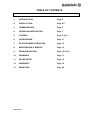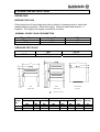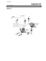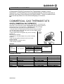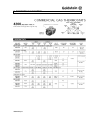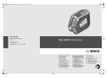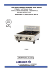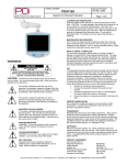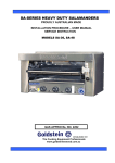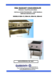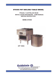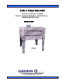
1
BAKE & PIZZA GAS OVEN
PROUDLY AUSTRALIAN MADE
INSTALLATION PROCEDURE – USER MANUAL
SERVICE INSTRUCTION
MODELS G236
ESTABLISHED 1911
The Cooking Equipment Professionals
www.goldsteineswood.com.au
TABLE OF CONTENTS
1.
INTRODUCTION
Page 3
2.
INSTALLATION
Page 4-5
3.
COMMISSIONING
Page 6
4.
OPERATING INSTRUCTION
Page 7
5.
CONTROL
Page 8, 9-10
6.
OVEN BURNER
Page 11
7.
PILOT& BURNER OPERATION
Page 12
8.
MAINTENANCE & SERVICE
Page 13
9.
PROBLEM SOLVING
Page 14-15-16
10.
DRAWINGS
Page 17
11.
SPARE PARTS
Page 18
12.
WARRANTY
Page 19
13.
BRANCHES
Page 20
IM030B2/p2
1. INTRODUCTION
Congratulations for purchasing your Goldstein commercial cooking appliance.
J. Goldstein & Co. is a wholly owned Australian company and have been
operating since 1911, building high quality products. The information in this
manual will assist your installer and ensure correct location and connection.
Thoroughly read the user instructions and the user maintenance sections, as
understanding your products, its operation, and its cleaning and service
requirements will provide you with long and satisfactory service. Failure to do
so could shorten the life of the product and decrease its efficiency. Please
ensure only authorised service technicians are called to any difficulties that
may arise.
INTRODUCTION
GOLDSTEIN BAKE & PIZZA GAS OVEN
MODEL G236
GOLDSTEIN BAKE & GAS OVENS are designed to give long and
satisfactory service and incorporate the best possible materials and
workmanship. Proper installation, adjustment and preventative maintenance
are vitally important if efficiency and appearance are to be maintained.
Read these instructions carefully as they contain important safety information
regarding the installation, use and maintenance of the appliance.
The G236 is designed especially for the purpose of baking and pizza making.
It has a heavy cordurite title floor and a wide shallow throat allowing an even
temperature and a quick recovery. This appliance can also be double stack.
RECEIVING INSPECTION
• Check crates for handling damage.
After carefully uncrating, check for
“concealed” damage. Report any damage immediately to carrier and to dealer.
• Remove check all loose items from unit and check contents as found on back of
warranty cards.
• Check type and capacity of gas supply.
• The type of gas for which this G263 is factory adjusted can be seen on the rating
plate, located on the bottom front panel of the Oven.
“THE EQUIPMENT MUST BE INSTALLED BY A
LICENSED GASFITTER
IM030B2/p3
2. INSTALLATION
PRE-INSTALLATION
Adequate ventilation must be provided, preferably by a hood with vent and exhaust
fan. Never make a direct connection between the flue of the Oven and the vent flue.
See that there is sufficient room between doors and openings to move equipment
into the kitchen. Check the data plate to ensure appliance is suitable for the gas
supply to which it will be connected and for information relative to gas input pressure
and consumption.
INSTALLATION
Please follow these instructions carefully
The Model G236 oven can be installed as a single unit and is then supplied with
790mm legs and an undershelf. .
1.
2.
3.
4.
5.
Remove all loose items from unit, check contents.
Remove unit from timber base.
Remove bricks, frame and burner reflector from oven.
Set unit in approximate position but on right hand side.
Bolt under shelf to the four (4) legs then bolt the legs to the underneath of the
G236 Oven.
Note: Care must be taken with this lift as it may be as much as 400 Kgs.
6.
Unit can be placed into correct position, observing the following minimum wall
clearance.
From rear wall
150mm
From right wall
25mm
From left wall
100mm
7.
Replace burner reflector, brick frame bricks.
Adjust height and level by means of adjustable feet, should be levelled left to
right but should have a slight fall to the front to allow normal fluing.
NOTE:
IM030B2/p4
The appliance must be installed by an authorised person and in accordance
with the regulations of the local Gas Authority, AS5601/AG601 and any other
authority having jurisdiction. The appliance has been tested and preset
before leaving our factory, but small adjustments may be necessary to suit
local conditions.
Correct operation of the appliance must be tested as part of the installation
procedure.
2. INSTALLATION
Have a licensed gas fitter or your local Gas Company connect the appliance.
Correct operation of the appliance must be tested as part of the installation the
appliance has been tested and preset before leaving or factory but small
adjustments may be necessary to suit local conditions.
If the appliance fails to operate correctly, check the following:
1.
Data plate for correct gas type and pressure and adjust pressure, if
necessary.
2.
Correct aeration by adjusting the circular shutter at the injector.
3.
Injector size.
If the appliance still fails to operate correctly then contact the manufacturer or his
agent.
LIGHTING INSTRUCTIONS
The purpose of the safety pilot flame is to lock the entire gas system, if for any
reason the pilot flame is not lit. For instance if the gas supply is shut off at the main
for any service reason then this oven is safe and will not flood the oven with gas
when the service is restored. Allow five minutes for any unburnt gas to clear from
oven and then follow normal lighting procedures as indicated on front panel of oven.
GOVERNOR
The governor is supplied as a separate item and must be connected into the supply
to the appliance by a licensed gas plumber. It should be fitted as close as possible
to the appliance inlet.
Note: Models operating on LP GAS will be supplied with a regulator as from (1st
January 2005) as new standard (AS4563/AG300)
DIMENSIONS
THROAT
WIDTH
DEPTH
HEIGHT
HEIGHT
WEIGHT
215mm
1230mm
1200mm Overall flue
656mm (less legs)
1540mm (with legs) Overall flue
330 kg
NOTICE
PLEASE RETURN YOUR WARRANTY CARD
FAILURE TO DO SO WILL VOID WARRANTY
ON THE EQUIPMENT
IM030B2/p5
3. COMMISSIONING
COMMISSIONING CHECK LIST
1.
CHECK FOR DAMAGE AND MISSING PARTS.
2.
REMOVE ALL PLASTIC COATING FROM S/STEEL PANELS.
3.
MAKE SURE ALL PARTS ARE IN THEIR CORRECT POSITION E.G.
TRAYS BURNERS KNOBS.
4.
MAKE SURE ALL GAS CONNECTIONS ARE CORRECT AND TIGHT.
5.
LEVEL OFF UNIT LEFT TO RIGHT AND ALSO MAKE SURE THAT FRONT
IS JUST 3-4 MM LOWER TO ALLOW FOR FLUING.
6.
TURN ON GAS .
7.
ADJUST GAS PRESSURE WITH THREE-QUARTERS OF THE UNIT
RUNNING, ADJUST GAS PRESSURE.
NATURAL GAS
LPG
1.00 KPA
2.75 KPA
8.
TURN ON ONE AT A TIME TO MAKE SURE ALL IS WORKING E.G.
BURNER, RADIANT, GRIDDLE AND STEAMER.
9.
SHOW CUSTOMER
A)
B)
C)
D)
10.
HOW TO WORK EQUIPMENT
HOT TO CLEAN
HOW TO PULL IT APART E.G. TRAYS, TRIVETS.
ALSO WHAT NOT TO DO, E.G. GREASE AND OIL IN CONTROLS.
CHECK TO MAKE SURE MANUALS AND WARRANTY CARDS ARE
THERE.
ALSO GO THROUGH MANUAL WITH CUSTOMER E.G. LIGHTING,
CLEANING.
NOTE
WASH HOSES SHOULD NEVER BE USED ON THE APPLIANCE.
USE OF HOSES WILL VOID WARRANTY
IM030B2/p6
4. OPERATING INSTRUCTIONS
OPERATING
BEFORE FIRST USE
Clean protective oil from bright parts with a solution of washing soda or other mild
grease dissolving medium. Rinse thoroughly. Clean all plates and shelves – if
supplied. Thoroughly test all gas connections for leaks.
NOMINAL HOURLY GAS CONSUMPTION
Type of Gas
Natural
LP Gas
Injector Size
3.40
2.15
Mj
60
61
PRESSURE TEST POINT
NG
1.00 kpa
T.P.P.
L.P.G.
2.75 kpa
150
1220
1220
80
100
150
1140
1850
1425
1265
840
545
G236
FRONT VIEW
G236/2
G236 & G236/2
TOP VIEW
FRONT VIEW
- GAS INLET 19mm BSP
MODEL
NO.
G236
G236/2
OVERALL DIMENSIONS
WIDTH(A) DEPT
HEIGHT
H
Mm
Mm
Mm
1220
1240
1575
1220
1240
2000
OVEN INTERIOR
WIDTH (B) DEPTH
Mm
920
920
Mm
920
920
HEIGHT
GAS
RATING
APPROX.
SHIP WT
Mm
210
210
MJ
60
120
Kg
IM030B2/p7
5. CONTROL
MOD 23
GAS CONTROL
mod.23
Ø12
OFF POSITION
PUSH IN, IGNITE PILOT HOLD FOR 10 SECONDS
MAX.
MIN.
0907-7
0907-3
°
30
0963
60°
C
Ø16
A
B
60
°
A=
B=
C=
D=
0960
D
23S/O-B
(0969)
PRESSURE TEST POINT
MAX. FLOW ADJUSTMENT
MIN. FLOW ADJUSTMENT
THERMOCOUPLE M9 x 1
0961
23S/V-B
(0968)
0904
0907-4
Ø20
0903
0962
Ø4
0905
0903-1
Ø6
IM030B2/p8
5. ROBERTSHAW CONTROL
A Robertshaw FD 4200 Commercial Gas Thermostats is ussed to control
temperature.. A PEL N23S gas cock is supplied by Bromic, which incorporates a
pilot line and Flame Failure device (AGA App.No.4062). There is a pressure test
point on the top elbow out of the thermostat going to the burner.
E38
COMMERCIAL GAS THERMOSTATS
4200(FD) COMMERCIAL GAS THERMOSTAT
The 4200 Series (Model FD) is a heavy duty, high capacity, commercial gas
thermostat. Valve response is either snap throttle (FDO) using dual internal
valves giving full on to off operation, or throttle (FDTO) using a single
internal valve which gives full on to by-pass operation.
• 3/8" pipe inlets and outlets (side and rear) two pipe plugs included.•
1/4" tube pilot outlets (side and rear) with 3/16" tube adaptor fitting
and 1/4" tubing plugs included.
• Index pointer may be changed to any of four mounting
positions or
removed if not required.
• SLIP-FIT®‚ 4-way dial adapts to any of four mounting
positions.
• Rear housing gasket included so that "on the job"
housing change
maybe made from original control.
• AGA number T276003.
FEATURES
4200-025
MODEL
AMBIENT TEMP.
INLET
OUTLET
CAPACITY
FDH, FDO,
3/8 NPT (F)
3/8 NPT (F)
FDTH,
100,000
1/2 NPT (F)
1/2 MPT (F)
32° TO 350°F
FDTO, FDS,
7/16 cc (F
7/16 cc (F
FDL
1/2NPT
1/2NPT
FD-1
200,000
CONTROL FUNCTION
MODEL TYPE
FDO
FDTO
FDH
FDTH
FDL
FDTL
FDS
FDTS
IM030B2/p9
VALVE ACTION
SNAP THROTTLE
THROTTLE
SNAP THROTTLE
THROTTLE
SNAP THROTTLE
THROTTLE
SNAP THROTTLE
THROTTLE
BURNER FLAME RANGE
FULL TO OFF
FULL TO BY-PASS
FULL TO OFF
FULL TO BY-PASS
FULL TO OFF
FULL TO BY-PASS
FULL TO OFF
FULL TO BY-PASS
TYPICAL APPLICATION
OVEN (150 TO 550°F)
OVEN (LOW TO 550°F)
OVEN (650°F)
OVEN (650°F)
LIQUID-FRYERS
LIQUID FRYERS
SURFACE GRIDDLE
SURVACE GRIDDLE
5. ROBERTSHAW CONTROL
IM030B2/p10
6. OVEN BURNER
OVEN BURNER
Constructed of heavy duty Cast Iron H Burner. Whilst these burners are suitable for
all gases, adjustments to aeration and injector sizes are a necessary preliminary to
conversion. (Conversion details are given at the end of these instructions).
OVEN PILOT BURNER
Bunsen type pilot, which may easily be disconnected and removed for service.
Flame adjustments may be made by turning the adjusting screw located on the inlet
valve adjacent to the governor. The pilot is mounted 180° from the main burner
ports with tracing holes provided to carry the flame.
IM030B2p11
7. PILOT OPERATION
A
Q
B
XC
XD
A=
B=
C=
D=
OFF
IGNITION POSITION – LIGHT PILOT – (If flame failure hold in for 10
seconds to establish pilot flame).
TURN TO FULL ON – MAX GAS FLOW, FURTHER ADJUSTMENT
BETWEEN POSITIONS C & D.
TURN TO MINIMUM FLOW – MIN. GAS FLOW TO MAINTAIN FLAME
(Adjustable to suit type of gas used.) as precise and accurate.
TO OPERATE:
Push in and turn knob to position “B”, light pilot burner and hold in for 10
seconds to establish Pilot flame, release (pilot burner should remain alight)
and turn to position “C” for full flow of gas, for minimum gas flow turn to
position “D”
(Adjustable to suit type of gas used). Further adjustment of gas flow between
position C & D.
IM0362/p12
8. MAINTENANCE & SERVICE
Any mechanical product, no matter how well made, will eventually require some
service attention. This equipment will need less service attention if given normal
care and frequent cleaning. Have the Gas Company or your serviceman check your
equipment regularly.
OVEN BURNER
Constructed of heavy duty Cast Iron H Burner. Whilst these burners are suitable for
all gases, adjustments to aeration and injector sizes are a necessary preliminary to
conversion. (Conversion details are given at the end of these instructions).
OVEN PILOT BURNER
Bunsen type pilot, which may easily be disconnected and removed for service.
Flame adjustments may be made by turning the adjusting screw located on the inlet
valve adjacent to the governor. The pilot is mounted 180° from the main burner
ports with tracing holes provided to carry the flame.
CONTROL
This appliance is fitted with a Robertshaw Model FDH 4200-524 thermostat with a
range to 290°C. For any service refer to manufacturers data sheets.
IM036B2/p13
9. PROBLEM SOLVING
CAUSE AND REMEDY FOR DEFECTIVE OVEN COOKING
1.
2.
3.
Too much bottom heat, which results in burning on the bottom of baked
products also scorching on the sides. Products will be too light on top,
uneven in colour on the top and probably raw in the centre.
(a)
Cause:
Insufficient (BTU) MJ input.
Remedy
Check for blockage and clear
(b)
Cause:
Thermostat calibration set too low.
Remedy
Re-calibrate
Too much top heat, which results in Dark top of baked products and
light bottom, possibly not baked in centre.
(a)
Cause:
Excessive (BTU) MJ input.
Remedy
Check burner injector orifice
for correct size also check
governor pressure.
(b)
Cause:
Under active flue or flue restriction.
Remedy
Check for obstruction in flue
way.
(c)
Cause:
Thermostat calibration too high.
Remedy
Re-calibrate
Uneven baking characteristics from side to side.
(a)
Cause:
Oven burner out of alignment
Remedy
Level Burner.
(b)
Cause:
Appliance not level side to side
Remedy
Level appliance with spirit
level.
(c)
Cause:
Appliance not level side to side.
Remedy
Level appliance with spirit
level.
(d)
Cause:
Burner baffle (if fitted) tilted causing
Products of combustion to be
directed to one side.
Remedy
Replace baffle.
IM036B2/p14
9. PROBLEM SOLVING Cont’d
4.
Baking characteristics from front to back.
(a)
5.
6.
Remedy
Using spirit from front to back,
level up appliance by means
of adjustable feet..
Dried out Product
(c)
Cause:
Too low a temperature.
Remedy
Adjust thermostat accordingly.
(b)
Cause:
Too long a baking time.
Remedy
Adjust cooking time and
temperature to suit product.
Wide Variation of results from bake to bake.
(a)
7.
Cause:
Unit not level, front to back
Cause:
Fluctuating gas pressure.
Remedy
Fit or adjust governor.
Pilot outage
(a)
Cause:
Fluctuating pressure.
Remedy
Fit or adjust governor.
(b)
Cause:
Contamination of pilot orifice.
Remedy
Clean pilot orifice.
(c)
Cause:
Extreme over-gassing of main
Remedy
Check burner jet orifice size
Burner.
Governor adjustment.
(d)
Cause:
Defective thermocouple
Remedy
Replace.
(e)
Cause:
Defective safety shut-off valve.
Remedy
Replace.
(f)
Cause:
Remedy
Poor connection between thermocouple Clean
lead and valve.
(g)
Cause:
Too high or too low input to pilot.
or
Remedy
Adjust
NOTE: Millivoltage test by screwing an interrupter block into the back of the
magnetic armature and rest with a millivolt meter and reading should be between
18-25 millivolts
IM030B2/p15
9. PROBLEM SOLVING Cont’d
8.
Burner goes out and flashes back
(a)
9.
10.
Cause
Excessive aeration.
Remedy
Adjust
Yellow Flame
(a)
Cause
Too much gas to burner.
Remedy
Check gas pressure and
burner Jet orifice.
(b)
Cause
Insufficient aeration.
Remedy
Adjust
Harsh noisy flame
(a)
IM030B2/p16
Cause
Excessive aeration
Remedy
Adjust.
10. DRAWINGS
MODEL: G236
16
13
5
19
6
15
7
17
8
18
14
19
14
9
1
2
10
3
11
4
12
IM030B2/p17
11. SPARE PARTS
ITEM No.
1. PF-00M07
2. SA-00M11
3. PF-00M05
4. PF-00M13
5. BGA36M01
6. MTH00340
7. GCUAS000
8. MKNPLAS0
9. GBNX5000
10. PF-00P33
11. GIJTP225
11. GIJTP375
12. MB000029
13. GTC01000
14. GPIC0003
15. GPI00002
16. MINKB025
17. MKNPL340
18. ESPL1500
19. ESP00003
IM030B2/p18
CODE
DESCRIPTION
BOLT – 4 ½” x ¼” EYE
SPRING
LEVER ARM – PF OVEN DOOR “BOOMERANG”
HOOK – LINKAGE HOOK PF & PE OVEN DOOR
HANDLE
THERMOSTAT – 340 x C (650 x F) FOR BGA
GASCOCK – ASG/TPG/BGA (PEL23S)
KNOB – ASG/TPG/BGA
BURNER – X500 & BGA
AIR INLET CONTROL
INJECTOR – X500A, G236 2.25mm L/P
INJECTOR – G236, L=3.75mm N/G
BOLT 3/8” x 3”
THERMOCOUPLE – L=1000
ELECTRODE – CERAMIC GPI00003 PILOT
2 WAY PILOT ASSEMBLY
KILN BRICKS (GBA) 458 x 458 x 25
KNOB – THERMOSTAT
LEAD – H.T 1500mm FOR SPARKER (OVEN) OLD STYLE
SPARKER – PIEZO C/W SPRING, WASHER, NUT
12. WARRANTY
Installation must be carried out according to local regulations by qualified trade
persons.
Isolating switch(es), shut-off valves etc must be within easy reach of the machine for
future service and maintenance requirements.
If in doubt call GOLDSTEIN/ESWOOD or their representative for further information.
No responsibility will be accepted for defects or damages by improper installation,
for changes to the product not authorised by GOLDSTEIN/ESWOOD or for
operation outside the technical specifications.
GOLDSTEIN/ESWOOD warrants their products to be free from defects in material
and workmanship under “normal use and service”. This does not include normal
wear and tear of parts. GOLDSTEIN/ESWOOD will repair or replace any parts,
which in GOLDSTEIN/ESWOOD’s sole judgement are defective in material or
workmanship, in accordance with the warranty offered.
This undertaking covers the provision of labour and parts for 12 months from the
date of delivery to the purchaser. This undertaking applies only to state capitals.
Remote areas are not covered by this commitment and special enquiries should be
made. (Note: Travel time not covered by warranty).
“To the maximum extent permitted by law, any liability on Goldstein/Eswood’s part or
on the part of its servants or agents for loss or damage of any kind whatsoever in
connection with the products, including liability for or in respect of any claim arising
out of contract, negligence or statute, shall not, in any event, exceed $100”
Labour under warranty is supplied free of charge during normal working hours,
Monday to Friday. Should warranty work be requested outside of our normal
working hours a labour charge will be applied equivalent to a normal hour rate,
without out of hours penalty rates. Refer to last page of this manual for your closest
branch for warranty repair services).
IM030B2/p19
12. J GOLDSTEIN & CO PTY LTD BRANCHES
For inquiries please call your nearest state branch:
Head Office
211-213 Woodpark Road
New South Wales 2564
Phone:
02 9604 7333
Fax:
02 9604 5420
Victoria
Unit 13
260-264 Wickham Road
Moorabbin
Victoria 3189
Phone:
03 9553 1488
Fax:
03 9553 0785
Queensland
Unit 3
49 Logan Road
Woolloongabba
Queensland 4102
Phone:
07 3891 1466
Fax:
07 3393 1333
South Australia
Suite 26
283-287 Sir Donald Bradman Drive
Brooklyn Park
South Australia 5032
Phone:
08 8238 3423
Fax:
08 8238 3400
Western Australia
10 Wittenberg Drive
Canning Vale
Western Australia 6155
Phone:
08 9456 0559
Fax:
08 9456 0554
IM030B2/p20