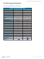
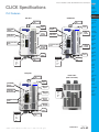
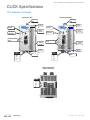
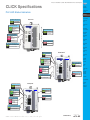
1
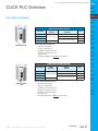
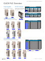
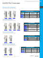
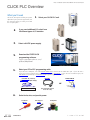
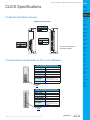
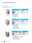
Prices as of October 15, 2015. Check Web site for most current prices. CLICK PLC Overview PLC Units The nineteen CLICK PLC units are available with different combinations of built-in I/O types. CLICK Basic PLC Units Part Number C0-00DD1-D C0-00DD2-D C0-00DR-D C0-00AR-D Basic PLC Inputs (8 points) Outputs (6 points) Price DC (0.1 A, 5-27 VDC, Sink) $69.00 DC (24 VDC, sink/source) DC (0.1 A, 24 VDC, Source) $69.00 Relay (1 A @ 6-27 VDC/6-240 VAC) AC (100-120 VAC) $79.00 $79.00 Basic PLC Unit Features: • Eight discrete input points • Six discrete output points • Two RS-232 communications ports CLICK Standard PLC Units Part Number C0-01DD1-D C0-01DD2-D C0-01DR-D C0-01AR-D Standard PLC Inputs (8 points) Outputs (6 points) Price DC (0.1 A, 5-24 VDC, Sink) $99.00 DC (24 VDC, sink/source) DC (0.1 A, 24 VDC, Source) AC (100-120 VAC) Relay (1 A @ 6-27 VDC/6-240 VAC) $99.00 $109.00 $109.00 Standard PLC Unit Features: • Eight discrete input points • Six discrete output points • Two RS-232 communications ports • One RS-485 communications port • Calendar / clock • Battery backup (Battery, p/n D2-BAT-1, sold separately) CLICK Analog PLC Units Part Number C0-02DD1-D C0-02DD2-D C0-02DR-D Analog PLC Inputs (4 points) DC (24 VDC, sink/source) Outputs (4 points) Analog Inputs, Outputs 2 channels in / 2 channels out; voltage (0-5 VDC) and current (4-20 mA) selectable, 12-bit resolution for Relay (1 A @ 6-27 VDC/6-240 VAC) both inputs and outputs Price DC (0.1 A, 5-24 VDC, Sink) $129.00 DC (0.1 A, 24 VDC, Source) $129.00 $139.00 Analog PLC Unit Features: • Four discrete input points and four discrete output points • Two analog input points and two analog output points (not isolated) • Two RS-232 communications ports • One RS-485 communications port • Calendar / clock • Battery backup (Battery, p/n D2-BAT-1, sold separately) Book 1 (14.3) eCL-16 CLICK PLCs 1-800-633-0405 Prices as of October 15, 2015. Check Web site for most current prices. CLICK PLC Overview Company Information Control Systems Overview CLICK PLC PLC Units (continued) Do-More PLCs Overview Do-More H2 PLC Do-More T1H PLC CLICK Ethernet Basic PLC Units Inputs (8 points) Part Number C0-10DD1E-D C0-10DD2E-D C0-10DRE-D C0-10ARE-D Ethernet Basic PLC DC (24 VDC, sink/source) AC (100-120 VAC) Outputs (6 points) Price DC (0.1 A, 5-27 VDC, Sink) $129.00 DC (0.1 A, 24 VDC, Source) $129.00 Relay (1A @ 6-27 VDC/6-240 VAC) $129.00 $139.00 DirectLOGIC PLCs Overview DirectLOGIC DL05/06 DirectLOGIC DL105 DirectLOGIC DL205 Ethernet Basic PLC Unit Features: • Eight discrete input points • Six discrete output points • One Ethernet communications port • One RS-232 communications port • Calendar / clock • Battery backup (Battery, p/n D2-BAT-1, sold separately) DirectLOGIC DL305 DirectLOGIC DL405 Productivity 2000 Productivity 3000 CLICK Ethernet Standard PLC Units Inputs (8 points) Part Number C0-11DD1E-D C0-11DD2E-D C0-11DRE-D C0-11ARE-D Ethernet Standard PLC DC (24 VDC, sink/source) AC (100-120 VAC) Universal Field I/O Outputs (6 points) Price Software DC (0.1 A, 5-27 VDC, Sink) $149.00 C-More HMI DC (0.1 A, 24 VDC, Source) $149.00 Relay (1 A @ 6-27 VDC/6-240 VAC) $159.00 $159.00 Ethernet Standard PLC Unit Features: • Eight discrete input points • Six discrete output points • One Ethernet communications port • One RS-232 communications port • One RS-485 communications port • Calendar / clock • Battery backup (Battery, p/n D2-BAT-1, sold separately) ViewMarq Industrial Marquees Other HMI Communications Appendix Book 1 Terms and Conditions Book 1 (14.3) www.automationdirect.com/click-plc C-More Micro HMI CLICK PLCs eCL-17 Prices as of October 15, 2015. Check Web site for most current prices. CLICK PLC Overview Power Supplies DC-DC Converter Two power supplies are offered. This DC-to-DC converter can be used to power the CLICK PLC from 12 VDC input power. CLICK Power Supplies Part Number C0-00AC C0-01AC Input Voltage Output Current Price 85-264 VAC 0.5A @ 24 VDC $29.00 85-264 VAC 1.3A @ 24 VDC $39.00 12 VDC-to-24 VDC Converter C0-00AC C0-01AC Discrete Input Modules Part Number Input Voltage Output Current Price PSP24-DC12-1 9.5-18 VDC 1.0A @ 24 VDC $78.00 PSP24-DC12-1 There are six discrete input modules available. CLICK Discrete Input Modules C0-08ND3 C0-08NE3 C0-08ND3-1 C0-16ND3 Part Number C0-08ND3 C0-08ND3-1 C0-16ND3 C0-08NE3 C0-16NE3 C0-08NA Inputs Price DC (8 pts, 12-27 VDC) $33.00 DC (8 pts, 3.3-5 VDC) $33.00 DC (16 pts, 24 VDC) $45.00 AC/DC (8 pts, 24 VAC/VDC) $35.00 AC/DC (16 pts, 24 VAC/VDC) $49.00 AC (8 pts, 100-120 VAC) $40.00 C0-08NA C0-16NE3 Discrete Output Modules There are seven discrete output modules available. C0-08TD1 C0-08TD2 CLICK Discrete Output Modules C0-16TD1 Part Number Outputs DC (8 pts, 0.3 A @ 3.3-27 VDC, Sink) C0-08TD1 DC (8 pts, 0.3 A @ 12-24 VDC, Source) C0-08TD2 DC (16 pts, 0.1 A @ 5-27 VDC, Sink) C0-16TD1 DC (16 pts, 0.1 A @ 12-24 VDC, Source) C0-16TD2 AC (8 pts, 0.3A @ 17-240 VAC) C0-08TA Relay (4 pts, 7A @ 6-27 VDC/6-240 VAC) C0-04TRS* Relay (8 pts, 1A @ 6-27 VDC/6-240 VAC) C0-08TR Price $35.00 $35.00 $45.00 $45.00 $50.00 $44.00 $40.00 *To drive more than a 7A load or to use replaceable relays, consider using a C0-16TD1 output module with a ZL-RRL16-24-1 ZIPLink relay module and the correct ZIPLink cable (see Wiring System for CLICK PLCs later in this section). C0-16TD2 C0-08TA C0-04TRS C0-08TR Book 1 (14.3) eCL-18 CLICK PLCs 1-800-633-0405 Prices as of October 15, 2015. Check Web site for most current prices. CLICK PLC Overview Company Information Control Systems Overview CLICK PLC Discrete Combo I/O Modules Do-More PLCs Overview There are three discrete combo modules available. Do-More H2 PLC Discrete Combo I/O Modules Part Number Input Type Output Type Price DC (8 pts, 24 VDC) DC (8 pts, 0.1A @ 5-27 VDC, Sink) $59.00 DC (8 pts, 24 VDC) DC (8 pts, 0.1A @ 12-24 VDC, Source) $59.00 DC (4 pts, 12-24 VDC) Relay (4 pts, 1A @ 6.25-24 VDC / 6-240 VAC $49.00 C0-16CDD1 C0-16CDD2 C0-08CDR C0-16CDD1 C0-16CDD2 DirectLOGIC DL305 Analog Input Modules Part Number C0-04AD-1 C0-04AD-2 C0-04RTD C0-04RTD C0-04THM C0-04THM DirectLOGIC DL405 Analog Input Types Price 4 channel, current (0-20 mA), 13 bit $89.00 4 channel, voltage (0-10 V), 13 bit $89.00 4 channel RTD input (0.1 degree °C/°F resolution), or resistive input (0 - 3125q, 0.1q or 0.01q resolution) 4 channel thermocouple input (0.1 degree °C/°F resolution), or voltage input (-156.25 mV to 1.25 V, 16 bit) $149.00 $149.00 Universal Field I/O Software ViewMarq Industrial Marquees Analog Output Modules Part Number C0-04DA-1 C0-04DA-2 Analog Output Types Price Other HMI 4 channel, current sourcing (4-20 mA), 12 bit $119.00 Communications 4 channel, voltage (0-10 V), 12 bit $119.00 Appendix Book 1 Terms and Conditions C0-04DA-2 Analog Combo I/O Modules There are two analog combo modules available. Analog Combo I/O Modules Part Number C0-4AD2DA-1 C0-4AD2DA-2 Analog Input Type Analog Output Type Price 4 channel, current (0-20 mA), 13 bit 4 channel, voltage (0-10 V), 13 bit 2 channel, current sourcing (4-20 mA), 12 bit 2 channel, voltage (0-10 V), 12 bit $149.00 $149.00 C0-4AD2DA-2 Book 1 (14.3) www.automationdirect.com/click-plc Productivity 3000 C-More Micro HMI There are two analog output modules available. C0-4AD2DA-1 Productivity 2000 C-More HMI Analog Output Modules C0-04DA-1 DirectLOGIC DL05/06 DirectLOGIC DL205 There are four analog input modules available. C0-04AD-2 DirectLOGIC PLCs Overview DirectLOGIC DL105 C0-08CDR Analog Input Modules C0-04AD-1 Do-More T1H PLC CLICK PLCs eCL-19 Prices as of October 15, 2015. Check Web site for most current prices. CLICK PLC Overview What you’ll need Of course, what you’ll need for your system depends on your particular application, but this overview shows you what you’ll need for a simple system. 2. 1. Select your CLICK PLC unit. If you need additional I/O, select from 24 different types of I/O modules. 3. Select a 24 VDC power supply. 4. Download the FREE CLICK programming software. or support.automationdirect.com/ products/clickplcs.html 5. Select your PC-to-PLC programming cable. If your PC has a USB port, use cable EA-MG-PGM-CBL to connect to the CLICK PLC port. If your PC has a 9-pin serial communications port, use programming cable D2-DSCBL. If your PC has an Ethernet port, use C5E-STPYL-C3 (crossover) or C5E-STPYL-S3 (straight through) Ethernet cable. D2-DSCBL C5E-STPYL-C3 (crossover) C5E-STPYL-S3 (straight through) EA-MG-PGM-CBL or For Ethernet PLC Unit 6. (PC requires RS-232 port to use this cable) Select tools, wire, and provide power. Screwdriver DN-SS1 Wire Strippers DN-WS Hookup Wire Book 1 (14.3) eCL-20 CLICK PLCs 1-800-633-0405 Prices as of October 15, 2015. Check Web site for most current prices. CLICK Programming Software Company Information Control Systems Overview FREE Software! CLICK programming software can be downloaded at no charge. The CLICK programming software is designed to be a user-friendly application, and the tools, layout, and software interaction provide ease-of-use and quick learning. Main window CLICK PLC The Main Window is displayed when the program opens. It is divided into Menus, Toolbars, and Windows that work together to make project development as simple as possible. Do-More PLCs Overview Do-More T1H PLC DirectLOGIC PLCs Overview The simple operation of this software allows users to quickly develop a ladder logic program. The online help file provides information that will help you get acquainted with the software quickly. DirectLOGIC DL05/06 DirectLOGIC DL105 PC Requirements CLICK PLC Windows-based programming software works with Windows® 2000 Service Pack 4, XP Home or Professional, Vista (32 bit), Windows 7 (32 bit), Windows 8 &10 (32 bit and 64 bit for both). These are the minimum system requirements: • Personal Computer with a 333 MHz (2000 SP4/XP), 800 MHz (Vista), 1 GHz (Windows 7, Windows 8 & 10) or higher processor (PLC) clock speed recommended; Intel Pentium/Celeron family or AMD K6 Athlon/Duron family, or compatible processor recommended • S VGA 1024x768 pixels resolution. (1280x1024 pixels resolution recommended) • 150MB free hard-disk space • Memory (free RAM): 128MB (512MB recommended) for 2000 SP4/XP; 512 MB (1 GB recommended) for Vista, 1 GB (2 GB for 64 bit) for Windows 7 and Windows 8 • CD-ROM or DVD drive (only if installing software from a CD-ROM) • 9-pin serial port or USB port for project transfer to PLC (USB port communications also requires USB-to-serial converter. Note: USB-to-serial convertor does not support XP Mode of Windows 7.) Do-More H2 PLC DirectLOGIC DL205 DirectLOGIC DL305 DirectLOGIC DL405 Productivity 2000 Productivity 3000 Universal Field I/O Software Navigation Window Instruction List Window Ladder Edit Window C-More Micro HMI ViewMarq Industrial Marquees Other HMI Communications Appendix Book 1 The CLICK programming software can be downloaded free at the AutomationDirect Web site: Terms and Conditions support.automationdirect.com/ products/clickplcs.html C0-PGMSW Free Download The programming software is also available for purchase on a CD-ROM for $10.00 Book 1 (14.3) www.automationdirect.com/click-plc C-More HMI CLICK PLCs eCL-21 Prices as of October 15, 2015. Check Web site for most current prices. CLICK Programming Software Instructions The easy-to-use instructions are described in the CLICK programming software online help file. Powerful Features! Address Picker The Address Picker is a powerful multi-function memory table which can be used to assign nicknames, create address comments, and establish initial values for specific memory locations. It can assign specific memory locations to be retentive during power outages. The Address Picker also has powerful tools for sorting the memory table and making it easier to use. CLICK programming software has amazingly powerful features for a free software product, such as • Address picker • Separate subroutine programs • Separate interrupt programs • Color r ung comment feature • Project loader • Documentation is stored within the PLC Memory Subroutine Programs Subroutine programs can be created and named to isolate a body of program code that is run selectively. You can run up to 986 subroutine programs. Interrupt Programs Interrupt programs are created and named. The Basic and Standard PLC Units (with or without Ethernet) support up to 12 interrupt programs. The Analog PLC Units support up to 8 interrupt programs. Book 1 (14.3) eCL-22 CLICK PLCs 1-800-633-0405 Prices as of October 15, 2015. Check Web site for most current prices. CLICK Programming Software Company Information Control Systems Overview CLICK PLC Color Rung Comment Do-More PLCs Overview Easily create and edit rung comments with colors and three text styles. Comments are stored in the PLC memory for future reference. Do-More H2 PLC Do-More T1H PLC DirectLOGIC PLCs Overview DirectLOGIC DL05/06 DirectLOGIC DL105 DirectLOGIC DL205 DirectLOGIC DL305 DirectLOGIC DL405 Productivity 2000 Project Loader Productivity 3000 The CLICK programming software can export the CLICK project in an encrypted format. The exported file can be sent to the end user. Then the end user can download the file into the CLICK PLC with the tool called Project Loader. Universal Field I/O Software C-More HMI C-More Micro HMI ViewMarq Industrial Marquees Other HMI Communications Appendix Book 1 Terms and Conditions NOTE: Project Loader is a separate program from the CLICK programming software, but it is installed on the PC when the CLICK programming software is installed. Book 1 (14.3) www.automationdirect.com/click-plc CLICK PLCs eCL-23 Prices as of October 15, 2015. Check Web site for most current prices. Product Dimensions and Installation Ground Braid Copper Lugs It is important to understand the installation requirements for your CLICK system. Your knowledge of these requirements will help ensure that your system operates within its environmental and electrical limits. Panel or Single Point Ground Panel Star Washers Plan for Safety This catalog should never be used as a replacement for the user manual. Star Washers 2 in. 50.8 mm minimum You can purchase, download free, or view online the user manuals for these products. Manual C0-USER-M is the user manual for the CLICK PLC. The user manual contains important safety information that must be followed. The system installation should comply with all appropriate electrical codes and standards. 2 in. 50.8mm minimum 3 in. 76.2 mm minimum NOTE: There is a mimimum clearance requirement of 2 inches(51 mm) between the CLICK PLC and the panel door or any devices mounted in the panel door. The same clearance is required between the PLC and any side of the enclosure. A minimum clearance of 3 inches (76 mm) is required between the PLC and a wireway or any heat producing device. PORT1 TX1 RX1 TX2 RX2 PORT2 RUN PWR RUN ERR CLICK PLCs must be mounted properly to ensure ample airflow for cooling purposes. It is important to follow the unit orientation requirements and to verify that the PLC’s dimensions are compatible with your application. Notice particularly the grounding requirements and the recommended cabinet clearances. STOP Mounting Orientation Air Flow Book 1 (14.3) eCL-24 CLICK PLCs 1-800-633-0405 Prices as of October 15, 2015. Check Web site for most current prices. Product Dimensions and Installation Company Information Control Systems Overview Latch tabs Connecting the Modules Together CLICK PLC 3 Do-More PLCs Overview Connecting Modules CLICK PLCs, I/O modules and power supplies connect together using the extension ports that are located on the side panels of the modules (no PLC backplane/base required). 1. R emove extension port covers and slide the latch tabs forward. 2. A lign the module pins and connection plug, and press the I/O module onto the right side of the PLC. 3. S lide the latch tabs backward to lock the modules together. Do-More H2 PLC 2 Do-More T1H PLC DirectLOGIC PLCs Overview DirectLOGIC DL05/06 DirectLOGIC DL105 1 DirectLOGIC DL205 DirectLOGIC DL305 DirectLOGIC DL405 Productivity 2000 Supports up to eight I/O modules Productivity 3000 Universal Field I/O DIN Rail Mounting Mounting Surface Mounting Upper Mounting Tab Software C-More HMI The CLICK PLC system, which includes the CLICK power supplies, PLC units, and I/O modules, can be mounted in one of two ways. 1. D IN rail mounted 2. S urface mounted using the built-in upper and lower mounting tabs. C-More Micro HMI ViewMarq Industrial Marquees Other HMI Pull tab down. Push tab up until... Lower Mounting Tab Click Communications Appendix Book 1 Power Supply Module Unit Dimensions The dimensional drawings here and on the next page show the outside dimensions of the CLICK power suppy, PLC, and I/O modules. The CLICK PLC system is designed to be mounted on standard 35mm DIN rail, or it can be surface mounted. Allow proper spacing from components within an enclosure. 2.6 [0.102] PLC Unit 34.9 [1.37] 53.5 [2.11] Unit Dimensions mm [inches] I/O Module 27 [1.06] 13.5 [0.46] Terms and Conditions 75 [2.95] 85 5 [3.35] .35] 5 other Maximum system: 4 [0.16] Power Supply + PLC + 8 I/O modules. " 9.2 [0.36] www.automationdirect.com/click-plc 9.4 [0.37] Book 1 (14.3) CLICK PLCs eCL-25 Prices as of October 15, 2015. Check Web site for most current prices. Product Dimensions and Installation Unit Dimensions Power Supply mm [inches] PLC Unit I/O Module Book 1 (14.3) eCL-26 CLICK PLCs 1-800-633-0405 Prices as of October 15, 2015. Check Web site for most current prices. Networking the CLICK PLC Company Information Control Systems Overview Built-in Communications Ports Port 1 & 2 LED Status Indicators TX1 and TX2 (Green) STOP Off The Comm Port is not sending data. PORT1 TX1 RX1 TX2 RX1 and RX2 (Green) RX2 On The Comm Port is receiving data. PORT2 Off The Comm Port is not receiving data. Port 1, 2, & 3 LED Status Indicators RUN ERR TX1, TX2 and TX3 (Green) PORT1 TX1 On The Comm Port is sending data. RX1 Off The Comm Port is not sending data. TX2 RX2 PORT2 RX1, RX2 and RX3 (Green) On The Comm Port is receiving data. Off The Comm Port is not receiving data. PORT3 RS-485 TX3 RX3 Do-More T1H PLC Com Port 3 Standard and Analog PLCs Basic PLC Use: Programming Port / Serial Communications (Slave only) Physical: 6 pin, RJ12, RS-232 Communication speed (baud): 38400 (fixed) Parity: Odd Station Address: 1 Data length: 8 bits Stop bit: 1 Protocol: Modbus RTU (slave only) Use: Serial Communications Physical: 6 pin, RJ12, RS-232 Communication speed (baud): 1200, 2400, 4800, 9600, 19200, 38400, 57600, 115200 Parity: odd, even, none Station Address: 1 to 247 Data length: 8 bits (Modbus RTU) or 7, 8 bits (ASCII) Stop bit: 1,2 Protocol: Modbus RTU (master/slave) or ASCII in/out Use: Serial Communications Physical: 3 pin, RS-485 Communication speed (baud): 1200, 2400, 4800, 9600, 19200, 38400, 57600, 115200 Parity: odd, even, none Station Address: 1 to 247 Data length: 8 bits (Modbus RTU) or 7, 8 bits ( ASCII) Stop bit: 1,2 Protocol: Modbus RTU (master/slave) or ASCII in/out Default - Port 1 Port 1 Pin Descriptions 6 pin RJ12 Phone Type Jack 1 Com Port 1 Specifications Com Port 3 Specifications Standard and Analog PLCs Do-More H2 PLC Com Port 2 Com Port 2 Com Port 2 Specifications Basic PLCs On The Comm Port is sending data. Com Port 1 6 There are LED indicators located to the left of each communications port to indicate when the port is transmitting or receiving. Com Port 1 1 2 3 4 5 6 0V 5V RXD TXD NC 0V Power (-) connection (GND) Power (+) connection Receive data (RS-232) Transmit data (RS-232) No connection Power (-) connection (GND) Port 2 Port 2 Pin Descriptions 6 pin RJ12 Phone Type Jack 38400 Odd 1 1 2 3 4 5 6 0V 5V RXD TXD RTS 0V Power (-) connection (GND) Power (+) connection Receive data (RS-232) Transmit data (RS-232) Request to send Power (-) connection (GND) 8 bits Port 3 RS-485 Port 3 Pin Descriptions 1 2 3 Signal A (RS-485) Signal B - (minus) (RS-485) Logic LG Ground(0 V) + (plus) DirectLOGIC DL305 Productivity 2000 Productivity 3000 Universal Field I/O Software Other HMI Communications Appendix Book 1 Terms and Conditions 8 bits 1 Modbus RTU Port Setup Use CLICK programming software to easily configure the communications ports. Book 1 (14.3) www.automationdirect.com/click-plc DirectLOGIC DL205 ViewMarq Industrial Marquees Default Odd 1 DirectLOGIC DL105 C-More Micro HMI Modbus RTU 38400 DirectLOGIC DL05/06 C-More HMI 1 - DirectLOGIC PLCs Overview DirectLOGIC DL405 1 LED Status Indicators Do-More PLCs Overview 6 Basic, Standard and Analog PLCs have two built-in RS-232 communications ports. Standard and Analog PLCs also have one built-in RS-485 communications port. One RS-232 port supports the Modbus RTU protocol only and can be used as the programming port. The other ports support either Modbus RTU or ASCII protocol. Both RS-232 ports supply 5V DC, so you can connect a monochrome C-more Micro HMI panel without an additional power supply. CLICK PLC CLICK PLCs eCL-27 Networking the CLICK PLC Prices as of October 15, 2015. Check Web site for most current prices. Built-in Communications Ports LNK/ACT LED (Green) Blink Communicating Off RU R RUN PWR RUN S STOP ERR PORT1 Disconnected from the network LNK/ACT ETHER NET 100MBIT 100MBIT LED (Orange) PORT2 On Communicating at 100Mbps Off Communicating at 10Mbps or disconnected from the network TX2 RX2 RS-232 RS 232 Ethernet Standard PLCs Port 1 Com Port 1 Specifications Port 1 Pin Descriptions 8 pin RJ45 Phone 8 pin RJ45 Type Jack 1 Use: Programming and Ethernet Communication Physical: 8 pin, RJ45, Ethernet Communication speed (Mbps): 10/100 Protocol: Modbus TCP Use: Serial Communication Physical: 6 pin, RJ12, RS-232 Communication speed (baud): 2400, 4800, 9600, 19200, 38400, 57600, 115200 Parity: odd, even, none Station Address: 1 to 247 Data length: 8 bits (Modbus RTU) or 7, 8 bits (ASCII) Stop bit: 1,2 Protocol: Modbus RTU (master/slave) or ASCII in/out Port 11 & & 22 LED Port LED StatusIndicators Indicators Status Connected to the network Com Port 3 Ethernet Basic PLC Com Port 2 Specifications Ethernet Basic PLCs On Com Port 2 Com Port 2 8 There are LED indicators located to the left of each communication port to indicate when the port is transmitting or receiving. Com Port 1 Default - 1 2 3 4 5 6 7 8 Port 2 pin RJ12 RJ12 Phone 66pin Phone Type Jack Type Jack 38400 1 LED Status Indicators Com Port 1 Odd 1 6 Ethernet Basic and Standard PLCs have one built-in Ethernet communications port and one RS-232 communications port. Ethernet Standard PLCs also have one built-in RS-485 communications port. The Ethernet port supports the Modbus TCP protocol. The RS-232 and RS-485 ports support either Modbus RTU or ASCII protocol. The RS-232 port supplies 5 VDC, so you can connect a monochrome C-more Micro HMI panel without an additional power supply. TX+ TXRX+ NC NC RXNC NC Transmit Data (+) Transmit Data (-) Receive data (+) Not connected Not connected Receive Data (-) No connection No connection Port 2 Pin Descriptions 1 2 3 4 5 6 0V 5V RXD TXD RTS 0V Power (-) connection (GND) Power (+) connection Receive data (RS-232) Transmit data (RS-232) Request to send Power (-) connection (GND) 8 bits 1 Modbus RTU TX2 (Green) On The Comm Port is sending data. Off The Comm Port is not sending data. Com Port 3 Specifications RX2 (Green) On The Comm Port is receiving data. Off The Comm Port is not receiving data. Ethernet Standard PLCs Port 1, 2 & 3 LED Port 1, Indicators 2, & 3 LED Status Status Indicators LNK/ACT LED (Green) On Connected to the network Blink Communicating Off Disconnected from the network RUN ERR 100MBIT LED (Orange) On Communicating at 100Mbps Off Communicating at 10Mbps or disconnected from the network STOP PORT1 38400 Port 3 Pin Descriptions 1 2 3 Signal A (RS-485) Signal B - (minus) (RS-485) Logic LG Ground(0 V) + (plus) Odd 1 8 bits 1 Modbus RTU PORT2 Port Setup RX2 RS-232 On The Comm Port is sending data. PORT3 Off The Comm Port is not sending data. TX3 RX2 and RX3 (Green) - Port 3 RS-485 RS-485 LNK/ACT ETHER NET 100MBIT TX2 TX2 and TX3 (Green) Use: Serial Communication Physical: 3 pin, RS-485 Communication speed (baud): 2400, 4800, 9600, 19200, 38400, 57600, 115200 Parity: odd, even, none Station Address: 1 to 247 Data length: 8 bits (Modbus RTU) or 7, 8 bits ( ASCII) Stop bit: 1,2 Protocol: Modbus RTU (master/slave) or ASCII in/out Default RX3 RS-485 + _ LG Use CLICK programming software to easily configure the communication ports. On The Comm Port is receiving data. Off The Comm Port is not receiving data. Book 1 (14.3) eCL-28 CLICK PLCs 1-800-633-0405 Prices as of October 15, 2015. Check Web site for most current prices. Networking the CLICK PLC Company Information Control Systems Overview CLICK PLC Typical Communication Applications Do-More PLCs Overview The diagrams on these three pages illustrate the typical uses for the CLICK PLC’s communication ports. Port 1 (RS-232) – Modbus RTU Slave Mode Only Do-More H2 PLC Do-More T1H PLC DirectLOGIC PLCs Overview Port 1 DirectLOGIC DL05/06 C-more and C-more Micro-Graphic Panel PC Another CLICK PLC DirectLOGIC DL105 Other Devices Supporting Modbus RTU Master Mode Basic, Standard and Analog PLC DirectLOGIC DL205 DirectLOGIC DL305 DirectLOGIC DL405 C-more Micro-Graphic panels (monochrome models only) can get 5 VDC power from Com port 1 or 2. Example Productivity 2000 C-more 3 Inch Micro-Graphic Panel Productivity 3000 Universal Field I/O CLICK PLC Port 1 Software C-More HMI DV-1000CBL serial cable C-More Micro HMI The Color Micro-Graphic panel or the second Monochrome Micro-Graphic panel needs a separate 24 VDC power source (see the note below). ViewMarq Industrial Marquees Port 1 or 2 Other HMI NOTE: CLICK’s (RS-232) Port 1 and Port 2 can provide 5 VDC power to the panel, but not at the same time. If a C-more Micro-Graphic panel is connected to both ports, then at least one of the panels must be powered by a C-more Micro DC power adapter, EA-MG-P1 or EA-MG-SP1, or another 24 VDC power source. Color C-more Micro-Graphic panels must also be powered from a separate 24 VDC source. Do not use the following Direct LOGIC devices with CLICK’s Port 1 or 2: Warning: The following DirectLOGIC PLC devices cannot be used with a CLICK PLC’s Port 1 or Port 2: Handheld Programmer for DL05, DL06, DL105, DL205 & D3-350 CPUs, p/n D2-HPP Handheld Programmer for DL405 CPUs, p/n D4-HPP-1 Timer/Counter Access for DL05, DL06, DL105, DL205, DL405 & D3-350 CPUs, p/n DV-1000 D2-HPP D4-HPP-1 DV-1000 Book 1 (14.3) www.automationdirect.com/click-plc CLICK PLCs eCL-29 Communications Appendix Book 1 Terms and Conditions Prices as of October 15, 2015. Check Web site for most current prices. Networking the CLICK PLC Port 1 (Ethernet) – Modbus TCP Modbus TCP Client (Master) Devices Port 1 PC All CLICK Ethernet PLCs Another CLICK Ethernet PLC Other Devices Supporting Modbus TCP Client Mode C-more Panel Modbus TCP Server (Slave) Devices Other Devices Supporting Modbus TCP Server Mode ViewMarq Display Another CLICK Ethernet PLC SR55 Soft Starter GS1 Drive GS3 Drive Book 1 (14.3) eCL-30 CLICK PLCs 1-800-633-0405 Prices as of October 15, 2015. Check Web site for most current prices. Networking the CLICK PLC Company Information Control Systems Overview CLICK PLC Port 2 (RS-232) – Modbus RTU or ASCII Port 3 (RS-485; Standard, Ethernet Standard and Analog PLCs Only) – Modbus RTU or ASCII All PLCs have RS-232 port 2, but only Standard, Analog and Ethernet Standard PLCs have RS-485 port 3. Ports 2 and 3 allow networking to similar devices. Do-More PLCs Overview Do-More H2 PLC Do-More T1H PLC Port 2 Port 2 DirectLOGIC PLCs Overview Port 3 Modbus RTU Modbus RTU Master Devices DirectLOGIC DL05/06 DirectLOGIC DL105 DirectLOGIC DL205 DirectLOGIC DL305 DirectLOGIC DL405 Basic PLC Ethernet Basic PLC Productivity 2000 Standard or Analog PLC Ethernet Standard PLC PC Another CLICK PLC Productivity 3000 Universal Field I/O See Note on previous page about connecting a C-more Micro-Graphic panel to Port 1 or 2. Software C-More HMI C-more and C-more Micro-Graphic Panel Other Devices Supporting Modbus RTU Master Mode ASCII Communications Appendix Book 1 Other devices that can send ASCII data. Terms and Conditions Modbus RTU Slave Devices Weigh Scale Other Devices Supporting Modbus RTU Slave Mode Devices that RECEIVE ASCII messages Serial Printer ViewMarq Display ViewMarq Industrial Marquees Other HMI Devices that SEND ASCII messages Barcode Reader C-More Micro HMI Other devices that can receive ASCII data. Another CLICK PLC SOLO Temperature Controller (CLICK Port 3 Only) Book 1 (14.3) www.automationdirect.com/click-plc CLICK PLCs eCL-31 Prices as of October 15, 2015. Check Web site for most current prices. Power Supplies Power Supplies The CLICK PLC family offers two 24 VDC power supplies. They are identical except for the output current. It is not mandatory to use one of these CLICK power supplies for the CLICK PLC system. You can use any other 24 VDC power supply that Automationdirect.com offers, including the PSP24-DC12-1 12 VDC to 24 VDC converter shown below. C0-00AC Power Supply Limited auxiliary AC power supply allows you to power the 24 VDC CLICK C0 series PLCs with 100-240 VAC supply power. The 0.5A DC power supply is capable of controlling the PLC plus a limited configuration based on the power budget of each I/O module. The C0-00AC is a lowcost solution for applications requiring only minimal I/O and power consumption. This power supply will not support a fully-populated CLICK PLC system with all possible I/O module combinations. C0-01AC Power Supply Expanded auxiliary AC power supply allows you to power the 24 VDC CLICK C0 series PLCs with 100-240 VAC supply power. The 1.3A DC power supply is capable of supporting a fully-populated CLICK PLC system with all possible I/O module combinations, with no concerns for exceeding the power budget. PSP24-DC12-1 DC-DC Converter With this DC-DC converter you can operate the CLICK PLC with 12 VDC input power. CLICK 24 VDC Power Supply Ratings Part Number C0-00AC C0-01AC Output Current Price 0.5 A 1.3 A $29.00 $39.00 C0-00AC C0-00AC Power Supply Specifications Input Voltage Range Input Frequency Input Current (typical) Inrush Current Output Voltage Range Output Current Over Current Protection Weight 85-264 VAC 47-63 Hz 0.3 A @ 100 VAC, 0.2 A @ 200 VAC 30 A 23-25 VDC 0.5 A @ 0.65 A (automatic recovery) 5.3 oz (150g) C0-01AC Power Supply Specifications Input Voltage Range Input Frequency Input Current (typical) Inrush Current Output Voltage Range Output Current Over Current Protection Weight 85-264 VAC 47-63 Hz 0.9 A @ 100 VAC, 0.6 A @ 200 VAC 30 A 23-25 VDC 1.3 A @ 1.6 A (automatic recovery) 6.0 oz (170g) 85-264 VAC Power Source Input Terminals PSP24-DC12-1 DC-DC Converter Specifications Input Voltage Range Input Power (no load) Startup Voltage Undervoltage Shutdown Output Voltage Range Output Current Short Circuit Protection Weight CLICK Power Supply 24 VDC Output Power Terminals (for CLICK PLC, I/O or field device, etc.) 9.5-18 VDC 1.0 W max. C0-01AC 8.4 VDC 7.6 VDC 24-28 VDC (adjustable) 1.0 A Current limited at 110% typical 7.5 oz (213g) CLICK PLC 24 VDC Output Power Terminals (for CLICK PLC, I/O or field device, etc.) 85-264 VAC Power Source Input Terminals PSP24-DC12-1 24V 0V G 24 VDC power is supplied to the PLC unit through wiring connected from the power supply output to the 4-pin 24 VDC input connector located on the bottom of the PLC unit. Book 1 (14.3) eCL-32 CLICK PLCs 1-800-633-0405 Prices as of October 15, 2015. Check Web site for most current prices. Power Budgeting Company Information Control Systems Overview Power Budgeting There are two areas to be considered when determining the power required to operate a CLICK PLC system. The first area is the power required by the CLICK PLC, along with the internal logic side power that the CPU provides to its own I/O and any connected I/O modules that are powered through the PLC expansion port; plus any device, such as a C-more Micro-Graphic panel, that is powered through one of the communications ports. It is strongly recommended that the power source for the logic side be separate from the power source for the field side to help eliminate possible electrical noise. The second area is the power required by all externally connected I/O devices. This should be viewed as the field side power required. The field side power is dependent on the voltage used for a particular input or output device as it relates to the wired I/O point, and the calculated load rating of the connected device. Refer to the Power Budgeting example shown on the following page. The table shows required current for a CLICK PLC, two I/O modules, and a C-more Micro. Use the total amperage values to select the properly sized power supply. Power budgeting requires the calculation of the total current the 24 VDC power source needs to provide to CLICK’s logic side, and also a separate calculation of the total current required for all devices operating from the field side of the PLC system. CLICK PLC Do-More PLCs Overview Do-More H2 PLC Do-More T1H PLC DirectLOGIC PLCs Overview DirectLOGIC DL05/06 DirectLOGIC DL105 DirectLOGIC DL205 DirectLOGIC DL305 DirectLOGIC DL405 Productivity 2000 Productivity 3000 CLICK 24 VDC Power Supply C0-00AC or C0-01AC Other 24 VDC Power Supply Example: PSP24-60S Universal Field I/O Software PLC Current Consumption (mA) Part Number Power Budget External 24 VDC 24 VDC (logic side) (field side) Basic PLC Units 120 60 C0-00DD1-D C0-00DD2-D 120 0 C0-00DR-D C0-00AR-D Standard PLC Units 140 60 C0-01DD1-D C0-01DD2-D C0-01DR-D 140 0 C0-01AR-D Analog PLC Units 140 60 C0-02DD1-D C0-02DD2-D 140 0 C0-02DR-D Ethernet Basic PLC Units 120 60 C0-10DD1E-D C0-10DD2E-D 120 0 C0-10DRE-D C0-10ARE-D Ethernet Standard PLC Units 140 60 C0-11DD1E-D C0-11DD2E-D 140 0 C0-11DRE-D C0-11ARE-D I/O Module Current Consumption (mA) Power Budget External 24 VDC 24 VDC (logic side) (field side) Discrete Input Modules Part Number 30 C0-08ND3 30 C0-08ND3-1 40 C0-16ND3 30 C0-08NE3 40 C0-16NE3 30 C0-08NA Discrete Output Modules 50 C0-08TD1 50 C0-08TD2 80 C0-16TD1 80 C0-16TD2 80 C0-08TA 100 C0-04TRS 100 C0-08TR 0 0 0 0 0 0 15 0 100 0 0 0 0 I/O Module Current Consumption (continued) (mA) Power Budget External Part Number 24 VDC 24 VDC (logic side) (field side) Discrete Combo I/O Modules 80 50 C0-16CDD1 80 0 C0-16CDD2 80 0 C0-08CDR Analog Input Modules 20 65 C0-04AD-1 23 65 C0-04AD-2 25 0 C0-04RTD 25 0 C0-04THM Analog Output Modules 20 145 C0-04DA-1 20 85 C0-04DA-2 Analog Combo I/O Modules 25 75 C0-4AD2DA-1 20 65 C0-4AD2DA-2 C-more Micro-Graphic Panel Monochrome 90 0 only Book 1 (14.3) www.automationdirect.com/click-plc CLICK PLCs eCL-33 C-More HMI C-More Micro HMI ViewMarq Industrial Marquees Other HMI Communications Appendix Book 1 Terms and Conditions Prices as of October 15, 2015. Check Web site for most current prices. Power Budgeting Power Budgeting Using the CLICK Programming Software The CLICK Programming software can also be used for power budgeting. Based on the amperage rating of the power supply selected in the first column, your power budget is calculated by subtracting each consecutive module’s power consumption from the total available power budget. If you exceed the maximum allowable power consumption the power budget row is highlighted in red. Power Budgeting Example Current Consumption (mA) Example Part Number C0-00DD1-D C0-16ND3 C0-16TD1 C-more Micro Total: Power Budget External 24 VDC 24 VDC (logic side) (field side) 120 40 80 90 330 60 0 100 0 160* * Add in calculated load of connected I/O devices. Power Supply (C0-01AC) PLC Module (C0-00DD1-D) I/O Module (C0-16ND3) Port 1 or Port 2 I/O Module (C0-16TD1) C-more Micro-Graphic Panel Only monochrome models can be powered from port 1 or 2. Book 1 (14.3) eCL-34 CLICK PLCs 1-800-633-0405 Prices as of October 15, 2015. Check Web site for most current prices. Choosing a PLC Unit Company Information Control Systems Overview Five types of CLICK PLC units are available: • Basic PLCs with discrete-only inputs and outputs. • Standard PLCs with discrete-only inputs and outputs, plus an extra communications port and battery backup. • Analog PLCs with both discrete and analog inputs and outputs, plus an extra communications port and battery backup. • Ethernet Basic PLCs with discrete-only inputs and outputs. • Ethernet Standard PLCs with discrete-only inputs and outputs, plus an extra communications port and battery backup. CLICK PLC Basic PLC PLC Mode Switch Do-More PLCs Overview C0-00DD1-D 8 Discrete Input Points LED Status Indicators Do-More T1H PLC DirectLOGIC PLCs Overview Communication Ports 6 Discrete Output Points All CLICK PLC units offer the same performance, use the same instruction set, and support all optional I/O modules. Each PLC I/O can be easily expanded in the future with optional I/O modules as the need arises. The tables on the right list the part numbers and the various I/O type combinations. Standard PLC Units Standard PLC modules also have an RS-485 port for Modbus and ASCII communications, and the battery backup feature which will retain the data in SRAM for 5 years (battery sold separately; part no. D2-BAT-1). DirectLOGIC DL05/06 DirectLOGIC DL105 DirectLOGIC DL205 Basic and Standard PLC Units The Basic and Standard CLICK PLC units are available with different combinations of built-in I/O types (i.e. DC input/DC output, DC input/relay output, and AC input/relay output). With the 14 builtin I/O points (8 inputs/6 outputs), the PLC can be used as a ready-to-go PLC control system without any additional I/O modules. The PLC unit only requires a 24 VDC power supply. Do-More H2 PLC DirectLOGIC DL305 DirectLOGIC DL405 Basic PLCs Part Number C0-00DD1-D C0-00DD2-D C0-00DR-D C0-00AR-D Discrete Input Type Discrete Output Type 8 DC (sink/source) 6 DC (sink) 6 DC (source) External Power 24V DC (required for all PLCs) 6 Relay 8 AC C0-01DD1-D LED Status Indicators Productivity 3000 Universal Field I/O Software Standard PLC PLC Mode Switch Productivity 2000 C-More HMI 8 Discrete Input Points C-More Micro HMI ViewMarq Industrial Marquees PWR RUN ERR Other HMI PORT1 TX1 Communication Ports RX1 Communications TX2 6 Discrete Output Points RX2 PORT2 PORT3 RS-485 TX3 RX3 Standard PLCs Part Number C0-01DD1-D C0-01DD2-D C0-01DR-D C0-01AR-D Discrete Input Type Discrete Output Type 8 DC (sink/source) 6 DC (sink) 6 DC (source) 8 AC 6 Relay External Power 24V DC (required for all PLCs) Book 1 (14.3) www.automationdirect.com/click-plc CLICK PLCs eCL-35 Appendix Book 1 Terms and Conditions Prices as of October 15, 2015. Check Web site for most current prices. Choosing a PLC Unit Analog PLC Units The Analog CLICK PLC units are available with different combinations of DC in, DC sinking, sourcing or relay out, and analog in and out. They also have an RS-485 port for Modbus and ASCII communications, and the battery backup feature which will retain the data in SRAM for 5 years (battery sold separately; part no. D2-BAT-1). The table lists the part numbers showing the various I/O type combinations. Analog PLC PLC Mode Switch C0-02DD1-D 4 Discrete Inputs C1 X1 X2 X3 LED Status Indicators PWR X4 RUN C2 ERR Y1 4 Discrete Outputs Y2 PORT1 Y3 TX1 Y4 RX1 +V 2 Analog Inputs AD1V Communication Ports TX2 AD1I RX2 AD2V PORT2 PORT3 AD2I ACOM RS-485 2 Analog Outputs DA1V TX3 DA1I RX3 DA2V DA2I Ethernet Basic and Standard PLC Units CLICK Ethernet Basic and Standard PLC units have one built-in Ethernet communications port and one standard RS-232 serial communications port. Additionally, Ethernet Standard PLC Units have an RS-485 port for Modbus and ASCII communication. The Ethernet Basic and Standard CLICK PLC units are available with different combinations of built-in I/O types (i.e. DC input/DC output, DC input/relay output, and AC input/relay output). With the 14 built-in I/O points (8 inputs/6 outputs), the PLC Units can be used as a ready-to-go PLC control system without any additional I/O modules. The PLC Unit only requires a 24 VDC power supply. The table on the right lists the PLC Unit part numbers and the various I/O type combinations. Part Number Analog PLCs Discrete Input Types Discrete Output Types C0-02DD1-D DC (sink/ C0-02DD2-D 4source) C0-02DR-D Analog Input Types Analog Output Types 2 channel; voltage (0-5 VDC) / current (4-20 mA); selectable separately per channel; 12 bit 4 DC (sink) 4 DC (source) 4 relay External Power 2 channel; voltage (0-5 VDC) / current (4-20 24 VDC (required mA); selectable separately per channel; for all PLCs) 12 bit Ethernet Basic PLC PLC Mode Switch C0-10DD1E-D C0-10D D1E--D D 8 Discrete Input Points C1 X1 LED Status Indicators X2 PWR R RUN X3 RUN ERR Communication Ports X4 S STOP C2 2 PORT1 X5 LNK/ACT ETHER NET 100MBIT X6 X7 X8 C3 3 PORT2 Y1 TX2 Y2 RX2 6 Discrete Output Points Y3 RS-232 RS 232 Y4 All Ethernet PLC Units have a battery backup feature which will retain the data in SRAM for 5 years (battery sold separately; part no. D2-BAT-1). C4 4 Y5 Y6 +V V Ethernet Basic PLCs Part Number C0-10DD1E-D C0-10DD2E-D C0-10DRE-D C0-10ARE-D Discrete Input Type Discrete Output Type 8 DC (sink/source) 6 DC (sink) 6 DC (source) 8 AC 6 Relay External Power 24VDC (required for all PLCs) Book 1 (14.3) eCL-36 CLICK PLCs 1-800-633-0405 Prices as of October 15, 2015. Check Web site for most current prices. Choosing a PLC Unit Company Information Control Systems Overview CLICK PLC Ethernet Standard PLC PLC Mode Switch Do-More PLCs Overview C0-11DD1E-D C0-11D D1E--D D 8 Discrete Input Points C1 1 X1 LED Status Indicators X2 2 PWR RUN R UN X3 3 RUN C2 2 PORT1 X5 5 LNK/ACT ETHER NET 100MBIT X6 6 DirectLOGIC PLCs Overview X7 7 X8 8 DirectLOGIC DL05/06 C3 3 PORT2 Y1 TX2 6 Discrete Output Points Y2 2 RX2 Y3 3 RS-232 RS 232 PORT3 PO ORT3 Do-More T1H PLC X4 4 STOP S TOP ERR Communication Ports Do-More H2 PLC Y4 4 RS-485 RS-485 485 5 TX3 TX X3 RX X3 RX3 C4 4 + _ DirectLOGIC DL105 Y5 5 DirectLOGIC DL205 Y6 6 +V V LG G DirectLOGIC DL305 DirectLOGIC DL405 Ethernet Standard PLCs Part Number C0-11DD1E-D C0-11DD2E-D C0-11DRE-D C0-11ARE-D Discrete Input Type Discrete Output Type 8 DC (sink/source) 6 DC (sink) 6 DC (source) Productivity 3000 24V DC (required for all PLCs) 6 Relay 8 AC Productivity 2000 External Power Universal Field I/O Choosing Expansion I/O Modules Software I/O Modules C-More Micro HMI C-More HMI Discrete Input Modules A variety of discrete, combo, and analog I/O modules are available for the CLICK PLC system. Up to eight I/O modules can be connected to a CLICK PLC unit to expand the system I/O count and meet the needs of a specific application. Complete I/O module specifications and wiring diagrams can be found later in this section. ViewMarq Industrial Marquees Other HMI Communications Appendix Book 1 Terms and Conditions C0-08ND3 C0-08ND3-1 C0-16ND3 C0-08NE3 C0-16NE3 C0-08NA Discrete Input Modules Part Number C0-08ND3 C0-08ND3-1 C0-16ND3 C0-08NE3 C0-16NE3 C0-08NA I/O Type/ Number/Commons Sink or Source Voltage Ratings DC/8/2 DC/8/2 DC/16/4 AC/DC / 8/2 AC/DC / 16/4 AC/8/2 Sink or Source Sink or Source Sink or Source Sink or Source Sink or Source N/A 12-24 VDC 3.3-5 VDC 24 VDC 24 VAC/VDC 24 VAC/VDC 100-120 VAC Book 1 (14.3) www.automationdirect.com/click-plc CLICK PLCs eCL-37 Prices as of October 15, 2015. Check Web site for most current prices. Choosing Expansion I/O Modules Discrete I/O Modules (continued) Discrete Output Modules C0-08TD1 C0-16TD1 C0-08TD2 C0-16TD2 C0-08TA C0-04TRS C0-08TR Discrete Output Modules I/O Type/ Number/ Commons Voltage/Current Ratings C0-08TD1 C0-08TD2 C0-16TD1 C0-16TD2 C0-08TA Sink or Source DC/8/2 DC/8/1 DC/16/2 DC/16/2 AC/8/2 Sink Source Sink Source N/A C0-04TRS Relay/4/4 N/A C0-08TR Relay/8/2 N/A 3.3-27 VDC, 0.3 A 12-24 VDC, 0.3 A 5-27 VDC, 0.1 A 12-24 VDC, 0.1 A 17-240 VAC, 0.3 A 6-27 VDC, 7 A 6-240 VAC, 7 A 6-27 VDC, 1 A 6-240 VAC, 1 A Part Number Discrete Combo I/O Modules PWR C0-16CDD1 24V C0-16CDD2 24V C0-16CDD1 12-24V C0-08CDR 12-24V 2.5-5mA C1 1 2 3 4 C2 1 2 3 4 30V 0.1A C0-16CDD2 250V∼ 1A OUTPUT 0.1A PWR OUTPUT 5 6 7 8 +V 1 2 3 4 C2 5 6 7 8 4mA INPUT C1 1 2 3 4 INPUT 5-27V PWR OUTPUT 5 6 7 8 C2 1 2 3 4 +V 5 6 7 8 4mA INPUT C1 1 2 3 4 1A 50-60Hz C0-08CDR Discrete Combo I/O Modules Part Number Input Type Input Voltage Output Type C0-16CDD1 8 DC (source/sink) 24 VDC 8 DC (sink) C0-16CDD2 8 DC (source/sink) 24 VDC 8 DC (source) C0-08CDR 4 DC (source/sink) 12-24 VDC 4 (relay) Output Voltage / Current Ratings 5-27 VDC / 0.1 A 12-24 VDC / 0.1 A 6.25-24 VDC, 1 A 6-240 VAC, 1 A Book 1 (14.3) eCL-38 CLICK PLCs 1-800-633-0405 Prices as of October 15, 2015. Check Web site for most current prices. Choosing Expansion I/O Modules Company Information Control Systems Overview CLICK PLC Analog I/O Modules Do-More PLCs Overview Analog Input Modules Do-More H2 PLC C0-04AD-1 0-20mA C0-04AD-2 0-10V C0-04RTD Do-More T1H PLC INPUT CH1 CH2 CH3 CH4 0V 0V 0V 0V 0V 24V 0V C0-04AD-2 J,K,E,R,S,T,B,N,C,mV COM R1+ R1– R1C COM COM R2+ R2– R2C COM COM R3+ R3– R3C COM COM R4+ R4– R4C COM INPUT C0-04AD-1 C0-04THM Pt, Cu, Ni, RES INPUT INPUT CH1 CH2 CH3 CH4 0V 0V 0V 0V 0V 24V 0V C0-04RTD DirectLOGIC PLCs Overview COM TC1+ TC1– TC2+ TC2– COM TC3+ TC3– TC4+ TC4– COM DirectLOGIC DL05/06 C0-04THM DirectLOGIC DL305 DirectLOGIC DL105 DirectLOGIC DL205 Analog Input Modules Part Number C0-04AD-1 C0-04AD-2 DirectLOGIC DL405 External Power Required Analog Input Types 24 VDC 24 VDC C0-04RTD 4 channel, current (0-20 mA), 13 bit 4 channel, voltage (0-10 V), 13 bit 4 channel RTD input (0.1 degree °C/°F resolution), or resistive input (0 to 3125 ohms) C0-04THM 4 channel thermocouple input (0.1 degree °C/°F resolution), or voltage input (-156.25 mV to 1.25 V), 16 bit None Productivity 2000 Productivity 3000 None Universal Field I/O Software C-More HMI Analog Output Modules C0-04DA-1 4-20mA C-More Micro HMI C0-04DA-2 0-10V OUTPUT OUTPUT ViewMarq Industrial Marquees Other HMI CH1 CH2 CH3 CH4 0V 0V 0V 0V 0V 24V 0V C0-04DA-1 CH1 CH2 CH3 CH4 0V 0V 0V 0V 0V 24V 0V Communications Appendix Book 1 Terms and Conditions C0-04DA-2 Analog Output Modules Part Number C0-04DA-1 C0-04DA-2 Analog Output Types External Power Required 4 channel, current sourcing (4-20 mA), 12 bit 4 channel, voltage (0-10 V), 12 bit 24 VDC 24 VDC Book 1 (14.3) www.automationdirect.com/click-plc CLICK PLCs eCL-39 Prices as of October 15, 2015. Check Web site for most current prices. Choosing Expansion I/O Modules Analog I/O Modules (continued) Analog Combo I/O Modules C0-4AD2DA-1 C0-4AD2DA-2 0-20mA In 4-20mA Out 0-10V CH1 0V CH1 0V INPUT INPUT CH2 0V CH2 0V CH3 0V CH3 0V CH4 0V CH4 0V CH1 0V CH1 0V OUTPUT OUTPUT CH2 0V CH2 0V 24V 0V 24V 0V C0-4AD2DA-1 C0-4AD2DA-2 Analog Combo I/O Modules Part Number C0-4AD2DA-1 C0-4AD2DA-2 General Specifications For All CLICK PLC Products These general specifications apply to all CLICK PLCs, optional I/O modules, and optional power supply products. Please refer to the appropriate I/O temperature derating charts under both the PLC and I/O module specifications to determine best operating conditions based on the ambient temperature of your particular application. Analog Input Type Analog Output Type 4 channel, current (0-20 mA), 13 bit 4 channel, voltage (0-10 V), 13 bit 2 channel, current sourcing (4-20 mA), 12 bit 4 channel, voltage (0-10 V), 12 bit External Power Required 24 VDC 24 VDC General Specifications Power Input Voltage Range Maximum Power Consumption Maximum Inrush Current Acceptable External Power Drop Operating Temperature Storage Temperature Ambient Humidity Environmental Air Vibration Shock Noise Immunity Emissions Agency Approvals Other 20-28 VDC 5 W (No 5 V use from communication port) 30 A (less than 1ms) Max 10 ms Analog, analog combo I/O modules only: 32°F to 140°F (0°C to 60°C); All other modules: 32°F to 131°F (0°C to 55°C), IEC 60068-2-14 (Test Nb, Thermal Shock) –4°F to 158°F (–20°C to 70°C) IEC 60068-2-1 (Test Ab, Cold) IEC 60068-2-2 (Test Bb, Dry Heat) IEC 60068-2-14 (Test Na, Thermal Shock) 30% to 95% relative humidity (non–condensing) No corrosive gases. Environmental pollution level is 2 (UL840) MIL STD 810C, Method 514.2, EC60068-2-6 JIS C60068-2-6 (Sine wave vibration test) MIL STD 810C, Method 516.2, IEC60068-2-27, JIS C60068-2-27 Comply with NEMA ICS3-304, Impulse noise 1μs, 1000V EN61000-4-2 (ESD), EN61000-4-3 (RFI), EN61000-4-4 (FTB) EN61000-4-5 (Surge), EN61000-4-6 (Conducted) EN61000-4-8 (Power frequency magnetic field immunity) RFI: No interference measured at 150 and 450 MHz (5w/15cm) EN55011:1998 Class A UL508 (File No. E157382, E316037); CE (EN61131-2) RoHS Book 1 (14.3) eCL-40 CLICK PLCs 1-800-633-0405 Prices as of October 15, 2015. Check Web site for most current prices. CLICK Specifications Company Information Control Systems Overview CLICK PLC PLC Unit Specifications Do-More PLCs Overview Basic, Standard and Analog PLC Unit Specifications Control Method I/O Numbering System Ladder Memory (steps) Total Data Memory (words) Contact Execution (boolean) Typical Scan (1k boolean) RLL Ladder Style Programming Run Time Edits Scan CLICK Programming Software for Windows Built-in Communication Ports FLASH Memory Built-in Discrete I/O points Built-in Analog I/O Channels Number of Instructions Available Control Relays System Control Relays Timers Counters Interrupt Subroutines For/Next Loops Math (Integer and Hex) Drum Sequencer Instruction Internal Diagnostics Password Security System Error Log User Error Log Memory Backup Battery Backup Calendar/Clock I/O Terminal Block Replacement Communication Port & Terminal Block Replacement 24 VDC Power Terminal Block Replacement Do-More H2 PLC Basic PLC Standard PLC Analog PLC Stored Program/Cyclic execution method Stored Program/Cyclic execution method Stored Program/Cyclic execution method Fixed in Decimal 8000 8000 < 0.6us 1-2 ms Yes No Variable / fixed Fixed in Decimal 8000 8000 < 0.6us 1-2 ms Yes No Variable / fixed Fixed in Decimal 8000 8000 < 0.6us 1-2 ms Yes No Variable / fixed Yes Yes Yes DirectLOGIC DL205 Yes (two RS-232 ports) Yes (two RS-232 ports and one RS-485 port) Yes (two RS-232 ports and one RS-485 port) DirectLOGIC DL305 Standard on PLC 8 inputs, 6 outputs No 21 2000 1000 500 250 Yes (external: 8 / timed: 4) Yes Yes Yes Yes Yes Yes Yes No Super Capacitor No ADC p/n C0-16TB Standard on PLC 8 inputs, 6 outputs No 21 2000 1000 500 250 Yes (external: 8 / timed: 4) Yes Yes Yes Yes Yes Yes Yes No Super Capacitor + Battery Yes (battery sold separately; part # D2-BAT-1) Yes ADC p/n C0-16TB Standard on PLC 4 inputs, 4 outputs 2 inputs, 2 outputs 21 2000 1000 500 250 Yes (external: 4 / timed: 4) Yes Yes Yes Yes Yes Yes Yes No Super Capacitor + Battery Yes (battery sold separately; part # D2-BAT-1) Yes ADC p/n C0-16TB N/A ADC p/n C0-3TB ADC p/n C0-3TB Appendix Book 1 ADC p/n C0-4TB ADC p/n C0-4TB ADC p/n C0-4TB Terms and Conditions No Do-More T1H PLC DirectLOGIC PLCs Overview DirectLOGIC DL05/06 DirectLOGIC DL105 DirectLOGIC DL405 Productivity 2000 Productivity 3000 Universal Field I/O Software C-More HMI C-More Micro HMI ViewMarq Industrial Marquees Other HMI Communications Book 1 (14.3) www.automationdirect.com/click-plc CLICK PLCs eCL-41 Prices as of October 15, 2015. Check Web site for most current prices. CLICK Specifications PLC Units Specifications (continued) Ethernet Basic and Standard PLC Unit Specifications Control Method I/O Numbering System Ladder Memory (steps) Total Data Memory (words) Contact Execution (boolean) Typical Scan (1k boolean) RLL Ladder Style Programming Run Time Edits Scan CLICK Programming Software for Windows Built-in Communication Ports FLASH Memory Built-in Discrete I/O points Built-in Analog I/O Channels Number of Instructions Available Control Relays System Control Relays Timers Counters Interrupt Subroutines For/Next Loops Math (Integer and Hex) Drum Sequencer Instruction Internal Diagnostics Password Security System Error Log User Error Log Memory Backup Battery Backup Calendar/Clock I/O Terminal Block Replacement Communication Port & Terminal Block Replacement 24 VDC Power Terminal Block Replacement Ethernet Basic PLC Ethernet Standard PLC Stored Program/Cyclic execution method Fixed in Decimal 8000 8000 < 0.2us < 1ms Yes Yes Variable / fixed Stored Program/Cyclic execution method Fixed in Decimal 8000 8000 < 0.2us < 1ms Yes Yes Variable / fixed Yes Yes Yes (one Ethernet port and one RS-232 port) Standard on PLC 8 inputs, 6 outputs No 21 2000 1000 500 250 Yes (external: 8 / timed: 4) Yes Yes Yes Yes Yes Yes Yes No Super Capacitor + Battery Yes (battery part # D2-BAT-1) Yes ADC p/n C0-16TB Yes (one Ethernet port, one RS-232 port and one RS-485 port) Standard on PLC 8 inputs, 6 outputs No 21 2000 1000 500 250 Yes (external: 8 / timed: 4) Yes Yes Yes Yes Yes Yes Yes No Super Capacitor + Battery Yes (battery part # D2-BAT-1) Yes ADC p/n C0-16TB N/A ADC p/n C0-3TB ADC p/n C0-4TB ADC p/n C0-4TB Book 1 (14.3) eCL-42 CLICK PLCs 1-800-633-0405 Prices as of October 15, 2015. Check Web site for most current prices. CLICK Specifications Company Information Control Systems Overview PLC Features CLICK PLC Basic PLCs Standard PLCs Mounting Tab Mounting Tab Sliding Latch PLC Mode Switch 8 Discrete Input Points LED Status Indicators Do-More PLCs Overview PLC Mode Switch Sliding Latch C0-01DD1-D LED Status Indicators Do-More H2 PLC 8 Discrete Input Points PWR RUN ERR PORT1 RX1 6 Discrete Output Points Communication Ports TX2 6 Discrete Output Points RX2 PORT2 PORT3 RS-485 TX3 RX3 Sliding Latch Power Terminal 24V 0V N.C. G Mounting Tab Sliding Latch Power Terminal 24V 0V N.C. G DirectLOGIC PLCs Overview DirectLOGIC DL05/06 DirectLOGIC DL105 TX1 Communication Ports Do-More T1H PLC Mounting Tab DirectLOGIC DL205 DirectLOGIC DL305 DirectLOGIC DL405 Productivity 2000 Productivity 3000 Universal Field I/O Software C-More HMI Analog PLCs PLC Mode Switch C0-02DD1-D C-More Micro HMI Bottom of PLC (Same on all models) Mounting Tab ViewMarq Industrial Marquees Sliding Latch Other HMI C1 X1 X2 X3 LED Status Indicators PWR X4 RUN C2 ERR Y1 Y2 PORT1 Y3 TX1 Y4 RX1 +V AD1V Communication Ports TX2 AD1II AD1 RX2 AD2V PORT2 PORT3 4 Discrete Inputs 4 Discrete Outputs 2 Analog Inputs Communications Power Terminal al 24V 0V N.C. G Appendix Book 1 Terms and Conditions AD2II AD2 RS-485 ACOM DA1V TX3 DA1II DA1 RX3 DA2V 2 Analog Outputs DA2II DA2 Power Terminal 24V 0V N.C. G Sliding Latch Mounting Tab Book 1 (14.3) www.automationdirect.com/click-plc CLICK PLCs eCL-43 Prices as of October 15, 2015. Check Web site for most current prices. CLICK Specifications PLC Features (continued) Ethernet Basic PLCs Ethernet Standard PLCs Mounting Tab C0-10DD1E-D C0-10DD1E-D D PLC Mode Switch C1 X2 2 PWR RUN RUN RUN ERR Communication Ports X3 3 X4 4 STOP STOP X5 5 LNK/ACT ETHER NET 100MBIT X6 6 TX2 RX2 RS-232 RS 232 C1 1 X1 1 LED Status Indicators X2 2 PWR RUN RUN RUN R PWR RUN ERR X8 8 C3 3 Y1 6 Discrete Output Points Y2 2 Y3 3 Y4 4 Communication Ports PO RT3 PORT3 PO ORT ORT3 T3 TX X3 TX TX3 3 Y6 6 RX RX X3 3 RX3 +V V S Sliding Latch L Mounting Tab 8 Discrete Input Points C2 2 X6 6 X7 7 X8 8 C3 3 PORT2 X2 TX2 TX2 X RX2 RX2 PORT2 PORT2 RS 232 RS-232 Y5 5 Sliding Latch X5 5 LNK/ACT PO PORT ORT1 ORT1 PORT1 ETHER NET TX TX X1 TX1 100MBIT RX X X1 RX1 X7 7 X3 3 X4 4 STOP STOP ERR PORT1 C4 4 Power wer Terminal rminal 24V 0V N.C. G C0-11DD1E-D C0-11DD1EC0-01DD1-D C0C0 01DD1-D 01DD1 -D D PLC Mode Switch C2 2 PORT1 PORT2 S Sliding Latch L 8 Discrete Input Points X1 LED Status Indicators Mounting Tab Y1 1 Y2 2 Y3 3 Y4 4 RS-485 R RS-4 RS-485 S S-4 485 85 5 + _ LG G C4 4 6 Discrete Output Points Y5 5 Y6 6 +V V Sliding Latch Power Terminal 24V 0V N.C. G Mounting Tab Bottom of Ethernet PLC (Same on all models) Power Terminal al 24V 0V N.C. G Book 1 (14.3) eCL-44 CLICK PLCs 1-800-633-0405 Prices as of October 15, 2015. Check Web site for most current prices. CLICK Specifications Company Information Control Systems Overview PLC LED Status Indicators Power Good Off Power Failure Do-More PLCs Overview Basic CPUs Basic PLC POWER LED (Green) On CLICK PLC Do-More H2 PLC Do-More T1H PLC RUN LED (Green) On PLC Run Mode Initializing Blink System PLC Program Off Mode DirectLOGIC PLCs Overview INPUT LEDs (Green) On Input True Off Input False DirectLOGIC DL05/06 ERROR LED (RED) Self Diagnostic Error Self Diagnostic Blink Warning DirectLOGIC DL105 On Off DirectLOGIC DL205 OUTPUT LEDs (Red) No Error TX & RX LED (Green) On Comm Port Data Active On Output True Off Output False DirectLOGIC DL305 Off No Communication DirectLOGIC DL405 On Power Good Off Power Failure Productivity 3000 C0-01DD1-D RUN LED (Green) On Universal Field I/O PLC Run Mode Initializing Blink System PLC Program Off Mode ERROR LED (RED) Self Diagnostic Error Self Diagnostic Blink Warning On Off Productivity 2000 Standard PLC Standard CPUs POWER LED (Green) No Error TX & RX LED (Green) On Comm Port Data Active INPUT LEDs (Green) PWR RUN ERR On Input True Off Input False PORT1 TX1 C-More HMI C-More Micro HMI RX1 TX2 RX2 OUTPUT LEDs (Red) PORT2 PORT3 Software RS-485 TX3 RX3 On Output True Off Output False ViewMarq Industrial Marquees Other HMI Off No Communication Communications On Power Good Off Power Failure Analog CPUs RUN LED (Green) On ERROR LED (RED) Diagnostic On Self Error Diagnostic Blink Self Warning Off No Error TX & RX LED (Green) On Comm Port Data Active Off No Communication Terms and Conditions C0-02DD1-D C1 PLC Run Mode Initializing Blink System PLC Program Off Mode Appendix Book 1 Analog PLC POWER LED (Green) X1 X2 INPUT LEDs (Green) On Input True Off Input False X3 PWR X4 RUN C2 ERR Y1 Y2 PORT1 Y3 TX1 Y4 RX1 +V OUTPUT LEDs (Red) On Output True Off Output False AD1V TX2 AD1 I RX2 AD2V PORT2 PORT3 AD2 I RS-485 ACOM DA1V TX3 DA1 I RX3 DA2V DA2 I Book 1 (14.3) www.automationdirect.com/click-plc CLICK PLCs eCL-45 Prices as of October 15, 2015. Check Web site for most current prices. CLICK Specifications PLC LED Status Indicators POWER LED (Green) On Power Good Off Power Failure Ethernet Basic PLC Ethernet Basic CPU RUN LED (Green) On Initializing Blink System PLC Program Off Mode ERROR LED (RED) Diagnostic On Self Error Diagnostic Blink Self Warning Off C0-10DD1E-D C0-10D D1E--D D PLC Run Mode No Error C1 X1 X2 PWR RUN R ERR X4 STOP S C2 2 PORT1 X5 LNK/ACT ETHER NET 100MBIT X6 Input True Off Input False X8 C3 3 PORT2 Y1 TX2 Y2 RX2 OUTPUT LEDs (Red) Y3 Y4 LNK/ACT LED (Green) C4 4 Connected to the network Y6 Y5 On Output True Off Output False +V V Blink Communicating Off On X7 RS-232 RS 232 On INPUT LEDs (Green) X3 RUN Disconnected from the network 100MBIT LED (Orange) TX & RX LED (Green) On Communicating at 100Mbps On Comm Port Data Active Off Communicating at 10Mbps or disconnected from the network Off No Communication POWER LED (Green) On Power Good Off Power Failure Ethernet Standard PLC Standard Ethernet PLC C0-11DD1E-D C0-11D D1E--D D RUN LED (Green) On Initializing Blink System PLC Program Off Mode ERROR LED (RED) Self Diagnostic Error Diagnostic Blink Self Warning On Off C1 1 PLC Run Mode No Error X1 X2 2 PWR RUN ERR On Connected to the network X3 3 X4 4 STOP STOP C2 2 PORT1 X5 5 LNK/ACT ETHER NET 100MBIT X6 6 Input True Off Input False C3 3 Y1 Y2 2 RX2 Y3 3 RS-232 RS 232 RX X3 RX3 On X8 8 TX2 TX3 TX X3 INPUT LEDs (Green) X7 7 PORT2 PO ORT3 PORT3 LNK/ACT LED (Green) RUN RUN Y4 4 RS-485 RS-485 485 5 + _ LG G C4 4 Y5 5 Y6 6 OUTPUT LEDs (Red) On Output True Off Output False +V V Blink Communicating Off Disconnected from the network TX & RX LED (Green) 100MBIT LED (Orange) On Com Port Data Active On Communicating at 100Mbps Off No Communication Off Communicating at 10Mbps or disconnected from the network Book 1 (14.3) eCL-46 CLICK PLCs 1-800-633-0405 Prices as of October 15, 2015. Check Web site for most current prices. CLICK Specifications Company Information Control Systems Overview CLICK PLC I/O Module LED Status Indicators Do-More PLCs Overview I/O Module LED Status Indicators Do-More H2 PLC POWER LED (Green) Do-More T1H PLC I/O Module LED Status Indicators On Power Good Off Power Failure DirectLOGIC PLCs Overview DirectLOGIC DL05/06 DirectLOGIC DL105 OUTPUT LEDs (Red) INPUT LEDs (Green) On Input True Off Input False On Output True Off Output False DirectLOGIC DL205 DirectLOGIC DL305 Note: There are no LED indications on the Analog I/O modules. DirectLOGIC DL405 Productivity 2000 Input I/O Module Output I/O Module Productivity 3000 Universal Field I/O I/O Terminal Block Specifications for PLCs and I/O Modules Software C-More HMI 11-pin Terminal Block Specifications Connector Type Number of Pins Pitch Wire Range Wire Strip Length Screw Size Screw Torque ADC Part Number Pluggable Terminal Block 11 pt 3.50 mm 28-16 AWG 7 mm M2.0 Analog, analog combo I/O modules only: 1.7 lb-in; All other modules: 2.0 to 2.2 lb-in C0-8TB C-More Micro HMI ViewMarq Industrial Marquees Other HMI Communications Appendix Book 1 11-Pin Terminal Block, C0-8TB Terms and Conditions 20-pin Terminal Block Specifications Connector Type Number of Pins Pitch Wire Range Wire Strip Length Screw Size Screw Torque ADC Part Number Pluggable Terminal Block 20 pt 3.50 mm 28-16 AWG 7 mm M2.0 Analog, analog combo I/O modules only: 1.7 lb-in; All other modules: 2.0 to 2.2 lb-in C0-16TB 20-Pin Terminal Block, C0-16TB Book 1 (14.3) www.automationdirect.com/click-plc CLICK PLCs eCL-47 Prices as of October 15, 2015. Check Web site for most current prices. Wiring System for CLICK PLCs Wiring Solutions using the ZIPLink Wiring System ZIPLinks eliminate the normally tedious process of wiring between devices by utilizing prewired cables and DIN rail mount connector modules. It’s as simple as plugging in a cable connector at either end or terminating wires at only one end. Prewired cables keep installation clean and efficient, using half the space at a fraction of the cost of standard terminal blocks. ZIPLinks are available in a variety of styles to suit your needs, including feedthrough connector module. ZIPLinks are available for all Basic, Standard and Ethernet CLICK PLC units and most discrete and analog I/O modules. Pre-printed I/O-specific adhesive label strips for quick marking of ZIPLink modules are provided with ZIPLink cables. Solution 1: CLICK PLC and I/O Modules to ZIPLink Connector Modules When looking for quick and easy I/O-to-field termination, a ZIPLink connector module used in conjunction with a prewired ZIPLink cable, consisting of an I/O terminal block at one end and a multipin connector at the other end, is the best solution. Use the “CLICK PLC PLC Unit ZIPLink Selector” table and CLICK I/O ZIPLink selector tables located in this section: 1. Locate your PLC or I/O module. 2. Select a ZIPLink Module. 3. Select a corresponding ZIPLink Cable. Solution 2: CLICK PLC and I/O Modules to 3rd Party Devices When wanting to connect I/O to another device within close proximity of the I/O modules, no extra terminal blocks are necessary when using the ZIPLink Pigtail Cables. ZIPLink Pigtail Cables are prewired to an I/O terminal block with color-coded pigtail with soldered-tip wires on the other end. Use the I/O Modules to 3rd Party Devices selector tables located in the ZIPLink section: 1. Locate your PLC or I/O module. 2. S elect a ZIPLink Pigtail Cable that is compatible with your 3rd party device. Solution 3: GS Series and DuraPulse Drives Communication Cables Need to communicate via Modbus RTU to a drive or a network of drives? ZIPLink cables are available in a wide range of configurations for connecting to PLCs and SureServo, SureStep, Stellar Soft Starter and AC drives. Add a ZIPLink communications module to quickly and easily set up a multi-device network. Use the Drives Communication selector tables located in the ZIPLink section: 1. Locate your Drive and type of communications. 2. Select a ZIPLink cable and other associated hardware. Solution 4: Serial Communications Cables ZIPLink offers communications cables for use with CLICK PLCs that can also be used with other communications devices. Connections include a 6-pin RJ12 connector which can be used in conjunction with the RJ12 Feedthrough module. Use the Serial Communications Cables selector table located in the ZIPLink section: 1. Locate your connector type 2. Select a cable. Book 1 (14.3) eCL-48 CLICK PLCs 1-800-633-0405 Prices as of October 15, 2015. Check Web site for most current prices. Wiring System for CLICK PLCs Company Information Control Systems Overview PLC PLC Unit C0-00DD1-D C0-00DD2-D C0-00DR-D C0-00AR-D C0-01DD1-D C0-01DD2-D C0-01DR-D C0-01AR-D C0-10DD1E-D C0-10DD2E-D C0-10DRE-D C0-10ARE-D C0-11DD1E-D C0-11DD2E-D C0-11DRE-D C0-11ARE-D C0-02DD1-D C0-02DD2-D C0-02DR-D CLICK PLC ZIPLink Selector ZIPLink # of Terms Component Module Part No. CLICK PLC Discrete Output Module ZIPLink Selector I/O Module ZIPLink Cable Part No. C0-08TD1 C0-08TD2 C0-08TR C0-08TA 20 Feedthrough ZL-RTB20 ZL-C0-CBL20 * # of Terms Component 11 Module Part No. Feedthrough ZL-RTB20 Feedthrough Fuse Relay (sinking) Feedthrough ZL-RTB20 ZL-RFU20 2 ZL-RRL16-24-1 ZL-RTB20 Cable Part No. ZL-C0-CBL11 * 20 No ZIPLinks are available for analog PLC Units. Part # of Terms Component Module No. C0-08ND3 C0-08ND3-1 C0-08NE3 C0-08NA 11 C0-16ND3 20 C0-16NE3 20 Feedthrough ZL-RTB20 Feedthrough Sensor Feedthrough Sensor ZL-RTB20 ZL-LTB16-24 ZL-RTB20 ZL-LTB16-24 Cable Part No. ZL-C0-CBL11 * ZL-C0-CBL20 * 1 Note: The C0-04TRS relay output is derated not to exceed 2A per point maximum when used with the ZIPLink wiring system. 2 Note: Fuses (5 x 20 mm) are not included. See Edison Electronic Fuse section for (5 x 20 mm) fuse. S500 and GMA electronic circuit protection for fast-acting maximum protection. S506 and GMC electronic circuit protection for time-delay performance. Ideal for inductive circuits. To ensure proper operation, do not exceed the voltage and current rating of ZIPLink module. ZL-RFU20 = 2A per circuit. Do-More H2 PLC Do-More T1H PLC C0-16TD1 20 ZL-C0-CBL20* C0-16TD2 20 Fuse ZL-RFU20 2 ZL-C0-CBL20 * C0-04TRS1 20 Relay (sourcing) Feedthrough ZL-RRL16-24-2 ZL-RTB20 DirectLOGIC DL105 ZL-C0-CBL20 * DirectLOGIC DL205 Combo Module C0-16CDD1 C0-16CDD2 C0-08CDR # of Terms Component Module Part No. Cable Part No. 20 Feedthrough ZL-RTB20 ZL-C0-CBL20 * 11 Feedthrough ZL-RTB20 ZL-C0-CBL11 * CLICK PLC Analog I/O Module ZIPLink Selector I/O Module ZIPLink Analog Module C0-04AD-1 C0-04AD-2 C0-04RTD C0-04THM C0-04DA-1 C0-04DA-2 C0-4AD2DA-1 C0-4AD2DA-2 # of Terms 11 11 20 11 11 11 20 20 Component Feedthrough Feedthrough Module Part No. ZL-RTB20 ZL-RTB20 Cable Part No. ZL-C0-CBL11 * ZL-C0-CBL11 * No ZIPLinks are available for RTD and thermocouple modules. Feedthrough Feedthrough Feedthrough Feedthrough ZL-RTB20 ZL-RTB20 ZL-RTB20 ZL-RTB20 ZL-C0-CBL11 * ZL-C0-CBL11 * ZL-C0-CBL20 * ZL-C0-CBL20 * * Select the cable length by replacing the * with: Blank = 0.5m, -1 = 1.0m, or -2 = 2.0m. DirectLOGIC DL05/06 DirectLOGIC DL305 DirectLOGIC DL405 Productivity 2000 Productivity 3000 Universal Field I/O Software C-More HMI C-More Micro HMI ViewMarq Industrial Marquees Other HMI Communications Appendix Book 1 Terms and Conditions Book 1 (14.3) www.automationdirect.com/click-plc Do-More PLCs Overview DirectLOGIC PLCs Overview CLICK PLC Combo I/O Module ZIPLink Selector I/O Module ZIPLink CLICK PLC Discrete Input Module ZIPLink Selector I/O Module ZIPLink Input Module Output Module CLICK PLC CLICK PLCs eCL-49