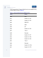
1
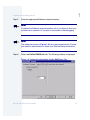
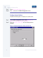
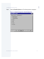
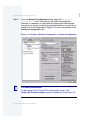
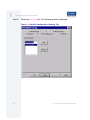
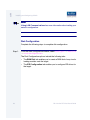
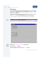
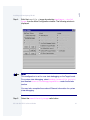
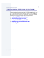
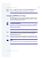
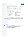
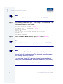
OS-9® for RPX Lite Board
Guide
Version 4.7
w w w. r a d i s y s . c o m
Revision A • July 2006
Copyright and publication information
Reproduction notice
This manual reflects version 4.7 of Microware OS-9.
Reproduction of this document, in part or whole, by any means,
electrical, mechanical, magnetic, optical, chemical, manual, or
otherwise is prohibited, without written permission from RadiSys
Microware Communications Software Division, Inc.
The software described in this document is intended to
be used on a single computer system. RadiSys
Corporation expressly prohibits any reproduction of the
software on tape, disk, or any other medium except for
backup purposes. Distribution of this software, in part
or whole, to any other party or on any other system
may constitute copyright infringements and
misappropriation of trade secrets and confidential
processes which are the property of RadiSys
Corporation and/or other parties. Unauthorized
distribution of software may cause damages far in
excess of the value of the copies involved.
Disclaimer
The information contained herein is believed to be accurate as of
the date of publication. However, RadiSys Corporation will not be
liable for any damages including indirect or consequential, from
use of the OS-9 operating system, Microware-provided software,
or reliance on the accuracy of this documentation. The
information contained herein is subject to change without notice.
July 2006
Copyright ©2006 by RadiSys Corporation
All rights reserved.
EPC and RadiSys are registered trademarks of RadiSys Corporation. ASM, Brahma, DAI, DAQ, MultiPro, SAIB, Spirit, and ValuePro are
trademarks of RadiSys Corporation.
DAVID, MAUI, OS-9, OS-9000, and SoftStax are registered trademarks of RadiSys Corporation. FasTrak, Hawk, and UpLink are
trademarks of RadiSys Corporation.
†
All other trademarks, registered trademarks, service marks, and trade names are the property of their respective owners.
Ta bl e o f C on t e n ts
Chapter 1: Installing and Configuring OS-9®
6
7
7
7
8
9
10
13
13
13
14
16
17
17
20
22
28
30
33
34
35
37
39
41
42
42
5
Development Environment Overview
Requirements and Compatibility
Host Hardware Requirements (PC Compatible)
Host Software Requirements (PC Compatible)
Target Hardware Requirements
Target Hardware Setup
Connecting the Target to the Host
Building the OS-9 ROM Image
Coreboot
Bootfile
Starting the Configuration Wizard
Creating and Configuring the ROM Image
Select System Type
Configure Coreboot Options
Configure System Options
Network Configuration
Disk Configuration
Build Image
Transferring the ROM Image to the Target
Configuring TFTPServer32 on the Host
Configuring EEPROM on the Target
Loading the OS-9 ROM Image into RAM
Programing the OS-9 ROM Image into Flash
Autobooting OS-9
Optional Procedures
Preliminary Testing
OS-9 for the RPX Lite Board Guide
3
Chapter 2: Board Specific Reference
46
48
48
48
52
53
Boot Menu Options
Runtime Information and Configuration Options
Sample Bootfile Images
OS-9 Vector Mapping
Dual-port RAM Mapping
Flash Memory Usage
Appendix A: Board Specific Modules
56
56
56
56
56
57
57
58
58
58
58
59
60
4
45
55
Low-Level System Modules
System Modules
Configuration Modules
Debugging Modules
Timer Modules
Console Drivers
Ethernet Driver
High-Level System Modules
Real Time Clock Driver
Ticker
Shared Libraries
Serial and Console Drivers
Common System Modules List
OS-9 for the RPX Lite Board Guide
C h a p t e r 1 : I n s ta l l i n g a n d C o n f i g u r i n g
O S- 9 ®
This chapter describes installing and configuring OS-9® on the RPX
Lite target board. It includes the following sections:
More In
fo More
Informatio
n More Inf
ormation M
ore Inform
ation More
-6-
•
Development Environment Overview
•
Requirements and Compatibility
•
Target Hardware Setup
•
Connecting the Target to the Host
•
Building the OS-9 ROM Image
•
Transferring the ROM Image to the Target
•
Optional Procedures
For More Information
You can find hardware documentation at the following URL:
http://www.embeddedplanet.com/documentation_and_manuals.htm#RPX Lite (RPXL)
5
1
Installing and Configuring OS-9®
Development Environment Overview
Fig. 1-1 shows a typical development environment for the RPX Lite
board. The components shown include the minimum required to enable
OS-9 to run on the board.
Figure 1-1 RPX Development Environment
Power Supply
Ethernet
Target System
6
Serial Connection
Host Development System
OS-9 for the RPX Lite Board Guide
1
Installing and Configuring OS-9®
Requirements and Compatibility
Host Hardware Requirements (PC Compatible)
Your host PC must meet the following minimum requirements:
•
Windows 95, 98, ME, 2000, or NT
•
300-400 MB of free disk space
•
an additional 235MB of free disk space is required to run
PersonalJava™ for OS-9
•
the RPX Lite Board Level Support package requires about 100
MB of free disk space
•
16MB of RAM (64MB recommended)
•
Serial port
Host Software Requirements (PC Compatible)
Your host PC must have the following applications:
•
Microware OS-9 for PowerPC
•
A terminal emulation program (such as Hyperterminal that
comes with Microsoft Windows 95, Windows 98, and Windows NT
4.0).
OS-9 for the RPX Lite Board Guide
7
1
Installing and Configuring OS-9®
Target Hardware Requirements
Your target system requires the following hardware:
8
•
Power supply
•
Ethernet 10BaseT and connecting cables
•
RS-232 serial connectors and cables
•
minimum of 4MB DRAM/2MB Flash
OS-9 for the RPX Lite Board Guide
1
Installing and Configuring OS-9®
Target Hardware Setup
This section describes any switch settings that must be made on the
target board. Figure 1-2 shows a properly configured RPX Lite target
board.
Figure 1-2 Target Board Switch Settings
Set DIP
switches as
shown. For
autobooting
the OS-9
ROM image,
DIP switches
3 and 4 are
set to Off.
ON
1
JP1
Set jumper JP4
as shown
OS-9 for the RPX Lite Board Guide
2
3
4
JP4
Network/Serial
Connection
Power Supply
9
1
Installing and Configuring OS-9®
Connecting the Target to the Host
This section describes connecting the target board to the Host PC via
serial and Ethernet connections. It also describes using a terminal
emulation program for the target.
Note
Your development system must have the following basic elements to
complete this procedure:
• serial connection between the Host PC and the Target
• Ethernet connection from your Host and Target to a network
• terminal emulation program (for example Hyperterminal)
• appropriate power supply to the Target
Complete the following steps to connect the target to the host:
Step 1.
Connect the target’s RS-232 COM port to an unused RS-232 COM port
on your Host PC using a serial cable.
Note
The RS232 COM port is marked MON on the RPX Lite board.
Step 2.
Connect the target board to an Ethernet network. Your Host PC must
also be connected to a network. You will use TFTP later in this
procedure to move the ROM image from the Host to the target.
Step 3.
Start Hyperterminal on the Host PC by selecting Start -> Programs
-> Accessories -> Hyperterminal.
10
OS-9 for the RPX Lite Board Guide
1
Installing and Configuring OS-9®
Step 4.
Enter a name for your Hyperterminal session.
Step 5.
Select an icon for the new Hyperterminal session. A new icon will be
created with the name of your session associated with it.
Step 6.
Click OK.
Step 7.
In the Connect To dialog box, go to the Connect using pull-down
menu and enter the communications port to be used to connect to the
target system.
Step 8.
Click OK.
Step 9.
Configure the Port Settings tab, as shown in Figure 1-3.
Figure 1-3 COM Port Settings
Step 10. Click OK.
OS-9 for the RPX Lite Board Guide
11
1
Installing and Configuring OS-9®
Step 11. In the Hyperterminal window, select File/Properties. Click on the
Settings tab and select the following:
Terminal Keys
Emulation = Auto Detect
Backscroll Buffer Lines = 500
Step 12. Click OK.
Step 13. Go to the Hyperterminal menu and select Call/Connect from the
pull-down menu to establish your terminal session with the Target. If
you are connected, the bottom left corner of your Hyperterminal screen
will display the word connected.
Step 14. Leave the Hyperterminal window open on your desktop (or minimized);
you will use the window again later in this procedure.
12
OS-9 for the RPX Lite Board Guide
1
Installing and Configuring OS-9®
Building the OS-9 ROM Image
The OS-9 ROM Image is a set of files and modules that collectively
make up the OS-9 operating system. The specific ROM Image contents
can vary from system to system depending on hardware capabilities
and user requirements.
To simplify the process of loading and testing OS-9, the ROM Image is
generally divided into two parts: the low-level image, called coreboot,
and the high-level image, called bootfile.
Coreboot
The coreboot image is generally responsible for initializing hardware
devices and locating the high-level (or bootfile) image as specified by its
configuration. For example from a FLASH part, a harddisk, or Ethernet.
It is also responsible for building basic structures based on the image it
finds and passing control to the kernel to bring up the OS-9 system.
Bootfile
The bootfile image contains the kernel and other high-level modules
(initialization module, file managers, drivers, descriptors, applications).
The image is loaded into memory based on the device you select from
the boot menu. The bootfile image normally brings up an OS-9 shell
prompt, but can be configured to automatically start an application.
Microware provides a Configuration Wizard to create a coreboot image,
a bootfile image, or an entire OS-9 ROM Image. The wizard can also be
used to modify an existing image. The Configuration Wizard is
automatically installed on your host PC during the OS-9 installation
process.
OS-9 for the RPX Lite Board Guide
13
1
Installing and Configuring OS-9®
Starting the Configuration Wizard
The Configuration Wizard is the application used to build the coreboot,
bootfile, or ROM image. To start the Configuration Wizard, perform the
following steps:
Step 1.
From the Windows desktop, select Start -> RadiSys ->
Microware OS-9 for <product> -> Configuration Wizard.
You should see the following opening screen:
Figure 1-4 Configuration Wizard Opening Screen
Step 2.
14
Select your target board from the Select a board pull-down menu.
OS-9 for the RPX Lite Board Guide
1
Installing and Configuring OS-9®
Step 3.
Select the Create new configuration radio button from the
Select a configuration menu and type in the name you want to give
your ROM image in the supplied text box. This names your new
configuration, which can later be accessed by selecting the Use
existing configuration pull down menu.
Step 4.
Select the Advanced Mode radio button from the Choose Wizard
Mode field and click OK. The Wizard’s main window is displayed. This is
the dialog from which you will proceed to build your image. An example
is shown in Figure 1-5.
Figure 1-5 Configuration Wizard Main Window
OS-9 for the RPX Lite Board Guide
15
1
Installing and Configuring OS-9®
Creating and Configuring the ROM Image
This section describes how to use the Configuration Wizard to create
and configure your OS-9 ROM image.
Note
The OS-9 ROM image comprises two files--coreboot.s and
bootfile.s. For the RPX Lite target board, these two files are built
and transferred from the host PC to the target board separately.
Note
This section provides an example of an OS-9 ROM image successfully
built on a host PC and transferred to an RPX Lite target board. You may
have to modify your selections depending on your application.
16
OS-9 for the RPX Lite Board Guide
1
Installing and Configuring OS-9®
Select System Type
Configure system type options by selecting Configure -> Sys ->
Select System Type from the Main Configuration window. Figure 1-6
shows the proper settings.
Figure 1-6 System Type Settings
Configure Coreboot Options
To configure your coreboot options, complete the following steps:
Step 1.
From the Main Configuration window, select Configure -> Coreboot
-> Main configuration.
Step 2.
Select the Debugger tab.
OS-9 for the RPX Lite Board Guide
17
1
Installing and Configuring OS-9®
Step 3.
Under Select Debugger, select RomBug. This sets Ethernet as the
method for user state debugging. Select None if you do not want to
debug your program.
Note
To perform system state debugging, select Ethernet under Remote
Debug Connection. If you set Ethernet as the method for system state
debugging, you will not be able to perform user state debugging via
Ethernet.
For system state debugging, you must also set the parameters in the
Ethernet tab of the coreboot configuration.
Step 4.
Select the Ethernet tab. The following window is displayed.
Figure 1-7 Coreboot Configuration—Ethernet Tab
18
OS-9 for the RPX Lite Board Guide
1
Installing and Configuring OS-9®
Step 5.
Enter the appropriate Ethernet setup information.
Note
Complete the Ethernet setup information only if you intend to boot your
system over a network or if you plan to use system state debugging.
Note
The addresses shown in Figure 1-8 are for demonstration only. Contact
your network administrator to obtain your Ethernet Setup information.
Step 6.
Select the Define ROM Ports tab. The following window is displayed.
Figure 1-8 Coreboot Configuration—Define ROM Ports Tab
OS-9 for the RPX Lite Board Guide
19
1
Installing and Configuring OS-9®
Step 7.
Select Define Other Boot Options.
Step 8.
Click OK and return to the Main Configuration window.
Configure System Options
Complete the following steps to configure your system options:
Step 1.
From the Main Configuration window, select Configure ->
Bootfile -> Configure System Options.
Step 2.
Select the Define /term Port tab. The following window is
displayed.
Figure 1-9 Bootfile Configuration—Define /term Port Tab
20
OS-9 for the RPX Lite Board Guide
1
Installing and Configuring OS-9®
Step 3.
Select the Bootfile Options tab. The following window is displayed.
Figure 1-10 Bootfile Configuration—Bootfile Options Tab
OS-9 for the RPX Lite Board Guide
21
1
Installing and Configuring OS-9®
Network Configuration
To use the target board across a network--once the target is
booted--complete the following steps:
Step 1.
22
If you want to use the target board across a network, you will need to
configure the Ethernet settings within the Configuration Wizard. To do
this, select Configure -> Bootfile -> Network
Configuration from the Wizard’s main menu.
OS-9 for the RPX Lite Board Guide
1
Installing and Configuring OS-9®
Step 2.
From the Network Configuration dialog, select the Interface
Configuration tab. From here you can select and enable the
interface. For example, you can select the appropriate Ethernet card
from the list of options on the left and specify whether you would like to
enable IPv4 or IPv6 addressing. Figure 1-11 shows an example of the
Interface Configuration tab.
Figure 1-11 Bootfile -> Network Configuration -> Interface Configuration
More In
fo More
Informatio
n More Inf
ormation M
ore Inform
ation More
-6-
For More Information
To learn more about IPv4 and IPv6 functionalities, refer to the
Using LAN Communications manual, included with this product CD.
OS-9 for the RPX Lite Board Guide
23
1
Installing and Configuring OS-9®
More In
fo More
Informatio
n More Inf
ormation M
ore Inform
ation More
-6-
Step 3.
24
For More Information
Contact your system administrator if you do not know the network
values for your board.
Once you have made your settings in the Network Configuration
dialog, click OK.
OS-9 for the RPX Lite Board Guide
1
Installing and Configuring OS-9®
Step 4.
Select the DNS Configuration tab. The following window is
displayed:
Figure 1-12 Bootfile Configuration--DNS Configuration Tab
OS-9 for the RPX Lite Board Guide
25
1
Installing and Configuring OS-9®
Step 5.
Select the Gateway tab. The following window is displayed:
Figure 1-13 Bootfile Configuration--Gateway Tab
26
OS-9 for the RPX Lite Board Guide
1
Installing and Configuring OS-9®
Step 6.
Select the SoftStax® Setup tab. The following window is displayed:
Figure 1-14 Bootfile Configuration--SoftStax Setup Tab
Note
This configuration is set for user state debugging on the target board.
For system state debugging, select Disable SoftStax.
Step 7.
Select the SoftStax Options tab.
OS-9 for the RPX Lite Board Guide
27
1
Installing and Configuring OS-9®
Note
Using LAN Communications has more information about setting your
network configuration.
Disk Configuration
Complete the following steps to complete disk configuration:
Step 1.
From the main configuration window, select Configure -> Bootfile
-> Disk Configuration.
The Disk Configuration options include the following tabs:
28
•
The RAM Disk tab enables you to create a RAM disk of any size for
loading modules onto the target.
•
The IDE Configuration tab enables you to configure IDE drives for
the target.
OS-9 for the RPX Lite Board Guide
1
Installing and Configuring OS-9®
Step 2.
Select the Init Options tab. The following window is displayed.
Figure 1-15 Bootfile Configuration—Init Options Tab
Step 3.
Select the Mshell option for the initial module name. This causes
OS-9 to start a console shell usable from your terminal window. Initial
Device Name should be selected as No Disk.
The tick rate is 100 and ticks per timeslice is set to 2. If you look at the
Parameter List box, you see the commands that OS-9 executes upon
system start-up.
Step 4.
Click OK to return to the Main Configuration window.
OS-9 for the RPX Lite Board Guide
29
1
Installing and Configuring OS-9®
Build Image
For the RPX Lite target board, the Build Image section of the Wizard
requires two separate operations for building the coreboot.s and
bootfile.s images.
The build process creates and stores two files—coreboot.s and
bootfile.s—in the following directory on your host system:
/mwos/OS9000/821/PORTS/RPXL850SR/BOOTS/INSTALL/PORTBOOT/
Step 1.
Build the coreboot image by selecting Configure -> Build Image
from the Main Configuration window. The following window is displayed.
Step 2.
Select the Coreboot Only Image radio button.
Step 3.
Click on the Build button.
After the image is built, click on the Finish button.
30
OS-9 for the RPX Lite Board Guide
1
Installing and Configuring OS-9®
Step 4.
Build the bootfile.s image by selecting Configure -> Build
Image from the Main Configuration window. The following window is
displayed.
Note
This configuration is set for user state debugging on the Target board.
For system state debugging, select ROMBug in Bootfile (p2init)
and deselect User State Debugging Modules under the Include
section.
You must also complete the coreboot Ethernet information for system
state debugging.
Step 5.
Select the Bootfile Only Image radio button.
OS-9 for the RPX Lite Board Guide
31
1
Installing and Configuring OS-9®
Step 6.
Click on the Build button.
After the image is built, click on the Finish button.
Note
After the coreboot.s and bootfile.s images are built and you are
returned to the Main Configuration window, you can select File ->
Save Settings before exiting the Wizard. This saves the settings for
your particular configuration.
32
OS-9 for the RPX Lite Board Guide
1
Installing and Configuring OS-9®
Transferring the ROM Image to the Target
This section describes how to load the OS-9 ROM image from the Host
PC to the Target board’s RAM. From there, the OS-9 ROM image can
be moved into Flash and set up for autobooting. Transferring the ROM
image to the Target board includes the following basic tasks:
•
Configuring TFTPServer32 on the Host
•
Configuring EEPROM on the Target
•
Loading the OS-9 ROM Image into RAM
•
Programing the OS-9 ROM Image into Flash
•
Autobooting OS-9
OS-9 for the RPX Lite Board Guide
33
1
Installing and Configuring OS-9®
Configuring TFTPServer32 on the Host
TFTPServer32 is the Trivial File Transfer Protocol (TFTP) server utility
that must be installed on your host PC during installation. This software
tool must be configured properly on the Host in order to transfer the
ROM image to the target.
Step 1.
On the Host PC, start TFTPServer32, by clicking the Start button on
the Windows desktop.
Step 2.
Select Programs --> TFTPServer --> TFTPServer32.
Step 3.
In the TFTP application, go to the menu and select System --> Setup
and click the Outbound tab. The path to where the ROM image is
located must be shown in the Outbound File Path box.
Figure 1-16 TFTP Server Options Window
The Outbound file path is:
/mwos/OS9000/821/PORTS/RPXL850SR/BOOTS/INSTALL/PORTBOOT/
TFTPServer finds the ROM image in this directory and downloads it to
the target machine.
All other tab options use the default settings.
34
OS-9 for the RPX Lite Board Guide
1
Installing and Configuring OS-9®
Step 4.
Click OK to apply the changes and exit the Server Options window.
Step 5.
Leave TFTPServer32 running (or minimized) on your desktop.
Configuring EEPROM on the Target
EEPROM is part of the utility software provided on the RPX Lite target
board. EEPROM must be configured properly on the target in order to
transfer the ROM image from the host.
More In
fo More
Informatio
n More Inf
ormation M
ore Inform
ation More
-6-
For More Information
This process uses the resident software on the target from Embedded
Planet. For more information about the resident software, refer to the
RPX Lite User’s Manual.
Step 1.
Confirm that the reference board is connected to your host PC via the
serial and Ethernet connections described in the Connecting the
Target to the Host section.
Step 2.
Reboot the target board by disconnecting and reconnecting the power
supply. The following text should appear in your Hyperterminal window.
Note
This is the window on your Host PC desktop described on the page 12.
OS-9 for the RPX Lite Board Guide
35
1
Installing and Configuring OS-9®
DRAM1:wwwwwvvvvvCCCCCVVVVV CaV NVRAM: CaV
-------------------------------------------------RPX utility program, Copyright (C) 1998-1999, RPCg LLC, All Rights Reserved.
Reset(0100): ExHard ExSoft ChkStop, TESR:0000 Core.Pv/Cp=2100.0050/0065
BCSR : OK
RTC : OK, battery LOW or absent, tics/sec=1, time = 3 sec
SPI : OK, I2C: OK, STTM: OK, 29.5c, EEcfg: OK, 256b, cs:2301
ENET : [zero], 0010EC000CD1, INET: AC10012C
FLASH: OK, 8 Mb(32x8), id=01:49, cs:274E es:274E OK (FFF00000:FFF3C528)
NVRAM: OK, 0 Kb, NVR battery GOOD
DRAM : OK, 16 Mb, 10 columns
===> RPX Main
RPX-Lite BW 850SR 50Mhz/8Mhz Ic ~Dc RPXU v1.40
1 test BCSR
A Add-on board tests
2 test dip switches
B rpxBug command line (ctrl-B)
3 test LEDs
C Configure EEPROM
4 test SPI I2C STTM EEPR,CFG
L Load RAM
5 test FLASH firmware chksum
O On-board I/O tests
6 test NVRAM/SRAM
P Program FLASH
7 test DRAM (destructive)
R hard Reset
8
S Scan FLASH for executables
9 run all tests
T display Time & Temperature
RPX Main menu: press 123456789 or ABCLOPRST key : <?> :
Step 3.
Enter C (Configure EEPROM) in the RPX Main menu in your
Hyperterminal window. This takes you to the RPX Configure menu.
Step 4.
Enter 7 (Modify parameters of system configuration keys) in the RPX
Configure menu.
Step 5.
Change the following values in the Configure EEPROM dialog:
•
IP address (IP address of the target board)
•
AutoBoot name (must be set to @FFF80EE1)
•
TFTP IP address (IP address of the Host PC)
Note
The IP address and TFTP IP address must be typed in hexadecimal
format. For example, 172.16.4.163 becomes AC1004A3.
172 = AC; 16 = 10; 4 = 04; 163 = A3
36
OS-9 for the RPX Lite Board Guide
1
Installing and Configuring OS-9®
Note
For the values not being changed in the Configure EEPROM dialog,
press <ENTER> to proceed to the next field.
Step 6.
Return to the RPX Configure menu and select 9 (Write parameters to
EEPROM). When prompted, type YES.
Step 7.
Return to the RPX Configure menu by pressing <ENTER>.
Step 8.
Return to the RPX Main menu by pressing <Esc> and typing YES to
reset the target.
Loading the OS-9 ROM Image into RAM
Load the OS-9 ROM image via TFTP Boot into RAM. The RPX Lite
utility software has TFTP software that loads a specified S-Record into
RAM. To load the ROM image, complete the following steps:
Step 1.
From the RPX Main menu, type L (Load RAM) and then type 7 (Load
using TFTP via Ethernet). The following will display on your screen:
Load using tftp via Ethernet
Enter server IP address <AC1004A3> : <ENTER>
Enter server filename
<coreboot.s> : coreboot.s
Enter address offset : <00000000 hex> : 0
Starting tftp download:
inetARP(): OK
.1.2.4.8.16.32.64.128.256.512.1024.2048.4096
load_tftp(): OK
503852 data bytes, 6299 S-records, 985 tftp blocks, 0 repeated blocks
start address = 00000000
Step 2.
Return to the RPX Load menu.
OS-9 for the RPX Lite Board Guide
37
1
Installing and Configuring OS-9®
Note
The coreboot file is loaded into memory address 0x00100000
Step 3.
From the RPX Load menu, type 7 (Load using TFTP via Ethernet). The
following will display on your screen:
Enter server IP address <AC1004A3> : <ENTER>
Enter server filename
<coreboot.s> : bootfile.s
Enter address offset : <00000000 hex> : <ENTER>
Starting tftp download:
inetARP(): OK
.1.2.4.8.16.32.64.128.256.512.1024.2048.4096.8192.16384.32768
load_tftp(): OK
2847900 data bytes, 35600 S-records, 5563 tftp blocks, 0 repeated blocks
start address = 00000000
Step 4.
Return to the RPX Main menu by typing <Esc> and <Enter>.
Note
The bootfile is loaded into memory starting at address 0x00200000.
Note
You may receive “Timed Out” error messages in the Hyperterminal
window during the loading process. This is usually caused by network
traffic on large and busy networks.
If you receive a “Timed Out” message, connect the host and target
directly with your Ethernet cable, bypassing the network. After making
these connections, try the loading process again.
38
OS-9 for the RPX Lite Board Guide
1
Installing and Configuring OS-9®
Programing the OS-9 ROM Image into Flash
Programming the RPX Lite Flash memory includes erasing specific
regions of Flash and loading files from RAM into Flash. Complete the
following steps to program the RPX Lite Flash.
Step 1.
Type P (Program Flash) from the RPX Main menu.
Step 2.
Type 2 (Erase section) from the RPX Flash menu. Enter the following
addresses—one at a time—into the dialog. You are required to type
<ENTER> and YES to confirm each operation.
!
•
FFF80000—area for coreboot
•
FFC00000—area for bootfile
•
FFC40000—area for bootfile
•
FFC80000—area for bootfile
•
FFCC0000—area for bootfile
•
FFD00000—area for bootfile
WARNING
Do not erase ALL regions of Flash memory. Do not erase section
fff00000 of Flash Memory. Either or both of these operations will erase
the RPX Lite utility software.
Note
You may need to erase more sections from Flash and increase the
number of bytes to program if your bootfile exceeds 1 MB. The correct
size of bootfile can be obtained by looking at the size of
/mwos/OS9000/821/PORTS/RPXL850SR/BOOTS/INSTALL/PORTBOOT/bootfile.
OS-9 for the RPX Lite Board Guide
39
1
Installing and Configuring OS-9®
Step 3.
Return to the RPX Flash menu.
Step 4.
Program coreboot into Flash by typing 9 (Program from Buffer) and
entering the following into the dialog:
program: Enter target address: <hex>: fff80000 <ENTER>
program: Enter source address: <hex>: 00100000 <ENTER>
program: Enter number of bytes: <hex>: 00040000 <ENTER>
Step 5.
Program bootfile into Flash by typing 9 (Program from Buffer) and
entering the following into the dialog:
program: Enter target address: <hex>: ffc00000 <ENTER>
program: Enter source address: <hex>: 00200000 <ENTER>
program: Enter number of bytes: <hex>: 00140000 <ENTER>
Step 6.
Return to the RPX Main menu by typing <Esc> and <ENTER>.
Step 7.
Scan for Flash Executables by selecting S from the RPX Main menu.
The following should appear on your screen:
Scanning for program signatures: ...............OK
01:[@FFF31278] RPXsignature=1.0 NAME=RPXBOOT START=FFF00100 Version=1.40
02:[@FFF80EE1] RPXsignature=1.0 NAME=OS9BOOT START=FFF80000
===> Select an item : <none> :
When prompted, type 2 <ENTER> and type YES. OS-9 will boot on the
target.
40
OS-9 for the RPX Lite Board Guide
1
Installing and Configuring OS-9®
Autobooting OS-9
You can configure your target system to autoboot OS-9 upon startup by
completing the following steps.
Step 1.
Remove power to the board.
Step 2.
Set dip switches 3 and 4 to off.
Step 3.
Restore power to the board. Your screen will display the following:
DRAM1:wwwwwvvvvvCCCCCVVVVV CaV NVRAM: CaV
-------------------------------------------------RPX utility program, Copyright (C) 1998-1999, RPCg LLC, All Rights Reserved.
Autoboot: @FFF80EE1 @FFF80EE1 points to a signature
Autoboot: executing...
SigExec(): start addr = FFF80000
SigExec(): transferring control to program
OS-9000 Bootstrap for the PowerPC(tm)
Now trying to Override autobooters.
Now trying to Copy embedded OS-9000 to RAM and boot.
Now searching memory ($ffc00000 - $ffefffff) for an OS-9000 Kernel...
An OS-9000 kernel was found at $ffc00000
A valid OS-9000 bootfile was found.
$
OS-9 for the RPX Lite Board Guide
41
1
Installing and Configuring OS-9®
Optional Procedures
The following section provides optional procedures you can perform
after installing and configuring OS-9 on your board.
Preliminary Testing
Once you have established an OS-9 prompt on your target system, you
can perform the following procedures to test your system:
Step 1.
Type mdir at the prompt.
mdir displays all the modules in memory. You may have to hit the
space bar to scroll the output.
Step 2.
Type procs at the prompt.
procs displays the processes currently running in the system.
Step 3.
Test the networking on your system.
Select a host on the Ethernet network and run the ping utility. The
following display shows a successful ping to a machine called
solkanar.
$ ping solkanar
PING solkanar.microware.com (172.16.2.51): 56 data bytes
64 bytes from 172.16.2.51: ttl=128 time=0 ms
Step 4.
Test telnet.
Select a host machine that allows telnet access and try the OS-9
telnet utility. The following display shows a successful telnet to a
machine called delta.
$ telnet delta
Trying 172.16.1.40...Connected to delta.microware.com.
Escape character is '^]'.
capture closed.
OS-9/68K V3.0.3 Delta VME177 - 68060 98/12/24 14:41:51
User name?: curt
42
OS-9 for the RPX Lite Board Guide
1
Installing and Configuring OS-9®
Password:
Process #101 logged on 98/12/24 14:41:56
Welcome!
***********************************************************
*
WELCOME TO DELTA - THE :OS-9 68K: MACHINE *
Step 5.
Test telnet from your host PC to the reference board.
From the Windows Start menu, select Run and type telnet
<hostname> and click OK. A telnet window should display with a $
prompt. Type mdir from the prompt. You should see the same module
listing as on the serial console port.
You have now created your OS-9 ROM image, loaded the ROM image
to the target, and established network connectivity with the target.
OS-9 for the RPX Lite Board Guide
43
1
Installing and Configuring OS-9®
44
OS-9 for the RPX Lite Board Guide
C h a p t e r 2 : B o a rd Sp e c if i c R e f e r e n c e
This chapter contains information that is specific to the RPX Lite
reference board from Embedded Planet. It contains the following
sections:
•
Boot Menu Options
•
Runtime Information and Configuration Options
Note
This document describes using the RPX Lite with the Motorola
MPC850SR processor.
More In
fo More
Informatio
n More Inf
ormation M
ore Inform
ation More
-6-
For More Information
For general information on porting OS-9, see the OS-9 Porting Guide.
45
2
Board Specific Reference
Boot Menu Options
You select your boot device menu options using the configuration
wizard. For each boot device option, you can select whether you want it
to be displayed on a boot menu, set up to autoboot, or both. The
autoboot option enables the device selected to automatically boot up
the high-level bootfile, bypassing the boot device menu.
Note
When using the configuration wizard, you should select only one device
for autoboot on your system.
Following is an example of the Boot Menu displayed in the terminal
emulation window (using Hyperterminal):
OS-9000 Bootstrap for the PowerPC(tm)
Now trying to Override autobooters.
BOOTING PROCEDURES AVAILABLE ----- <INPUT>
Scan SCSI devices ---------------Boot FDC floppy -----------------Boot from PC-Floppy -------------Boot from Teac SCSI floppy drive Boot from SCSI PC-Floppy --------Boot from Viper tape drive ------Boot over Ethernet --------------Boot from SCSI(SCCS) hard drive -Boot embedded OS-9000 in-place --Enter system debugger -----------Restart the System ---------------
<ioi>
<fd>
<pf>
<fs>
<pfs>
<vs>
<eb>
<hs>
<bo>
<break>
<q>
Select a boot method from the above menu:
46
OS-9 for the RPX Lite Board Guide
2
Board Specific Reference
What you select for boot options in the configuration wizard determines
what modules are included in the coreboot image. Table 2-1 lists some
of the supported boot devices for OS-9:
Table 2-1 Supported Boot Methods
Type of Boot
Description
Boot from RBF hard disk
Boot from a standard SCSI hard
disk (hs).
Floppy Disk
Boot from floppy disk. You must
select if the floppy is controlled by
a Random Block File System
(RBF) (fd or fs) or PC File
System (pf or pfs).
Boot embedded OS-9
in-place
Boot OS-9 from FLASH (bo).
Copy embedded OS-9 to
RAM and Boot
Copy OS-9 from FLASH (if stored
there) to RAM and boot (lr).
Boot using bootp over
Ethernet
OS-9 is downloaded via TFTP from
a server system.
OS-9 for the RPX Lite Board Guide
47
2
Board Specific Reference
Runtime Information and Configuration
Options
Sample Bootfile Images
The sample bootfile images provided in this package offer a variety of
configurations for high-level OS-9 bootfiles on the RPX Lite target
platform from Embedded Planet.
Sample bootfile images are located in the following directory:
<MWOS>/OS9000/821/PORTS/RPX850SR/BOOTS/SYSTEMS/PORTBOOT
OS-9 Vector Mapping
This section contains the vector mappings and dual-port RAM
mappings for the MPC850SR processor.
The system modules siuirq and cpicirq map interrupts coming
from the SIU and CPM into the OS-9 vector table according to the
following mappings.
SIU (System Interface Unit) vectors are mapped starting at vector 0x40
as shown in Table 2-2.
Table 2-2 System Interface Unit Vectors
48
Vector
Source
0x40
IRQ0
0x41
Level 0
0x42
IRQ1
0x43
Level 1
OS-9 for the RPX Lite Board Guide
2
Board Specific Reference
Table 2-2 System Interface Unit Vectors (continued)
Vector
Source
0x44
IRQ2
0x45
Level 2
0x46
IRQ3
0x47
Level 3
0x48
IRQ4
0x49
Level 4 (CPIC)
0x4a
IRQ5
0x4b
Level 5
0x4c
IRQ6
0x4d
Level 6
0x4e
IRQ7
0x4f
Level 7
OS-9 for the RPX Lite Board Guide
49
2
Board Specific Reference
CPM (Communications Processor Module) vectors are mapped starting
at vector 0x50 as shown in Table 2-3.
Table 2-3 Communications Processor Module Vectors
50
Vector
Source
0x50
Error
0x51
Parallel I/O—PC4
0x52
Parallel I/O—PC5
0x53
SMC2/PIP
0x54
SMC1
0x55
SPI
0x56
Parallel I/O—PC6
0x57
Timer 4
0x58
Reserved
0x59
Parallel I/O—PC7
0x5a
Parallel I/O—PC8
0x5b
Parallel I/O—PC9
0x5c
Timer 3
0x5d
Reserved
0x5e
Parallel I/O—PC10
0x5f
Parallel I/O—PC11
OS-9 for the RPX Lite Board Guide
2
Board Specific Reference
Table 2-3 Communications Processor Module Vectors (continued)
Vector
Source
0x60
I2C
0x61
RISC Timer Table
0x62
Timer 2
0x63
Reserved
0x64
IDMA2
0x65
IDMA1
0x66
SDMA Channel Bus Error
0x67
Parallel I/O—PC12
0x68
Parallel I/O—PC13
0x69
Timer 1
0x6a
Parallel I/O—PC14
0x6b
SCC4
0x6c
SCC3
0x6d
SCC2
0x6e
SCC1
0x6f
Parallel I/O—PC15
OS-9 for the RPX Lite Board Guide
51
2
Board Specific Reference
Dual-port RAM Mapping
The MPC850SR processor includes 5120 bytes of dual-port RAM for
buffer descriptor and microcode use. Since the high- and low-level
drivers both use this area, its usage must be coordinated. Table 2-4
lists reserved locations and their uses.
Table 2-4 Dual Port RAM Use Map
52
Offset into DPRAM
Use
0x0 - 0x0f
SCC1
0x10 - 0x1f
SCC2
0x20 - 0x2f
SCC3
0x30 - 0x3f
SCC4
0x40 - 0x4f
SMC1
0x50 - 0x5f
SMC2
0x60 - 0xff
reserved
0x100 - 0x17f
Ethernet
0x180 - 0x200
reserved
OS-9 for the RPX Lite Board Guide
2
Board Specific Reference
Flash Memory Usage
Figure 2-1 describes the various locations and contents of Flash
memory on the RPX Lite target system running OS-9.
Figure 2-1 Flash Memory Usage
FFF80000-FFFFFFFF
OS-9 core boot
FFF00000-FFF7FFFF
BSP - RPX Utility Code
OS-9 bootfile
FFC00000-
More In
fo More
Informatio
n More Inf
ormation M
ore Inform
ation More
-6-
For More Information
Refer to the RPX Lite Programmer’s Manual for a complete
description of Flash memory in the RPX Lite target system.
OS-9 for the RPX Lite Board Guide
53
2
Board Specific Reference
54
OS-9 for the RPX Lite Board Guide
A p p e n d i x A : B o a rd Spe c i f i c M o d u l e s
This appendix contains lists of high and low-level modules. The
following sections are included:
•
Low-Level System Modules
•
High-Level System Modules
•
Common System Modules List
55
A
Board Specific Modules
Low-Level System Modules
The following low-level system modules are tailored specifically for the
RPX Lite target platform. These modules can be found in the following
directory:
MWOS/OS9000/821/PORTS/RPXL850SR/CMDS/BOOTOBJS/ROM
System Modules
portmenu
retrieves a list of configured booter
names from the ROM cnfgdata
module.
romcore
provides bootstrap code.
Configuration Modules
cnfgdata
provides low-level configuration data
including configuration of a serial
console.
cnfgfunc
retrieves configuration parameters from
the cnfgdata module.
conscnfg
retrieves the name of the low-level
console driver from the cnfgdata
module.
Debugging Modules
usedebug
is a debugger configuration module.
Timer Modules
tbtimer
56
provides polling timer services using the
tblo and tbhi registers in the
MPC850SR processor.
OS-9 for the RPX Lite Board Guide
A
Board Specific Modules
Console Drivers
iosmc
provides console services for the SMC
UART on the MPC850SR.
Ethernet Driver
llquicc
OS-9 for the RPX Lite Board Guide
provides network driver services for the
MPC850SR Ethernet port.
57
A
Board Specific Modules
High-Level System Modules
The following OS-9 system modules are tailored specifically for the
MPX Lite target platform from Embedded Planet. Unless otherwise
specified, each module can be found in a file of the same name in the
following directory:
<MWOS>/OS9000/821/PORTS/RPXL850SR/CMDS/BOOTOBJS
Real Time Clock Driver
rtc821
provides OS-9 access to the real time
clock. In this release, rtc821 is the
name of the ticker regardless of the CPU
in use on your platform.
Ticker
tk821pit
provides the system ticker based on the
SIU periodic interrupt timer.
tkcpm
provides the system ticker based on the
CPM general purpose timer.
tkdec
provides the system ticker based on the
PowerPC decrementer.
Shared Libraries
picsub
58
provides interrupt enable and disable
routines to handle platform specific
interrupt controller issues for device
drivers. This module is called by all
drivers, and should be included in your
bootfile.
OS-9 for the RPX Lite Board Guide
A
Board Specific Modules
Serial and Console Drivers
sccpm
provides support for the CPM SMC and
SCC UARTS serial port.
The descriptors provided for this driver
are named t0 and term_t0, and are
located in the following directory:
<MWOS>/OS9000/821/PORTS/
RPXL850SR/CMDS/BOOTOBJS/
DESC/SCCPM
OS-9 for the RPX Lite Board Guide
59
A
Board Specific Modules
Common System Modules List
The following low-level system modules provide generic services for
OS9000 modular ROM. They are located in the following directory:
MWOS/OS9000/PPC/CMDS/BOOTOBJS/ROM
Table 2-5 Common System Modules List
60
Module
Description
bootsys
provides booter services.
console
provides high-level I/O hooks into low-level
console serial driver.
dbgentry
provides hooks to low-level debugger server.
dbgserv
is a debugger server module.
excption
is a service module.
fdc765
provides PC style floppy support.
fdman
is a target-independent booter support module
providing general booting services for RBF file
systems.
flboot
is a SCSI floptical drive disk booter.
flshcach
provides the cache flushing routine.
fsboot
is a SCSI TEAC floppy disk drive booter.
hlproto
allows user-state debugging.
hsboot
is a SCSI hard disk driver booter.
OS-9 for the RPX Lite Board Guide
A
Board Specific Modules
Table 2-5 Common System Modules List (continued)
Module
Description
ide
provides target-specific standard IDE support,
including PCMCIA ATA PC cards.
iovcons
is a hardware independent virtual console driver
that provides a telnetd-like interface to the
low-level system console.
llbootp
is a target-independent BOOTP protocol booter
module.
llip
is a target-independent internet protocol module.
llkermit
is a kermit booter (serial down loader).
llslip
is a target-independent serial line internet protocol
module. This modules uses the auxiliary
communications port driver to perform serial I/O
lltcp
is a target-independent transmission control
protocol module.
lludp
is a target-independent user datagram protocol
modules.
notify
coordinates use of low-level I/O drivers in system
and user-state debugging.
override
enables overriding of the autobooter. If the space
bar is pressed within three seconds after booting
the target, a boot menu is displayed. Otherwise,
booting proceeds with the first autobooter.
parser
parses key fields from the cnfgdata module and
the user parameter fields.
OS-9 for the RPX Lite Board Guide
61
A
Board Specific Modules
Table 2-5 Common System Modules List (continued)
62
Module
Description
pcman
is a target-independent booter support module
providing general booting services for PCF file
systems (PC FAT file systems).
protoman
is a target-independent protocol module manager.
This module provides the initial communication
entry points into the protocol module stack.
restart
restarts boot process.
romboot
locates the OS-9 bootfile in ROM, FLASH,
NVRAM.
rombreak
enables break option from the boot menu.
rombug
is a debugger client module.
scsiman
is a target-independent booter support module
that provides general SCSI command protocol
services
sndp
is a target-independent system-state network
debugging protocol module. This module acts as a
debugging client on the target, invoking the
services of dbgserv to perform debug tasks.
srecord
receives a Motorola S-record format file from the
communications port and loads it into memory.
swtimer
is a software timer.
tsboot
is a SCSI TEAC tape drive booter.
type41
is a primary partition type.
OS-9 for the RPX Lite Board Guide
A
Board Specific Modules
Table 2-5 Common System Modules List (continued)
Module
Description
vcons
is the console terminal pathlist.
vsboot
is a SCSI archive viper tape drive booter.
OS-9 for the RPX Lite Board Guide
63
A
Board Specific Modules
64
OS-9 for the RPX Lite Board Guide