1
User Manual
SOM-4461
Copyright
The documentation and the software included with this product are copyrighted 2009
by Advantech Co., Ltd. All rights are reserved. Advantech Co., Ltd. reserves the right
to make improvements in the products described in this manual at any time without
notice.
No part of this manual may be reproduced, copied, translated or transmitted in any
form or by any means without the prior written permission of Advantech Co., Ltd.
Information provided in this manual is intended to be accurate and reliable. However,
Advantech Co., Ltd. assumes no responsibility for its use, nor for any infringements
of the rights of third parties, which may result from its use.
Acknowledgements
Award is a trademark of Award Software International, Inc.
VIA is a trademark of VIA Technologies, Inc.
IBM, PC/AT, PS/2 and VGA are trademarks of International Business Machines Corporation.
Intel and Pentium are trademarks of Intel Corporation.
Microsoft Windows® is a registered trademark of Microsoft Corp.
RTL is a trademark of Realtek Semi-Conductor Co., Ltd.
ESS is a trademark of ESS Technology, Inc.
UMC is a trademark of United Microelectronics Corporation.
SMI is a trademark of Silicon Motion, Inc.
Creative is a trademark of Creative Technology LTD.
CHRONTEL is a trademark of Chrontel Inc.
All other product names or trademarks are properties of their respective owners.
SOM-4461 User Manual
Part No. 2006446100
Edition 1
Printed in Taiwan
June 2009
ii
Product Warranty (2 years)
Advantech warrants to you, the original purchaser, that each of its products will be
free from defects in materials and workmanship for two years from the date of purchase.
This warranty does not apply to any products which have been repaired or altered by
persons other than repair personnel authorized by Advantech, or which have been
subject to misuse, abuse, accident or improper installation. Advantech assumes no
liability under the terms of this warranty as a consequence of such events.
Because of Advantech’s high quality-control standards and rigorous testing, most of
our customers never need to use our repair service. If an Advantech product is defective, it will be repaired or replaced at no charge during the warranty period. For outof-warranty repairs, you will be billed according to the cost of replacement materials,
service time and freight. Please consult your dealer for more details.
If you think you have a defective product, follow these steps:
1. Collect all the information about the problem encountered. (For example, CPU
speed, Advantech products used, other hardware and software used, etc.) Note
anything abnormal and list any onscreen messages you get when the problem
occurs.
2. Call your dealer and describe the problem. Please have your manual, product,
and any helpful information readily available.
3. If your product is diagnosed as defective, obtain an RMA (return merchandize
authorization) number from your dealer. This allows us to process your return
more quickly.
4. Carefully pack the defective product, a fully-completed Repair and Replacement
Order Card and a photocopy proof of purchase date (such as your sales receipt)
in a shippable container. A product returned without proof of the purchase date
is not eligible for warranty service.
5. Write the RMA number visibly on the outside of the package and ship it prepaid
to your dealer.
Declaration of Conformity
FCC Class A
Note: This equipment has been tested and found to comply with the limits for a Class
A digital device, pursuant to part 15 of the FCC Rules. These limits are designed to
provide reasonable protection against harmful interference when the equipment is
operated in a commercial environment. This equipment generates, uses, and can
radiate radio frequency energy and, if not installed and used in accordance with the
instruction manual, may cause harmful interference to radio communications. Operation of this equipment in a residential area is likely to cause harmful interference in
which case the user will be required to correct the interference at his own expense.
iii
SOM-4461 User Manual
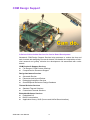
COM Design Support
A Series of Value-Added Services for Carrier Board Development
Advantech COM Design Support Services help customers to reduce the time and
work involved with designing new carrier boards. We handle the complexities of technical research and greatly minimize the development risk associated with carrier
boards.
COM Product & Support Services
! Full Range of COM Product Offerings
! Comprehensive Document Support
Design Assistance Services
! Schematic Review
! Placement and Layout Review
! Debugging Assistance Services
! General/Special Reference Design Database
Thermal Solution Services
! Standard Thermal Solutions
! Customized Thermal Solutions
Embedded Software Services
! Embedded OS
! BIOS Customization
! Application Library: SUSI (Secure and Unified Smart Interface)
SOM-4461 User Manual
iv
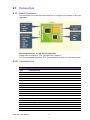
A Series of Value-Added Services for Carrier Board Development
Advantech COM Design Support Services help customers to reduce the time and
work involved with designing new carrier boards. We handle the complexities of technical research and greatly minimize the development risk associated with carrier
boards.
COM Product & Support Services
Advantech provides a full range of Computer on Modules including COM-Express,
ETX, XTX and COM-Micro to fulfill diverse customer applications. Advantech also
serves comprehensive document support to clients for project development.
Design Assistance Services
The Design Assistance Service is created to offer essential help to complete crucial
development tasks: schematic review, placement review, debugging and a general/
special database of technologies for reference purposes. All services reduce design
risks associated with completing customer carrier boards.
Thermal Solution Services
In order to provide quicker and more flexible solutions for customer's thermal
designs. Advantech provides thermal solution services including modularized thermal
solutions and customized thermal solutions.
Embedded Software Services
Advantech provides Embedded Software Services to customers who integrate
Advantech hardware products. Advantech Embedded Software Services include
Embedded BIOS services, OS services and API Library (SUSI), Embedded Software
Services help decrease design effort and project complexity, and accelerate product
development.
COM Design Support Zone: http://com.advantech.com/
Advantech reserves the right to determine, on a case by case basis, whether or not
COM Design Support Services are appropriate.
Technical Support and Assistance
For more information about this and other Advantech products, please visit our website at:
<http://www.advantech.com/>
<http://www.advantech.com/ePlatform/>
For technical support and service, please visit our support website at:
<http://support.advantech.com.tw/support/>
1. Visit the Advantech web site at www.advantech.com/support where you can find
the latest information about the product.
2. Contact your distributor, sales representative, or Advantech's customer service
center for technical support if you need additional assistance. Please have the
following information ready before you call:
– Product name and serial number
– Description of your peripheral attachments
– Description of your software (operating system, version, application software,
etc.)
– A complete description of the problem
– The exact wording of any error messages
v
SOM-4461 User Manual
Safety Instructions
1.
2.
3.
4.
5.
6.
7.
8.
9.
10.
11.
12.
13.
14.
Read these safety instructions carefully.
Keep this User Manual for later reference.
Disconnect this equipment from any AC outlet before cleaning. Use a damp
cloth. Do not use liquid or spray detergents for cleaning.
For plug-in equipment, the power outlet socket must be located near the equipment and must be easily accessible.
Keep this equipment away from humidity.
Put this equipment on a reliable surface during installation. Dropping it or letting
it fall may cause damage.
The openings on the enclosure are for air convection. Protect the equipment
from overheating. DO NOT COVER THE OPENINGS.
Make sure the voltage of the power source is correct before connecting the
equipment to the power outlet.
Position the power cord so that people cannot step on it. Do not place anything
over the power cord.
All cautions and warnings on the equipment should be noted.
If the equipment is not used for a long time, disconnect it from the power source
to avoid damage by transient overvoltage.
Never pour any liquid into an opening. This may cause fire or electrical shock.
Never open the equipment. For safety reasons, the equipment should be
opened only by qualified service personnel.
If one of the following situations arises, get the equipment checked by service
personnel:
– The power cord or plug is damaged.
– Liquid has penetrated into the equipment.
– The equipment has been exposed to moisture.
– The equipment does not work well, or you cannot get it to work according to
the user's manual.
– The equipment has been dropped and damaged.
– The equipment has obvious signs of breakage.
Safety Precaution - Static Electricity
Follow these simple precautions to protect yourself from harm and the products from
damage.
! To avoid electrical shock, always disconnect the power from your PC chassis
before you work on it. Don't touch any components on the CPU card or other
cards while the PC is on.
! Disconnect power before making any configuration changes. The sudden rush
of power as you connect a jumper or install a card may damage sensitive electronic components.
SOM-4461 User Manual
vi
Packing List
Before installation, please ensure the following items have been shipped:
! 1 SOM-4461 CPU module
! 1 Utility CD (Including manual and driver)
! 1 heatspreader 114*95*3mm
Optional Accessories
Development board
For more information please refer to "Advantech Baseboard Check List" and "Evaluation Board Reference Schematic".
You could download "Advantech Baseboard Check List" and "Evaluation Board Reference Schematic" from http://com.advantech.com/
Ordering information
Model Number Description
vii
SOM-4461 User Manual
SOM-4461 User Manual
viii
Contents
Chapter
1
General Introduction ...........................1
1.1
1.2
Introduction ............................................................................................... 2
Product Feature ........................................................................................ 3
Table 1.1: Product feature of SOM-4461..................................... 3
Mechanical Specifications......................................................................... 4
1.3.1 Dimension(mm)............................................................................. 4
1.3.2 Height on Top(mm) ....................................................................... 4
1.3.3 Height on Bottom(mm).................................................................. 4
1.3.4 Heat Spreader Dimension(mm) .................................................... 4
1.3.5 Weight(g) with Heatsink ................................................................ 4
Electrical Specifications ............................................................................ 5
1.4.1 Power supply Voltage ................................................................... 5
1.4.2 Power supply Current ................................................................... 5
Environmental Specifications .................................................................... 5
1.5.1 Operating temperature.................................................................. 5
1.5.2 Operating Humidity ....................................................................... 5
1.5.3 Storage temperature ..................................................................... 5
1.5.4 Storage Humidity .......................................................................... 5
1.3
1.4
1.5
Chapter
2
H/W installation....................................7
2.1
Connectors................................................................................................ 8
2.1.1 Board Connector........................................................................... 8
2.1.2 Connector List............................................................................... 8
Table 2.1: SDVO Connector........................................................ 8
Table 2.2: FAN1 Fan ................................................................... 9
Table 2.3: SATA connector ......................................................... 9
Mechanical .............................................................................................. 10
2.2.1 Jumper and Connector Location................................................. 10
Figure 2.1 Jumper and Connector layout (Component side)..... 10
Figure 2.2 Jumper and Connector layout (Solder side) ............. 10
2.2.2 Board Dimension ........................................................................ 11
Figure 2.3 Board Dimension layout (Component side).............. 11
Figure 2.4 Board Dimension layout (Solder side) ...................... 11
2.2.3 Heat spreader Dimension ........................................................... 12
Figure 2.5 Drawing of Heatspreader for BGA type CPU ........... 12
2.2.4 Thermal Solution......................................................................... 12
2.2
Chapter
3
BIOS settings .....................................13
3.1
3.2
BIOS Introduction.................................................................................... 14
BIOS Setup ............................................................................................. 14
3.2.1 Main Menu .................................................................................. 15
3.2.2 Standard CMOS Features .......................................................... 16
3.2.3 Advanced BIOS Features ........................................................... 17
3.2.4 Advanced Chipset Features........................................................ 19
3.2.5 Integrated Peripherals................................................................. 21
3.2.6 Power Management Setup ......................................................... 25
3.2.7 PnP/PCI Configurations .............................................................. 27
3.2.8 PC Health Status ........................................................................ 28
3.2.9 Frequency/Voltage Control ......................................................... 29
3.2.10 Load Optimized Defaults............................................................. 30
3.2.11 Set Password.............................................................................. 30
ix
SOM-4461 User Manual
3.2.12 Save & Exit Setup....................................................................... 32
3.2.13 Quit Without Saving .................................................................... 32
Chapter
4
S/W Introduction & Installation........ 33
4.1
4.2
S/W Introduction ..................................................................................... 34
Driver Installation .................................................................................... 34
4.2.1 Windows XP professional ........................................................... 34
4.2.2 Other OS..................................................................................... 34
Appendix A
Watchdog Timer................................ 35
A.1
Programming the Watchdog Timer ......................................................... 36
Appendix B
System Assignments........................ 37
B.1
System I/O Ports..................................................................................... 38
Table B.1: System I/O ports....................................................... 38
DMA Channel Assignments .................................................................... 39
Interrupt Assignments ............................................................................. 39
Table B.2: Interrupt assignments............................................... 39
1st MB Memory Map............................................................................... 40
Table B.3: 1st MB memory map ................................................ 40
B.2
B.3
B.4
SOM-4461 User Manual
x
Chapter
1
1
General Introduction
This chapter gives background
information on the SOM-4461.
Sections include:
! Introduction
! Specifications
1.1 Introduction
SOM-4461 is an embedded ETX 3.0 CPU module. The new CPU module supports
Intel N270 1.6 GHz processor with Intel 945GSE and ICH7M chipsets. SOM-4461
has an integrated graphic engine: Intel GMA950 and Microsoft DirectX 9.1. In a basic
form factor of 114 mm x 95 mm, SOM-4461 provides scalable high performance with
lower power consumption, and is an easy to integrate solution for applications utilizing a plug-in CPU module on an application-specific customer solution board.
SOM-4461 with advanced I/O capacity incorporates serial differential signaling technologies such as 36-bit LVDS, SDVO, VGA,TV out, AC97 audio, 10/100 LAN, PCI
Masters x 4, SATA x 2 ports, USB 2.0 x 4 ports, 1 EIDE, 2 serial ports, FDD/LPT port.
SOM-4461 offers design partners more choices for their own applications needing
lower power consumption while maintaining a compact form factor.
SOM-4461 complies with the "Green Function" standard and supports Idle, Standby
and Suspend modes. The small size (114 mm x 95 mm) and use of four high capacity
connectors based on the proven ETX 3.0 form factor, allows the CPU module to be
easily and securely mounted onto a customized solution board or our standard SOMDB4400/DB4700 development board.
The SOM-4461 is a highly integrated multimedia COM that combines audio, video,
and network functions. It provides dual channel 18-bit LVDS interface for small/ middle size TFT LCD displays, DDR2 memory up to 2 GB, audio interface (AC97).
SOM-4461 User Manual
2
Table 1.1: Product feature of SOM-4461
Features
Embedded Intel ATOM N270 1.6 GHz processor with low
power consumption
Chapter 1
1.2 Product Feature
Intel Atom N270+ 945GSE+ ICH7M
Intel GMA950, Microsoft DirectX* 9.1
Features
Supports multiple displays: VGA, LVDS, SDVO, TV out
Intel 10/100 Mbps LAN
Expansion: 4 PCI masters, ISA
4 x USB 2.0, 2 x SATA on board, 1 EIDE, 2 COMs, FDD/
LPT port
Specifications
Form Factor
Processor
System
Memory
Display
Ethernet
WatchDog Timer
ETX 3.0
CPU
Embedded Intel ATOM N270 1.6 GHz processor
Front Side
Bus
533 MHz FSB
System
Chipset
Intel 945GSE/ ICH7M
BIOS
AWARD 8 Mbit Flash BIOS
Technology
DDR2 400/533 MHz
Max. Capacup to 2 GB
ity
Socket
1 x 200-pin SODIMM socket
Chipset
Intel 945GSE
VRAM
DVMT 3.0 Supports up to 224 MB
Graphic
Engine
Intel GMA950, Microsoft DirectX* 9.1
LVDS
36-bit LVDS
VGA
up to 2048 x 1536
DVI
N/A
TV Out
Supports NTSC/PAL, S-Video and Composite Output interfaces
SDVO
1 SDVO Port
Dual Display
CRT + LVDS, TV out + LVDS, TV out + CRT
(Note: SDVO function is supported by customized BIOS)
Chipset
Intel 82562GZ 10/100Mbps Ethernet
Speed
10/100Base-T
256 levels timer interval, from 0 to 255 sec or min setup by
software, jumperless selection, generates system reset
3
SOM-4461 User Manual
General Introduction
Supports one DDR2 SODIMM up to 2 GB
Expansion
I/O
Power
4 x PCI masters, ISA,
PATA
1 x EIDE (UDMA 100)
SATA
2 x SATA (On ETX CPU module)
USB
4 x USB 2.0
Audio
Realtek ALC203 AC97 Codec Supports Line-in / out, MICin
GPIO
2-bit GPIO (Support by customized BIOS)
COM
2 COM ports
FDD/LPT
1 x FDD or LPT
SSD
N/A
Power Type
ATX, AT
Power Supply Voltage
+5V only (+5VSB needs for ATX)
Power Consumption
(Typical)
Typical: (1 GB DDRII 533) + 5 V @ 1.15 A
Power Consumption
Max: (1 GB DDRII 533) + 5 V @ 1.98 A
(Max, test in
HCT)
Environment
Mechanical
Operating
0 ~ 60 C (32 ~ 140 F)
Temperature
Operation
Humidity
0% ~ 90% relative humidity, non-condensing
Dimension
114 x 95 mm (4.5" x 3.74")
1.3 Mechanical Specifications
1.3.1 Dimension(mm)
ETX form factor, 114mm(L)*95mm(W)
1.3.2 Height on Top(mm)
Under 6.0mm base on SPEC definition (without Heatsink)
1.3.3 Height on Bottom(mm)
Under 2.0mm base on SPEC definition
1.3.4 Heat Spreader Dimension(mm)
L114mm*W95mm*H3mm (Heat Spreader)
1.3.5 Weight (g) with Heatsink
350 g (weight of total package)
SOM-4461 User Manual
4
Chapter 1
1.4 Electrical Specifications
1.4.1 Power supply Voltage
Voltage requirements:
+5 V only (+5 VSB needs for ATX)
+V5
HCT 11.2 Burnin Test 5.2 BIOS Idle
SOM-4461 Intel Atom N270 1.60GHz 1.98
1.97
1.48
Stanby
1.15(C3) 1.28
WinXP SP2 DDR/DDR2 1GB Memory
1.5 Environmental Specifications
1.5.1 Operating temperature
Operating temperature: 0 ~ 60°C (32~140°F)
The operating temperature refers to the environmental temperature for the model.
Please make sure the heat spreader temperature for SOM-4461 stays under below
60°C.
1.5.2 Operating Humidity
Operating humidity:10% ~ 90% relative humidity, non-condensing
1.5.3 Storage temperature
Standard products (0 ~ 60°C)
Storage temperature: -40~85°C
1.5.4 Storage Humidity
Standard products (0~60°C)
Relative humidity: 95% @ 60°C
5
SOM-4461 User Manual
General Introduction
1.4.2 Power supply Current
SOM-4461 User Manual
6
Chapter
2
2
H/W installation
This chapter gives mechanical
and connector information on the
SOM-4461 CPU Computer on Module.
Sections include:
! Connector Information
! Mechanical Drawing
2.1 Connectors
2.1.1 Board Connector
The board has four connectors that allow you to configure your system to suit your
application.
Pin Assignments for X1/ X2/ X3/ X4 connectors
Please refer to Advantech_ETX_DesignGuide, Chapter 2.
You could download Advantech_ETX_DesignGuide from http://com.advantech.com/
2.1.2 Connector List
Table 2.1: SDVO Connector
Type
FPC 40P 0.5mm
1
PLTRST#(Platform Reset#)
21
SDVOC_G-
2
SDVO_DAT
22
GND
3
SDVO_CLK
23
SDVOC_R+
4
GND
24
SDVOC_R-
5
SDVO_FLDSTALL+
25
+5 V
6
SDVO_FLDSTALL-
26
SDVOB_INT+
7
+5 V
27
SDVOB_INT-
8
SDVOC_INT+
28
GND
9
SDVOB_INT-
29
SDVOB_CLK+
10
GND
30
SDVOB_CLK-
11
SDVO_TVCLK+
31
+5 V
12
SDVO_TVCLK-
32
SDVOB_B+
13
+5 V
33
SDVOB_B-
14
SDVOC_CLK+
34
GND
15
SDVOC_CLK-
35
SDVOB_G+
16
GND
36
SDVOB_G-
17
SDVOC_B+ 3
7
+5 V
18
SDVOC_B-
38
SDVOB_R+
SOM-4461 User Manual
8
19
+5V
39
SDVOB_R-
20
SDVOC_G+
40
GND
Testing Method: Use a SDVO transmission board to LVDS or DVI for evaluation this connector function.
Table 2.2: FAN1 Fan
Fan
Part Number
1655303120
Footprint
WF_3P_79_BOX_RA_D
Description
Wafer 2.0mm 3P 90D(M)DIP 2001-WR-03-LF W/Lock
Pin
Pin Name
1
Fan Tacho-Input
2
Fan Out
3
GND
Table 2.3: SATA connector
Pin
Pin Name
Signal Type
1
GND
GND
2
SATA0_TX+
I/O
Analog
3
SATA0_TX-
I/O
Analog
4
GND
GND
5
SATA0_RX-
I/O
Analog
6
SATA0_RX+
I/O
Analog
7
GND
GND
9
Signal Level
SOM-4461 User Manual
H/W installation
FAN1
Chapter 2
Table 2.1: SDVO Connector
2.2 Mechanical
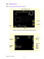
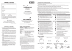
2.2.1 Jumper and Connector Location
1*DDR2 SODIMM up to 2G
SATA1
SATA2
FAN1
SDVO
Figure 2.1 Jumper and Connector layout (Component side)
X4: 100pins
-IDE
-Ethernet
X2: 100pins
-ISA Bus
X3: 100pins
-VGA
-LVDS
-TV Out
-COM
-LPT/FDD
-IrDA
-Keyboard
-Mouse
X1: 100pins
-PCI Bus
-USB
-Audio
Figure 2.2 Jumper and Connector layout (Solder side)
SOM-4461 User Manual
10
Chapter 2
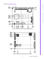
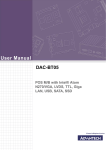
2.2.2 Board Dimension
H/W installation
Figure 2.3 Board Dimension layout (Component side)
Figure 2.4 Board Dimension layout (Solder side)
11
SOM-4461 User Manual
2.2.3 Heat spreader Dimension
Figure 2.5 Drawing of Heatspreader for BGA type CPU
2.2.4 Thermal Solution
Important notice:
1. Please note - the heat-spreader shipped with Advantech’s SOM product is not a
"COMPLETE" thermal solution. The function of this heat-spreader is for conducting heat from SOM module to the customer's own heat-sink or cooler which
is added onto this heat-spreader.
2. An extra efficient heat-sink or cooler is required to add onto this heat-spreader
to ensure the SOM module can work appropriately.
3. An inefficient heat-sink or cooler may damage the SOM module. This kind of
damage will invalidate the product warranty
4. Advantech is able to provide optional heat-sinks or coolers for the SOM module,
please contact your sales representative for details
5. Please make sure the heat spreader temperature for the CPU module stays
under 60°C.
For more information please refer to Advantech_ETX_DesignGuide, Chapter 8.
You could download Advantech_ETX_DesignGuide from http://com.advantech.com/
SOM-4461 User Manual
12
Chapter
3
BIOS settings
3
3.1 BIOS Introduction
AwardBIOS 6.0 is a full-featured BIOS provided by Advantech to deliver superior performance, compatibility, and functionality to industrial PCs and embedded boards. Its
many options and extensions let you customize your products to a wide range of
designs and target markets.
The modular, adaptable AwardBIOS 6.0 supports the broadest range of third-party
peripherals and all popular chipsets, plus Intel, AMD, nVidia, VIA, and compatible
CPUs from 386 through Pentium, AMD Geode, K7 and K8 (including multiple processor platforms), and VIA Eden C3 and C7 CPUs.
You can use Advantech's utilities to select and install features that suit your needs
and your customers' needs.
3.2 BIOS Setup
The SOM-4461 system has AwardBIOS 6.0 built-in, which includes a CMOS SETUP
utility that allows users to configure settings as required or to activate certain system
features.
The CMOS SETUP saves configuration settings in the CMOS RAM of the motherboard. When the system power is turned off, the onboard battery supplies the necessary power to the CMOS RAM so that settings are retained.
To access the CMOS SETUP screen, press the <Del> button during the power-on
BIOS POST (Power-On Self Test).
CMOS SETUP Navigation and Control Keys:
< ↑ >< ↓ >< ← >< → >
Move to highlight item
<Enter>
Select Item
<Esc>
Main Menu - Start Quit sequence
Sub Menu - Exit the current page and return to level above
<Page Up/+>
Increase the numeric value or make changes
<Page Down/->
Decrease the numeric value or make changes
<F1>
General help, for Setup Sub Menu
<F2>
Item Help
<F5>
Load Previous Values
<F7>
Load Optimized Defaults
<F10>
Save all CMOS changes
SOM-4461 User Manual
14
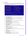
Press the <Del> key during startup to enter the BIOS CMOS Setup Utility; the Main
Menu will appear on the screen. Use arrow keys to highlight the desired item, and
press <Enter> to accept, or enter the sub-menu.
Chapter 3
3.2.1 Main Menu
BIOS settings
!
!
!
!
!
!
!
!
!
!
!
!
Standard CMOS Features
This setup page includes all the features for standard CMOS configuration.
Advanced BIOS Features
This setup page includes all the features for advanced BIOS configuration.
Advanced Chipset Features
This setup page includes all the features for advanced chipset configuration.
Integrated Peripherals
This setup page includes all onboard peripheral devices.
Power Management Setup
This setup page includes all the power management items.
PnP/PCI Configurations
This setup page includes PnP OS and PCI device configuration.
PC Health Status
This setup page includes the system auto-detect CPU and system temperature,
voltage.
Frequency/Voltage Control
This setup page includes CPU host clock control.
Load Optimized Defaults
This selection loads optimized values for best system performance configuration.
Set Password
Establish, change or disable passwords.
Save & Exit Setup
Save CMOS value settings to CMOS and exit BIOS setup.
Exit Without Saving
Abandon all CMOS value changes and exit BIOS setup.
15
SOM-4461 User Manual
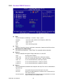
3.2.2 Standard CMOS Features
!
!
!
!
Date
The date format is <weekday>, <month>, <day>, <year>.
Weekday
From Sun to Sat, determined and display by BIOS only
Month
From Jan to Dec.
Day
From 1 to 31
Year
From 1999 through 2098
Time
The time format in <hours>:<minutes>:<seconds>, based on the 24-hour time.
IDE Channel 0/1 Master/Slave
IDE HDD Auto-Detection - Press "Enter" for automatic device detection.
Drive A
The Item identifies the types of floppy disk drive A or drive B
!
None
No floppy drive installed
360K, 5.25"
5.25 inch PC-type standard drive; 360K byte capacity
1.2M, 5.25"
5.25 inch AT-type high-density drive; 1.2M byte capacity
720K, 3.5"
3.5 inch double-sided drive; 720K byte capacity
1.44M, 3.5"
3.5 inch double-sided drive; 1.44M byte capacity
2.88M, 3.5"
3.5 inch double-sided drive; 2.88M byte capacity
Halt on
This item determines whether the computer will stop if an error is detected during power up.
No Errors
The system boot process will not stop for any error
All Errors
Whenever the BIOS detects a non-fatal error the system boot process will be stopped.
All, But Keyboard
The system boot process will not stop for a keyboard error, but will
stop for all other errors. (Default value)
SOM-4461 User Manual
16
!
All, But Disk/Key
The system boot process will not stop for a keyboard or disk error,
but will stop for all other errors.
Base Memory
Displays the amount of base (or conventional) memory installed in the system.
Extended Memory
Displays the amount of extended memory (above 1 MB in CPU's memory
address map) installed in the system.
Total Memory
Displays the total system memory size.
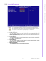
3.2.3 Advanced BIOS Features
!
!
!
!
!
!
Blank Boot
[Disabled]
This item allows the user to enable/disable BIOS POST screen output.
POST Beep
[Enabled]
This item allows the user to enable/disable POST beep sound.
CPU Feature
This item allows the user to adjust CPU settings such as CPU ratio, VID and
Thermal, and special features like XD flag.
Hard Disk Boot Priority
This item allows the user to select the boot sequence for system devices such
as HDD, SCSI, and RAID.
USB Boot Priority
This item allows the user to select the boot sequence for USB devices.
CPU L3 Cache
[Enabled]
This item allows the user to enable/disable CPU L3 cache.
17
SOM-4461 User Manual
BIOS settings
!
The system boot process will not stop for a diskette error, but will
stop for all other errors.
Chapter 3
!
All, But Diskette
!
!
!
!
!
!
!
!
!
!
!
Hyper-Threading Technology
[Enabled]
This item allows the user to enable/disable Hyper-threading support for the
Intel® Pentium® 4 processor with HT Technology.
Quick Power On Self Test
[Enabled]
This field speeds up the Power-On Self Test (POST) routine by skipping re-testing a second, third and fourth time. The default setting is enabled.
First / Second / Third / Other Boot Drive
Hard Disk
Sets boot priority for the hard disk.
USB devices
Sets boot priority forUSB devices.
CDROM
Sets boot priority for CDROM.
USB-FDD
Sets boot priority for USB-FDD.
USB-ZIP
Sets boot priority for USB-ZIP.
USB-CDROM
Sets boot priority for USB-CDROM.
LAN
Sets boot priority for LAN.
Disabled
Disables this boot function.
Boot Up NumLock Status
[On]
This item allows the user to activate the Number Lock key at system boot.
Gate A20 Option [Fast]
This item allows the user to switch on or off A20 control by port 92.
Typematic Rate Setting
This item allows the user to set the two typematic control items.
This field controls the speed of
– Typematic Rate (Chars/Sec)
This item controls the speed at which the system registers auto repeated keystrokes.
The eight settings are: 6, 8, 10, 12, 15, 20, 24 and 30.
– Typematic Delay (Msec)
This item sets the key press delay time before auto repeat begins. The four
delay rate options are: 250, 500, 750 and 1000.
Security Option
[Setup]
System
System requires correct password before booting, and also before
permitting access to the Setup page.
Setup
System will boot, but requires correct password before permitting
access to Setup. (Default value)
APIC Mode
[Enabled]
This item allows the user to enable/disable the "Advanced Programmable Interrupt Controller". APIC is implemented in the motherboard and must be supported by the operating system; it extends the number of IRQs available.
MPS Version Control for OS
[1.4]
This item sets the operating system multiprocessor support version.
OS Select For DRAM > 64 MB
[Non-OS2]
Select OS2 only if the system is running the OS/2 operating system with greater
than 64 MB of RAM on the system.
Full Screen LOGO Show
[Enabled]
This item allows the user to set if the BIOS should show the full screen logo or
not.
! Summary Screen Show
SOM-4461 User Manual
[Enabled]
18
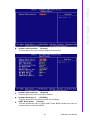
3.2.4 Advanced Chipset Features
Chapter 3
This item allows the user to set if the BIOS should show the summary screen or
not.
BIOS settings
Note!
The "Advanced Chipset Features" screen controls the configuration of
the board's chipset register settings and performance tuning - the
options on this screen may vary depending on the chipset type. It is
strongly recommended that only technical users make changes to the
default settings.
DRAM Timing Selectable [By SPD]
This item enables users to set the optimal timings for items 2 through 5. The
system default setting of "By SPD" follows the SPD information and ensures the
system running stable and at optimal performance.
! CAS Latency Time [Auto]
This item enables users to set the timing delay in clock cycles before SDRAM
starts a read command after receiving it.
! DRAM RAS# to CAS# Delay [Auto]
This item enables users to set the timing of the transition from RAS (row
address strobe) to CAS (column address strobe) as both rows and column are
separately addressed shortly after DRAM is refreshed.
! DRAM RAS# Precharge [Auto]
This item enables users to set the DRAM RAS# precharge timing, system
default is setting to "Auto" to reference the data from SPD ROM.
! Precharge delay (tRAS) [Auto]
This item allows user to adjust memory precharge time
! System Memory Frequency [Auto]
This item allows the user to adjust memory frequency to improvement performance.
! SLP_S4# Assertion Width [4 to 5 Sec]
!
19
SOM-4461 User Manual
!
!
!
!
!
!
!
!
!
!
This item allow the user to set the SLP_S4# Assertion Width.
System BIOS Cacheable [Enabled]
This item allows the system BIOS to be cached to allow faster execution and
better performance.
Video BIOS Cacheable [Disabled]
This item allows the video BIOS to be cached to allow faster execution and better performance.
Memory Hole At 15M-16M [Disabled]
This item reserves 15MB-16MB memory address space to ISA expansion cards
that specifically require the setting. Memory from 15MB-16MB will be unavailable to the system because of the expansion cards can only access memory at
this area.
PCI Express Root Port Func
[Press Enter]
This item allows the user to adjust the PCIE port to on, off, or auto.
On-Chip Frame Buffer Size [8MB]
This item allows the user to adjust on-chip graphics of memory buffer.
DVMT Mode [DVMT]
This item allows the user to adjust Intel's Dynamic Video Memory Technology
(DVMT).Bios provide three option to choose (DVMT,FIXED and Both).
DVMT/FIXED Memory Size [128MB]
This item allows the user to adjust DVMT/FIXED graphics memory size.
Boot Display
[CRT]
This item allows the user to decide which display mode to use for the boot display.
Panel Type
[ 800 x 600, 18bits]
This item allows the user to adjust panel resolution.
LCD BackLight
[High Active]
This item allows the user to adjust the polarity to enable LCD backlight.
SOM-4461 User Manual
20
Chapter 3
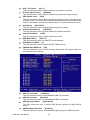
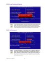
3.2.5 Integrated Peripherals
BIOS settings
Note!
!
!
!
!
The "Integrated Peripherals" screen controls chipset configuration for
IDE, ATA, SATA, USB, AC97, MC97 and Super IO and Sensor devices.
The options on this screen vary depending on the chipset.
OnChip IDE Device
This item enables users to set the OnChip IDE device status, including IDE
devices and setting PIO and DMA access modes. Some chipsets support newer
SATA devices (Serial-ATA).
Onboard Device
This item enables users to set the Onboard device status, includes enable USB,
AC97, MC97 and LAN devices.
Super IO Device
This item enables users to set the Super IO device status, includes enable
Floppy, COM, LPT and Power fail status.
USB Device Setting
This item enables users to set the USB device type.
21
SOM-4461 User Manual
!
!
!
!
!
!
!
!
!
IDE HDD Block Mode
[Enabled]
This item allows the user to enable block mode for HDD.
IDE DMA transfer access
[Enabled]
This item allows the user to enable block mode for DMA.
On-Chip Primary PCI IDE
[Enabled]
This item allows the user to enable On-Chip IDE controller.
IDE HDD Primary Master/Slave PIO/UDMA
[ Auto]
This item allows the user to set PIO/UDMA mode for HDD.
On-Chip Secondary PCI IDE
[Enabled]
This item allows the user to enable On-Chip IDE controller.
IDE HDD Secondary Master/Slave PIO/UDMA
[ Auto]
This item allows the user to set PIO/UDMA mode for HDD.
On-Chip Serial ATA
[Enhanced Mode]
This item allows the user to set On-Chip serial ATA controller mode.
SATA Port Speed Settings
[Disabled]
This item allows the user to manual set SATA port speed.
PATA IDE Mode
[Secondary]
This item shows current PATA IDE mode.
SOM-4461 User Manual
22
Chapter 3
BIOS settings
!
Onboard LAN Controller [Enabled]
This item allows the user to enable/disable Onboard LAN.
!
Onboard FDC Controller
[Enabled]
This item allows the user to set FDC controller.
Onboard Serial port 2
[ 2F8/IRQ3]
This item allows the user to adjust serial port 2 address.
!
!
UART Mode Select
[Normal]
This item allows the user to adjust UART mode. BIOS provide three item for
choose (Normal, IrDA and ASKIR).
23
SOM-4461 User Manual
!
!
!
!
!
!
!
!
!
!
!
!
!
RxD , TxD Active
[Hi,Lo]
This item allows the user to adjust infrared ray transition of polarity.
IR Transmission Delay
[Enabled]
This item allows the user to adjust infrared ray transmission delay function.
UR2 Duplex mode
[Half]
This item allows the user to adjust infrared ray duplex function. Two options are
provided. (half, Full) Full-duplex mode permits simultaneous two-direction transmission. Half-duplex mode permits transmission in only one direction at a time.
Use IR Pins
[IR-Rx2Tx2]
This item allows the user to adjust infrared ray pins of options.
Onboard Parallel Port
[378/IRQ7]
This item allows the user to adjust parallel port address and IRQ.
Parallel Port Mode
[SPP]
This item allows the user to adjust parallel port mode.
EPP Mode Select
[EPP1.7]
This item allows the user to select EPP mode standard.
ECP Mode Use DMA
[3]
This item allows the user to adjust the ECP DMA resource.
PWRON After PWR-Fail [Off]
This item allows the user to select recovery after power fail function; this function depends on the chipset.
USB 1.0 Controller
[ Enabled]
This item allows the user to enable/disable USB 1.0 Controller.
USB 2.0 Contoller
[Enabled]
This item allows the user to enable/disable USB 2.0 Controller.
USB Operation Mode
[High Speed]
This item allows the user to adjust USB devices operate at High/Full/Low
speed.
USB Keyboard Function
[Enabled]
This item allows the user to enable/disable legacy support of USB Keyboard.
SOM-4461 User Manual
24
!
!
USB Mouse Function
[Enabled]
This item allows the user to enable/disable legacy support of USB Mouse.
USB Storage Function
[Enabled]
This item allows the user to enable/disable legacy support of USB Mass Storage
USB Mass Storage Device Boot Setting
This items list USB Mass Storage devices connected and allows the user to set
Mass Storage type.
Note!
!
!
!
BIOS settings
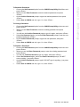
3.2.6 Power Management Setup
Chapter 3
!
The "Power Management Setup" screen allows configuration of the system for effective energy savings while still operating in a manner consistent with intended computer use.
ACPI Function [Enabled]
This item defines the ACPI (Advanced Configuration and Power Management)
feature that makes hardware status information available to the operating system, and communicate PC and system devices for improving the power management.
ACPI Suspend Type [S3 (STR)]
This item allows the user to select sleep state state when the computer is in
suspend mode.
S1 (POS)
The suspend mode is equivalent to a software power down.
S3 (STR)
The system shuts down with the exception of a refresh current to
the system memory.
Run VGABIOS if S3 Resume° [Auto[
This item allows the user to enable run VGA bios if system resume from S3.
25
SOM-4461 User Manual
!
!
Power Management [Min Saving]
This item allows the user to select system power saving mode.
Min Saving
Minimum power management. Suspend Mode=1 hr.
Max Saving
Maximum power management. Suspend Mode=1 min.
User Defined
Allows the user to set each mode individually.
Suspend Mode= Disabled or 1 min ~1 hr.
Video Off Method
[DPMS]
This item allows the user to determine the manner in which the monitor is
blanked.
V/H SYNC+Blank
!
!
!
!
!
!
This option will cause the system to turn off vertical and horizontal
synchronization ports and write blanks to the video buffer.
Blank Screen
This option only writes blanks to the video buffer.
DPMS
Initial display power management signaling.
Video Off In Suspend
[Yes]
This item allows the user to turn off video during system enter suspend mode.
Suspend Type
[Stop Grant]
This item allows the user to determine the suspend type.
Modem use IRQ
[3]
This item allows the user to determine the IRQ which the MODEM can use.
Suspend Mode
[1 Hour]
This item allows the user to determine the time of system inactivity, all devices
except the CPU will be shut off.
HDD Power Down Mode
[15 Min]
This item allows the user to determine the time of system inactivity, the hard
disk drive will be powered down.
Soft-Off by PWR-BTTN
[Instant-Off]
This item allows the user to define the power button functions.
!
!
!
!
!
Instant-Off
Press the power button to power off instantly.
Delay 4 Sec
Press and hold the power button for 4 sec to power off.
Wake-Up by PCI card
[Enabled]
This item allows the user to enable and define how PCI cards wake the system
up from suspend mode
Power On by Ring
[Enabled]
This item allows the user to define the system will resume by activating of
modem ring.
USB KB Wake-Up From S3
[Disabled]
This item allows the user to enable and define how the system will wakeup by
activation of the USB keyboard in S3 mode.
Resume by Alarm
[Disabled]
This item allows the user to enable and key in Date/time to power on system.
Disabled
Disable this function.
Enabled
Enable alarm function to power on system
Day (of month) Alarm
1-31
Time (HH:MM:SS) Alarm
(0-23) : (0-59) : 0-59)
Reload Global Timer Events
This item allows the user to select the events to reload global timer for legacy
power management.
SOM-4461 User Manual
26
Chapter 3
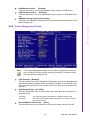
3.2.7 PnP/PCI Configurations
BIOS settings
Note!
!
!
!
!
!
!
This "PnP/PCI Configurations" option sets up the IRQ and DMA (both
PnP and PCI bus assignments).
Init Display First
[PCI Slot]
This item is setting for start up video output from PCI or Onboard device.
Reset Configuration Data
[Disabled]
This item allow the user to clear any PnP configuration data stored in the BIOS.
Resources Controlled By
[Auto (ESCD)]
– IRQ Resources
This item allows you respectively assign an interruptive type for IRQ-3, 4, 5,
7, 9, 10, 11, 12, 14, and 15.
– DMA Resources
This item allows you respectively assign an interruptive type for DMA, 0, 1, 2,
3, 4, 5, 6, and 7.
PCI VGA Palette Snoop
[Disabled]
The item is designed to solve problems caused by some non-standard VGA
cards. A built-in VGA system does not need this function.
INT Pin 1~8 Assignment
[Auto]
This item allows the user to select the interrupt request (IRQ) assigned to a
device connected to the PCI interface on your system.
Maximum Payload Size
[4096]
This item allows the user to adjust maximum TLP (Transaction Layer Packet)
payload size.
27
SOM-4461 User Manual
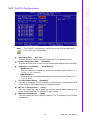
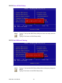
3.2.8 PC Health Status
Note!
!
!
!
!
The “PC Health Status” screen controls the thermal, fan, and voltage
status of the board. The options on this page vary depending on the
chipset.
Shutdown Temperature
[Disabled]
This item allows the user to set the temperature to notify the ACPI OS to shutdown the system.
Current System Temp.
[Show Only]
This item displays current board temperature.
Current CPU1 Temperature
[Show Only]
This item displays current CPU temperature.
CPU VCore/+5V/+5VSB/+1.5V/1.8 V
[Show Only]
This item displays current CPU and system voltage.
SOM-4461 User Manual
28
Chapter 3
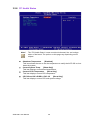
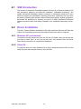
3.2.9 Frequency/Voltage Control
BIOS settings
Note!
!
!
!
!
The "Frequency/Voltage Control" screen controls the CPU host and PCI
frequency. The options on this page vary depending on the chipset;
items show up according to installed CPU capacities.
CPU CIock Ratio
[6X]
This item enables users to set the CPU clock ratio manually.
Auto Detect PCI Clk
[Enabled]
This item enables users to set the PCI Clk either by automatic system detection
or manually.
Spread Spectrum
[Disabled]
This item enables users to set the spread spectrum modulation.
CPU Host/SRC/PCI Clock
[Defautl]
This item enables users to set the CPUhost/SRC/PCI clock.
29
SOM-4461 User Manual
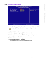
3.2.10 Load Optimized Defaults
Note!
"Load Optimized Defaults" loads the default system values directly from
ROM. If the stored record created by the setup program should ever
become corrupted (and therefore unusable), select Load Setup Defaults
to have these default values load automatically for the next bootup.
3.2.11 Set Password
Note!
To enable this feature, you should first go to the "Advanced BIOS Features" menu, choose the Security Option, and select either System or
Setup, depending on which aspects you want password protected. System requires a password both to boot the system and to enter Setup.
Setup requires a password only to enter Setup. A password may be at
most 8 characters long.
SOM-4461 User Manual
30
To Establish Password
1. Choose the Set Password option from the CMOS Setup Utility Main Menu and
press <Enter>.
2. When you see Enter Password, enter the desired password and press
<Enter>.
3. At the Confirm Password prompt, retype the desired password, then press
<Enter>.
4. Select Save to CMOS and exit, type <Y>, then <Enter>.
Chapter 3
To Change Password
1. Choose the Set Password option from the CMOS Setup Utility main menu and
press <Enter>.
2. When you see Enter Password, enter the existing password and press
<Enter>.
3. You will see the Confirm Password prompt, type it in again, and press <Enter>.
4. Select Set Password again, and at the Enter Password prompt, enter the new
password and press <Enter>.
5. At the Confirm Password prompt, retype the new password, and press
<Enter>.
6. Select Save to CMOS and exit, type <Y>, then <Enter>.
BIOS settings
To Disable a Password
1. Choose the Set Password option from the CMOS Setup Utility main menu and
press <Enter>.
2. When you see the Enter Password prompt, enter the existing password and
press <Enter>.
3. You will see Confirm Password, type it in again, and press <Enter>.
4. Select Set Password again, and at the Enter Password prompt, DO NOT
enter anything - just press <Enter>.
5. At the Confirm Password prompt, again, DO NOT type in anything - just press
<Enter>.
6. Select Save to CMOS and exit, type <Y>, then <Enter>.
31
SOM-4461 User Manual
3.2.12 Save & Exit Setup
Note!
Typing "Y" will quit the BIOS Setup Utility and save user setup values to
CMOS.
Typing "N" will return to BIOS Setup Utility.
3.2.13 Quit Without Saving
Note!
Typing "Y" will quit the BIOS Setup Utility without saving any changes to
CMOS.
Typing "N" will return to the BIOS Setup Utility.
SOM-4461 User Manual
32
Chapter
4
4
S/W Introduction &
Installation
4.1 S/W Introduction
The mission of Advantech Embedded Software Services is to "Enhance quality of life
with Advantech platforms and Microsoft Windows? embedded technology." We
enable Windows® Embedded software products on Advantech platforms to more
effectively support the embedded computing community. Customers are freed from
the hassle of dealing with multiple vendors (Hardware suppliers, System integrators,
Embedded OS distributor) for projects. Our goal is to make Windows® Embedded
Software solutions easily and widely available to the embedded computing community.
4.2 Driver Installation
The Intel? Chipset Software Installation (CSI) utility installs the Windows INF files that
outline to the operating system how the chipset components will be configured.
4.2.1 Windows XP professional
To install the drivers please just insert the CD into CD-ROM, select the drivers that
you want to install, then run .exe (set up) file under each chipset folder and follow
Driver Setup instructions to complete the installation.
4.2.2 Other OS
To install the drivers for Other Windows OS or Linux, please browse the CD to run the
setup file under each chipset folder on the CD-ROM.
SOM-4461 User Manual
34
Appendix
A
A
Watchdog Timer
This appendix gives you information about the watchdog timer
programming on the SOM-4461
CPU System on Module
Sections include:
! Watchdog Timer Programming
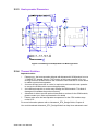
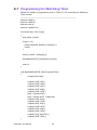
A.1 Programming the Watchdog Timer
Bellow is a sample of programming code in Turbo C++ for controlling the Watchdog
Timer function.
--------------------------------------------------------------------------------------------#include <stdio.h>
#include <stdlib.h>
#include <dos.h>
#include "wdt83627.h"
int main(int argc, char* argv[])
{
long reboot_counter;
if (argc != 2) {
printf("Parameter Number is Wrong!!\n");
exit(0);
}
reboot_counter = atol(argv[1]);
StartWdtW836272E_DHG(reboot_counter);
return 0;
}
void StartWdtW836272E_DHG (long SpecTime)
{
unsigned char temp;
outportb( 0x2E, 0x87 );
outportb( 0x2E, 0x87 );
outportb( 0x2E, 0x07 );
outportb( 0x2F, 0x08 );
outportb( 0x2E, 0x2D );
temp = inportb( 0x2F );
temp = temp & 0xFE; // Mask bit0
outportb( 0x2F, temp );
outportb( 0x2E, 0x30 );
outportb( 0x2F, 0x01 );
outportb( 0x2E, 0xF5 );
outportb( 0x2F, 0x00 );
outportb( 0x2E, 0xF6 );
outportb( 0x2F, SpecTime );
outportb( 0x2E, 0xAA );
}
SOM-4461 User Manual
36
Appendix
B
B
System Assignments
This appendix gives you the information about the system resource
allocation on the SOM-4461 CPU
System on Module
Sections include:
! System I/O ports
! DMA Channel Assignments
! Interrupt Assignments
! 1st MB Memory Map
B.1 System I/O Ports
Table B.1: System I/O ports
Addr. range(Hex)
Device
0000 - 0CF7
PCI bus
0000 - 000F
Direct memory access controller
0010 - 001F
Motherboard resources
0020 - 0021
Programmable interrupt controller
0022 - 003F
Motherboard resources
0040 - 0043
System timer
0044 - 005F
Motherboard resources
0060 - 0060
Standard 101/102-Key or Microsoft Natural PS/2 Keyboard
0061 - 0061
System speaker
0062 - 0063
Motherboard resources
0064 - 0064
Standard 101/102-Key or Microsoft Natural PS/2 Keyboard
0065 - 006F
Motherboard resources
0070 - 0073
System CMOS/real time clock
0074 - 007F
Motherboard resources
0080 - 0090
Direct memory access controller
0091 - 0093
Motherboard resources
0094 - 009F
Direct memory access controller
00A0 - 00A1
Programmable interrupt controller
00A2 - 00BF
Motherboard resources
00C0 - 00DF
Direct memory access controller
00E0 - 00EF
Motherboard resources
00F0 - 00FF
Numeric data processor
01F0 - 01F7
Primary IDE Channel
0274 - 0277
ISAPNP Read Data Port
0279 - 0279
ISAPNP Read Data Port
02F8 - 02FF
Communications Port (COM2)
0378 - 037F
Printer Port (LPT1)
03B0 - 03BB
Intel Corporation US15 Embedded Graphics
03C0 - 03DF
Intel Corporation US15 Embedded Graphics
03F6 - 03F6
Primary IDE Channel
03F8 - 03FF
Communications Port (COM1)
04D0 - 04D1
Motherboard resources
0500 - 051F
Intel(R) SCH Family SMBus Controller
0778 - 077B
Printer Port (LPT1)
0880 - 088F
Motherboard resources
0A78 - 0A7B
Motherboard resources
0B78 - 0B7B
Motherboard resources
0BBC - 0BBF
Motherboard resources
0D00 - FFFF
PCI bus
0E78 - 0E7B
Motherboard resources
0F78 - 0F7B
Motherboard resources
0FBC - 0FBF
Motherboard resources
D000 - DFFF
Intel(R) SCH Family PCI Express Root Port 3 - 8112
DF00 - FF3F
Intel(R) PRO/100 VE Network Connection
SOM-4461 User Manual
38
E000 - EFFF
Intel(R) SCH Family PCI Express Root Port 1 - 8110
FB00 - FB0F
Standard Dual Channel IDE Controller
FC00 - FC1F
Intel(R) SCH Family USB Universal Host Controller - 8116
FD00 - FD1F
Intel(R) SCH Family USB Universal Host Controller - 8115
FE00 - FE1F
Intel(R) SCH Family USB Universal Host Controller - 8114
FF00 - FF07
Intel Corporation US15 Embedded Graphics
B.2 DMA Channel Assignments
Note!
SOM-4461 support DMA function by request.
B.3 Interrupt Assignments
Table B.2: Interrupt assignments
Interrupt#
Interrupt source
NMI
Parity error detected
IRQ 0
System timer / High precision event timer
IRQ 1
Standard 101/102-Key or Microsoft Natural PS/2 Keyboard
IRQ 2
Available
IRQ 3
Communications Port (COM2)
IRQ 4
Communications Port (COM1)
IRQ 5
Available
IRQ 6
Available
IRQ 7
Available
IRQ 8
System CMOS/real time clock
IRQ 9
Microsoft ACPI-Compliant System
IRQ 10
Available
IRQ 11
Available
IRQ 12
PS/2 Compatible Mouse
IRQ 13
Numeric data processor
IRQ 14
Primary IDE Channel
IRQ 15
Available
IRQ 16
Intel(R) SCH Family PCI Express Root Port 1 - 8110
(R) SCH Family USB Universal Host Controller - 8114
Microsoft UAA Bus Driver for High Definition Audio
SDA Standard Compliant SD Host Controller
IRQ 17
Intel(R) PRO/100 VE Network Connection
Intel(R) SCH Family PCI Express Root Port 3 - 8112
Intel(R) SCH Family USB Universal Host Controller - 8115
SDA Standard Compliant SD Host Controller
IRQ 18
Intel(R) SCH Family USB Universal Host Controller - 8116
SDA Standard Compliant SD Host Controller
IRQ 19
Intel(R) SCH Family USB2 Enhanced Host Controller - 8117
USB and Ethernet IRQ is automatically set by the system
39
SOM-4461 User Manual
Appendix B System Assignments
Table B.1: System I/O ports
B.4 1st MB Memory Map
Table B.3: 1st MB memory map
Addr. range (Hex)
Device
00000000 - 0009FFFF
System board
000A0000 - 000BFFFF
PCI bus
000A0000 - 000BFFFF
Intel Corporation US15 Embedded Graphics
000C0000 - 000DFFFF
PCI bus
000E0000 - 000EFFFF
PCI bus
000F0000 - 000FFFFF
System board
00100000 - 7F6DFFFF
System board
7F6E0000 - 7F7FFFFF
System board
7F800000 - FEBFFFFF
PCI bus
D8000000 - DFFFFFFF
Intel Corporation US15 Embedded Graphics
E0000000 - EFFFFFFF
Motherboard resources
FDA00000 - FDCFFFFF
Intel(R) SCH Family PCI Express Root Port 3 - 8112
FDCC0000 - FDCDFFFF
Intel(R) PRO/100 VE Network Connection
FDCFF000 - FDCFFFFF
Intel(R) PRO/100 VE Network Connection
FDD00000 - FDEFFFFF
Intel(R) SCH Family PCI Express Root Port 1 - 8110
FDF00000 - FDF7FFFF
Intel Corporation US15 Embedded Graphics
FDFC0000 - FDFDFFFF
Intel Corporation US15 Embedded Graphics
FDFF8000 - FDFFBFFF
Microsoft UAA Bus Driver for High Definition Audio
FDFFC000 - FDFFC0FF
SDA Standard Compliant SD Host Controller
FDFFD000 - FDFFD0FF
SDA Standard Compliant SD Host Controller
FDFFE000 - FDFFE0FF
SDA Standard Compliant SD Host Controller
FDFFF000 - FDFFF3FF
Intel(R) SCH Family USB2 Enhanced Host Controller - 8117
FEC00000 - FEC00FFF
System board
FED00000 - FED000FF
System board
FED00000 - FED003FF
High precision event timer
FED13000 --FED1DFFF
System board
FED20000 - FED8FFFF
System board
FEE00000 - FEE00FFF
System board
FFB00000 - FFB7FFFF
System board
FFB80000 - FFBFFFFF
Intel(R) 82802 Firmware Hub Device
FFF00000 - FFFFFFFF
System board
SOM-4461 User Manual
40
Appendix B System Assignments
SOM-4461 User Manual
41
www.advantech.com
Please verify specifications before quoting. This guide is intended for reference
purposes only.
All product specifications are subject to change without notice.
No part of this publication may be reproduced in any form or by any means,
electronic, photocopying, recording or otherwise, without prior written permission of the publisher.
All brand and product names are trademarks or registered trademarks of their
respective companies.
© Advantech Co., Ltd. 2009