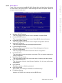
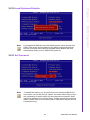
1
User Manual
SOM-5786
Copyright
The documentation and the software included with this product are copyrighted 2008
by Advantech Co., Ltd. All rights are reserved. Advantech Co., Ltd. reserves the right
to make improvements in the products described in this manual at any time without
notice. No part of this manual may be reproduced, copied, translated or transmitted
in any form or by any means without the prior written permission of Advantech Co.,
Ltd. Information provided in this manual is intended to be accurate and reliable. However, Advantech Co., Ltd. assumes no responsibility for its use, nor for any infringements of the rights of third parties, which may result from its use.
Acknowledgements
SOM and DTOS are trademarks of Advantech Co., Ltd.
AMD is a trademark of Advanced Micro Devices, Inc.
Award is a trademark of Award Software International, Inc.
Cyrix is a trademark of Cyrix Corporation.
IBM, PC/AT, PS/2 and VGA are trademarks of International Business Machines Corporation.
Intel® and Pentium® are trademarks of Intel Corporation.
Microsoft Windows® is a registered trademark of Microsoft Corp.
RTL is a trademark of Realtek Semiconductor Co., Ltd.
C&T is a trademark of Chips and Technologies, Inc.
UMC is a trademark of United Microelectronics Corporation.
Winbond is a trademark of Winbond Electronics Corp.
STPC is a trademark of SGS Thomson Corp.
For more information on this and other Advantech products, please visit our website
at:
http://www.advantech.com
For technical support and service, please visit our support website at:
http://support.advantech.com
This manual is for the SOM-5786.
SOM-5786 User Manual
Part No. 2006578600
Edition 1
Printed in China
July 2008
ii
Declaration of Conformity
CE
This product has passed the CE test for environmental specifications. Test conditions
for passing included the equipment being operated within an industrial enclosure. In
order to protect the product from being damaged by ESD (Electrostatic Discharge)
and EMI leakage, we strongly recommend the use of CE-compliant industrial enclosure products.
FCC Class A
Note: This equipment has been tested and found to comply with the limits for a Class
A digital device, pursuant to part 15 of the FCC Rules. These limits are designed to
provide reasonable protection against harmful interference when the equipment is
operated in a commercial environment. This equipment generates, uses, and can
radiate radio frequency energy and, if not installed and used in accordance with the
instruction manual, may cause harmful interference to radio communications. Operation of this equipment in a residential area is likely to cause harmful interference in
which case the user will be required to correct the interference at his own expense.
Caution! There is a danger of a new battery exploding if it is incorrectly installed.
Do not attempt to recharge, force open, or heat the battery. Replace the
battery only with the same or equivalent type recommended by the manufacturer. Discard used batteries according to the manufacturer's
instructions.
iii
SOM-5786 User Manual
Technical Support and Assistance
1.
2.
Visit the Advantech web site at www.advantech.com/support where you can find
the latest information about the product.
Contact your distributor, sales representative, or Advantech's customer service
center for technical support if you need additional assistance. Please have the
following information ready before you call:
– Product name and serial number
– Description of your peripheral attachments
– Description of your software (operating system, version, application software,
etc.)
– A complete description of the problem
– The exact wording of any error messages
Document Feedback
To assist us in making improvements to this manual, we would welcome comments
and constructive criticism. Please send all such - in writing to:
[email protected]
Packing List
Before setting up the system, check that the items listed below are included and in
good condition. If any item does not accord with the table, please contact your dealer
immediately.
! Before you begin installing your card, please make sure that the following materials have been shipped:
! SOM-5786 System On Module CPU module
! CD-ROM or Disks for utility, drivers, and manual (in PDF format)
! Heatspreader
SOM-5786 User Manual
iv
Safety Instructions
1.
2.
3.
4.
5.
6.
7.
8.
9.
10.
11.
12.
13.
14.
Read these safety instructions carefully.
Keep this User Manual for later reference.
Disconnect this equipment from any AC outlet before cleaning. Use a damp
cloth. Do not use liquid or spray detergents for cleaning.
For plug-in equipment, the power outlet socket must be located near the equipment and must be easily accessible.
Keep this equipment away from humidity.
Put this equipment on a reliable surface during installation. Dropping it or letting
it fall may cause damage.
The openings on the enclosure are for air convection. Protect the equipment
from overheating. DO NOT COVER THE OPENINGS.
Make sure the voltage of the power source is correct before connecting the
equipment to the power outlet.
Position the power cord so that people cannot step on it. Do not place anything
over the power cord.
All cautions and warnings on the equipment should be noted.
If the equipment is not used for a long time, disconnect it from the power source
to avoid damage by transient overvoltage.
Never pour any liquid into an opening. This may cause fire or electrical shock.
Never open the equipment. For safety reasons, the equipment should be
opened only by qualified service personnel.
If one of the following situations arises, get the equipment checked by service
personnel:
– The power cord or plug is damaged.
– Liquid has penetrated into the equipment.
– The equipment has been exposed to moisture.
– The equipment does not work well, or you cannot get it to work according to
the user's manual.
– The equipment has been dropped and damaged.
– The equipment has obvious signs of breakage.
Safety Precaution - Static Electricity
Follow these simple precautions to protect yourself from harm and the products from
damage.
! To avoid electrical shock, always disconnect the power from your PC chassis
before you work on it. Don't touch any components on the CPU card or other
cards while the PC is on.
! Disconnect power before making any configuration changes. The sudden rush
of power as you connect a jumper or install a card may damage sensitive electronic components.
v
SOM-5786 User Manual
SOM-5786 User Manual
vi
Contents
Chapter
Chapter
1
General Information ............................1
1.1
1.2
Introduction ............................................................................................... 2
Specifications ............................................................................................ 3
1.2.1 Standard System On Module functions ........................................ 3
1.2.2 VGA/flat panel Interface................................................................ 3
1.2.3 Audio function ............................................................................... 4
1.2.4 Ethernet ........................................................................................ 4
1.2.5 Mechanical and environmental ..................................................... 4
2
Mechanical Information ......................5
2.1
Board Connector ....................................................................................... 6
Figure 2.1 SOM-5786 Locating Connectors ................................ 6
Board Mechanical Drawing ....................................................................... 7
2.2.1 Front Side ..................................................................................... 7
Figure 2.2 SOM-5786 Front Side Drawing .................................. 7
2.2.2 Rear Side ...................................................................................... 8
Figure 2.3 SOM-5786 Rear Side Drawing ................................... 8
Heatspreader Mechanical Drawing ........................................................... 9
2.3.1 Drawing of Heatspreader for BGA type CPU................................ 9
Figure 2.4 Heatspreader Drawing of BGA Type CPU ................. 9
2.3.2 Drawing of Heatspreader for Socket type CPU .......................... 10
Figure 2.5 Heatspreader Drawing of Socket Type CPU ............ 10
2.2
2.3
Chapter
Chapter
3
BIOS Operation ..................................11
3.1
3.2
BIOS Introduction.................................................................................... 12
BIOS Setup ............................................................................................. 12
3.2.1 Main Menu .................................................................................. 13
3.2.2 Standard CMOS Features .......................................................... 14
3.2.3 Advanced BIOS Features ........................................................... 15
3.2.4 Advanced Chipset Features........................................................ 17
3.2.5 Integrated Peripherals................................................................. 18
3.2.6 Power Management Setup ......................................................... 20
3.2.7 PnP/PCI Configurations .............................................................. 22
3.2.8 PC Health Status ........................................................................ 23
3.2.9 Frequency/voltage Control.......................................................... 24
3.2.10 Load Optimized Defaults............................................................. 25
3.2.11 Set Password.............................................................................. 25
3.2.12 Save & Exit Setup ....................................................................... 27
3.2.13 Quit Without Saving .................................................................... 27
4
Driver Installation ..............................29
4.1
4.2
Driver Introduction................................................................................... 30
Driver Installation .................................................................................... 31
4.2.1 Step 1- Install Intel RAID Disk Driver for Windows XP/2000 ...... 31
4.2.2 Step 2- Install Intel INF Update Driver for Windows XP/2000..... 32
4.2.3 Step 3- Install Intel Graphic Driver for Windows XP/2000 .......... 32
4.2.4 Step 4- Install Audio Driver for Windows XP/2000...................... 32
4.2.5 Step 5- Install Intel Ethernet Driver for Windows XP/2000 ......... 32
4.2.6 Step 6- Install IT8888 PCI to ISA Inf for Windows 2000 ............. 32
vii
SOM-5786 User Manual
Appendix A
System Assignments........................ 33
A.1
Programming the Watchdog Timer ......................................................... 34
Table A.1: Index-03h ................................................................. 34
Table A.2: Watchdog Timer Index 36h ...................................... 34
Table A.3: Watchdog Timer Range - Index 37h ........................ 34
Appendix B
Programming GPIO........................... 35
B.1
GPIO Register......................................................................................... 36
Table B.1: Index 03h.................................................................. 36
Table B.2: Index 04h.................................................................. 36
Table B.3: Index 05h.................................................................. 36
Table B.4: Index 10h.................................................................. 37
Table B.5: Index 20h.................................................................. 37
Table B.6: Index 11h.................................................................. 38
Table B.7: Index 12h.................................................................. 38
Appendix C
System Assignments........................ 39
C.1
System I/O Ports..................................................................................... 40
Table C.1: System I/O ports....................................................... 40
DMA Channel Assignments .................................................................... 41
Table C.2: DMA channel assignments....................................... 41
Interrupt Assignments ............................................................................. 42
Table C.3: Interrupt assignments............................................... 42
1st MB Memory Map............................................................................... 43
Table C.4: 1st MB memory map ................................................ 43
C.2
C.3
C.4
SOM-5786 User Manual
viii
Chapter
1
1
General Information
This chapter gives background
information on the SOM-5786 CPU
System on Module.
Sections include:
! Introduction
! Specification
1.1 Introduction
SOM-5786 is an embedded COM Express Type 2 CPU module that fully complies
with the PCI Industrial Computer Manufactures PICMG COM Express standard. The
new CPU module supports Intel Core Duo / Solo processor by Intel GME965/ICH8-M
chipset which supports faster integrated graphic engine, PCI Express and SATA
interfaces. In a basic form factor of 95 mm x 125 mm, the SOM-5786 provides a scalable high performance and easy to integrate solution for customers’ applications by
utilizing a plug-in CPU module on an application-specific customer solution board.
The SOM-5786 with advanced I/O capacity incorporates serial differential signaling
technologies such as PCI Express, Serial ATA, USB 2.0, LVDS, HD Audio and Serial
DVO interfaces. SOM-5786 offers design partners more choices for their own applications needing higher computing speeds while maintaining a compact form factor.
SOM-5786 complies with the "Green Function" standard and supports Doze, Standby
and Suspend modes. The small size (95 mm x 125 mm) uses two high capacity connectors based on the proven SOM-Express form factor, allowing the SOM-Express
modules to be easily and securely mounted onto a customized solution board or our
standard SOM-DB5700 development board.
The SOM-5786 is a highly integrated multimedia SOM that combines audio, video,
and network functions. It provides high quality TV out, dual channel LVDS interface
for large size TFT LCD display, DDR2 memory up to 4 GB, high definition audio interface (AC97/Azalia), 25 to 112 MHz..
SOM-5786 User Manual
2
1.2.1 Standard System On Module functions
!
!
!
!
!
!
!
!
!
!
– Supports socket type Intel® CoreTM 2 Duo processor or Intel® Celeron® M
Processor
– On board Intel® Core 2 Duo processor LV or Intel® Celeron® M processor
ULV
(For detailed CPU support information please contact your sales representative)
BIOS:
Award 4 Mb Flash BIOS
Chipset:
Intel® GME965 GMCH/ICH8-M Chipset 533/800 MHz FSB
Cache memory:
Intel® processor integrated L2 cache
System memory:
2 x 200 pin SODIMM sockets, Double Data Rate 2 (DDR2) 128 MB to 4 GB,
DDR2 533/667 MHz
Power management:
Supports power saving modes including Normal / Standby / Suspend modes.
ACPI 2.0 compliant
Enhanced IDE interface:
1 EIDE channel for two devices. BIOS auto-detect up to UDMA -100
SATA interface:
3 SATA-150 Channels for two SATA devices
Watchdog timer:
256 levels timer interval, from 0 to 255 sec or min setup by software, jumper
less selection, generates system reset
USB interface:
Supports 8 USB 2.0 ports
Expansion Interface:
Supports PCIe by 16, PCIe by 1 x 4 channels, PCI, LPC interface
1.2.2 VGA/flat panel Interface
!
!
!
!
Chipset:
Intel GME965 integrated 2D/3D graphic controller
Frame buffer:
Intel DVMT supported up to 384 MB system memory
Display type:
– Simultaneously supports CRT / LCD, LCD / TV, CRT / TV displays
– Dual-view supports CRT / LCD displays
– Supports 18-bit dual channel LVDS interface
Display mode:
– CRT Mode: Support up to 2048 x 1536
– LCD Mode: Support up to 1600 x 1200
– TV Mode: Support up to 1024 x 768
3
SOM-5786 User Manual
General Information
!
CPU:
Chapter 1
1.2 Specifications
1.2.3 Audio function
!
Audio interface:
AC97, Intel high definition audio interface
1.2.4 Ethernet
!
Chipset:
– 1000 Mbps: Intel 82566DM Controller. Base on IEEE 10BASE-T, 100BASETX and 1000BASE-T standard.
1.2.5 Mechanical and environmental
!
!
!
!
!
!
Dimensions:
SOM-Express form-factor, 125 mm x 95 mm (4.92" x 3.74")
Power supply voltage:
+12 V power only
(+5 VSB is need for ACPI and ATX power)
Power requirement:
– Typical: (1 GB DDRII 667)
+12 V @ 2.56 A (Intel® CoreTM 2 Duo T7000)
Operating temperature:
0 ~ 60° C (32 ~ 140° F)
Operating humidity:
0% ~ 90% relative humidity, non-condensing
Weight:
0.103 Kg (weight of total package)
SOM-5786 User Manual
4
Chapter
2
2
Mechanical
Information
This chapter gives mechanical
and connector information on the
SOM-5786 CPU System on Module.
Sections include:
! Connector Information
! Mechanical Drawing
2.1 Board Connector
There are two connectors at the rear side of SOM-5786 for connecting to carrier
board.
Figure 2.1 SOM-5786 Locating Connectors
Pin Assignments for X1/2 connectors
Please refer to SOM-Express Design and Specification Guide, Chapter 2.
SOM-5786 User Manual
6
Chapter 2
2.2 Board Mechanical Drawing
2.2.1 Front Side
Mechanical Information
Figure 2.2 SOM-5786 Front Side Drawing
7
SOM-5786 User Manual
2.2.2 Rear Side
Figure 2.3 SOM-5786 Rear Side Drawing
SOM-5786 User Manual
8
Chapter 2
2.3 Heatspreader Mechanical Drawing
2.3.1 Drawing of Heatspreader for BGA type CPU
Mechanical Information
Figure 2.4 Heatspreader Drawing of BGA Type CPU
9
SOM-5786 User Manual
2.3.2 Drawing of Heatspreader for Socket type CPU
Figure 2.5 Heatspreader Drawing of Socket Type CPU
SOM-5786 User Manual
10
Chapter
3
BIOS Operation
Sections include:
! BIOS Introduction
! BIOS Setup
3
3.1 BIOS Introduction
Advantech provides the full-featured AwardBIOS 6.0 that delivers the superior performance, compatibility and functionality that manufactures of Industrial PCs and
Embedded boards demand, it’s many options and extensions let you customize your
products to a wide range of designs and target markets.
The modular, adaptable AwardBIOS 6.0 supports the broadest range of third-party
peripherals and all popular chipsets, plus Intel, AMD, nVidia, VIA, and compatible
CPUs from 386 through Pentium and AMD Geode, K7 and K8 (including multiple processor platforms), and VIA Eden C3 and C7 CPU.
You can use Advantech’s utilities to select and install features to suit your customers
requirements.
3.2 BIOS Setup
The SOM-5786 system has build-in AwardBIOS with a CMOS SETUP utility which
allows users to configure required settings or to activate certain system features.
The CMOS SETUP saves the configuration in the CMOS RAM of the motherboard.
When the power is turned off, the battery on the board supplies the necessary power
to the CMOS RAM.
When the power is turned on, press the <Del> button during the BIOS POST (PowerOn Self Test) which will take you to the CMOS SETUP screen.
CONTROL KEYS
< ↑ >< ↓ >< ← >< → > Move to select item
<Enter>
<Esc>
Select Item
Main Menu - Quit and not save changes into CMOS
Sub Menu - Exit current page and return to Main Menu
<Page Up/+>
Increase the numeric value or make changes
<Page Down/->
Decrease the numeric value or make changes
<F1>
General help, for Setup Sub Menu
<F2>
Item Help
<F5>
Load Previous Values
<F7>
Load Optimized Default
<F10>
Save all CMOS changes
SOM-5786 User Manual
12
Press <Del> to enter the AwardBIOS CMOS Setup Utility, the Main Menu will appear
on the screen. Use arrow keys to select among the items and press <Enter> to
accept or enter the sub-menu.
Chapter 3
3.2.1 Main Menu
BIOS Operation
!
!
!
!
!
!
!
!
!
!
!
!
Standard CMOS Features
This setup page includes all the items in standard compatible BIOS.
Advanced BIOS Features
This setup page includes all the items of Award BIOS enhanced features.
Advanced Chipset Features
This setup page includes all the items of Chipset configuration features.
Integrated Peripherals
This setup page includes all onboard peripheral devices.
Power Management Setup
This setup page includes all the items of Power Management features.
PnP/PCI Configurations
This setup page includes PnP OS and PCI device configuration.
PC Health Status
This setup page includes the system auto detect CPU and system temperature,
voltage, fan speed.
Frequency/Voltage Control
This setup page includes CPU host clock control, frequency ratio and voltage.
Load Optimized Defaults
This setup page includes Load System Optimized for the best performance
configuration.
Set Password
Establish, change or disable a password.
Save & Exit Setup
Save CMOS value settings to CMOS and exit BIOS setup.
Exit Without Saving
Abandon all CMOS value changes and exit BIOS setup.
13
SOM-5786 User Manual
3.2.2 Standard CMOS Features
!
!
!
!
!
!
Date
The date format is <week>, <month>, <day>, <year>.
Week
From Sun to Sat, determined and display by BIOS only.
Month
From Jan to Dec.
Day
From 1 to 31 .
Year
From 1999 through 2098.
Time
The times format in <hour> <minute> <second>, based on the 24-hour time.
IDE Channel 0 Master/Slave
IDE HDD Auto-Detection Press "Enter" for automatic device detection.
IDE Channel 1 Master/Slave
IDE HDD Auto-Detection Press "Enter" for automatic device detection.
Drive A / Drive B
The Item identifies the types of floppy disk drive A or drive B
None
No floppy drive installed.
360 K, 5.25"
5.25 inch PC-type standard drive; 360 K byte capacity.
1.2 M, 5.25"
5.25 inch AT-type high-density drive; 1.2 M byte capacity.
720 K, 3.5"
3.5 inch double-sided drive; 720 K byte capacity.
1.44 M, 3.5"
3.5 inch double-sided drive; 1.44 M byte capacity.
2.88 M, 3.5"
3.5 inch double-sided drive; 2.88 M byte capacity.
Halt on
The item determines whether the computer will stop if an error is detected during power up.
No Errors
The system boot will not stop for any error.
All Errors
Whenever the BIOS detects a non-fatal error the system will be
stopped.
All, But Keyboard The system boot will not stop for a keyboard error; it will stop for all
other errors (Default value).
All, But Diskette
SOM-5786 User Manual
The system boot will not stop for a disk error; it will stop for all other
errors.
14
!
!
3.2.3 Advanced BIOS Features
!
!
!
!
!
!
!
!
Blank Boot [Disabled]
This item allows user to enable/disable BIOS POST screen output.
POST Beep [Enabled]
This item allows user to enable/disable POST beep sound.
CPU Feature
This item allows user to adjust CPU features, CPU ratio, VID and Thermal and
special feature like XD flag.
Hard Disk Boot Priority
This item allows user to select boot sequence for system device HDD, SCSI,
RAID.
USB Boot Priority
This item allows user to select boot sequence for USB devices.
Virus Warning [Disabled]
This item allows user to choose the VIRUS Warning feature for IDE Hard Disk
boot sector protection.
CPU L3 Cache [Enabled]
This item allows user to enable CPU L3 cache.
Hyper-Threading Technology [Enabled]
This item allows user to enable supported on the Intel® Pentium® 4 Processor
with HT Technology.
15
SOM-5786 User Manual
BIOS Operation
!
Base Memory
The POST of the BIOS will determine the amount of base (or conventional)
memory installed in the system.
Extended Memory
The POST of the BIOS will determine the amount of extended memory (above
1MB in CPU’s memory address map) installed in the system.
Total Memory
This item displays the total system memory size.
Chapter 3
All, But Disk/Key The system boot will not stop for a keyboard or disk error; it
will stop for all other errors.
!
!
!
!
!
!
!
!
!
!
!
Quick Power On Self Test [Enabled]
This field speeds up the Power-On Self Test (POST) routine by skipping retesting a second, third and forth time. Setup setting default is enabled.
First / Second / Third / Other Boot Drive
Floppy
Select boot device priority by Floppy.
LS120
Select boot device priority by LS120.
Hard Disk
Select boot device priority by Hard Disk.
CDROM
Select boot device priority by CDROM.
ZIP
Select boot device priority by ZIP.
USB-FDD
Select boot device priority by USB-FDD.
USB-ZIP
Select boot device priority by USB-ZIP.
USB-CDROM
Select boot device priority by USB-CDROM.
USB Device
Select boot device priority by USB Device.
LAN
Select boot device priority by LAN.
Disabled
Disable this boot function.
Swap Floppy Drive [Disabled]
This item enables users to swap floppy “A” and “B” identified without change
hardware cable connection.
Boot Up Floppy Seek [Disabled]
When enabled, the BIOS will seek the floppy “A” drive one time
Boot Up NumLock Status [Enabled]
This item enables users to activate the Number Lock function upon system boot
Gate A20 Option [Fast]
This item enables users to switch A20 control by port 92 or not.
Typematic Rate Setting
This item enables users to set the two typematic controls items.
This field controls the speed at
– Typematic Rate (Chars/Sec)
This item controls the speed at system registers repeated keystrokes.
Eight settings are 6, 8, 10, 12, 15, 20, 24 and 30.
– Typematic Delay (Msec)
This item sets the time interval for displaying the first and second characters.
Four delay rate options are 250, 500, 750 and 1000.
Security Option [Setup]
System
System can not boot and can not access to Setup page if the correct password is not entered at the prompt.
Setup
System will boot, but access to Setup if the correct password is not
entered at the prompt (Default value).
APIC Mode [Enabled]
This item allows user to enabled of disabled “Advanced Programmable Interrupt Controller”. APIC is implemented in the motherboard and must be supported by the operating system, and it extends the number of IRQ's available.
MPS Version Control for OS [1.4]
This item sets the operating system multiprocessor support version.
OS Select For DRAM > 64 M [Non-OS2]
Select OS2 only if system is running OS/2 operation system with greater than
64 MB of RAM on the system.
SOM-5786 User Manual
16
Full Screen LOGO Show [Enabled]
This item allows the user to set if the BIOS should show the full screen logo or
not.
! Small Logo (EPA) Show [Disabled]
Show EPA logo during system post stage.
! Summary Screen Show [Enabled]
This item allows the user to set if the BIOS should show the summary screen or
not.
Note!
!
!
!
!
!
!
BIOS Operation
3.2.4 Advanced Chipset Features
Chapter 3
!
The “Advanced Chipset Features” options control the configuration of
the board’s chipset. This page is developed for the particular chipset, to
control chipset register settings, and fine tune system performance. It is
strongly recommended that only technical users make changes to the
default settings.
System BIOS Cacheable [Enabled]
This item allows the system BIOS to be cached to allow faster execution and
better performance.
Memory Hole At 15 M-16 M [Disabled]
This item reserves 15 MB-16 MB memory address space to ISA expansion
cards that specifically require the setting. Memory from 15 MB-16 MB will be
unavailable to the system because of the expansion cards can only access
memory at this area.
PCI Express Root port Func [Press Enter]
This item allows the user to adjust PCIE port on,off or auto.
PEG/Onboard VGA Control [Auto]
This item allows the user to select whether onboard graphics processor or the
PCI Express card.
PEG Force X1 [Disabled]
This item allows the user to covert a PCI Express X16 slot to PCI Express X1
slot.
On-Chip Frame Buffer Size [8 MB]
17
SOM-5786 User Manual
!
!
!
!
!
This item allows the user to adjust on-chip graphics of memory buffer.
DVMT Mode [DVMT]
This item allows the user to adjust Intel's Dynamic Video Memory Technology
(DVMT). BIOS provide three option to choose (DVMT,FIXED and Both).
DVMT/FIXED Memory Size [128 MB]
This item allows the user to adjust DVMT/FIXED graphics memory size.
Boot Display [CRT]
This item allows the user to decide that display mode.
Panel Scaling [Auto]
This item allows the user to control panel scaling feature.
Panel Number [1024 x 768]
This item allows the user to adjust panel resolution.
3.2.5 Integrated Peripherals
Note!
!
!
!
!
!
These “Integrated Peripherals” options include configuration of the
board’s chipset, with settings for IDE, ATA, SATA, USB, AC97, MC97
and Super IO and Sensor devices. This page is chipset dependent.
OnChip IDE Device
This item enables users to set the OnChip IDE device status, includes enable
IDE devices and setting PIO and DMA access mode, and some of new chipset
also support for SATA device (Serial-ATA).
Onboard Device
This item enables users to set the Onboard device status, includes enable
USB, AC97, MC97 and LAN devices.
Super IO Device
This item enables users to set the Super IO device status, includes enable
Floppy, COM, LPT, IR and control GPIO and Power fail status.
Onboard Serial port 1 [3F8/IRQ4]
This item allows the user to adjust serial port 1 of address and irq.
Onboard Serial port 2 [2F8/IRQ3]
This item allows the user to adjust serial port 2 of address and irq.
SOM-5786 User Manual
18
!
!
!
!
!
!
!
!
!
19
SOM-5786 User Manual
BIOS Operation
!
UART Mode Select [Normal]
This item allows user to adjust UART mode. BIOS provides three item for
choose (Normal, IrDA and ASKIR).
RxD, TxD Active [Hi,Lo]
This item allows user to adjust infrared ray transition of polarity.
IR Transmission Delay [Enabled]
This item allows the user to adjust infrared ray transmission delay function.
UR2 Duplex mode [Half]
This item allows the user to adjust infrared ray duplex function. Two options
provided.(half, Full).
Full-duplex mode permits simultaneous two-direction transmission. Half-duplex
mode permits transmission in only one direction at a time.
Use IR Pins [IR-Rx2Tx2]
This item allows the user to adjust infrared ray pins of options (IR-Rx2Tx2,
RxD2 TxD2).
Onboard Parallel Port [378/IRQ7]
This item allows the user to adjust parallel port of address and irq.
Parallel Port Mode [SPP]
This item allows the user to adjust parallel port mode.
EPP Mode Select [EPP1.7]
This item allows the user to adjust EPP standard.
ECP Mode Use DMA [3]
This item allows the user to adjust ECP DMA resource.
PWRON After PWR-Fail [Off]
This item allows the user to select system power status after power loss.
USB Device Setting
This item enables users to set the OnChip USB functions, includes enable
USB1.1/2.0 controller and operation mode, and USB keyboard/mouse/storage
functions.
Chapter 3
!
3.2.6 Power Management Setup
Note!
!
!
!
!
!
This "Power management Setup" option configures the system to most
effectively save energy while operating in a manner consistent with your
user preferences.
ACPI Function [Enabled]
This item defines the ACPI (Advanced Configuration and Power Management)
feature that makes hardware status information available to the operating system, and communicates PC and system devices for improving the power management.
ACPI Suspend Type [S3 (STR)]
This item allows user to select sleep state when suspend.
S1(POS)
The suspend mode is equivalent to a software power down;
S3(STR)
The system shuts down with the exception of a refresh current to
the system memory.
Run VGA BIOS if S3 Resume [Auto]
This item allows system to re-initialize VGA BIOS after system resume from
ACPI S3 mode.
Power Management [Min Saving]
This item allows user to select system power saving mode.
Min Saving
Minimum power management. Suspend Mode=1 hr.
Max Saving
Maximum power management. Suspend Mode=1 min.
User Define
Allows users to set each mode individually. Suspend Mode= Disabled or 1 min ~1 hr.
Video Off Method [DPMS]
This item allows users to determine the manner in which the monitor is blanked.
V/H SYNC+Blank This option will cause system to turn off vertical and horizontal synchronization ports and write blanks to the video buffer.
Blank Screen
This option only writes blanks to the video buffer.
DPMS
Initial display power management signaling.
SOM-5786 User Manual
20
!
!
!
!
!
!
!
Instant-Off
Press power button then Power off instantly.
Delay 4 Sec
Press power button 4 sec. to Power off.
Wake-Up by PCI card [Enabled]
This item allows users to defines PCI cards to wake up the system from the
suspend mode.
USB KB Wake-Up From S3 [Enabled]
This item allows users to enable using a USB keyboard, and allow a keystroke
to wake up the system from power saving mode.
Resume by Alarm [Disabled]
This item allows users to enable and key in Date/time to power on system
Disabled
Disable this function.
Enabled
Enable alarm function to power on system.
Data (of month)
Alarm 1-31
Time (HH:MM:SS)
Alarm (0-23) : (0-59) : 0-59)
21
SOM-5786 User Manual
BIOS Operation
!
Video Off In Suspend [Yes]
This item allows users to turn off Video during system enter suspend mode.
Suspend Type [Stop Grant]
This item allows users to determine the suspend type.
Modem use IRQ [3]
This item allows users to determine the IRQ which the MODEM can use.
Suspend Mode [1 Hour]
This item allows users to determine the time of system inactivity, all devices
except the CPU will be shut off.
HDD Power Down Mode [15 Min]
This item allows users to determine the time of system inactivity, the hard disk
drive will be powered down.
Soft-Off by PWR-BTTN [Enabled]
This item allows users to define function of power button.
Chapter 3
!
3.2.7 PnP/PCI Configurations
Note!
!
!
!
!
!
!
This "PnP/PCI Configurations" option is for setting up the IRQ and DMA
(both PnP and PCI bus assignments.
Init Display First [PCI Slot]
This item is setting for start up Video output from PCI or Onboard device.
Reset Configuration Data [Disabled]
This item allow users to clear any PnP configuration data stored in the BIOS.
Resources Controlled By [Auto (ESCD)]
– IRQ Resources
This item allows you respectively assign an interruptive type for IRQ-3, 4, 5,
7, 9, 10, 11, 12, 14, and 15.
– DMA Resources
This item allows you respectively assign an interruptive type for DMA, 0, 1, 2,
3, 4, 5, 6, and 7.
PCI VGA Palette Snoop [Disabled]
The item is designed to solve problems caused by some non-standard VGA
cards. A built-in VGA system does not need this function.
INT Pin 1~8 Assignment [Auto]
The interrupt request (IRQ) line assigned to a device connected to the PCI
interface on your system.
Maximum payload Size [4096]
The item allows users to adjust maximum TLP (Transaction Layer Packet) payload size.
SOM-5786 User Manual
22
!
!
!
!
This "PC Health Status" option controls the Thermal, FAN and Voltage
status of the board.
Shutdown Temperature [Disabled]
This item allow user to set the temperature to notify the ACPI OS to shutdown
the system.
CPU Temperature [Show Only]
This item displays current CPU temperature.
Local Temperature [Show Only]
This item displays current system temperature.
CPU/ 1.8 V DDR2/12 V Input Voltage [Show Only]
This item displays current CPU and system Voltage.
23
SOM-5786 User Manual
BIOS Operation
Note!
Chapter 3
3.2.8 PC Health Status
3.2.9 Frequency/voltage Control
Note!
!
!
This “Frequency/Voltage Control” option controls the CPU Host and PCI
frequency, this page is CPU and Chipset dependent; some items will
show up when a processor which supports those items is installed.
Auto Detect PCI Clk [Enabled]
This item enables users to set the PCI Clk by system automatic detection or by
manual.
Spread Spectrum [Disabled]
This item enables users to set the spread spectrum modulation.
SOM-5786 User Manual
24
Load Optimized Defaults loads the default system values directly from
ROM. If the stored record created by the Setup program should ever
become corrupted (and therefore unusable) these defaults will load
automatically when you turn SOM-5786 system on.
3.2.11 Set Password
Note!
To enable this feature, you should first go to the Advanced BIOS Features menu, choose the Security Option, and select either Setup or System, depending on which aspect you want password protected. Setup
requires a password only to enter Setup. System requires the password
either to enter Setup or to boot the system. A password may be at most
8 characters long.
25
SOM-5786 User Manual
BIOS Operation
Note!
Chapter 3
3.2.10 Load Optimized Defaults
To Establish Password
1. Choose the Set Password option from the CMOS Setup Utility main menu and
press <Enter>.
2. When you see “Enter Password”, enter the desired password and press
<Enter>.
3. At the “Confirm Password” prompt, retype the desired password, then press
<Enter>.
4. Select Save to CMOS and EXIT, type <Y>, then <Enter>.
To Change Password
1. Choose the Set Password option from the CMOS Setup Utility main menu and
press <Enter>.
2. When you see “Enter Password”, enter the existing password and press
<Enter>.
3. You will see “Confirm Password”. Type it again, and press <Enter>.
4. Select Set Password again, and at the “Enter Password” prompt, enter the new
password and press <Enter>.
5. At the “Confirm Password” prompt, retype the new password, and press
<Enter>.
6. Select Save to CMOS and EXIT, type <Y>, then <Enter>.
To Disable Password
1. Choose the Set Password option from the CMOS Setup Utility main menu and
press <Enter>.
2. When you see “Enter Password”, enter the existing password and press
<Enter>.
3. You will see “Confirm Password”. Type it again, and press <Enter>.
4. Select Set Password again, and at the “Enter Password” prompt, please don’t
enter anything; just press <Enter>.
5. At the “Confirm Password” prompt, again, don’t type in anything; just press
<Enter>.
6. Select Save to CMOS and EXIT, type <Y>, then <Enter>.
SOM-5786 User Manual
26
Type "Y" will quit the BIOS Setup Utility and save user setup value to
CMOS.
Type "N" will return to BIOS Setup Utility.
3.2.13 Quit Without Saving
Note!
Type "Y" will quit the BIOS Setup Utility without saving to CMOS.
Type "N" will return to BIOS Setup Utility.
27
SOM-5786 User Manual
BIOS Operation
Note!
Chapter 3
3.2.12 Save & Exit Setup
SOM-5786 User Manual
28
Chapter
4
4
Driver Installation
This chapter gives you the driver
installation information on the
SOM-5786 CPU System on
Module.
Sections include:
! Driver Information
! Driver Installation
4.1 Driver Introduction
The CD shipped with SOM-5786 should contain below drivers, please follow the
below sequence to complete the driver installation.
Step 1- Install Intel RAID Disk Driver for Windows XP/2000.
(This Step is required to be done before installing Microsoft Windows)
Step 2- Install Intel INF Update Driver for Windows XP/2000.
Step 3- Install Intel Graphic Driver for Windows XP/2000.
Step 4- Install Audio Driver for Windows XP/2000.
Step 5- Install Intel Ethernet Driver for Windows XP/2000.
Step 6- Install IT8888 PCI to ISA Inf for Windows 2000.
Note!
For Windows XP Embedded, Windows CE 5.0 and Linux support,
please contact sales representative or technical person.
Note!
Downloading the update for Windows XP or Windows 2000 may be
required for enabling USB 2.0 function. Details information please refers
to below web link.
http://www.microsoft.com/whdc/system/bus/USB/USB2support.mspx
SOM-5786 User Manual
30
Insert the SOM-5786 CD into the CD-ROM device, and follow the below installation
process from Step 1 to Step 5 or 6.
4.2.1 Step 1- Install Intel RAID Disk Driver for Windows XP/2000
1.
3.
4.
5.
At the prompt, press “S” to select the RAID driver.
Follow the instructions and complete RAID driver installation.
31
SOM-5786 User Manual
Driver Installation
2.
To install the Intel RAID Disk Driver, you need to make a utility floppy disk before
installing Microsoft Windows on SOM-5786, please make this floppy disk on
another Windows based PC.
Click on the “Storage” folder and double click the ”F6flpy32.exe” file and the system will ask for a floppy to be inserted for making the utility floppy disk. Follow
the instructions till the disk is done.
Insert the floppy utility disk and start to install Microsoft Windows on SOM-5780
then press “F6” to install Intel RAID Disk Driver.
Chapter 4
4.2 Driver Installation
4.2.2 Step 2- Install Intel INF Update Driver for Windows XP/2000
1.
2.
3.
Click on the “Chipset” folder and double click the “*.exe” file.
Follow the instructions that the driver installation wizard shows.
The system will help you to complete the driver installation.
4.2.3 Step 3- Install Intel Graphic Driver for Windows XP/2000
1.
2.
3.
Click on the “VGA” folder and double click the “*.exe” file.
Follow the instructions that the driver installation wizard shows.
The system will help you to complete the driver installation.
Note!
There are several hot keys to allow you to switch between different displays.
Mode
Key 1
Key 2
Key 3
CRT
CTRL
ALT
F1
LCD
CTRL
ALT
F3
Graphic Control Panel
CTRL
ALT
F12
Press Key1+Key2+Key3 at the same time to change the display mode.
4.2.4 Step 4- Install Audio Driver for Windows XP/2000
1.
2.
3.
Click on the “Audio” folder and double click the “*.exe” file.
Follow the instructions that the driver installation wizard shows.
The system will help you to complete the driver installation.
4.2.5 Step 5- Install Intel Ethernet Driver for Windows XP/2000
1.
2.
3.
Click on the “LAN” folder and double click the “*.exe” file.
Follow the instructions that the driver installation wizard shows.
The system will help you to complete the driver installation.
4.2.6 Step 6- Install IT8888 PCI to ISA Inf for Windows 2000
1.
2.
3.
4.
Click “Start” button and choose the “Control Panel”, Click the “System” Icon.
Click the exclamation mark of PCI device.
Install the inf file in “Chipset/IT8888” folder.
Follow the instructions that the driver installation wizard shows. Then the inf file
is installed.
SOM-5786 User Manual
32
Appendix
A
A
System Assignments
This appendix gives you the information about the watchdog timer
programming on the SOM-5786
CPU System on Module.
Sections include:
! Watchdog Timer Programming
A.1 Programming the Watchdog Timer
1.
2.
SMBus Address: Pin 3 internal pull up 100K = 0X9C, External pull up 4.7K =
0X6E2.
Enable WDT function: Configuration and function select register Index-03h3.
Table A.1: Index-03h
Bit
Name
P/W
PWR
Description
1-0
PIN10_MODE
R/W
VSB3V
00:GPI010 01: LED10 IN this mode can use
REG Ox06(bit1,0) to select LED frequency.
10,11 :WD_OUT
3.
Watchdog Control: Watchdog Timer Control Register - Index 36h
Power-on default [7:0] =0000_0000b
Table A.2: Watchdog Timer Index 36h
Bit
Name
P/W
PWR
Description
7
Reserved
RO
VSB3V
Reserved. Read will return 0.
6
STS WD TMOUT R/W
VSB3V
Watchdog is timeout. When the watchdog is
timeout, this bit will be set to one. If set to 1,
write 1 will clear this bit. Write 0, no effect.
5
WD ENABLE
R/W
VSB3V
Enable watchdog timer.
4
WD PULSE
R/W
VSB3V
Watchdog output level or pulse. If set 0
(default), the pin of watchdog is level output, if
write 1, the pin will output with a pulse.
3
WD UNIT
R/W
VSB3V
Watchdog unit select. Default 0 is select second. Write 1 to select minute.
2
WD HAC-TIVE
RW
VSB3V
Program WD2 output level. If set to 1 and
watchdog asserted, the pin will be high. If set to
0 and watchdog asserted, this pin will drive low
(default).
1-0
WD_PS WIDTH
RW
VSB3V
Watchdog pulse width selection. If the pin output is selected to pulse mode. The pulse width
can be choice.
00b- 1m second.
01b- 20m second.
10b -100m second.
11b- 4 second.
4.
Watchdog reset timing control: Watchdog Timer Range Register - Index 37h
Power-on default [7:0] =0000_0000b
Table A.3: Watchdog Timer Range - Index 37h
Bit
Name
P/W
PWR
Description
7-0
WD_TIME
RW
VSB3V
Watchdog timing range from 0 - 255. The unit is
either second or minute programmed by the
watchdog timer control register bits.
SOM-5786 User Manual
34
Appendix
B
B
Programming GPIO
This Appendix gives the illustration of the General Purpose Input
and Output pin setting.
Sections include:
! System I/O ports
Advantech provides SUSI (Secure&Unified Smart Interface) API for customers. It is a
set of user-friendly, intelligent and integrated application programming interfaces,
which shortens development time, enhances security and offers add-on value for
Advantech platform users. SUSI makes applications easier and simpler to build and
operate. For the detailed GPIO register, please refer to below contents.
B.1 GPIO Register
1.
Configuration and function select Register - Index 03h.
Table B.1: Index 03h
Bit
Name
P/W
PWR
Description
4-3
PIN12_MODE
RW
VSB3V
00: GPIO12 01: LED12 IN tills mode can use
REG Ox06(bit5,4) to select LED frequency. 10:
IRQ 11:WDTOUT11#:
2
PIN11_MODE
RW
VSB3V
0: GPI011 1: LED11 IN this mode can use REG
Ox06(brt3,2) to select LED frequency.
2.
Configuration and function select Register - Index 04h.
Table B.2: Index 04h
Bit
Name
P/W
PWR
Description
1
PIN5_MODE
RW
VSB3V
0: GPI0171: LED17 IN this mode can use REG
Ox07(bit7, 6) to select LED frequency.
0
PIN4_MODE
RW
VSB3V
0: GPIO161: LED16 IN this mode can use REG
Ox07(bit5, 4) to select LED frequency.
3.
Configuration and function select Register - Index 05h.
Table B.3: Index 05h
Bit
Name
P/W
PWR
Description
2
PIN23_MODE
RW
VSB3V
0: GPIO241: LED24 IN this mode can use REG
0x09 (bit 1, 0) to select LED frequency.
1
PIN22_MODE
RW
VSB3V
0: GPI0251: LED25 IN this mode can use REG
0x09 (bit 3, 2) to select LED frequency.
0
PIN21_MODE
RW
VSB3V
0: GPIO261: LED26 IN this mode can use REG
0x09 (bit5, 4) to select LED frequency.
SOM-5786 User Manual
36
GPIOIx Output Control Register - Index 10h.
Table B.4: Index 10h
Bit
Name
P/W
PWR
Description
7
GP17JX
CTRL
RW
VSB3V
GPIO 17 output control. Set to 1 for output
function. Set to 0 for input function (default).
6
GP16_O
CTRL
RW
VSB3V
GPIO 16 output control. Set to 1 for output
function. Set to 0 for input function (default).
2
GP12JD
CTRL
RW
VSB3V
GPIO 12 output control. If this pin serves as
IRQ/SMI#. this bit has no effect. Set to 1 for
output function. Set to 0 for input function
(default).
1
GP11_O
CTRL
RW
VSB3V
GPIO 11 output control. Set to 1 for output
function. Set to 0 for input function
(default).mode can use REG 0x09 (bit5, 4) to
select LED frequency.
5.
GPIO2x Output Control Register - Index 20h.
Table B.5: Index 20h
Bit
Name
P/W
PWR
Description
7
GP27_O
CTRL
RW
VSB3V
GPIO 27 output control. Set to 1 for output
function. Set to 0 for input function (default).
6
GP26_O
CTRL
RW
VSB3V
GPIO 26 output control. Set to 1 for output
function. Set to 0 for input function (default).
5
GP25_O
CTRL
RW
VSB3V
GPIO 25 output control. Set to 1 for output
function. Set to 0 for input function (default).
4
GP24_O
CTRL
RW
VSB3V
GPIO 24 output control. Set to 1 for output
function. Set to 0 for input function (default).
3
GP23_O
CTRL
RW
VSB3V
GPIO 23 output control. Set to 1 for output
function. Set to 0 for input function (default).
2
GP22_O
CTRL
RW
VSB3V
GPIO 22 output control. Set to 1 for output
function. Set to 0 for input function (default).
1
GP21_O
CTRL
RW
VSB3V
GPIO 21 output control. Set to 1 for output
function. Set to 0 for input function (default).
0
GP20_O
CTRL
RW
VSB3V
GPIO 20 output control. Set to 1 for output
function. Set to 0 for input function (default).
37
SOM-5786 User Manual
Appendix B Programming GPIO
4.
6.
GPIOIx Output Data Register - Index 11h.
Table B.6: Index 11h
Bit
Name
P/W
PWR
Description
7
GP17JD
DATA
RW
VSB3V
GPIO 17 output data.
6
GP16_O
DATA
RW
VSB3V
GPIO 16 output data.
5
GP15JD
DATA
RW
VSB3V
GPIO 15 output data.
4
GP14JD
DATA
RW
VSB3V
GPIO 14 output data.
3
GP13JD
DATA
RW
VSB3V
GPIO 13 output data.
2
GP12_O
DATA
RW
VSB3V
GPIO 12 output data. If this pin serves as IRQ/
SMI*, this bit has no effect.
1
GP11_O
DATA
RW
VSB3V
GPIO 11 output data.
0
GP10JD
DATA
RW
VSB3V
GPIO 10 output data.
7.
GPIOIx Input Status Register - Index 12h.
Table B.7: Index 12h
Bit
Name
P/W
PWR
Description
7
GP17_P
STS
RO
VSB3V
Read the GPIO17 data on the pin.
6
GP16_P
STS
RO
VSB3V
Read the GPIO16 data on the pin.
5
GP15_P
STS
RO
VSB3V
Read the GPIO15 data on the pin.
4
GP14_P
STS
RO
VSB3V
Read the GPIO14 data on the pin..
3
GP13_P
STS
RO
VSB3V
Read the GPIO13 data on the pin.
2
GP12_P
STS
RO
VSB3V
Read the GPIO12 data on the pin.
1
GP11_P
STS
RW
VSB3V
Read the GPIO11 data on the pin.
0
GP10_P
STS
RW
VSB3V
Read the GPIO10 data on the pin.
SOM-5786 User Manual
38
Appendix
C
C
System Assignments
This appendix gives you the information about the system resource
allocation on the SOM-5786 CPU
System on Module.
Sections include:
! System I/O ports
! DMA Channel Assignments
! Interrupt Assignments
! 1st MB Memory Map
C.1 System I/O Ports
Table C.1: System I/O ports
Addr. range (Hex)
Device
0000 - 0CF7
PCI bus
0000 - 000F
Direct memory access controller
0010 - 001F
Motherboard resources
0020 - 0021
Programmable interrupt controller
0022 - 003F
Motherboard resources
0040 - 0043
System timer
0044 - 005F
Motherboard resources
0060 - 0060
Standard 101/102-Key or Microsoft Natural PS/2 Keyboard
0061 - 0061
System speaker
0062 - 0063
Motherboard resources
0064 - 0064
Standard 101/102-Key or Microsoft Natural PS/2 Keyboard
0065 - 006F
Motherboard resources
0070 - 0073
System CMOS/real time clock
0074 - 007F
Motherboard resources
0080 - 0090
Direct memory access controller
0091 - 0093
Motherboard resources
0094 - 009F
Direct memory access controller
00A0 - 00A1
Programmable interrupt controller
00A2 - 00BF
Motherboard resources
00C0 - 00DF
Direct memory access controller
00E0 - 00EF
Motherboard resources
00F0 - 00FF
Numeric data processor
01F0 - 01F7
Primary IDE Channel
0274 - 0277
ISAPNP Read Data Port
0279 - 0279
ISAPNP Read Data Port
02F8 - 02FF
Communications Port (COM2)
0378 - 037F
Printer Port (LPT1)
03B0 - 03BB
Mobile Intel(R) 965 Express Chipset Family
03C0 - 03DF
Mobile Intel(R) 965 Express Chipset Family
03F0 - 03F5
Standard floppy disk controller
03F6 - 03F6
Primary IDE Channel
03F7 - 03F7
Standard floppy disk controller
03F8 - 03FF
Communications Port (COM1)
0400 - 04BF
Motherboard resources
04D0 - 04D1
Motherboard resources
0500 - 051F
Intel(R) ICH8 Family SMBus Controller - 283E
0778 - 077B
Printer Port (LPT1)
0880 - 088F
Motherboard resources
0A78 - 0A7B
Motherboard resources
0B78 - 0B7B
Motherboard resources
0BBC - 0BBF
Motherboard resources
0D00 - FFFF
PCI bus
0E78 - 0E7B
Motherboard resources
SOM-5786 User Manual
40
0F78 - 0F7B
Motherboard resources
0FBC - 0FBF
Motherboard resources
F200 - F20F
Intel(R) ICH8M 3 port Serial ATA Storage Controller - 2828
F300 - F30F
Intel(R) ICH8M 3 port Serial ATA Storage Controller - 2828
F400 - F403
Intel(R) ICH8M 3 port Serial ATA Storage Controller - 2828
F500 - F507
Intel(R) ICH8M 3 port Serial ATA Storage Controller - 2828
F600 - F603
Intel(R) ICH8M 3 port Serial ATA Storage Controller - 2828
F700 - F707
Intel(R) ICH8M 3 port Serial ATA Storage Controller - 2828
F800 - F80F
Intel(R) ICH8M Ultra ATA Storage Controllers - 2850
F900 - F91F
Intel(R) ICH8 Family USB Universal Host Controller - 2832
FA00 - FA1F
Intel(R) ICH8 Family USB Universal Host Controller - 2831
FB00 - FB1F
Intel(R) ICH8 Family USB Universal Host Controller - 2830
FC00 - FC1F
Intel(R) ICH8 Family USB Universal Host Controller - 2835
FD00 - FD1F
Intel(R) ICH8 Family USB Universal Host Controller - 2834
FE00 - FE1F
Intel(R) 82566MM Gigabit Network Connection
FF00 - FF07
Mobile Intel(R) 965 Express Chipset Family
C.2 DMA Channel Assignments
Table C.2: DMA channel assignments
Channel
Function
0
Available
1
Available
2
Standard floppy disk controller
3
Available
4
Direct memory access controller
5
Available
6
Available
7
Available
41
SOM-5786 User Manual
Appendix C System Assignments
Table C.1: System I/O ports
C.3 Interrupt Assignments
Table C.3: Interrupt assignments
Interrupt#
Interrupt source
NMI
Parity error detected
IRQ 0
System timer
IRQ 1
Standard 101/102-Key or Microsoft Natural PS/2 Keyboard
IRQ 2
Available
IRQ 3
Communications Port (COM2)
IRQ 4
Communications Port (COM1)
IRQ 5
Available
IRQ 6
Standard floppy disk controller
IRQ 7
Available
IRQ 8
System CMOS/real time clock
IRQ 9
Microsoft ACPI-Compliant System
IRQ 10
Available
IRQ 11
Available
IRQ 12
PS/2 Compatible Mouse
IRQ 13
Numeric data processor
IRQ 14
Primary IDE Channel
IRQ 15
ntel(R) ICH8 Family SMBus Controller - 283E
IRQ 16
Mobile Intel(R) 965 Express Chipset Family
Intel(R) ICH8 Family USB Universal Host Controller - 2834
IRQ 18
Intel(R) ICH8 Family USB2 Enhanced Host Controller - 283A
Intel(R) ICH8 Family USB Universal Host Controller - 2832
IRQ 19
Intel(R) ICH8 Family USB Universal Host Controller ®C 2831
Intel(R) ICH8M 3 port Serial ATA Storage Controller - 2828
IRQ 20
Intel(R) 82566MM Gigabit Network Connection
IRQ 21
Intel(R) ICH8 Family USB Universal Host Controller - 2835
IRQ 22
Microsoft UAA Bus Driver for High Definition Audio
IRQ 23
Intel(R) ICH8 Family USB Universal Host Controller ®C 2830
Intel(R) ICH8 Family USB2 Enhanced Host Controller - 2836
USB and Ethernet IRQ is automatically set by the system
SOM-5786 User Manual
42
Table C.4: 1st MB memory map
Addr. range (Hex)
Device
00000000 - 0009FFFF
System board
000A0000 - 000BFFFF
PCI bus
000A0000 - 000BFFFF
Mobile Intel(R) 965 Express Chipset Family
000C0000 - 000DFFFF
PCI bus
000E0000 - 000EFFFF
System board
000F0000 - 000FFFFF
System board
00100000 - 7F6DFFFF
System board
7F6E0000 - 7F6FFFFF
System board
7F700000 - FEBFFFFF
PCI bus
7F700000 - 7F7FFFFF
System board
D0000000 - DFFFFFFF
Mobile Intel(R) 965 Express Chipset Family
E0000000 - EFFFFFFF
Motherboard resources
FDB00000 - FDBFFFFF
Mobile Intel(R) 965 Express Chipset Family
FDE00000 - FDEFFFFF
Mobile Intel(R) 965 Express Chipset Family
FDFC0000 - FDFDFFFF
Intel(R) 82566MM Gigabit Network Connection
FDFF4000 - FDFF7FFF
Microsoft UAA Bus Driver for High Definition Audio
FDFFC000 - FDFFC0FF
Intel(R) ICH8 Family SMBus Controller - 283E
FDFFD000 - FDFFD3FF
Intel(R) ICH8 Family USB2 Enhanced Host Controller - 2836
FDFFE000 - FDFFE3FF
Intel(R) ICH8 Family USB2 Enhanced Host Controller - 283A
FDFFF000 - FDFFFFFF
Intel(R) 82566MM Gigabit Network Connection
FEC00000 - FEC00FFF
System board
FED14000 - FED1DFFF
System board
FED20000 - FED9FFFF
System board
FEE00000 - FEE00FFF
System board
FFB00000 - FFB7FFFF
System board
FFB80000 - FFBFFFFF
Intel(R) 82802 Firmware Hub Device
FFF00000 - FFFFFFFF
System board
43
SOM-5786 User Manual
Appendix C System Assignments
C.4 1st MB Memory Map
www.advantech.com
Please verify specifications before quoting. This guide is intended for reference
purposes only.
All product specifications are subject to change without notice.
No part of this publication may be reproduced in any form or by any means,
electronic, photocopying, recording or otherwise, without prior written permission of the publisher.
All brand and product names are trademarks or registered trademarks of their
respective companies.
© Advantech Co., Ltd. 2008