1
WCM-control
Version 5.0
User manual
Table of contents
1. Introduction . . . . . . . . . . . . . . . . . . . . . . . . . . . . . . . . . . . . . . . . . . . . . . . . . . . . . . . . . . . . . . .3
2. Parts
. . . . . . . . . . . . . . . . . . . . . . . . . . . . . . . . . . . . . . . . . . . . . . . . . . . . . . . . . . . . . . . . . . . .3
2.1
Meter parts . . . . . . . . . . . . . . . . . . . . . . . . . . . . . . . . . . . . . . . . . . . . . . . . . . . . . . . . . .3
2.2
Parts included . . . . . . . . . . . . . . . . . . . . . . . . . . . . . . . . . . . . . . . . . . . . . . . . . . . . . . . . .3
3. Instructions for use . . . . . . . . . . . . . . . . . . . . . . . . . . . . . . . . . . . . . . . . . . . . . . . . . . . . . . . .4
3.1
General . . . . . . . . . . . . . . . . . . . . . . . . . . . . . . . . . . . . . . . . . . . . . . . . . . . . . . . . . . . . . .4
3.2
Charging the batteries . . . . . . . . . . . . . . . . . . . . . . . . . . . . . . . . . . . . . . . . . . . . . . . . . .4
3.3
Measuring . . . . . . . . . . . . . . . . . . . . . . . . . . . . . . . . . . . . . . . . . . . . . . . . . . . . . . . . . . . .4
3.4
Menu options . . . . . . . . . . . . . . . . . . . . . . . . . . . . . . . . . . . . . . . . . . . . . . . . . . . . . . . . .5
3.4.1
EXIT MENU = INDIVIDUAL MEASUREMENTS . . . . . . . . . . . . . . . . . . . . . . . . . . . . .5
3.4.1.1 INDIVIDUAL MEASUREMENTS . . . . . . . . . . . . . . . . . . . . . . . . . . . . . . . . . . . . . . . . .5
3.4.1.2 EXIT MENU . . . . . . . . . . . . . . . . . . . . . . . . . . . . . . . . . . . . . . . . . . . . . . . . . . . . . . . . . .5
3.4.2
SLAB TYPE . . . . . . . . . . . . . . . . . . . . . . . . . . . . . . . . . . . . . . . . . . . . . . . . . . . . . . . . . . .5
3.4.3
BATTERY STATUS . . . . . . . . . . . . . . . . . . . . . . . . . . . . . . . . . . . . . . . . . . . . . . . . . . . . .5
3.4.4
MULTIMEASURE . . . . . . . . . . . . . . . . . . . . . . . . . . . . . . . . . . . . . . . . . . . . . . . . . . . . . .6
3.4.4.1 START MULTIMEASUREMENTS . . . . . . . . . . . . . . . . . . . . . . . . . . . . . . . . . . . . . . . . . .6
3.4.4.2 STOP MULTIMEASUREMENTS . . . . . . . . . . . . . . . . . . . . . . . . . . . . . . . . . . . . . . . . . . .7
3.4.5
STATISTICS . . . . . . . . . . . . . . . . . . . . . . . . . . . . . . . . . . . . . . . . . . . . . . . . . . . . . . . . . .7
3.4.6
START LOGGING . . . . . . . . . . . . . . . . . . . . . . . . . . . . . . . . . . . . . . . . . . . . . . . . . . . . .7
3.4.7
STOP LOGGING . . . . . . . . . . . . . . . . . . . . . . . . . . . . . . . . . . . . . . . . . . . . . . . . . . . . . .8
3.4.8
COMMUNICATE . . . . . . . . . . . . . . . . . . . . . . . . . . . . . . . . . . . . . . . . . . . . . . . . . . . . . .8
3.4.9
CLOCK . . . . . . . . . . . . . . . . . . . . . . . . . . . . . . . . . . . . . . . . . . . . . . . . . . . . . . . . . . . . .8
3.4.10 LANGUAGE . . . . . . . . . . . . . . . . . . . . . . . . . . . . . . . . . . . . . . . . . . . . . . . . . . . . . . . . . .8
3.4.11 QUICK OFF . . . . . . . . . . . . . . . . . . . . . . . . . . . . . . . . . . . . . . . . . . . . . . . . . . . . . . . . . .9
4. PC instructions . . . . . . . . . . . . . . . . . . . . . . . . . . . . . . . . . . . . . . . . . . . . . . . . . . . . . . . . . . . .9
4.1
System requirements . . . . . . . . . . . . . . . . . . . . . . . . . . . . . . . . . . . . . . . . . . . . . . . . . . .9
4.2
PC . . . . . . . . . . . . . . . . . . . . . . . . . . . . . . . . . . . . . . . . . . . . . . . . . . . . . . . . . . . . . . . . . .9
4.3
Installing software . . . . . . . . . . . . . . . . . . . . . . . . . . . . . . . . . . . . . . . . . . . . . . . . . . . . . .9
4.4
Software options . . . . . . . . . . . . . . . . . . . . . . . . . . . . . . . . . . . . . . . . . . . . . . . . . . . . . .9
4.5
Transferring data to computer . . . . . . . . . . . . . . . . . . . . . . . . . . . . . . . . . . . . . . . . . . .9
4.6
Screen management . . . . . . . . . . . . . . . . . . . . . . . . . . . . . . . . . . . . . . . . . . . . . . . . . . .10
4.7
Printing graphics . . . . . . . . . . . . . . . . . . . . . . . . . . . . . . . . . . . . . . . . . . . . . . . . . . . . . .11
4.8
E-mail function . . . . . . . . . . . . . . . . . . . . . . . . . . . . . . . . . . . . . . . . . . . . . . . . . . . . . . .11
5. Maintenance . . . . . . . . . . . . . . . . . . . . . . . . . . . . . . . . . . . . . . . . . . . . . . . . . . . . . . . . . . . . . .11
5.1
General . . . . . . . . . . . . . . . . . . . . . . . . . . . . . . . . . . . . . . . . . . . . . . . . . . . . . . . . . . . . .11
5.2
Batteries . . . . . . . . . . . . . . . . . . . . . . . . . . . . . . . . . . . . . . . . . . . . . . . . . . . . . . . . . . . .11
5.3
Calibration . . . . . . . . . . . . . . . . . . . . . . . . . . . . . . . . . . . . . . . . . . . . . . . . . . . . . . . . . .11
5.4
WCM models . . . . . . . . . . . . . . . . . . . . . . . . . . . . . . . . . . . . . . . . . . . . . . . . . . . . . . . .12
6. Specifications . . . . . . . . . . . . . . . . . . . . . . . . . . . . . . . . . . . . . . . . . . . . . . . . . . . . . . . . . . . . .12
6.1
Parameters . . . . . . . . . . . . . . . . . . . . . . . . . . . . . . . . . . . . . . . . . . . . . . . . . . . . . . . . . .12
6.2
Conditions . . . . . . . . . . . . . . . . . . . . . . . . . . . . . . . . . . . . . . . . . . . . . . . . . . . . . . . . . .12
6.3
Voltage adapter . . . . . . . . . . . . . . . . . . . . . . . . . . . . . . . . . . . . . . . . . . . . . . . . . . . . . . .12
6.4
Range and accuracy when measuring in stone wool . . . . . . . . . . . . . . . . . . . . . . . . .12
6.5
CE certificate . . . . . . . . . . . . . . . . . . . . . . . . . . . . . . . . . . . . . . . . . . . . . . . . . . . . . . . .12
7. Error codes . . . . . . . . . . . . . . . . . . . . . . . . . . . . . . . . . . . . . . . . . . . . . . . . . . . . . . . . . . . . . .14
8. Guarantee: Terms and conditions . . . . . . . . . . . . . . . . . . . . . . . . . . . . . . . . . . . . . . . . . .15
© Grodan B.V.
All rights reserved. No part of this publication may be reproduced by any means without prior written permission from Grodan B.V.
2
1. Introduction
This water content meter (WCM-control) was developed especially for measuring the water
content (WC), the conductivity (EC) and the temperature (T) in stone wool substrates used in
cultivation under glass.The new series of water content meters can also be used with other brands
and types of stone wool substrates. As the meters have only been tested for use with Grodan stone
wool products, Grodan does not guarantee results obtained with other substrates.The meter is
very user-friendly, allowing growers to easily carry out routine measurements. In addition to individual measurements (WC, EC, and T), the meter can also determine an average value as well as the
standard deviation per block measured (section or irrigation zone) when used in multimeasurement
mode.When used with the data logging function, the meter records the measurements (WC, EC,
and T) as a function of time. In both the multimeasurement mode and the logging mode, the
measurements can be displayed visually by transferring the data to the computer with the help of
the graphics programme included.This Grodan handheld meter differs from previous models due to
its logging functions: communicate, clock, start logging, stop logging and graphics programme on
CD-rom.The meter can be recognized by the infrared eye on the side of the meter and the text
'WCM-control' stamped on the meter. When using this new generation of WCM meters, you
should select the proper slab type.This allows you to use the meter for all types of stone wool.
For the most up-to-date user manual for the WCM-control with this model number, go to
www.grodan.com and look under ‘Services’.
2. Parts
2.2 Parts included
Voltage adapter (fig. 3):
The batteries can be recharged in the meter
by connecting the supplied mains voltage
adapter to the connection point at the bottom
of the meter.
2.1 Meter parts
The WCM-control includes the following:
1. Recording unit
On the front side:
a) Screen (fig. 1 A)
b) Keys for START, , MENU (see fig. 1.B-C-D-E)
On the back:
a) Battery compartment (fig. 2.A).
with four rechargeable and replaceable batteries (fig. 2.B).
b) Elastic band to enable you to easily
hold the meter in your hand while
measuring (fig. 2.C).
On the side:
Left side: sender eye for infrared
(fig. 1.1).
Carrying case (fig. 4):
Store the meter and the parts you are not
using in the specially designed case to prevent
any damage to the meter.
Software:
With the CD-ROM, you can install the graphics
programme on the computer.This CD-ROM is
included in the carrying case.
Infrared sender/receiver (fig. 6):
The infrared sender/receiver sends the data
from the water content meter to the computer.
At the bottom:
a) Cable with plug and play connector
for quickly changing sensor (fig.1.F).
b) Connector for mains voltage adapter
(fig.2.D).
On the top:
a) Three holes to protect the sensor
pins when the sensor is not in use
(fig. 2. E).
2. Sensor unit, consisting of:
a) Grey box with electronic
components (fig. 1.G).
b) Cable (fig. 1.F).
c) Stainless steel pins (fig.1.H).
User manual:
With complete instructions and a laminated
Quick Guide for quick start-up.
Warranty:
This should be sent in immediately after
receipt, so that we can register your user
information. In addition, you will receive future
information about the water content meter.
3
3. Instructions for use
When the adapter is turned on, the text
"CHARGER CONNECT" appears on the
screen. After a few seconds, the text "FAST
CHARGE" appears in the screen.This means
that the batteries are not fully charged. If the
batterries are used properly the user can store
about 2300 measurements. If the batteries are
half full, only about 150 measurements can be
taken before the batteries have to be
recharged. Charging the batteries takes about
4 hours. After the meter has been adjusted, the
batteries can be charged in the interim period,
but not while taking measurements. After the
batteries are fully charged, the text "READY"
appears on the screen.The adapter then
switches to slow charging and can be removed.
During normal use, the amount of charge left
in the battery can be read off under the menu
item "BATTERY STATUS". If the water content
meter does not work when the START or
MENU key is pressed, it is likely that the batteries do not have sufficient capacity to start
the meter. In that case, you should charge the
batteries. If the meter then still doesn’t work,
refer to chapter 7 "Error codes". If the battery
charge falls below a certain level while measurements are being taken, the text "ERROR 4"
appears on the screen.You should then charge
the batteries as described above.
3.1 General
Be careful when using the sensor.
The pins are very sharp!
When you are not using the meter, always
place the sensor pins in the top part of the
meter. After use, it’s best to store the meter in
the case it came in.The meter itself should not
be opened.This invalidates the warranty and
influences the factory settings.Treat the meter
with care.The electronic elements of the
meter are sensitive to shocks, moisture, dirt
and large changes in temperature. Do not
expose the meter to exreme sunlight (in the
car and in the greenhouse). During the period
that the meter is logging data measurements
from the substrate, we advise you to store the
meter in the case and to close the case except
for a small opening between cover and case.
Make sure no water can fall on or enter the
case or the meter as a result of drip outlets,
faucets, outlet drains from the slabs, or run-off
from the gutters (for example after heavy
rainfall).
In order to ensure that the water content
meter operates properly, you should take the
conditions into account as specified in table 1.
The housing of the water content meter
should be kept dry and clean.
3.3 Measuring
For taking measurements, choose representative slabs.The sensor pins should be inserted
vertically into the stone wool slabs (fig. 5). If
the pins are inserted at an angle of less than
90°, the bottom of the stone wool slab will not
be measured correctly. In such a case, remove
the sensor from the slab and insert it properly
at another location in the slab. Never insert
the pins at a position in the slab already used
previously.The pins may then not make a good
connection with the substrate, resulting in
unreliable measurements.
Attention:
In the event of large temperature differences, allow
the meter's temperature sensor the time and
opportunity to acclimatize, in order to gain current
readings.
3.2 Charging the batteries
Before using the new meter, you should
charge it for a period of 12 hours.
Attention:
You will get reliable measurements only if the pins
are inserted into the slab correctly (fig. 5). In order
to get uniform measurements, the sensor should
be inserted 10 to 15 cm from the growing block
and perpendicular to the longest axis of the slab.
Rechargeable batteries slowly lose their charge
if they are not used for a long period of time.
As a result, the batteries need to be charged if
the meter is new and if the meter has not been
used for several weeks. In that case, the adapter
should stay on for 12 hours, even if the screen
shows that charging is completed.The water
content meter contains rechargeable nickel
metal hydride batteries (NiMH 1.2V 1800mAh
minimum).You can recharge the batteries with
the adapter that is included.When replacing
batteries, keep the above in mind.
4
3.4 Menu options
After pressing the MENU key, you can select
one of the following functions:
-
When making an individual measurement, the
result remains visible on the screen for about
1 minute. After the measurement, the sensor
can be immediately placed in a different stone
wool slab. If you again press the START key, the
water content meter will immediately begin
with a new measurement. If no additional
measurement has begun within 1 minute after
the last measurement, the meter will automatically switch itself off in order to save the
batteries. If you again press the START key,
the meter will again start measuring.
EXIT MENU = INDIVIDUAL MEASUREMENTS 1
SLAB TYPE
2
BATTERY STATUS
3
START MULTIMEASUREMENTS
4
STOP MULTIMEASUREMENTS
5
STATISTICS
6
START LOGGING
7
STOP LOGGING
8
COMMUNICATE
9
CLOCK
10
LANGUAGE
11
QUICK OFF
12
3.4.1.2 EXIT MENU
With this function, you can leave the active
menu.The water content meter then returns
to the basic settings for individual measurements. If you press the MENU key during a
measurement, the meter will immediately
display the menu overview.
By pressing the keys (higher or accept) and
(lower or refuse), you can browse through
the various menu options.You can confirm
your selection by pressing the MENU key.
Attention:
Not all the above options appear on the screen at
the same moment. By scrolling up or down with
the arrows and , you can access the various
functions.
Attention:
If the logging function is active, it is not possible to
select the MENU option "exit menu".
3.4.2 SLAB TYPE
Every slab type has a unique moisture distribution. In order to obtain the best results from
your WCM-control meter, you must set the
meter to your slab type. After choosing SLAB
TYPE in the menu, you can use the arrows and to enter the number of your slab type.
After entering the proper number, click on
MENU in order to program the meter and
return to the menu screen. In this way, you can
use the new meter for various types of
substrates.
3.4.1 EXIT MENU = INDIVIDUAL
MEASUREMENTS (see Quick Guide)
3.4.1.1 INDIVIDUAL MEASUREMENTS
Working procedure:
1. Place the sensor as described in 3.3.
2. To start making a single measurement,
press the START key once.The following
text will then appear on the screen of the
water content meter:
GRODAN
WATER
CONTENT
METER
Note:
As the pins on the WCM are 7 cm long, you can
obtain measurements in most slab types by inserting the pins from above. For certain types of slabs,
such as those that are 10 cm high as well as
blocks, the pins must be inserted into the substrate
from the side.
The water content meter will then start
measuring. During the measurement, dots are
visible on the screen moving from left to right,
and after a while the results appear on the
screen as follows:
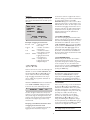
3.4.3 BATTERY STATUS
This function displays the current charge of the
battery.The number is an indication of the
remaining capacity. "STATUS FULL"
(voltage > 540) means that the meter has the
capacity to make over 2300 measurements.
"STATUS HALF" (voltage 450 to 500) means
that about 150 measurements can still be
made.The meter needs a minimum voltage in
order to be able to make a measurement;
"STATUS HALF" therefore does not mean that
WC
78%
v/v
EC
3.6
MS CM
T
19,8
ºC
Slab type 124
Measurement ready
5
the meter can make half the number of measurements as it can with fully charged batteries. "STATUS LOW" means that you should
charge the batteries. A few individual measurements can still be made, but for multimeasurements and logging measurements, the batteries
should preferably display "STATUS FULL".
2.
3.
Attention:
For logging measurements and more than one
multimeasurement, we recommend to charge the
batteries beforehand.The measurements already
carried out, remain stored in the memory when the
batteries run empty.
4.
5.
3.4.4 MULTIMEASURE
(See Quick Guide)
With this function, you start making multimeasurements.You can make a pre-selected number
of measurements per irrigation zone or block.
These measurements are saved.With the function STATISTICS, you can calculate the average
value (WC, EC, and T) and standard deviation
for the block that has been measured.When
carrying out multimeasurements, you can use
the STATISTICS function to obtain a direct display of the average value and standard deviation
per block measured. In addition, you can use the
graphics programme on the PC to import these
measured values per block measured into an
Excel spreadsheet.
The menu will then appear in the screen;
see subsection 3.4.
Select "START MULTIMEASUREMENTS"
with the cursor and confirm the selection
by pressing the MENU key. Next, choose
the size of the block.
With the and keys, you can modify
the size of the block.
Confirm your choice with the MENU key.
The water content meter will indicate the
maximum number of blocks that can be
measured.
You start the first measurements by pressing the START key.The meter will then display the following text on the screen:
WC
EC
T
SLABTYPE
78 %
3,6
19,8ºC
1
v/v
MS CM
(blinking)
READY – SAVE?
= Yes
= No
6. If you press the key, the measurement
will be saved.
7. If you don’t want to save the measurement,
then press .
8. To start the next measurement, press the
START key again.You can repeat this procedure until you want to stop the multimeasurements or until the maximum number
of 250 measurements has been reached.
9. Before and after every measurement that is
saved, the number of measurements and
the block are shown on the screen.
10. At any time during or after the blocks of
multimeasurements, you can, by pressing
the MENU key, evaluate the results.With
the help of the STATISTICS function, the
measurements done until then are evaluated, after which you can continue with the
same series of multimeasurements. If various types of slabs are being measured in
the same greenhouse, then the slab code
can only be changed prior to starting the
first measurement in each new block.
11. It is only possible to change the slab type
before commencing the first measurement
of each new block.
3.4.4.1 START MULTIMEASUREMENTS
You select the number of measurements per
block beforehand. After this number has been
confirmed, the water content meter will automatically be set to begin with the multimeasurements.When doing multimeasurements, you can
store a maximum of 250 measurements.This
means 250 measurements in one block or
1 measurement in each of 250 blocks.The
default setting of the meter is for 25 measurements in 10 blocks.
1. To start the multimeasurements, press the
MENU key once.The following text will
then appear on the screen of the water
content meter:
GRODAN
WATER
CONTENT
METER
6
Attention:
The WCM-control meter saves the multimeasurements in the memory until they are manually
erased. In this manner, it is possible to transfer
these measurements later to the PC (see Chapter
4.5,Transferring data to computer).Try to make
sure, when conducting a measurement session in
the logging measurement or multimeasurements
mode, that the memory is emptied at the
beginning. If the logging function is in use, it is not
possible to do multimeasurements.
Attention:
During logging measurements, check that the clock
is correctly set (see 3.4.9 CLOCK).
Capacity of logging memory
With this function, the meter can carry out a
maximum of 2300 measurements.These measurements are stored in the memory with the
date and time included. In order to achieve
this, you must start logging with an empty
memory ( i.e. the old measurements are not
saved).Answer the questions "MEMORY NOT
EMPTY" and "CLEAR MEMORY" with Yes .
If you want to save the old series of measurements, answer this question with No .
3.4.4.2 STOP MULTIMEASUREMENTS
You can turn off the multimeasurement
function by selecting:
1) QUICK OFF in the menu screen;
2) STOP MULTIMEASUREMENTS
in the menu screen.
In order to stop, answer the question MULTIMEASUREMENT OFF with the arrow for
yes. By activating this function, however, you
delete all multimeasurements in the memory.
If you want to continue with the multimeasurements, select the arrow for no.
However, when the memory for logging
measurements is full, the older measurements
will be overwritten by the new measurements.
Take this into account when selecting the
measurement period and measurement
frequency of the water content meter.
Attention:
If measurements are done every minute over a
period of three days (3 x 24 x 60 = 4320
measurements), only the last 2300 measurements
will be saved. In such case it is best to adjust the
measuring frequency or the measuring period.
3.4.5 STATISTICS
If you use the STATISTICS function, an
overview of the saved multimeasurements
performed until then will appear on the
screen. Using this menu function, you can also
evaluate the interim results during or after the
multimeasurements.The results of one block
are displayed per screen.The average value and
the standard deviation for WC, EC and T are
calculated. By pressing the and keys, you
can browse through the various blocks that
have been measured.
Manually setting the starting time for a series
of logging measurements, date and time:
Start logging
You set the time and date of the first measurement in the same manner as you set the clock
(see 3.4.7 CLOCK).You can postpone the first
measurement for a maximum of one month
and a minimum of three minutes. After you set
the starting time, you must set the measuring
frequency (interval).The interval can be set to
1, 2, 3, 5, 10, 15, 20, 30, 45 and 59 minutes.
After you set the proper interval using and
, you must confirm this with the MENU key.
Next, you set the number of days to be measured in the same manner, and confirm this
with the MENU key.The screen will then show
the number of measurements to be carried
out with the settings selected. During the
measuring period, after the meter has carried
out the number of measurements set, it will
automatically stop logging and shut down.
Attention:
In order to obtain statistically reliable average
values, try to carry out 25 measurements per
measurement block.
3.4.6 START LOGGING
(See also Quick Guide)
By pressing MENU, you can activate the LOGGING function (unless the LOGGING function
is already active).With this function, you can
carry out measurements during a specific time
period and with a measurement frequency
selected beforehand.With the help of the
CDROM included and the infrared cable, you
can later transfer these measurements to the
PC in the form of a graphic or a list of data.
7
Attention:
The first measurement must begin a minimum of
three minutes later than the time at which you set
the meter.
BAT. STAT
LOGGED
LEFT
STARTED
It can later be turned on again. If the meter is
turned on during a period when measurements
are being logged, then the same LOG
OVERVIEW will appear on the screen as when
logging measurements are started. Please note,
however, that the meter can then only be used
in manual mode; logging measurements can no
longer be made.You can again activate logging
measurement mode only after you turn off
manual measurement mode (individual or
multimeasurements).
HALF
48
2252
142225
160402
(blinking)
START LOGGING
= YES
= NO
3.4.7 STOP LOGGING
You can interrupt logging measurements when
turning on the meter by pressing the MENU key
twice.The text "MENU" appears on the screen,
and with the "arrow " the cursor moves to
"STOP LOGGING".After you press the MENU
key, the questions "LOGGING OFF" appears. If
you answer with "YES" (), logging mode is
stopped.The meter will also stop logging once
the number of measurements set beforehand
has been carried out.The measurements remain
stored in the memory.
Example of logging measurement:
Bat. stat: half
= battery status (full,
half or low)
Logged: 48
= number of measurements logged
Left:
2252
= number of measurements still to be logged
Started: 142225 = starting time for
logging measurements
in hours/min./sec.
60402 = starting date for
logging measurements
in day/month/year
3.4.8 COMMUNICATE
With the help of this function, the measurements logged by the hand meter can be
exported to the graphics software programme
on the computer.To do so, the hand meter
must be turned on and the "COMMUNICATE"
function must be activated in the MENU by
pressing the MENU key.
“START LOGGING”
“= YES” “= NO”
At the bottom of the screen, the following text
will blink on and off "START LOGGING" alternately with "YES" () and" NO" (). If you
choose "YES", the meter will automatically
begin in logging measurement mode. If you
choose "NO", the programme will return to
the basic menu.
Attention:
The hand meter must be turned on and set to
menu function "COMMUNICATE" in order to
export the measurements logged to the graphics
programme on the computer. Communication is
not possible if MULTIMEASURE has been started.
3.4.9 CLOCK
In the screen, you can go to the clock function
by using the key. By pressing MENU, you
activate the clock function.This is not possible
in logging measurement mode.With this function, you can display the date (year, month, day)
presently set as well as the time (hours,
minutes, sec.). If desired, you can change
these.You can change the time by pressing
START. Using the and keys, you can
change the blinking time displayed.To change
the next parameter, press MENU. After you get
to the year and again press MENU, you will be
returned to the original menu overview.
When the LOGGING function is activated, the
text "START LOGGING" will appear at the
bottom of the screen, followed by the line:
091246
0101
12
The first six figures indicate the time (hours,
minutes, sec.); the next four figures indicate the
date (month, day); the last figures indicate the
number of the measurement made (maximum
2300).These last figures appear after every
measurement.
Carrying out multimeasurements when
in logging measurement mode
In order to carry out multimeasurements, the
logging function must first be stopped.
Attention:
Take daylight saving time into account
8
3.4.10 LANGUAGE
You can choose any one of several different
languages.The languages available are Dutch,
English, German, French, Danish, Spanish, Italian,
Polish and Russian. All menu functions are
displayed on screen in the language selected.
Confirm the language selected with the MENU
key.
4.3 Installing software
By placing the CD-ROM in the CD-ROM
player, you automatically start the installation of
the "GRODAN WCM control" software.The
software installation can also be started
manually by clicking the "SETUP.EXE" file of the
CDROM.The "GRODAN WCM Logging" software will then be automatically installed on
your PC (C:\program files\grodan\wcm graphic\
WCMcontrol.exe). Make sure that you fill in
the user information so that installation can
take place. Shortcut keys will be placed on the
desktop and in the start menu for starting up
the GRODAN WCM Logging function.
You can remove the software from the system
via START > SETTINGS > CONTROL PANEL
> add/remove programs. After selecting the
GRODAN WCM graphic (=Logging) software,
click "Add/Remove".
3.4.11 QUICK OFF
With this function, you turn the meter off. If
you choose this option from the menu while
the logging function is still active, logging is
continued. If you choose this option while
making individual measurements, the meter will
shut down after one minute. During multimeasurements or if the statistics function is active,
this will take 30 minutes. If any of the other
menu functions are activated, the meter will
shut down after two minutes.
Attention:
When there is no free COM (serial) port available
on the PC, it is also possible to connect the IR sensor to a free USB port. However, this necessitates
the purchase of a universal USB to serial cable and
the corresponding software.These are available
from standard computer/electronics shops. A “free”
serial port can then be chosen (usually COM 5) by
clicking on the “system” icon on the task bar in the
WCM Control graphs programme and then selecting "configuration".
4. PC instructions
4.1 System requirements
The PC used must comply with the following
system requirements:
- A COM port that is available and working;
make sure that no other peripherals - such as
electronic agenda, Revo or I-pacq - automatically claim this port.These programs must be
closed down when reading out the water
content meter.
- 2.5 MB of free space on the hard disk
- 16 MB of internal memory
The operating system required is Windows 95
or higher.
In the event that there is no free COM (serial)
port available on the PC, it is also possible to
connect the IR sensor to a free USB port.
However, this necessitates the purchase of a
universal USB to serial cable and the corresponding software (cost: approx. € 40).These
are available from standard computer/electronics shops (more information on digiconnect.nl).
A “free” serial port can then be chosen (usually COM 5) by clicking on the “system” icon on
the task bar in the WCM Control graphs programme and then selecting "configuration".
4.2 PC
The infrared eye included is meant to be connected to a free COM port on the computer
(COM 1 or 2). Make sure that the port is
properly configured on the PC.When transmitting data, the infrared eye on the computer
should point towards the infrared eye on the
hand meter.The infrared eye (dark red rectangle) is located on the left side of the hand
meter opposite the screen. In order to work
properly, the distance between both infrared
eyes should be between 2 and 20 cm (The IR
eye can also be connected via the USB port, as
long as you use a USB-RS232-interface cable
for doing so).When measurement data is being
transmitted, the "COMMUNICATE" option in
the MENU of the hand meter should be activated.
4.4 Software options
With the GRODAN WCM control software,
you can export the measurements logged by
the meter to the computer, display them in a
graphic, or, if you wish, export them to an
Excel file or e-mail them. In addition, individual
multimeasurements can also be exported into
an (Excel) table.
9
4.5 Transferring data to computer
“STATUS SEARCH”:
The water content meter will try to contact
the computer. Once contact is established,
”hand meter found” appears on screen. If the
blue bar on the computer screen is at its end,
and the hand meter still displays STATUS
SEARCH, make sure that the infrared eye on
the computer is pointing towards the infrared
eye of the hand meter, adjust the distance
between both eyes and again click the icon
in the GRODAN WCM Logging
programme or on FILE > IMPORT > HANDMETER. As soon as the counter next to
STATUS DATA on the screen of the meter is
running, the measurement data are transmitted
and imported into a standard graphic with the
GRAS.exe programme.
Logged measurements
If you wish to export the logged measurements from the hand meter to the computer,
then first use the shortcut key on the desktop
or the shortcut key in the start menu to start
the GRODAN WCM Logging programme.Via
START > SETTINGS > CONTROL PANEL >
SYSTEM > COM PORT, you can select which
COM port you want to use (make sure that all
other programmes using this COM port are
not active, and check whether any other
peripherals are claiming this port; otherwise
you will not be able to open the COM port).
In order to import data from the hand meter,
click FILE > IMPORT > HANDMETER or click
the icon
. Before doing so, the COMMUNICATE function in the MENU of the hand
meter must be activated. In addition, the
infrared eye of the computer must be pointed
towards the infrared eye of the hand meter,
and the distance between both eyes should be
approximately 2 to 20 cm.The COMMUNICATE function in the hand meter must be
activated before the blue bar displayed on the
bottom of the screen for "IMPORTING
MEASUREMENTS DATA" has been completely
filled.
If data import is not successful, the text
"COMMUNICATION ERROR" will appear on
the screen.This can be due to one of the following reasons:
- the meter is not turned on;
- the meter is not set to "COMMUNICATE" in
the MENU;
- the infrared connection is not working properly; the distance between the infrared eyes
is too small or too large.
Transfer of multimeasurements
The transfer of the multimeasurements takes
place in the same manner as the transfer of
logged data from the WCM-control to the PC
(see paragraph above).The data are displayed,
per measurement, in columns in the graph (in
the now empty graph).The data can also be
sent by e-mail or exported to Excel for further
processing.
4.6 Screen management
Once the logged data are imported from the
meter, they are, by default, displayed in the form
of a graph. Beneath this graph, a table is displayed containing the numerical values per
measurement.With the help of IMAGE >
DIVIDE, you can move the graph upwards and
view it. In addition, you can also delete individual measurements by selecting a measurement
with the cursor and pressing the DELETE key.
This modification is then also implemented in
the graph.
If all the conditions have been complied with,
again click FILE > IMPORT > HANDMETER or
click the icon
.
Saving measurements
You can save measurements via FILE > SAVE or
via SAVE AS or by clicking the floppy icon in
the menu bar. If you want to save various
measurement data files, we suggest creating a
separate folder for that purpose and giving the
measurement files different names. By default,
the data files are giving names consisting of the
measurement date (year, month, day) of the
first measurement in the file.You can change
the name.
If the COMMUNICATE function on the hand
meter is activated, the number of measurements saved ("LOGGED:") and the status of
the meter will be displayed on the meter
screen, for example:
COMMUNICATION
LOGGED
416
STATUS
SEARCH
10
4.7 Printing graphics
You can print graphs by clicking the print icon
in the menu bar or by clicking IMAGE > PRINT.
You can preview a print sample via IMAGE >
PRINT SAMPLE.You can modify the print settings via IMAGE > PRINT SETTINGS.The print
function determines beforehand the area that
will be printed.The graph to be printed is sized
so that it will fit into the area to be printed. It’s
best to print graphs using the A4 and landscape
settings, as the ratio between length and width
is based on these settings.
Exporting to EXCEL
You can export the (saved) numerical values
into Excel by clicking FILE > EXPORT TO
EXCEL.After you export the data, the Excel file
can be found in the same folder as the original
file. In order to further process the data in
Excel, you must take several actions to ensure
that each measurement (date, time, measured
values for WC, EC and T) is placed in its own
cell.The new file into which you have exported
the data has the same name as the original file
but with the extension .CSV. The new file
contains the exported measurement data in the
‘Comma Separated Value’ format, which can be
read by Excel. If you double-click the CSV file, it
will automatically be opened in Excel. Of
course, you can also start Excel manually, and
then open the relevant CSV file using the menu
in Excel.When Excel opens the CSV file, it automatically places all the data in only one column
(column A). In order to place the data in several
columns, you first select column A by clicking
the A above the column.The column then
becomes ‘blue’.Then from the DATA menu,
select TEXT TO COLUMNS. A wizard will then
appear which will help you to distribute the
measurement data over several columns. In this
wizard, you should choose the comma as
separation symbol. After you make use of the
wizard, the data will be distributed over several
columns.You can then save the file as a normal
Excel spreadsheet via FILE > SAVE AS.
Scale of measurements in graphic
Using IMAGE > SCALE, you can set the minimum and maximum values that can be displayed in the graph separately for WC, EC and T.
4.8 E-mail function
In the following, it is assumed that an Outlook
e-mail software programme is installed and
available on the computer. If necessary, other
email programmes that support the Microsoft
Mail protocol can also be used as long as they
are available on the PC. If a series of measurements has been imported using the GRODAN
PC software, you can mail these measurements
via IMAGE > SEND AS EMAIL. E-MAIL is not
available (light grey colour) if there is no active
e-mail software programme available on the
PC. After you select the SEND AS E-MAIL
option, an empty e-mail message window is
automatically opened with the measurement
data file as an attachment.You only need to fill
in the name of the addressee in the TO field.
The relevant file with measurement data is
included in this e-mail message as an attachment.The person receiving this e-mail can open
the file only if he has the graphics programme
of the logging meter. Otherwise, the file should
be sent as an Excel file, so that the addressee
can open it and work with it in Excel.
Removing graphic lines
The check marks next to IMAGE > WC-graph,
IMAGE > EC-graph and IMAGE > T-graph
determine which lines on the graph will be
visible or not.
Overview graphic for 1, 3 and 7 days
On the menu bar, you’ll find options for
1 (1 day), 3 (3 days) and 7 (7 days). If you click
one day 1, the data over 24 hours will be
displayed in a graph from 6 a.m. until 6 a.m.
If you click 3, the data over 72 hours will be
displayed in the graph, and if you click 7, then
168 hours will be displayed. If more days have
been measured than the 1, 3 or 7 that was
selected, then you can use the arrows in the
menu bar to go back and forth , per day.
11
5. Maintenance
5.4 WCM models
Older types of sensors (from before
31 December 2003 - check the series number
on the back side of the meter beginning with
2003 and lower) will not work with the newer
type of WCM-control or vice versa. If they are
nevertheless connected, the system will not
function, but the equipment will not suffer any
damage.
The voltage adapters are identical, and are
therefore interchangeable as long as the plug
fits.
5.1 General
Note:
It is best to disinfect the sensor pins before and
after every series of measurements. But be careful
with using aggressive agents.
The water content meter does not require
much maintenance. If the screen or the data
cable becomes dirty, clean it with a moist
cloth. Never use an aggressive cleanser. If the
meter is not working properly, it can be initialized again by charging the meter until a normal
text appears on the screen.
6. Specifications
6.1 Parameters
The WCM-control meter measures a volume
equal to about 10 x 3.5 x 7.5 cm3 (length x
width x height).
5.2 Batteries
The lifetime of rechargeable batteries is limited. Under normal conditions, the batteries can
be recharged 1000 times. If the capacity of the
batteries becomes insufficient, you can replace
them with nickel metal hydride batteries of the
same size and capacity (1.2 V - 1800 Ah). If one
of the batteries is defective, the adapter can
detect this, and the following message will
appear on the screen:
In this volume, the following parameters are
determined:
- The water content (WC) in volume
percent (% v/v)
- The electrical conductivity (EC) in mS/cm,
calibrated via international standard.
- The water content meter measures the
amount of nutrients dissolved in the
substrate (by measuring the EC).The
measured value will be equal to the value
determined with the help of samples taken
from the slab.
- The temperature of the slab (T)
The water content and the electrical
conductivity measured are both corrected
for temperature.
ERROR 2
In that case, check the contacts of the adapter,
and check the contacts and the type of the
batteries.Try recharging again. If necessary, the
water content meter can also work on normal
non-rechargeable batteries. In that case, be
sure NOT to turn on the adapter, as this can
result in irreparable damage.When replacing
the batteries, replace all four batteries at the
same time.
6.2 Conditions
The water content meter will take correct
measurements if the substrate complies with
the following requirements:
See table 1 next page
- The sensor pins of the meter are dry and
clean when starting the measurement.
5.3 Calibration
The meter does not need to be calibrated. If
you have any doubts, you can check the calibration by holding the pins in the air or under
water.The meter should then read 0% and
100% respectively (with a margin of 5%). If you
get incorrect measurements, please
contact your supplier.
If the screen becomes too warm, it can
become dark, making it impossible to take a
reading.This effect is reversed once the
temperature of the screen returns to normal.
6.3 Voltage adapter
The meter is supplied with a voltage adapter
with a 4 mm jack plug as connector.
Input: 100 - 240 VAC / 47 - 63 Hz / 400 mA
Output: 9 VDC / 1.5 A
12
6.4 Range and accuracy when measuring
in stone wool
see table 1 next page
This does not apply to the voltagae adapter if
used with a system other than the water
content meter described above.
6.5 CE certificate
The water content meter is CE certified, which
means that the meter has been tested and
approved in accordance with the following EMC
guidelines:
EN61000-6-4 (2001)
EN61000-6-2 (2001)*
EN61000-3-2 (1995) + A1 (1998) + A2 (1998)
EN61000-3-3 (1995)
Attention:
The presence of transmitters in the vicinity that
work with radio frequencies can influence the operation of the water content meter.
* = Due to the operating principle of the sensor, deviations are possible
in measurements at certain frequencies.The size of the deviation and the
relevant frequencies are described in the laboratory documents
03C01265EUT1. If requested, Grodan can send you these documents.
Table 1: Specifications
Parameter
WG (%v/v)
EC (mS/cm)
T (°C)
Measuring conditions
Measurement range
Accuracy
Resolution*
Min
Max
Min
Max
Min
Max
Min
Max
25%
95%
0%
100%
2.5%
5.0%
0.1%
0.2%
0
10
0
20
0.1
0.5
0.01
0.02
10
40
0
50
0.5
1
0.1
0.1
* The resolution indicates the smallest interval which can be measured using the meter.
Attention:
The EC measured using the WCM is calibrated via the international standard at 20 °C. Globally, most
EC meters are also calibrated at 20 °C. However, in the Netherlands it is more usual to calibrate EC meters
at 25 °C, which results in a measurement 10% higher than when taken with a meter calibrated at 20 °C.
Therefore, if one compares the EC measured by the WCM with a sample taken from the slab with a syringe and
measured with a conventional EC meter, the latter value will be about 10% higher.
Note: The specifications apply when taking measurements in water containing nutrients. Deviations may occur
in substrates depending on the type of substrate and the salts present.
13
7. Error-codes
ERROR CODE
1
2
3
4
5
6
7
DISCRIPTION
EPROM does not work correctly
check connector/plug connection
contact your supplier
Adapter or battery error
check the contacts on the adapter
use the adapter supplied
check the contacts and the type of the batteries
try charging again
There is no sensor connected or the sensor does not work correctly
contact your supplier
Insufficient battery capacity
charge the batteries again
replace batteries by new ones
RAM does not work correctly
try a second time
contact your supplier
Incorrect adapter
use the adapter supplied
Communication does not work correctly
try a second time
meter is not turned on
meter is not set to ‘communicate’ in menu screen
malfunction in infrared connection
distance between infrared eyes is too small or too large
14
All the information and recommendations provided in this document have been compiled with the greatest possible care, but we cannot accept liability for any errors involved: November 2006.
8. Guarantee: terms and
conditions
GRODAN guarantees that the products
delivered have been manufactured with the
best materials. If nevertheless there are any
defects in the products delivered as a result of
manufacturing or material faults, then
GRODAN will decide to either repair the
defects, or to have them repaired, to deliver
the necessary parts for the reparation, to
completely replace the goods, or to refund the
value of the meter but never an amount larger
than the value of the meter.This guarantee is
valid for a period of 12 months after delivery.
Meters older than 5 years can no longer be
repaired due to the (lack of) availability and
cost of parts and the technical improvements
incorporated into new meters.With regards to
guarantee and/or complaints related to parts
and materials, GRODAN will rely on the liability
of the supplier of the parts and/or materials
concerned. GRODAN will not accept any liability for other obligations, such as compensation
for losses due to the cancellation of the
contract. Any complaints under this guarantee
should be forwarded in writing to GRODAN
within a period of eight days after the damage
has occurred. If the customer does not
comply with, or does not comply with in a
timely fashion, the conditions of the warranty
of GRODAN or a related contract, then
GRODAN will not be required to fulfil any
guarantee or payment as described regarding
to the contract. GRODAN reserves all its
rights in these matters. Nothing from this
publication may be copied or brought into the
public domain through printing, photocopying,
microfilm or in any other fashion without
written prior permission from GRODAN.
This also applies to the drawings and diagrams
concerned.
More information
Grodan BV
The Netherlands
Tel.: +31 475 353 020
Fax: +31 475 353 716
E-mail: [email protected]
www.grodan.com
GRODAN reserves the right to modify a part or
parts of the equipment at any time it chooses
without informing the customer beforehand or
at the time.The contents of this publication
may be changed without prior notice.
For further information regarding settings,
maintenance and repairs, we ask you to
contact Grodan Customer Service.
Although this publication has been carefully
written, GRODAN cannot be held liable for
any errors or mistakes in this publication and
any of their consequences.
15