1
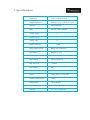
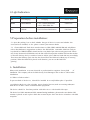
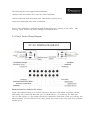
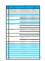
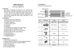
GPSVehicle Tracker
User Manual
(Version 2.0)
Contents
1. Accessories (Included in the Box) ................................................................................... 3
2. Features ........................................................................................................................ 4
3. Specifications ................................................................................................................ 5
4. Light Indication ............................................................................................................. 6
5. Preparation before installation: .................................................................................... 6
6. Installation ................................................................................................................... 6
7. Basic Programming of GPS Tracker ................................................................................ 8
8. Programming the GPS Tracker to connect with the Web Software ............................... 11
9. Troubleshooting .......................................................................................................... 12
1. Accessories (Included in the Box)
·
·
·
·
·
·
·
·
·
GPSTracker
Power Cable (16 Pins)
Relay
Microphone
SOS Button
Sim Tray
Shock Sensor*
GPS Antenna
GSM Antenna
* This Component is optional and available with selective models only
Please read this manual carefully before attempting installation and onlineactivation. Pictures are for
indication and illustration purposes only. Any miss-happening with the Car or car passengers, our
company will not be liable for any loss caused due to any reason .
2. Features
·
Live Tracking of the vehicle via Internet Software and Mobile
·
Control power supply of the car
·
Lock/Unlock the Doors**
·
Over Speed reporting
·
Geo fencing reporting
·
Movement alert
·
Accident/Shock alert*
·
SOS Hi-jack button for emergency
·
Voice monitor of the car
·
Power Cut Alarm when the power supply is disconnected/Voided
·
Built-in Battery back up
·
Air Condition On/off status detection
·
Engine On/Off status detection
·
Lights On/Off status detection
·
Door Open/Close Detection
·
Temperature sensor*
·
Fuel sensor*
* Refers to optional functions in selective models
** Refers to function available in selective vehicles/Car models only, according to car specification
3. Specifications
Dimension
7.5 L X 7.2 W X 2.2 H cm
Weight (with Box)
0.650 g ( 17 L X 11 W X 7.5 H ) cm
Network
GSM-GPRS-GPS
Band
850-900-1800-1900 MHz
Digital inputs
6
Digital outputs
2
Analog input
2
Internal Memory
2 MB
Temperature Sensor
Range:-40~125 Degree
Fuel Sensor
Range:0.1V~12V
GPSChipSet
SiRF III
GSM Module
Simiens/SIMCOM
GPS Sensitivity
-159dBm
GPSaccuracy
5M
Work Voltage
DC9V-30V
Battery
Chargeable 3.7V/750 mAh
Standby Work Current
<30MA
StorageTemp.
-40~85 Degree
Operational Temp.
-20 to 70 Degree
Humidity
5%~ -95% Condensing
4. Light Indication
LEDColor
Stable
Blinking
RED
Not Charging
GREEN
GSM-GPRSOK
1 Sec-1 Blink: Initilization
3 Sec-1 Blink: GPRS Pro.
GSM Error!
Blue
GPSOK
GPS Not Found-Initilization
GPS Error!
Charging
No Power
Power Error!
5.Preparation before installation:
5.1 Open the packing box to check whether the type of device is correct and whether the
accessories are included, or else please contact your nearest dealer
5.2 Choose SIM card: Each device needs to insert a GSM, GPRS enabled SIM card only.Please
refer to the distributors suggestions to choose the SIM card.Do remember GSM sim card you
buy should be GPRS Enabled.It should not have any kind of pin code/security password. If there
may be any Password of GSM Sim card, the Sim card will not perform with the GPS tracker modem
on near the Sim tray slot by a needle or a narrow Object, place SIM card in the Sim tray accordingly.
Then insert the SIM tray again into the slot (do not insert the SIM card without tray or in wrong
position). When the SIM card is placed in rite direction, you can see the Red LED
glowing.
6. Installation
Please refer installation to an auto electrical or professional car engineer for any kind
of
installation. The company will not be liable for any Loss/Damage to the car due to GPS tracker
installation
6.1 Where to fit the tracker?
To prevent theft of the device, it should be installed in covertly/hidden place if possible.
Avoid placing the device close to higher power electrical devices,such as reversing radar,antitheft device or other vehicle communication equipment.
The device should be fixed into position with cable ties or wide double-side tape.
The device has GSM antenna and GPS antenna.During installation, please make sure that the GPS
Antenna is placed at such a place which has no metal object above the device to interfere with GPS
reception.
The following places are suggested for installation:
-Shelter in the decorated board below the front windshield;
-Shelter around the front instrument panel (non-metallic material face);
-In the decorated board below back windshields
Notice: if the windshield is pasted with metal thermal-protective coating, It may affect
receiving signal. In this case, please change the installation place.
the
6.2 Vehicle Tracker Wiring Diagram
ST 101 WIRING DIAGRAM
Instructions to connect the wiring :
Power: The standard voltage is 9V-24V DC. Please use the power cable which is provided with the
GPS tracker only. Connect the Red cable (No. 16) with the direct (+) 12 V of the car. The black wire
(No. 8) is the negative (-). The negative should be connected to earth alone of the car or link any iron
during installing. Do not connect it to any other ground wire which is also being used for any another
function of car.
ACC/Ignition: The green wire (No. 14) should be connected to the ACC switch of the vehicle. Please
make sure to connect the ACC of the car, as many reports in the software are based on ACC/Ignition
Light On/Off Detection: The Purple wire (No. 15) should be connected with the Head Lamp Power
On/Off wire to detect the current when the light is On/Off. When the current flows in the wire, it
will state as Light is ON.
Fuel Sensor:The Yellow-Black wire (No. 11) of the tracker should be connected with the Digital Output
of the Fuel Gauge in the car. Every car has a gauge in the fuel tank. This fuel gauge has 3 wires as (+)
Positive; (-) Negative; Digital Output wire. Kindly connect No. 11 wire with the digital Output wire
only.
Air conditioner On/Off Detection: The Orange wire (No.3) should be connected with the Air
Conditioner Power On/Off wire to detect the Status when the Air Conditioner is On/Off. When the
current flows in the wire, it will state as Air Conditioner is ON.
Shock Sensor: Shock sensor have 3 wires. Black wire should be connected with the Black wire (No.
12) of the tracker, Red wire should be connected with the (+) 12 V of the car, Gray wire should be
connect with Gray wire (No. 2) of the tracker. Also the Shock sensor range should be adjusted
manually to the maximum. This sensor should be screwed nicely with the body of the car ,so that
you get the accurate results. It can be fixed near the Accelerator Pedals of the car, hidden and
screwed on the metal body of the car.
Door Status Detection: The Brown wire (No.13) should be connected with the Door Open/Close
I status main wire, which has the (-) voltage, when the doors are opened. When the doors are closed,
the Voltage will be 0
Electricity cut off: The Ignition wire of the car should cut and connect both ends of the wire with the
relay No. 87 and 30. The No. 85 should be connected to vehicle positive power (+12V).The No. 86
should be connected to the device white wire (No. 4). Please refer to wiring diagram
Door Lock**: Door Lock/Unlock Circuit wire of the car s hould cut and connect both ends of the wire
with the relay No. 87 and 30. The No. 85 should be connected to vehicle positive power (+12V).The
No. 86 should be connected to the device yellow wire (No. 5). Please refer to wiring diagram
** This function is Available in selected vehicles only, depending upon Car Manufacturers
SOS Button: Connect the SOS button blue wire with the blue wire (No. 6) and black wire with the
tracker black wire (No. 7)
Temperature Sensor: The wire (No. 9) (No. 10) will be having a temperature sensor pre-installed.
Just place and fix it nicely at the place you need to detect the Temperature.
7.0BasicProgramming ofGPS Tracker
7.1 Add authorized number as a Admin
This command is generally used to bind the tracker with a particular Mobile number. After this
command the tracker will only revert to that particular Mobile number. Also 1 Admin mobile can
make another 4 Sub-Admin by sending the SMS from Admin mobile only.Send SMS <admin123456
1588938832> . <Admin> as instruction,<123456> as password, <15889388832> as authorized number. It
will reply <admin ok!>
7.2 Delete authorized admin number
Send SMS <noadmin123456 15889388832>. <noadmin> as instruction, <123456> as password,
<15889388832> as deleted number. It will reply <noadmin ok!>
7.3 Change the Password
Send SMS: <password + old password + space + new password>to change the password. For example:
Send SMS <password123456 138138>.< Password> as instruction,<123456>as old password, <138138>
as new password. Password must be six digits. Tracker default password is 123456. If you forget your
password, you can resume the default password 123456.Send <resumepassword> to the tracker, the
tracker will resume the default password. If there is no authorized numbers, all numbers can resume
initial password. If there is already authorized numbers, only the authorized numbers can resume
default password.
7.4 Open/Close Door
Send SMS <closedoor123456> to lock the doors. For example send SMS:<closedoor123456>
<closedoor> as instruction, <123456> as password.
To open the door again, send SMS <opendoor123456> to the unit. For example, send SMS
<opendoor123456> to the tracker.< opendoor> as instruction,<123456> as the password.
7.5 Control Circuit Electricity
Send SMS <stopelec123456> to control circuit. For example send SMS:<stopelec123456>.<stopoil> as
instructions,<123456> as the password.
To supply the circuit again, send SMS <supplyelec123456> to the unit. For example, send SMS
<Supplyelec123456> to the tracker.<Supplyelec> as instruction, <123456> as password.
7.6 Monitor mode-There are three modes for monitor.
1) All Monitor Modes: Send SMS <AllMonitor> to the unit, the unit will return to this mode. In this
mode, any number can monitor this unit. For Ex.: If you call the tracker, the call will be picked up and
you can hear the Microphone voice in the car
2) Restrict Monitor Mode: Send SMS <RestrictMonitor> to the unit, the unit will return to this
mode. In this mode, authorized number can monitor this unit.
3) Close Monitor Mode: Send SMS <CloseMonitor> to the unit, the unit will return to this mode. In this
mode, all numbers can not monitor this unit by SMS, but if they call the tracker, the call will cut
and the Position SMS will come back
<123456> as password.When ever the car moves more than 80 km/hr speed. The customer will get
an SMS Alert.Cancel: Send SMS <nospeed+password> to deactivate the over speed alert.
7.6 Movement alert
Set up: The user can send SMS <Move + password>to the unit, then the unit will reply<move ok!> In
case of there is a movement of car, it will send SMS<Move> along with a Geo-info to the number.For
example, send SMS<Move123456> to the unit.<Move> as instructions,<123456> password.
Cancel: Send SMS <nomove+password> to deactivate the movement alert.
7.7 Over speed alert
Set up: Send SMS <speed+password+space+080>to the unit (Suppose we set the speed is 80km/h). For
example, send SMS <speed123456 080>.<Speed> as instruction,<80> as limit speed, and <123456> as
password.When ever the car moves more than 80 km/hr speed. The customer will get an SMS
Alert.Cancel: Send SMS “ nospeed+password” to deactivate the over speed alert.
7.8 Geo-fence
Set up a geo-fence for the unit to restrict its movements within a district. The unit will send the
message to the authorized numbers when it breaches the restricted area.Set up: The user can Send
SMS<stockade + password + space + MinLatitude, MinLongitude; MaxLatitude, MaxLongitude> to
unit to set the restricted district. In case of breach, it will send SMS <stockade! + geo-info> to the
authorized numbers.For example send SMS <stockade123456 22.548123,114.081234;
22.549123,114.082234>to the unit.Remark: The first latitude & longitude is coordinate of min of the
Geo-fence, while the second latitude & longitude is the coordinate of the max. It will alarm one
time in each setting.Cancel: Send SMS <nostockade + password> to deactivate this function. This
function will be out of effect after the unit moves outside the district.
7.9 Restart the tracker
Send SMS <reboot+password> to the tracker. For example<reboot123456>.The tracker will be
restarted. It will reply <system will reboot...>. This command is given if some majorly new changes
have done.
7.10 Enquiry Positioning
Send SMS <position+password>to the unit, then the unit will send SMS with real-time longitude and
latitude encrypted in the Google map link and the current speed of the car to the cell phone. For
example SMS : <postion123456> and it will reply the Google Co-ordinate
7.11 Set country time zone
For different countries there is different time zone.The user can set their country time zone by
sending the SMS command. The format is <zone + password + space + time zone value> For example,
<zone123456 5.5> is set 5.5 time zone. Time zone value ranges from -12 to 12.After send SMS;
tracker will reply <Set Time Zone OK>.
7.12 SOS alarm
In emergency case, press SOS for 3 sec. to activate SOS alarm. Then the device will send SOS SMS to
specified Admin as: <Help Me!> Note: For using this facility, make sure the Specified number is
added in the Admin list of the tracker. If no Admin number is added, the Tracker will not send SOS
alarm SMS to any mobile number
7.13 Accident/Shock alarm
When ever the Driver is driving the car rashly and the car is suffering with a lot of shocks or a
accident happens. The Tracker will immediately send a SMS alert to the Admin Number
as: <Car Rash Driving!>
8. Programming the GPS Tracker to connect with the Web
Software
The SMS command format should be all in small letters and sent one by one after receiving the
confirmation SMS back from the GPS tracker SIM Card. If the SMS not come back, please check your
command else send the command again.
8.1 Set GPRS /APN Settings in the tracker
For example: When the device goes to Indonesia, and the customer put the Sim card of Indonesian
Telecommunication. So the tracker has to be programmed with the GPRS setting which is of that
particular telecommunication company. Every Company has different APN (Access Point Name). For
searching your telecommunication APN setting please call to the Helpline of that particular
Telecom Company.SMS:< apn123456 cmnet> .Reply Back: setAPN OK
8.2 Modify IP address and port
To send the data to a specific IP of the software, you need to SMS the following command to the tracker
and the tracker will start sending all data to the specified IP.Send SMS <ip+ ip address + PORT
+ Port Address> to the unit. If the platforms IP address and port is 182.18.188.143 and 5001, send
SMS <ip182.18.188.143por5001> to the tracker. It will reply <set IP address and PORT ok> After this,
device will send GPS data to this particular IP and Port only.
8.3 Set Device ID number
In order to identify device on the software platform, it is must to set a unique device ID for every
device. Send SMS <number + tracker ID number> to the tracker. For example
<number13612345678>.We recommend to make the Sim Card number as the device ID
8.4 Set GPRS user name and password (Optional)
Some country has GPRS user name and password for GPRS communication. To activate the GPRS in the
tracker please send the following command: <user + space + GPRS user name + space + GPRS
password>For example:<user 123456 00000>,<user> is command,<123456>is GPRS user
name,<00000>is GPRS password. After send SMS, tracker will reply <Set GPRS User and Password ok>
8.5 GPRS time sending interval (Auto track)
This command is sent to call the data from the tracker after Interval time.
Send SMS <at30sum0> to the unit; it will reply <Auto track set ok> And after every 30 seconds the
data will report to the software platform. The min intervals can be sent is for 10 seconds.
9. Troubleshooting
After installing it in the first time, if device can not get connected with platform server, Please check
the installation of device:
1) Check whether 3 LEDs are functioning accordingly as follow, else refers to the user manual
contents:Red: Blinking£»Green: Stable£»Blue: Stable
2) Check whether SIM card is installed correctly, and have enough balance for the SMS/GPRS
3) Check whether GPS is located, if not, please drive to the open areas for positioning.
If it is offline” status in platform:
Please check the SIM card status:
1) Call the SIM card number of the device to check whether you can get through the Sim card or the
Sim card is powered off
2) Check whether the vehicle is in no GSM area, such as basement.
3) Check whether the Device ID entered in the Platform and the Sim Card number should be same.
To add a Device ID to the Tracker, kindly SMS: number+Sim card mobile number (For Ex SMS:
number15889388843)
If the device’ GSM function is normal, but can not locate for a long time, please check whether the
installation setup of device is correct:
1) Please make sure the GPS antenna is facing up
2) Please make sure there is no electromagnetic wave- absorbent object (metal) above the device,
especially the thermal-protective coating on the windshield, it may affect the GPS reception of the
device
3) If GPS can not receive the signals normally (there is high building around to interfear with GPS
reception), please drive to the open areas for positioning. Generally,it needs 60-80 Sec. to receive
the first coordinates.
If the Tracker was working fine earlier but suddenly all LED lights are powered off:
1) Kindly check the fuse of the tracker which is in the red wire of the power cable
2) Kindly check the wiring. In most of the cases, while installing the tracker, the engineer may leave
some wire loose, due to which the trackers come into Power off mode, after the battery of the tracker
is also low.
3) Please contact customer care or nearest companys authorized service center
NO.
FUNCTION
SMS
REPLY BACK
1.
Add number as Admin
admin123456 15889384493
Admin OK
2.
Delete Admin number
noadmin123456 15889384493
No Admin OK
3.
Change Password
password123456 138138
Ch.Password OK
4.
Resume Password
resume Password
Resume Pass.Ok
5.
Door Control
opendoor123456
Opened OK
closedoor123456
Closed ok
supplyelec123456
Supply Elec OK
stopelec123456
Stop Elec OK
allmonitor123456
Set All Mon. OK
restricmonitor123456
Set Rest.Mon.OK
closemonitor123456
Set Close Mon.OK
6.
7.
8.
9.
10.
Control Circuit
Set Monitor Mode
Movement Alert
OverSpeed Alert
Geo-Fence Alert
move123456
Move OK!
nomove123456
No Move Ok!
speed123456 080
Speed OK!
nospeed123456
No Speed OK
stockade123456 coordinate;
Set GeoFence Ok
coordinate
nostockade123456
No Geo-Fence OK
11.
Reboot tracker
reboot123456
System will rebot
12.
Enquire Position
position123456
Postion Info
13.
Auto Track Interval
at10sum0
Set Auto Track Ok
14.
Set GPRS APN
apn123456 XXXXXX
Set APN Ok
15.
Set GPRS User Name,Pass.
user name,pass
Set GPRS User OK
16.
Set IP and Port Address
ip182.18.161.55port5001
Set Ip Port OK
17.
Set Device ID
number15889384493
Set Number Ok
18.
Set Time Zone
zone123456 5.5
Set Time zone OK
19.
IMEI
imei123456
imei number
Manual Version:20120227
(c) CopyRights by Maping Suryansh tracking Pvt Ltd
www.mapingworld.com