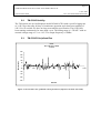
1
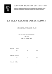
E U R O P E A N S O U T H E R N O B S E R V A T ORY
Organisation Européenne pour des Recherches Astronomiques dans l'Hémisphère Austral
Europäische Organisation für astronomische Forschung in der südlichen Hemisphäre
LA SILLA OBSERVATORY
TIME MACHINE
INSTALLATION AND USER’S MANUAL
Doc. No.: LSO-MMN-ESO-60100-0001
Issue: 2.0
Date: 8-January-2005
Prepared: J. Alonso
Name
Date
Signature
Date
Signature
Approved: G. Andreoni
Name
Released: G. Andreoni
Name
Date
Signature
Page 2
TIME MACHINE INSTALLATION AND USER’S MANUAL
8-Jan- 2005
Doc. LSO-MAN-ESO-60100-0001
Technical Document
CHANGE RECORD
Revision
Date
Section/Paragraph
Remarks
Issue 1.0
Issue 2.0
14/12/2002
08/01/2005
All
Several
First Issue
Page 3
TIME MACHINE INSTALLATION AND USER’S MANUAL
8-Jan- 2005
Doc. LSO-MAN-ESO-60100-0001
Technical Document
INDEX OF CONTENTS
1.
INTRODUCTION .............................................................................................................................4
1.1.
1.2.
1.3.
1.4.
2.
TIME MACHINE OVERVIEW..................................................................................................4
REFERENCE DOCUMENTS.....................................................................................................5
APPLICABLE DOCUMENTS ...................................................................................................6
ACRONYMS & ABBREVIATIONS..........................................................................................6
HARDWARE SETUP .......................................................................................................................7
2.1. TM PHYSICAL PLACEMENT ..........................................................................................................7
2.2. TM POWER REQUIREMENTS .........................................................................................................7
2.3. TM ELECTRICAL AND OPTICAL CONNECTIONS ............................................................................7
2.3.1.
Front Panel..........................................................................................................................7
2.3.2.
Rear Panel ...........................................................................................................................8
3.
SOFTWARE SETUP AND COMMANDS .....................................................................................9
3.1. BOOT PARAMETERS......................................................................................................................9
3.2. COMMANDS ................................................................................................................................10
3.2.1.
Stand_alone_mode............................................................................................................10
3.2.2.
GPS_mode.........................................................................................................................10
3.2.3.
Set_time.............................................................................................................................10
3.2.4.
Set_julian_day ..................................................................................................................11
3.2.5.
Time_offset........................................................................................................................11
4.
OPERATION...................................................................................................................................11
4.1.
4.2.
4.3.
4.4.
4.5.
5.
COLD START...............................................................................................................................11
GPS MODE..................................................................................................................................12
STAND ALONE MODE ..................................................................................................................12
PRECAUTIONS .............................................................................................................................12
REBOOT ......................................................................................................................................13
APPENDIX ......................................................................................................................................13
5.1.
5.2.
5.3.
5.4.
5.5.
LA SILLA TELESCOPES TIME REQUIREMENTS .............................................................................13
TM OCXO STABILITY ...............................................................................................................14
TM OCXO DISCIPLINED RUN ....................................................................................................14
TM OCXO OPEN LOOP RUN ......................................................................................................15
OCXO CONTROL VOLTAGE REFERENCE VALUE........................................................................15
INDEX OF FIGURES
FIGURE 1: TM BLOCK DIAGRAM ..................................................................................................................5
FIGURE 2: TM FRONT PANEL .......................................................................................................................8
FIGURE 3: TM REAR PANEL .........................................................................................................................9
FIGURE 4: TIME REQUIREMENTS TABLE .....................................................................................................13
FIGURE 5: OCXO 18 HRS RUN, OPTIMISED CONTROL PARAMETERS (DEPARTURE FROM THE GPS 1PPS) ...14
FIGURE 6: OCXO 16 HOURS OPEN LOOP RUN (DEPARTURE FROM THE GPS 1PPS).....................................15
Page 4
TIME MACHINE INSTALLATION AND USER’S MANUAL
Technical Document
1.
8-Jan- 2005
Doc. LSO-MAN-ESO-60100-0001
INTRODUCTION
1.1. TIME MACHINE OVERVIEW
The Time Machine (TM) is a clock capable of generating a Time Interface Module
(TIM) signal. The TM has two modes of operation, “GPS” and “Stand alone”, this
makes it very versatile and safe. In “GPS” mode the TM is always disciplining it’s
quartz Oven Controlled Crystal Oscillator (OCXO) and storing the average control
voltage value every 24 hours in it’s battery backed up Complementary Metal Oxide
Semiconductor (CMOS) Random Access Memory (RAM). In “Stand alone” mode the
OCXO is operated using the latest averaged value found in the CMOS RAM.
The core of the TM is built in a Versa Module Europe (VME) module, which operates
controlled by a MVME167 Central Processing Unit (CPU) running the necessary
control and interface software. All the system is housed in a VME crate, which
additionally contains an OCXO unit and a Global Positioning System (GPS) receiver.
Please refer to Figure 1 below for a better visualization.
Basically the TM VME module interacts with three different sub-systems via VME bus
independent lines and with the CPU via the VME bus itself.
The TM VME module interacts with the OCXO from where it receives a 10Mhz signal
and phase compares it with the GPS or external 1 Pulse Per Second (PPS), the resultant
error signal is filtered by a digital Proportional Integral (PI) controller with an
adjustable time constant of several hours and the output is fed to a 20 bit Digital to
Analogue (D/A) converter to obtain the OCXO control voltage. While the GPS_OK
signal is asserted the OCXO control loop remains closed and the control voltage
updated once every 10 seconds, if the GPS_OK signal fail the control voltage is frozen
with an average value. The phase measuring and control voltage resolutions are 25nS
and 10uV respectively.
The TM VME module interacts with the EconoGPS from where it receives three
different signals, a serial string containing the Universal Time Coordinated (UTC)
hours, minutes, seconds and modified Julian day, a 1 Pulse Per Second (PPS) reference
signal and the GPS_OK flag. The UTC information string is manipulated by the
software in the CPU and loaded into the serializing Electrically Programmable Logic
Device (EPLD) using interrupts for synchronisation. Since the TIM signal is a serial 1
Mhz carrier that contains all the UTC information in Pulse Width Modulation (PWM)
encoded format, it is necessary a dedicated hardware for this function. Inside the EPLD
a group of counters, latches, flip-flops, shift registers and gates are responsible for this
time critical task. This EPLD is seen by the microprocessor as a standard peripheral
circuit very much like a standard Universal Synchronous Asynchronous Receiver
Transmitter (USART) normally used for standard RS-232 interfaces.
The TM VME module interacts with the Time Bus Distribution Box (TBDB-TX) ESO
standard module. This is a simple converter from balanced differential to four ST
optical outputs. For further details please refer to [RE5].
Page 5
TIME MACHINE INSTALLATION AND USER’S MANUAL
8-Jan- 2005
Doc. LSO-MAN-ESO-60100-0001
Technical Document
The TM VME module interacts with the VME bus for communication with the
MVME167 CPU.
TIME MACHINE
VME CRATE
TB1
TIM SIGNAL
TBDB-TX
TB2
TB3
TB4
MVME167 CPU
RS-232
TM VME MODULE
LAN
OPTICAL
TIM SIGNAL
OUTPUTS
EXTERNAL 1 PPS
1 PPS
GPS_OK
EconoGPS
SERIAL DATA
ANTENNA
CONTROL VOLTAGE
OCXO
10 Mhz
VME bus
Figure 1: TM Block Diagram
Although the system exploits a GPS both for disciplining the built in high stability
quartz OCXO and obtaining the UTC and modified Julian date, the GPS can be
dropped at any time and operated as a high quality stand alone quartz clock keeping the
latest average control voltage for the OCXO.
As a GPS independent system it is possible, when required, to discipline the oscillator
using any high quality1 PPS source such as a Rubidium or Cesium oscillator to correct
for the long-term drift and aging of the quartz, as well as manually set the UTC,
modified Julian day and increase or decrease the time by +/-999 mS in steps of 1mS.
1.2.
REFERENCE DOCUMENTS
[RE1] La Silla time distribution system requirements. M. Mornhinweg.
[RE2] Time Reference System of the ESO Very Large Telescope Werner R.
Lange, Martin Ravensbergen.
[RE3] Time Reference System of the VLT Martin Ravensbergen, Krister
Wirestrand.
[RE4] GARMIN GPS 25 LP Series Technical Specification
[RE5] VLT Time Reference System TBDB Test Report F. Biancat VLT-TREESO-17300-0848.
Page 6
TIME MACHINE INSTALLATION AND USER’S MANUAL
Technical Document
1.3.
8-Jan- 2005
Doc. LSO-MAN-ESO-60100-0001
APPLICABLE DOCUMENTS
[AP1] Time Reference System, Time Interface Module, Technical Manual M.
Ravensbergen. VLT-MAN-ESO-17300-473
[AP2] VLT Time Reference System Datum Unit Test Report F. Biancat VLTTRE-ESO-17300-0849.
[AP3] La Silla EconoGPS Clock Preliminary Technical Documentation Version
2.0 M. Mornhinweg.
[AP4] Procedure for Calibration of Time Sources LSO-PRO-ESO-60500-0002.
1.4.
GPS
CMOS
RAM
TIM
TM
VME
OCXO
TBDB
TBD
VLT
NTT
EPLD
PPS
D/A
USART
CPU
PWM
UTC
UPS
ACRONYMS & ABBREVIATIONS
Global Positioning System
Complementary Metal Oxide Semiconductor
Random Access Memory
Time Interface Module
Time Machine
Versa Module Europe
Oven Controlled Crystal Oscillator
Time Bus Distribution Box
To Be Defined
Very Large Telescope
New Technology Telescope
Electrically Programmable Logic Device
Pulse Per Second
Digital to Analogue Converter
Universal Synchronous Asynchronous Receiver Transmitter
Central Processing Unit
Pulse Width Modulation
Universal Time Coordinated
Uninterruptible Power Source
Page 7
TIME MACHINE INSTALLATION AND USER’S MANUAL
Technical Document
2.
8-Jan- 2005
Doc. LSO-MAN-ESO-60100-0001
HARDWARE SETUP
2.1. TM Physical Placement
Since the TM contains a sensitive OCXO it shall, at least, be placed in a solid table free
of vibrations, and a fairly constant ambient temperature must be assured.
Recently at the 3.6m telescope a shielded ventilated metallic enclosure/support was
mounted fixed to the wall of the telescope control system’s room. Inside this enclosure
the TM’s VME chassis is now housed.
2.2. TM Power Requirements
An Uninterruptible Power Source (UPS) shall be used for powering the TM. Since the
system contains an OCXO it must be powered continuously to ensure constant
temperature and thus constant frequency and stable and reliable TIM output signal.
The operating voltage is 230VAC and the maximum power consumption is 200W. The
warm up period is at least 2.5 hours.
The power switch does not turn off the OCXO therefore as soon as the TM power cord
is plugged to the mains the warm up period of the OCXO starts.
2.3.
TM Electrical and Optical Connections
2.3.1. Front Panel
At the front panel of the TM the following connectors are available (please refer to
Figure 2 for additional details):
¾ Four optical TIM signal outputs. These signals can be distributed to TIM
modules as well as time displays, a multimode ST type connector terminated
optical fibre shall be used.
¾ One GPS antenna connector. To access this connector the EconoGPS module
shall be unscrewed and pulled half way out. Behind the rubber grommet you
will see the press-fit miniature connector mounted onto the GPS core.
¾ The EconoGPS serial data link. Via this cable the EconoGPS sends to the TM
VME module (when in GPS mode) the hours, minutes, seconds and modified
Julian day.
¾ Seven balanced differential signal outputs are available. The frequencies are:
1Mhz, 100Khz, 10Khz, 1Khz, 100Hz, 10Hz and 1Hz (connector type LEMO #0
2 pins).
¾ One balanced differential GPS 1 PPS output is located below the D-sub
connector of the data link (connector type LEMO #0 2 pins)
¾ At the left side of the data link D-sub connector there are located three
miniature banana plug receptacles red, white and black. The black is the circuit
ground, the white and the red are, 156250 Hz output and the GPS 1 PPS output
respectively. These signals are single ended and are used for test purposes.
Page 8
TIME MACHINE INSTALLATION AND USER’S MANUAL
8-Jan- 2005
Doc. LSO-MAN-ESO-60100-0001
Technical Document
Figure 2: TM Front Panel
2.3.2. Rear Panel
At the rear panel of the TM the following connectors are available (please refer to
Figure 3 for additional details)
¾
One ASCII terminal RS-232 connection for both sending commands and
monitoring purposes. Any ANSI terminal or terminal emulator on a PC set to
9600 baud, 8 bits, no parity and 1 stop bit should work.
¾ One standard UTP network connection for downloading both the operating
system and the TM program.
¾ Terminals for monitoring the OCXO control voltage using a DC voltmeter. The
voltage range is 0 to 10V.
¾ The mains 220V plug.
Page 9
TIME MACHINE INSTALLATION AND USER’S MANUAL
8-Jan- 2005
Doc. LSO-MAN-ESO-60100-0001
Technical Document
Figure 3: TM Rear Panel
3.
SOFTWARE SETUP AND COMMANDS
3.1.
Boot Parameters
The IP address “inet on ethernet” corresponds to the address assigned by the system
administrator for the operation of the TM at the 3.6m telescope.
boot device
processor number
host name
file name
inet on ethernet (e)
host inet (h)
gateway inet
user (u)
ftp password (pw)
flags (f)
target name (tn)
startup script (s)
: ei
:0
: kila
: /home1/elteam3/vw/config/mv167/vxWorks
: 134.171.121.196
: 134.171.81.13
: 134.171.121.21
: elteam3
: abc123
: 0x8
: vxclk2
: /home1/elteam3/lsotrs/ss
Page 10
TIME MACHINE INSTALLATION AND USER’S MANUAL
Technical Document
3.2.
8-Jan- 2005
Doc. LSO-MAN-ESO-60100-0001
Commands
3.2.1. Stand_alone_mode
NAME
Stand_alone_mode()
SYNOPSIS
STATUS Stand_alone_mode(void)
DESCRIPTION
This function switches the TM to GPS independent mode. In this mode the time
and the Julian day must be manually set and the OCXO disciplining is frozen. The
OCXO voltage is set using the last average stored in the CMOS RAM. The command
can be issued at any time.
3.2.2. GPS_mode
NAME
GPS_mode()
SYNOPSIS
STATUS GPS_mode(void)
DESCRIPTION
This function switches the TM to GPS dependent mode. In this mode the time
and the Julian day is read into the TM via the serial link from the EconoGPS. In this
mode the OCXO disciplining is active if the GPS_OK signal is asserted. When the
GPS_OK signal fails the OCXO disciplining is momentarily frozen. The command can
be issued at any time.
3.2.3. Set_time
NAME
Set_time()
SYNOPSIS
STATUS Set_time(hours,minutes,seconds)
Unsigned char hours;
Unsigned char minutes;
Unsigned char seconds;
Page 11
TIME MACHINE INSTALLATION AND USER’S MANUAL
Technical Document
8-Jan- 2005
Doc. LSO-MAN-ESO-60100-0001
DESCRIPTION
This function sets the time of the TM when operating in stand-alone mode. The
command can be issued only in stand-alone mode and the format is 24 hours.
3.2.4. Set_julian_day
NAME
Set_julian_day()
SYNOPSIS
STATUS Set_julian_day(day)
int day;
DESCRIPTION
This function sets the Modified Julian day of the TM when operating in standalone mode. The command can be issued only in stand-alone mode and the numeric
range is 0 to 99999 days.
3.2.5. Time_offset
NAME
Time_offset()
SYNOPSIS
STATUS Time_offset(offset)
int offset;
DESCRIPTION
This function introduces a +/- time offset when the TM operates in stand-alone
mode. The command can be issued only in stand-alone mode and the numeric range is 999 to 999 milliseconds.
4.
OPERATION
4.1.
Cold Start
After setting up the ANSI terminal and connecting the network the mains should be
connected. At this point it is recommended to leave the GPS antenna disconnected.
Switch on the power at the front panel just to check if the system is booting properly.
Wait 2.5 hours for the OCXO to stabilize, if you prefer the power switch can be turned
(of course leaving the mains plugged) off during this period. If you leave the system on
you will notice that the time and status display will start counting from 0 and the
message “STAND ALONE MODE” will be displayed. Now you can connect the GPS
antenna and after some minutes the GPSOK led in the TM’s front panel will lit but the
mode will remain stand-alone.
Page 12
TIME MACHINE INSTALLATION AND USER’S MANUAL
Technical Document
8-Jan- 2005
Doc. LSO-MAN-ESO-60100-0001
After 2.5 hours you can reboot the system just by pressing the reset button, if the
GPSOK signal is present at boot time the system will automatically enter the GPS
mode after boot and the message “GPS MODE sigOK” will be displayed. If you issue
the command “GPS_mode” the system will be forced to GPS mode. At this point if the
GPS signal is available the message “GPS MODE sigOK” will be displayed if not the
message “GPS MODE sigLOST” will be displayed.
Note that only at boot time if the GPSOK signal is asserted the system enters the GPS
mode and if not remains in stand-alone mode. After booting the only way to change
mode is by issuing the respective commands.
4.2.
GPS mode
In this mode the TM reads the hours, minutes, seconds and modified Julian day from
the EconoGPS via the serial link and it uses the 1 PPS GPS signal for disciplining the
OCXO. It also continuously monitors the GPSOK signal for momentarily stopping the
disciplining, in case of signal failure, avoiding upsetting the OCXO control. During
these faulty periods the message “GPS MODE sigLOST“ is displayed.
Every 24 hours a new number resulting from the averaged control voltage values of the
OCXO is stored in a battery backed up CMOS RAM for use in case of GPS signal loss
or in stand-alone mode.
4.3.
Stand alone mode
In this mode the TM keeps internally the hours, minutes, seconds and modified Julian
day. There is no OCXO disciplining and the control voltage is set using the last average
stored in the CMOS RAM.
After entering this mode the time and Julian day must be manually set using the
“Set_time” and “Set_julian_day” commands. The time can be fine tuned with the aid
of the “Time_offset” command.
4.4.
Precautions
In the advent of a thunderstorm it would be highly desirable to disconnect the GPS
antenna from the TM. If you go outside the catwalk by the small corridor next to the
TM you will see it in front of you. The antenna is magnetically fixated to a support
mounted over the catwalk fence. Just before going out you will see at your left a plastic
tray with the antenna’s coax, in the upper section of the tray there is a BNC type
coupling that can be unplugged for disconnecting.
Page 13
TIME MACHINE INSTALLATION AND USER’S MANUAL
8-Jan- 2005
Doc. LSO-MAN-ESO-60100-0001
Technical Document
4.5. Reboot
At the front panel of the MVME167 CPU press the button labelled “reset”, in a couple
of minutes the TM will automatically restart. Please be aware that if the “GPSOK”
yellow LED is off after reboot it is necessary to input by hand both the UTC and the
Modified Julian Day. After manual input it is necessary to trim the UTC following the
procedure described on [AP4].
5.
Appendix
5.1.
La Silla Telescopes Time Requirements
Telescope
Format UTC
Format ST
Absolute Precision
100 day
NTT & 3.6
2.2
1.54
1.52
1m & Dutch
TIM bus
Visual
Visual display
Visual
Visual
None
Visual + BCD
BCD
BCD
Visual + 1Khz
0.5s
0.5s
1s
1s
1s
0.05s
0.5s
1s
1s
1s
Figure 4: Time Requirements Table
For further details on La Silla telescopes time requirements please refer to [RE1].
Page 14
TIME MACHINE INSTALLATION AND USER’S MANUAL
8-Jan- 2005
Doc. LSO-MAN-ESO-60100-0001
Technical Document
5.2. TM OCXO Stability
The TM system uses an Oscilloquartz model B-5400 OCXO with a specified aging rate
of <10E-10 per day after 90 days of continuous operation and a short-term stability of
10E-12 in 10 seconds. We have no long-term stability specification. The OCXO has
been running continuously for more than a year. The tuning range is 1.5X10E-7 with an
external voltage range of +1 to +10V. The output frequency is 10Mhz.
5.3.
TM OCXO Disciplined Run
Phase
KP=12 KI=140 T=36000
15-12-02
250
200
150
Nanoseconds
100
50
0
-50
0
200
400
600
800
1000
1200
-100
-150
-200
-250
Minutes
Figure 5: OCXO 18 hrs run, optimised control parameters (departure from the GPS 1PPS)
Page 15
TIME MACHINE INSTALLATION AND USER’S MANUAL
8-Jan- 2005
Doc. LSO-MAN-ESO-60100-0001
Technical Document
5.4.
TM OCXO Open Loop Run
PHASE
Open loop VCXO = -34072
23-10-02
800
600
Nano Seconds
400
200
0
0
100
200
300
400
500
600
700
800
900
1000
-200
-400
-600
Minutes
Figure 6: OCXO 16 hours open loop run (departure from the GPS 1PPS)
5.5.
OCXO Control Voltage Reference Value
After the first a 10 days disciplined run of the OCXO the computed value was 27367
corresponding to +5.2611 volts. Being this value a good starting point in case of
problems with the CMOS RAM back-up battery we mention it here. The value can be
entered by hand by issuing the command “write_ram 27367”, and checked by issuing
the command “read_ram”. Optionally a DC voltmeter can be connected to the OCXO
monitoring terminals at the rear panel Figure 2. By issuing the “Stand_alone_mode”
command you should be able to measure +5.2611 volts at the terminals.