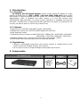
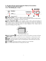
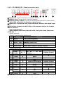
1
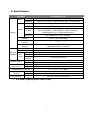
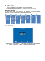
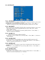
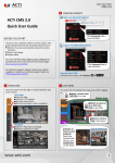
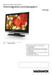
Released version 2.0
DIGITAL FULL HD QUAD SPLITTER
SC-HD04Q (D)
User's Manual
SC-HD04Q(D)
Precaution and Safety Guidelines
Please read this user’s manual thoroughly prior to use the unit for
its easy and convenient use.
• Do not install the product in the following places: extremely low or high
temperature conditions; places exposed to rain, snow, or high humidity;
places containing or exposed to oil and gas; places exposed to vibration
and shock; places under direct sunlight or exposed to outdoor weather
conditions; places exposed to radio waves (RF) or near to power lines. It
may cause low performance or malfunction of the unit.
• Do not disassemble the product or insert foreign objects.
• The unit is subject to electric shock hazard. Be careful not to get an
electric shock while using the device.
• Do not use and/or connect any devices inappropriate to the unit. It may
cause malfunction of the unit or fire.
• Use this product under temperature conditions only between 0°C and
+50°C.
• Should use the DC 12V / 1.5A adaptor certified for electromagnetic
wave and for safety.
• Should be careful not to have the lines changed when connecting them.
• Prior to turn on the device, check the cable insulation condition of the data
cable, connected with external devices.
• Before installing the product, check its voltage rate and then turn on the
power.
• Make sure to turn off the product prior to installation.
• Do not subject the product to physical shock or exert excessive force to
operate the product.
• Do not use the device when any smoke or smell is produced from the unit.
It may be subject to fire or electric shock. If any smoke or smell is
produced, please turn off the unit and remove the power cable
immediately, and contact your distributor to check the device properly.
• If the power does not turn ON, please check whether the power cable is
connected correctly or not.
• If the device does not work properly, please contact your distributor.
1
1. Introduction
1-1. Overview
SC-HD04Q, Full HD Digital Splitter, offers a high resolution display for video
signals received from 4 of SDI / HDMI / HD with 1920*1080 pixel. And it splits
the screen in various formats from full screen to 4 screens display mode, without
deterioration. Also, it displays the video clearly in a Full HD monitor with
1920*1080P high resolution. A remote control operation is available through the
RS-232C / RS-485 port. It displays the date and time, the name of channel on the
monitor, as well as when it occurs any channel loss.
1-2. Features
•
•
•
•
Supporting 4 of HD-SDI and HDMI Inputs (Selectable)
Displaying in quad; four HD-SDI /HDMI signals at real time.
Auto sequence mode
Supporting Various output mode(1920x1080, 1680x1050, 1600x1200, 1440x900,
1280x1024, 1360x768, 1024x768, 1280x720).
• Displaying date, time, channel name and the current status. (OSD)
• RS-232C/RS-485 communication port for external devices
1-3 Applications
• Where a centralized supervisory and control system is needed such as the
control center at Subway, Airport, Port and etc,
• At a control center of large buildings and express way and etc.
2. Components
Rack mount
bracket
SC-HD04Q (D)
2
Power
Adapter
User’s
Manual
3. Product Parts and Peripheral Device Connection
3-1. Name of Parts and Function
3-1-1. SC-HD04Q (D) - Front
③
④ ⑤ ⑧ ⑥
②
①
⑦
⑨
① POWER: Select ON/OFF
② CAMERA SELECT: Press the channel number which you want to watch to
display the video in full screen. When receiving SDI/HDMI signal simultaneously,
SDI and HDMI are selectable by pressing this button.
③ AUTO SEQUENCE
: In full (single) screen mode, press this button to
display the screen in auto sequence mode according to the dwell time adjusted in
each channel. Press it again to cancel the auto sequence mode. You can set the
auto screen dwell time of split screen in menu Sequence Time. Please refer to
menu 5-5-5 Sequence Time [Sec].
Full (Single) screen mode
④ MULTI SCREEN
: Please press the multi-screen button to select the Quad
screen mode.
⑤ ESC: Press this button to cancel the menu configuration in Setup Menu mode.
⑥ ENTER: Press this button to select the menu you want in Setup Menu mode.
⑦ MENU: Press this button to go to the Setup Menu mode and select the menu
you want to adjust.
⑧ ▲/▼/◀/▶: Press these buttons to adjust the menu selected.
⑨ +/- : Press these buttons to change the set value.
3
3-1-2. SC-HD04Q (D) - Rear(connection port)
①
②
③ ④ ⑤ ⑥
⑦
⑧
⑨
⑩
① SDI in X 4: Connect with the 4 of HD-SDI camera.
② HDMI in X 4: Connect the 4 of HD-SDI camera.
③ Monitor(SPOT) Output: Connect the SD(standard definition) Video Monitor.
- NTSC/PAL selectable for Monitor output format.
④ HDMI OUT: Connect the HD (High Definition) Monitor with HDMI input
port.
⑤ Serial Port: Connect the RS-232C to link external devices for remote
control function.
• Data configuration
- Data Length: 8 Bit, Start/Stop Bit: 1Bit, Parity Bit: None, Baud rate:
9,600 bps
- Packet structure
- Control Communication Data format
Byte
Value
Function
1
0xA0
STX (Launching Data)
2
0x00 ~ 0xFF
0x16 (Device Code)
3
0x00 ~ 0xFF
Address (Device ID)
4
Data byte
Control Data
5
Check Sum
Check Sum = Byte2 + Byte3 + Byte4
- Control DATA Code
NO
Hex
ASCII
Function
2
3
0x30 ~
0x33
0x47
0x48
4
0x49
I
Enter
5
0x4A
J
ESC
6
7
8
9
10
11
0x50
0x5A
0x64
0x6C
0x72
0x75
P
Z
d
l
r
u
Quad screen Display
Auto Sequence
Down
Left
Right
Up
Display Control
12
0x6D
m
Minus
Set Value change
〃
1
0~3
G
H
CH 01 ~ 04 Full
Display
Multi Screen
Menu
Remarks
13
0x70
p
Plus
⑥ VGA OUT: Connect the Monitor with the VGA input
4
Display Control
〃
Menu move
〃
〃
〃
⑦ SDI OUT: Connect the HD (High Definition) Monitor with SDI input or
Connect the other devices[1920x1080, 1280x720P]
⑧ ALARM INPUT/ OUPUT
Connect the alarm input/output port to control the split display screen by
connecting a sensor or switch from outside.
- Display mode per Foreign Alarm
External input
IN1 IN2 IN3
IN4
0
0
0
0
1
0
0
0
0
1
0
0
0
0
1
0
0
0
0
1
More than 2 channels
Input
Display mode
Normal Mode
CH 1 Full Display
CH 2 Full Display
CH 3 Full Display
CH 4 Full Display
4 Splitter Display
※ Input OFF mode =“0”, Input ON mode =“1” (The GND and the Inx produce a
short circuit )
※ When an Alarm is entered, an “A” appears in the video which have received
the alarm, in the place in which the channel loss is indicated.
※ The Alarm input will not operate if an alarm signal is entered into a lost channel.
⑧-1. Alarm Input & Button Function
In Alarm input mode or external data control model, you can only enter to
the menu mode and other function button may not operate. During the
Alarm Hold Time, press any button to escape from Alarm mode.
⑧-2. Alarm Input Cancel
When the external control data or Alarm input is eliminated, it returns to the last
display mode which has been displayed before the external data has entered, after
the Alarm Hold Time is ended. You can set the Alarm Hold Time in the Alarm Time
menu in System/Display < SETUP MENU.
⑧-3. Alarm Input Timing Structure
When the Alarm or the external data is in, the screen is displayed and the
buzzer operates as following timing diagram.
External
Data IN
Screen Display
External Data IN
External Data OFF
Alarm INPUT
mode
Last
Screen
mode
Display
※ Alarm Hold Time is delayed as the Buzzer Time does(Alarm Hold Time = Buzzer
Time)
⑧-4. How to put the Alarm in
Use a contact point signal such as switches or relay to Open/Short the Inx and the
GND (Alarm Input port). Do not use any contact point with electrical signal. It may
cause any malfunction of the device.
5
⑧-5. Alarm Output
The Alarm output provides the connect point to activate a warning lamp or alarm
bell when an alarm is entered.
⑧-6. Alarm Output Contact Point
The Alarm output contact point is under Normal Open relay of 1A/24VDC, 0.5A
/125 VAC.
※
The relay may not activate properly when an overrated power is applied in
the alarm output contact point.
⑧-7. Function
The relay maintains closed when any external input is ON, that is, when the
Alarm Input port is produced a short circuit.
The relay maintains open when any external data is off or the alarm input is off
after the alarm time is ended.
⑨ Port : for upgrading Firmware
⑩ Power Input
※ SC-HD04Q(D): DC 12V input model (Rear side)
6
4. Specification
MODEL
INPUT
OUTPUT
SC-HD04Q/(D)
SDI(4ch)
1920x1080(24p,25p,30p,60i),1280x720p(24,25,30,50,60)
HDMI(4ch)
1920x1080(30p,60i),1280x720(30p,60p), 1024x768p60
SDI
1920*1080i/p(50,60),1280*720(50p,60p)
HDM1
1920x1080(30p,60i),1280x720(30p,60p)
D-SUB
1024x768p(60), 1280x1024p(60), 1360x768p(60),
1600x1200p(60), 1440x900p(60), 1680x1050p(60),
1280x720p(50,60), 1920x1080i/p(50,60),
BNCF(Monitor)
720 x 480/60Hz, 720 x 576/50Hz,
VIDEO
FORMAT
NTSC / PAL Selectable
Screen splitting
mode
1,4
OSD(On Screen
Display)
MINI DIN(8PIN)
RS-232C
External
ALARM
Interface 14P
RS-485
T. Block
Power
Output
HD04Q(D)
POWER INPUT
HD04Q
HD04Q(D)
Power
HD04Q
Consumption
Inserting up to 16 characters
(alphabet and/or numbers)
Firmware upgrade
Connection port for external devices
Input: 4(8P), Output: 1(2P)
Connection port for external devices
DC 12V 300mA(2P)
2P Terminal Block, DC 12V 2A 이상
AC 100~240V, 50/60Hz
12V/1A
16W
Temperature/Humidity
HD04Q
Case body /
HD04Q(D)
Weight
Dimensions
※
0℃ ~ +50℃ / 0 ~ 80%
Steel/ 3.5Kg
Steel/ 3.4Kg
HD04Q /
(D)
430(W) X 44(H) X 350(D)mm
4 of HDMI input supports Audio input
7
5. SETUP MENU
• How to setup the Menu
- Press Menu button on front, and the menu will be displayed.
※ Please refer to the button function of SC-04HDS in front side (3-1-1).
5-1. Menu Structure
In menu setting mode, it is possible to set up system, input/output, display,
Date/time, channel and menu structure is displayed as below.
5-2. SETUP MENU
SSEETTUUPP MMEENNUU
SSYYSSTTEEMM SSEETT
IINNPPUUTT//OOUUTTPPUUTT SSEETT
DDIISSPPLLAAYY SSEETT
DDAATTEE//TTIIMMEE SSEETT
CCHHAANNNNEELL SSEETT
EEVVEENNTT LLIISSTT
▲
▲▼
▼::MMOOVVEE
:: SSEELLEECCTT
VV00..2200..111100552277
::EEXXIITT
Button on front: Press the Menu > Press [ENTER] to select the mode by pressing
▲▼ buttons. > Press [ESC] to cancel or go back the previous menu.
8
5-3. SYSTEM SET
SSYYSSTTEEMM SSEETT
SSYYSSTTEEMM IIDD
BBAAUUDDRRAATTEE
AALLAARRMM II//OO
AALLAARRMM HHOOLLDD
BBUUZZZZEERR OOUUTT
BBUUZZZZEERR TTIIMMEE
LLOOSSSS
EEVVEENNTT SSAAVVEE
EEVVEENNTT CCLLEEAARR
DDEEFFAAUULLTT AALLLL
▲
▲▼
▼::MMOOVVEE
000011
99660000
OONN
0033[[SSEECC]]
OONN
0055[[SSEECC]]
OONN
OONN
OOFFFF
OOFFFF
:: SSEELLEECCTT
::EEXXIITT
5-3-1. SYSTEM ID
When controlling SC-HD04Q(RS-232/RS-485) at long/short distance, you can use
the System Id. You can insert from 1 to 255.
SYSTEM SET> Go to SYSTEM ID by pressing (▲▼) buttons> Press (◀▶/+ -)
buttons to change the set-up value and select the number from 1 to 255.
5-3-2. BAUDRATE
When controlling SC-HD04Q(RS-232/RS-485) at long/short distance, you can set
the system communication speed(Baudrate) as 2400, 4800, 9600, 14400,
19200, 28800, 38400.
SYSTEM SET> Go to BAUDRATE by pressing (▲▼) buttons > Press (◀▶/+ -)
buttons to select the baudrate.
5-3-3. ALARM I/O
Alarm input and Alarm output selectable.
SYSTEM SET > Go to ALARM I/O by pressing (▲▼) > Press (◀▶/+ -) buttons to
select ON/OFF.
5-3-4. ALARM HOLD
To set the duration time of ALARM screen after the ALARM signal turns off.
SYSTEM SET > Go to ALARM HOLD by pressing (▲▼) buttons > Press (◀▶/+ -)
buttons to set the time(Second). (1 ~ 99 sec)
5-3-5. BUZZER OUT
To set the Buzzer when button is used, Alarm is detected and video signal loss is
detected.
SYSTEM SET > Go to BUZZER OUT by pressing (▲▼) buttons > Press (◀▶/+ -)
buttons to select ON/OFF.
5-3-6. BUZZER TIME
To set buzzer duration time.
SYSTEM SET > Go to BUZZER TIME by pressing (▲▼) buttons > Press (◀▶/+ -)
buttons to set the time(Second). (1 ~ 99 sec)
9
5-3-7. LOSS
To set the detection of Video LOSS.
SYSTEM SET > Go to LOSS by pressing (▲▼) buttons > Press (◀▶/+ -) buttons
to select ON/OFF.
5-3-8. EVENT SAVE
To save the event time in the EVENT LIST when ALARM/LOSS occurred
SYSTEM SET > Go to EVENT SAVE by pressing (▲▼) buttons > Press (◀▶/+ -)
buttons to select ON/OFF.
5-3-9. EVENT CLEAR
To delete all the history of event in EVENT LIST.
SYSTEM SET > Go to EVENT CLEAR by pressing (▲▼) buttons > Press (◀▶/+ -)
buttons to select ON/OFF.
5-3-10. DEFAULT ALL
To initialize the value, and the menu will be set to default mode.
SYSTEM SET > Go to DEFAULT ALL by pressing (▲▼) buttons > Press (◀▶/+ -)
buttons to select ON/OFF.
5-4. INPUT/OUTPUT SET
IINNPPUUTT//OOUUTTPPUUTT SSEETT
IINNPPUUTT
OOUUTTPPUUTT
SSDDII//VVGGAA
CCVVBBSS
▲
▲▼
▼::MMOOVVEE
11992200xx11008800ii 6600HHzz
11992200xx11008800pp 6600HHzz
SSDDII
NNTTSSCC
:: SSEELLEECCTT
::EEXXIITT
5-4-1. INPUT
To set the display input format.
INPUT/OUTPUT SET > Go to INPUT by pressing (▲▼) buttons > Press (◀▶/+ -)
buttons to set the input resolution out of 1024x768p60/1280x720p(24,25,30,50,
60Hz) /1920x1080 (50i,60i,24p,25p,30p)
5-4-2. OUTPUT
To set the video resolution outputted from HDMI/SDI/VGA.
When you connect SC-HD04Q with the monitor, set the resolution as the monitor
supports.
INPUT/OUTPUT SET > Go to OUTPUT by pressing (▲▼) buttons > Press(◀▶/+ -)
buttons to set the output resolution
10
5-4-3. SDI/VGA
To set output port as SDI or VGA (Cannot output two signals at the same time)
INPUT/OUTPUT SET > Go to SDI/VGA by pressing (▲▼) buttons >
Press (◀▶/+ -) buttons to set the output port as VGA/SDI
5-4-4. CVBS
To set the format of output video signal. (Set as NTSC in Korea)
INPUT/OUTPUT SET > Go to CVBS by pressing (▲▼) buttons > Press (◀▶/+ -)
buttons to select NTSC/PAL
5-5. DISPLAY SET
DDIISSPPLLAAYY SSEETT
CCHH TTIITTLLEE
DDAATTEE && TTIIMMEE
BBOORRDDEERR LLIINNEE
SSEEQQUUEENNCCEE MMOODDEE
SSEEQQUUEENNCCEE TTIIMMEE
OONN
OONN
OONN
CCHH 11>>22>>33>>44>>
0033[[SSEECC]]
▲
▲▼
▼::MMOOVVEE
:: SSEELLEECCTT
::EEXXIITT
5-5-1. CH TITLE
To set the channel name indication.
DISPLAY SET > Go to CH TITLE by pressing (▲▼) buttons > Press (◀▶/+ -)
buttons to select ON/OFF.
5-5-2. DATE & TIME
To set the current date and time indication.
DISPLAY SET > Go to DATE & TIME by pressing (▲▼) buttons > Press (◀▶/+ -)
buttons to select ON/OFF.
5-5-3. BORDER LINE
To set the outer border line of each channels in Quad mode.
DISPLAY SET > Go to BORDER by pressing (▲▼) buttons > Press (◀▶/+ -)
buttons to select ON/OFF.
5-5-4. SEQUENCE MODE
To display the screen in auto sequence mode according to the dwell time adjusted
in each channel. To set the SDI / HDMI switching mode and CH1~CH4 switching
mode.
DISPLAY SET > Go to SEQUENCE MODE by pressing (▲▼) buttons > Press (◀▶
/+ -) buttons to set CH1>2>3>4> or SDI<->HDMI
11
5-5-5. SEQUENCE TIME
To set display switching time by second (1~99) when selecting Auto Sequence
mode.
SYSTEM SET > Go to SEQUENCE TIME by pressing (▲▼)buttons > Press(◀▶/+ -)
buttons to set the time(Second). (1 ~ 99 sec)
5-6. DATE/TIME SET
DDAATTEE//TTIIMMEE SSEETT
DDAATTEE FFOORRMMAATT
LLOOCCAATTIIOONN
DDAATTEE SSEETT
TTIIMMEE SSEETT
▲
▲▼
▼::MMOOVVEE
YYYY//MMMM//DDDD
LLEEFFTT
1111//0066//2233
1155::3300::3300
:: SSEELLEECCTT
::EEXXIITT
5-6-1. DATE FORMAT
To set the date display format.
DISPLAY SET > Go to DATE FORMAT by pressing (▲▼) buttons > Press (◀▶/+ -)
buttons to set the FORMAT.
5-6-2. LOCATION
To set the location of the date and time.
DISPLAY SET > Go to LOCATION by pressing (▲▼) buttons > Press (◀▶/+ -)
buttons to set location of the date and time out of RIGHT, CENTER, LEFT.
5-6-3. DATE SET
To set the date.
DISPLAY SET > Go to DATE SET by pressing (▲▼) buttons > Press (◀▶/+ -)
buttons to set the date.
5-6-4. TIME SET
To set the time.
DISPLAY SET > Go to TIME SET by pressing (▲▼) buttons > Press (◀▶/+ -)
buttons to set the time.
12
5-7. CHANNEL SET
CCHHAANNNNEELL SSEETT
CCHHAANNNNEELL
IINN DDEEFFAAUULLTT
TTIITTLLEE
0011
SSDDII
CCHH0011
▲
▲▼
▼::MMOOVVEE
:: SSEELLEECCTT
::EEXXIITT
5-7-1. CHANNEL
You can select the channel you want to set up.
CHANNEL SET > Go to CHANNEL by pressing (▲▼) buttons > Press (◀▶/+ -)
buttons to set the channel
5-7-2. IN DEFAULT
When the SDI and HDMI are input together, set the DISPLAY first.
CHANNEL SET > Go to IN DEFAULT by pressing (▲▼) buttons > Press (◀▶/+ -)
buttons to select the SDI / HDMI.
5-7-3. TITLE
To revise the channel name (Title)(Max. 16 Characters)
CHANNEL SET > Go to TITLE by pressing (▲▼) buttons > Press (◀▶/+ -)
buttons to select the channel name using 63 characters.
5-8. EVENT LIST
EEVVEENNTT LLIISSTT
NNOO..
000011
000011
000011
YYYY//MMMM//DDDD
1111//0044//2299
1111//0044//2299
1111//0055//0033
▲
▲▼
▼::MMOOVVEE
HHHH::MMMM::SSSS EEVVTT
1155::3388::2200 LL
1177::0000::3300 AA
1122::0088::4400 LL
::SSEELLEECCTT
CCHH
0022
0033
0044
::EEXXIITT
It shows the channel and the time when the event of ALARM, LOSS were occurred.
(L:LOSS/A:ALARM)
13
6. Connection Diagram
※HD-SDI/HDMI input resolution supports only 1024x768p60/
1280x720p(24,25,30,50,60Hz)/ 1920x1080(50i,60i,24p,25p,30p).
14
7. Warranty Certificate
This product has passed thorough quality control and test, and if this
gets broken during normal use, we provide 12 months warranty
service.
Model No.
Serial No.
Distributor
Date you purchased
Place you purchased
Warranty Period
Name
Purchaser
Address
One (1) year from the date of purchase
• Please check this warranty indication first.
• Please contact your distributor after checking out any defect in the
products.
• The standard for repairing, replacement or reimbursement follows
Customer.
• Warranty content any defect under normal use within the warranty
service period we give you free repair service according to the
warranty certificate.
• We charge you with the fee of parts and service despite of free
warranty service period. Any breakage made without care such as:
- Breakage or trouble made by natural disaster.
- Breakage or trouble made by breaking the product guide or
manual.
- Breakage or trouble made by wrong power voltage or
frequency.
- When you want to reassemble for full system or replace parts
within warranty service period.
- When unauthorized person modified or made damage on the
product trying to repair it.
• Please note that we don’t support the breakage after warranty
service period is expired. If the customer wants to get it repaired, we
charge them with the fee.
• The specification is subject to change without prior notice for quality
improvement.
SeeEyes Co.,Ltd
#503~507, Sunil Technopia, 440, Sangdaewon-Dong, Jungwon-Gu,
Sungnam-Si, Gyeonggi-Do, Korea
TEL : +82-(0)31-777-3508
FAX : +82-(0)31-777-3512
EMAIL : [email protected]
http://www.sscctv.com/eng
15