1
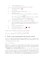
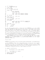
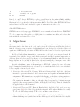
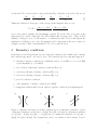
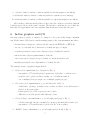
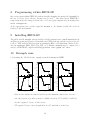
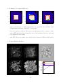
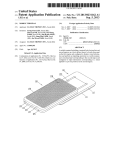
A Primer on ZEUS-3D David A. Clarke Professor of Astronomy and Physics Saint Mary’s University, Halifax NS, Canada [email protected] February, 2015 Copyright c David A. Clarke, 2015 Prerequisite: A Primer on Magnetohydrodynamics, by DAC. Contents 1 What is ZEUS-3D? 1 2 Source code management and version control 2 3 Algorithms 4 4 Staggered mesh 5 5 Boundary conditions 6 6 In-line graphics and I/O 7 7 Running ZEUS-3D 9 8 Programming within ZEUS-3D 10 9 Installing ZEUS-3D 10 10 Example runs 10 11 The future of ZEUS: AZEuS 12 1 What is ZEUS-3D? You don’t really understand something until you can compute it. Michael L. Norman, Director, SDSC ZEUS-3D is a multi-physics, covariant, computational fluid dynamics (CFD) FORTRAN77 code designed primarily for, but not restricted to, astrophysical applications. It was born from the ZEUS-development project headed by Michael Norman at the NCSA between 1986 and 1994 whose principal goal was to develop a robust, user-friendly, multi-purpose MHD code that could be released as open-source with full documentation. Principal developers other than DAC and MLN have included Jim Stone and Robert Fiedler and, over the years, various versions of the code have become publicly available. However, only the ICA version has had any significant algorithm development since 1995, and it is this version that is the subject of this primer. ZEUS-3D includes the effects of magnetism, self gravity, viscosity, a second cospatial and diffusive fluid, molecular cooling, and can be run with an isothermal, adiabatic, or polytropic equation of state. Terms in equations (1)–(6) below are colourcoded respectively; black terms being the standard equations of ideal HD. Simulations may be performed in any of Cartesian (XYZ), cylindrical (ZRP), or spherical polar coordinates (RTP), and in any dimensionality (1-D, 1 21 -D, 2-D, 2 21 -D, or 3-D). The set of equations solved are: ∂ρ + ∇ · (ρ ~v) = 0; (1) ∂t ∂~s ~ ~ + ∇ · ~s~v + (p1 + p2 + pB ) I − B B − µ S = −ρ ∇φ; (2) ∂t ∂e1 + ∇ · (e1~v) = −p1 ∇ · ~v + µS : ∇~v − L; (3) ∂t ∂e2 + ∇ · (e2~v − D · ∇e2 ) = −p2 ∇ · ~v; (4) ∂t i h ∂eT ~ ×B ~ = −L; (5) + ∇· (eT +p1 +p2 −pB )~v − µS · ~v − D · ∇e2 + E ∂t ~ ∂B ~ = 0, +∇×E (6) ∂t where: ρ is the matter density; ~v is the velocity; 1 ~s is the momentum density = ρ~v ; p1 & p2 are the partial pressures from the first and second fluids; pB is the magnetic pressure = 12 B 2 ; I ~ B is the unit tensor; µ is the shear viscosity; S is the viscid part of the stress tensor whose elements, Sij , are given by: is the magnetic induction (in units where µ0 = 1); Sij = ∂j vi + ∂i vj − 32 δij ∇ · ~v ; where ∂i indicates partial differentiation with respect to the coordinates, xi , i = 1, 2, 3, and where δij is the usual “Kronecker delta”; φ is the gravitational potential, ∇2 φ = 4πρ, in units where G = 1; e1 & e2 are the internal energy densities of the first and second fluids; L is the cooling function (of ρ and e1 ) for nine coolants (Hi, Hii, Ci, Cii, Ciii, Oi, Oii, Oiii, Sii) interpolated from tables given by Raga et al. (1997); D is the (diagonal) diffusion tensor; eT ~ E is the total energy density = e1 + e2 + 12 ρv 2 + 12 B 2 + φ; ~ is the induced electric field = −~v × B; and where the ideal equations of state close the system of variables: p1 = (γ1 − 1)e1 ; p2 = (γ2 − 1)e2 , with γ1 and γ2 being the ratios of specific heats for the two fluids. 2 Source code management and version control Version 3.6 of ZEUS-3D (dzeus36) is managed by EDITOR, version 2.2 (edit22), which comes as part of the dzeus36.tar bundle. EDITOR provides two primary functions: source code management and version control. Source code management ZEUS-3D is one behomoth code (>130,000 lines) which contains every item of physics, geometry, I/O, algorithm, and symmetry option ever developed for it. While this eases navigating within the code for programmers, it would be nice if the compiler didn’t need to waste memory or cpu computing unwanted features. EDITOR acts as a precompiler which can “turn on” and “turn off” certain segments of the code before the compiler sees it. To affect this, EDITOR commands (heralded by an asterisk * in the first column) are peppered throughout the code which allow the user to render the 3-D code a perfectly efficient 2-D code should a symmetry axis be defined. The following is a snippet of coding from the subroutine SHKSET illustrating how this is done: 2 1 2 3 4 5 6 7 8 9 10 11 12 13 14 15 16 17 18 19 20 21 22 23 24 25 *if -def,KSYM do 40 k=ksm2,kep3 *endif -KSYM *if -def,JSYM do 30 j=jsm2,jep3 *endif -JSYM do 20 i=imin,imax d (i ,j,k) = d0 v1(i+1,j,k) = v10 v2(i ,j,k) = v20 * h31b(i) * h32a(j) v3(i ,j,k) = v30 * h31b(i) * h32a(j) *if -def,ISO e1(i ,j,k) = e10 *endif -ISO *if def,TWOFLUID e2(i ,j,k) = e20 *endif TWOFLUID *if def,MHD b1(i+1,j,k) = b0 * h2ai(i+1) * h31ai(i+1) b2(i ,j,k) = b20 * h32ai(j ) b3(i ,j,k) = b30 *endif MHD 20 continue 30 continue 40 continue In a file called zeus36.mac (§7), one defines the desired EDITOR macros such as KSYM, JSYM, ISO, TWOFLUID, and MHD illustrated in this segment. Should MHD be listed among those defined, lines 19–21 are retained in the compiler copy of the code and thus compiled. Otherwise, these lines are dropped (as are all other mentions of the magnetic field throughout the code), and the magnetic field arrays are not even declared. In a non-MHD simulation, it would be wasteful indeed if one still had to declare three unwanted arrays, fill them with zeroes, and then push around zeroed magnetic fields throughout the simulation. Other EDITOR macros include those for geometry (XYZ, ZRP, RTP), physics (GRAV, RADIATION, etc.), I/O (PLT1D, RADIO, etc.), algorithm (MOC, RIEMANN, etc.), and compiler (GFORTRAN, IFORT, etc.). Version control EDITOR can also manage change decks, files separate from the main code in which the user can direct EDITOR to delete, add, or change lines in the code before the code is compiled. The master copy of the code is left untouched, and multiple developers can have working change decks until such time when it is decided to merge all change decks into the code permanently, creating the next version. Typical syntax is as follows: 1 2 3 4 5 6 7 8 *replace ctran1.130,137 c c b) Interpolate "v1" to zone centres. c call x1fc3d ( v1, v1twid ) *delete ttran1.150,155 *insert cmoc3.230 *if -def,ISYM 3 9 10 11 12 do 10 i=ism2,iep3 *endif -ISYM vel1(i) = v1 i,js,ks) 10 continue Lines 1, 6, and 7 direct EDITOR to replace several lines in subroutine CTRAN1 with the given lines, delete six lines from subroutine TTRAN1 (and replace them with nothing), and then insert a do-loop after line 230 in subroutine CMOC3. Note that other EDITOR directives such as lines 8 and 10 can be included as part of an insertion into the code. Other EDITOR features EDITOR can also tidy up sloppy FORTRAN, create a numbered text file for a FORTRAN 77 code, compare two files, split a code (file) into its constituent modules, and a few other tasks useful in developing large codes. 3 Algorithms There are a semi-infinite number of ways one can difference differential equations (so that the former tend to the latter as δt → dt), and yet not all of them are stable in the realm of finite δt. Over the years, a variety of algorithms have been developed to solve the differenced equations of MHD stably, and users of ZEUS-3D have the benefit of decades of person years of development and experience. In broad brush terms, dzeus36 is a conservative code based on a staggered mesh. It is upwinded in both the entropy and Alfvén waves and stabilised against compressive oscillations (fast and slow waves) by the use of von Neumann-Richtmyer artificial viscosity. Interpolations can be as high as third order, though formally the convergence rate of the code can be as low as first order, depending on how it is configured. Specific algorithms—many of them unique to ZEUS-3D—designed to stave off certain types of numerical instabilities not addressed by the attributes listed above are tabulated below, roughly in chronological order. 1. Consistent Advection (CA; Norman, Wilson, & Barton, 1980, ApJ, 239, 968) was invented to prevent numerical drift between mass and angular momentum fluxes in axisymmetic HD simulations, and settled the dispute on whether rotating matter accreting onto a point mass formed a disc or torus (NWB proved it to be a disc). CA remains in dzeus36 to this day, though it has been found to be injurious when applied to the energy equation (Clarke, 2010, ApJS, 1897, 119). Thus, as default, CA is applied only to the momenta. 2. Constrained Transport (CT; Evans & Hawley, 1988, ApJ, 332, 659), based on a staggered mesh (§4) is a method by which the magnetic field—when initialised to satisfy ~ = 0—will always satisfy ∇ · B ~ = 0 to machine round-off error. ∇·B 3. Consistent Method of Characteristics (CMoC; Clarke, 1996, ApJ, 457, 291) is an algorithm which imposes upwindedness in the Alfvén speed and by which the velocity and 4 magnetic field required to calculate the induced electric field are interpolated implicitly over a plane, rather than explicitly in one direction at a time. This is necessary to prevent a numerical phenomenon in which a localised weak magnetic field could be promoted by several orders of magnitude in a single time step because of inconsistently determined interpolations. 4. Finely Interleaved Transport (FIT; Clarke, unpublished). Certain multi-dimensional problems (e.g., 2-D transport of Alfvén waves) could not be done by any previous version of ZEUS without features being broken up into stripes perpendicular to the direction of propagation. FIT cures this problem. In addition, there are three interpolation algorithms (donor cell, van Leer’s second order interpolation, and Colella & Woodward’s piecewise parabolic interpolation), three selfgravity algorithms (Successive Over-relaxation, Full Multi-grid, and FFT), and two kinds of artificial viscosity (von Neumann-Richtmyer algorithm of 1950, and a tensor algorithm). 4 Staggered mesh ρ, e v1 , B1 E1 E2 E3 ZEUS-3D is based on a staggered mesh as shown in Fig. 1. Scalars (ρ, e; black) are zone-centred, primary vector components (~v , ~ red) are face-centred, and derived vector B; ~ ind ; cyan) are edge-centred. components (E Two main benefits of using a staggered mesh are flux computation and preserving ~ = 0. On the former, consider the dif∇·B ferenced continuity equation when ~v = v1 x̂1 : x2 x3 x1 v2 , B2 ρn+1 i n+ 1 ρni n+ 1 n n − ρi− 12 v1,i ρi+ 12 v1,i+1 − 2 2 = − , n δt δx i Figure 1: The staggered mesh depicted in the where superscripts indicate time step, sub1-2 plane. scripts zone number, and where the half super/sub-scripts indicate some sort of time-centring/spatial interpolation. This equation can then be solved for ρn+1 , the value of ρ at zone i at the next time step. i Evidently, the fluxes (ρv) are computed at the zone faces (i ± 21 ). To do this, the zonecentred ρ must be interpolated to the zone faces, a time-consuming effort fraught with a host of numerical “landmines”. On the other hand, face-centred v1 (by virtue of the staggered mesh) need not be interpolated, providing significant computational relief. ~ = 0 (the solenoidal condition). Consider More significant is the preservation of ∇ · B the evolution of B1 and B2 with 3-symmetry where the 1- and 2-components of the induction equation are: ∂B1 ∂E3 ∂B2 ∂E3 = ; = − ∂t ∂x2 ∂t ∂x1 since the 3-derivatives are zero. Differencing this (with the 3-component of the induced 5 electric field, E3 , located at the 3-edges as shown in Fig. 1 with the cyan circle-dots), we get: δB1,i,j E3,i,j+1 − E3,i,j ; = δt δx2 δB2,i,j E3,i+1,j − E3,i,j . = − δt δx1 (7) Taking the differenced divergence of the changes in the magnetic field, we get: ~ = δB1,i+1,j − δB1,i,j + δB2,i,j+1 − δB2,i,j , ∇ · δB δx1 δx2 now a zone-centred quantity. By substituting equation (7) for the δBs, every term on the ~ is numerically divergence-free. Thus, if B ~ is right hand side cancels identically, and δ B initialised divergence free, it will remain so to numerical round off error throughout the simulation. I challenge you to place the magnetic field components at the zone-centres, for ~ = 0 to round-off error! example, and try to find a way maintain ∇ · B 5 Boundary conditions Boundaries are set independently for each of six grid boundaries and, within each boundary, the boundary type may be set zone by zone. Ten boundary types are currently supported: 1. reflecting boundary conditions at a symmetry axis (r = 0 in ZRP, θ = 0 or π in RTP) or grid singularity (r = 0 in RTP); 2. non-conducting reflecting boundary conditions (Fig. 2a); 3. conducting reflecting boundary conditions (Fig. 2b); 4. continuous reflecting boundary conditions (Fig. 2c); 5. periodic boundary conditions; 6. “self-computing” boundary conditions (for AMR); 7. transparent (characteristic-based) outflow boundary conditions (not implemented); a) b) c) Figure 2: Magnetic field lines across three different types of reflecting boundaries. a) nonconducting boundaries ⇒ Bk (out) = −Bk (in), B⊥ (out) = B⊥ (in); b) conducting boundaries ⇒ Bk (out) = Bk (in), B⊥ (out) = −B⊥ (in); and c) continuous boundaries ⇒ Bk (out) = Bk (in), B⊥ (out) = B⊥ (in). The designations k and ⊥ are relative to the boundary normal. 6 8. “selective” inflow boundary conditions (useful for sub-fast-magnetosonic inflow); 9. traditional outflow boundary conditions (variables constant across boundary); 10. traditional inflow boundary conditions (suitable for super-fast-magnetosonic inflow). All boundary conditions strictly adhere to the solenoidal condition, even where different boundary types adjoin on the same boundary. The first five conditions are exact, while the latter five are approximate and can sometimes launch undesired waves into the grid. 6 In-line graphics and I/O One may request a variety of output to be dumped to disc periodically during a dzeus36 run. Each format of I/O has its own file-naming syntax of the form zxvvnnnid.mm, where: - the first letter is always z to indicate the file came from ZEUS-2D or ZEUS-3D; - x is one- (occasionally two-) characters to identify the type of output; - vv (when present) is a user-set two-character tag to identify the variable; - nnn is the three digit sequential number of the file; - id is a user-set two-character tag to identify one run from another; and - mm (when present) is a two-digit number to identify the slice. The principle forms of graphical output include: 1. 1-D line plots: zpnnnid.mm (e.g., left panel of Fig. 3) - any number of 77 variables plotted against any of the three coordinate axes - variables can be plotted as lines or using one of 6 different symbols - one or multiple plots per graph; one or multiple graphs per page 2. 2-D contour plots: zqnnnid.mm (e.g., second left panel of Fig. 3) - “buffet-style” plotting: as many as two scalars and three vector fields may be plotted on the same graph - scalars plotted as colour or greyscale, and/or lines - different vector fields plotted with different colours 3. 2-D pixel dumps: zivvnnnid.mm [e.g., second right panel (top) of Fig. 3] - 2-D slices through datacube assembled to an mpeg automatically at run’s end - any number of 78 variables may be plotted in one or more planes 4. “RADIO” dumps: zRvvnnnid [e.g., second right panel (bottom) of Fig. 3] 7 Timestep (waves) 1.0 0.8 0.6 0.6 x2 ρ 0.8 0.4 0.4 0.2 0.2 0 ρ vpol 100 200 300 400 500 0.0 0.2 0.4 0.6 0.493 0.472 0.452 0.431 0.411 0.390 0.370 0.349 0.329 0.308 0.288 0.268 0.247 0.227 0.206 0.186 0.165 0.145 0.124 0.104 0.8 Plot file ‘zp001xd.01.ps’ created on 12/02/2015 at 11:31:05. t = 80.0000, nhy = 506, x2a(1) = 0.000, x3a(1) = 0.000. −2.0 δt −2.2 δtQ δtcs −2.4 δtvA −2.6 −2.8 −3.0 0.0 0.1 0.2 0.3 0.4 t x1 x1 log(δt) Density 1.0 Plot file ‘zq001yr.01.ps’ created on 10/02/2015 at 18:10:17. t = 0.50000, nhy = 500, x3a(1) = 0.000. Plot file ‘ztp001yr.ps’ created on 10/02/2015 at 18:10:22. t = 0.50000, nhy = 500. Vectors: v1,max = 1.586 v1,min = 6.344 × 10⁻² Scalars: q1,max = 0.503 q1,min = 9.372 × 10⁻² Figure 3: From left to right: 1-D line (bubble) plot of the density in the Brio & Wu shock tube problem; a colour contour plot showing both density and velocity vectors from the OrzsagTang vortex; a 2-D pixel plot of the velocity divergence (top) and a line-of-sight integration dump of the synchrotron emissivity in a low resolution (643 ) run of super-Alfvénic turbulence; and a time slice plot showing how the time-steps, δt, evolve over the course of a simulation. - line-of-sight integrations from an arbitrary and possibly moving vantage point automatically assembled to an mpeg at run’s end - any number of 25 variables to select, including all primitive variables, Stokes I, Q, and U parameters, bremsstrahlung, and a number of other derived quantities. 5. History plots: ztpnnnid (e.g., right panel of Fig. 3) - 97 different variables including variable extrema, time steps, and volume integrals plotted against problem time - used to monitor a simulation, track conserved quantities, variable extrema, etc. Other formats of I/O to and from dzeus36 include: 1. Input deck (inzeus) is the only input data file ZEUS requires, and includes all namelist specifications 2. Restart dumps (zrnnnid) is an image of the simulation suitable for resuming the simulation from the time the dump was created. 3. HDF dumps (zhvvnnnid) are HDF4 files of any number of 53 variables, including a “total HDF dump” which includes all primitive variables, suitable for post-processing and graphics (but not a restart). 4. “Corks” (zcnnnid) are passive particles injected into the flow to keep track of 63 different quantities as functions of time in Lagrangian coordinates. 5. Logfile (zlnnnid) records namelist choices, grid information, and various terminal messages generated throughout the run. 8 0.5 6. Display dumps (zdvvnnnid.mm) are 2-D slices of numerical values for any number of 50 variables arranged on a grid with zone indices labelling the horizontal and vertical axes; primarily used for debugging. Plots shown in this primer are in-line features of dzeus36. Some plots may be created after a run by using the post-processing ancillary codes PLOTZ and RADIO, both included in dzeus36.tar.gz with a user manual. The former creates 1-D and 2-D plots, while the latter does line-of-sight integrations at various vantage points through a simulation “still”. Both of these codes take “total HDF4 dumps” as their input. 7 Running ZEUS-3D ZEUS-3D is run by preparing two, perhaps three ascii files. These are: 1. user-written change deck(s) to add, modify, or delete code in dzeus36 (optional); 2. zeus36.mac, a “macro file” containing all macros directing EDITOR which portions of the code are to be passed to the compiler; 3. dzeus36.s, a “script file” containing unix commands that takes care of: - assembling all files needed for compilation and linking including libraries, userwritten change decks, and zeus36.mac; - launching EDITOR to perform the precompilation steps; - launching the makefile created by EDITOR to create the executable, xdzeus36; - creating the input file inzeus required by xdzeus36 to do the calculation. Once zeus36.mac, dzeus36.s, and possibly the change deck(s) are prepared as required, they should be placed in their own directory and the command: csh -v dzeus36.s should be issued at the unix prompt. If all goes well, the executable (xdzeus36) and input file (inzeus) are created in the directory. Typing xdzeus36 at the prompt then launches the run. If run in the foreground, dzeus36 can recognise numerous “interrupt messages” which can be issued at the terminal. These include asking how far along the simulation is, requesting a plot to be generated, changing the length of time the simulation is to run, or even stopping cleanly (or aborting abruptly). The reader is referred to the user manual for details. For an ideal MHD run and a modest amount of I/O, dzeus36 is about 95% parallel, which means it can make good use of sixteen processors, but not necessarily 32. EDITOR can be directed to prepare both the code and even the user’s change decks for a parallel application using OpenMP. In principle, there is very little the user needs to do (other than write thread-safe code) to prepare an executable to run in parallel. Working examples of zeus36.mac and dzeus36.s are included in the public domain tarball dzeus36.tar.gz, and detailed descriptions are given in the user manual. 9 8 Programming within ZEUS-3D One can program within ZEUS-3D without actually changing the master file (dzeus36) by the use of change decks, already discussed in §§2 and 7. One then directs EDITOR to temporarily merge the change deck into the code before (pre)compilation by including a line *read <changedeck> at the appropriate place in the script file dzeus36.s. For further details, the reader is referred to the user manual. 9 Installing ZEUS-3D The public tarball, dzeus36.tar.gz, includes detailed instructions to install dzeus36 and its ancillary programs and libraries on virtually any UNIX platform, and the reader is directed to those. This includes Windows laptops running RedHat or Ubuntu linux, MacBook Pro, and any mainframe (IBM, SUN, Cray, SGI, etc.). Further, dzeus36 may be compiled by a variety of FORTRAN compilers including gfortran, ifort, pgf90, and others. 10 Example runs 1.0 1.0 2.5 0.8 0.8 2.0 0.6 0.6 eT p1 ρ 1. Revisiting the 1-D shock tube example from the Primer on MHD 1.5 0.4 0.4 1.0 0.2 0.2 −0.0 1.0 −0.2 0.8 −0.4 0.6 0.8 0.4 B2 v2 v1 0.6 0.4 −0.6 0.2 0.2 −0.8 0.0 0.2 0.4 0.6 x1 0.8 1.0 0.0 0.2 0.4 0.6 x1 0.8 1.0 0.0 0.2 0.4 0.6 0.8 1.0 x1 - lines are the analytical solution, bubbles are the dzeus36 solution zone for zone. - smooth portions of profiles accurate to within a fraction of 1% (width of bubbles) - shocks “captured” by two or three zones - CD captured by two zones, though there is a 1% undershoot at its base 10 2. 2-D transport of a square Alfvén wave v⊥ 0.2 0.1 x2 0.0 0.0 0.0 −0.1 −0.1 −0.1 −0.2 −0.2 −0.2 −0.2 −0.1 0.0 0.1 0.2 x1 v⊥ 0.2 0.1 x2 0.1 x2 v⊥ 0.2 −0.2 −0.1 0.0 0.1 −0.2 −0.1 0.2 x1 0.0 0.1 0.2 x1 - square perturbation to v⊥ (left panel) launches two oppositely directed Alfvén waves along magnetic field lines, oriented 45 ◦ from x1 -axis - periodic boundary conditions; Alfvén waves pass through grid twice, return to origin - without FIT (finely interleaved transport), waves develop spikes in direction orthogonal to propagation (centre panel) - with FIT, Alfvén wave suffers only normal isotropic numerical diffusion (right panel) 3. 3-D super-Alfvénic turbulence 2.0 log(E) 0.0 ET EK E1,int EB !2.0 !4.0 !6.0 !8.0 0 0 20 40 t 11 60 80 This 1283 simulation (images on next page) shows how a weak magnetic field (β ∼ 1010 ) can be boosted to equipartition (β ∼ 1) in an isothermal turbulent medium, such as the ISM or in the lobes of extragalactic radio sources. This super-Alfvénic turbulence is a difficult simulation for MHD codes to do, and is what motivated the development of the Consistent Method of Characteristics (CMoC) in the early 1990s. From left to right, top to bottom, the first five panels show line-of-sight integrations of: density; magnetic energy density; ∇ · ~v (where dark lines show shocks); optically thin synchrotron emission (what a radio telescope might observe); and fractional polarisation ~ of the synchrotron emission, including polarisation B-vectors superposed. The sixth panel shows how the principle energies evolve in time, notably the magnetic energy which grows as a power law until it is saturated and in equipartition with the thermal energy density. 11 The future of ZEUS: AZEuS AZEuS (Adaptive Zone Eulerian Scheme) is a marriage of Adaptive Mesh Refinement—AMR— and ZEUS-3D. AMR allows numerous grids of varying resolution to be automatically created or destroyed, depending on where resolution is needed. Each grid passes information to abutting ones in a completely conservative fashion, enabling simulations with much higher effective resolution than ever before. AZEuS is still under development, and will be released into the public domain in due course. However, it has been used by us already to perform simulations of protostellar jets. Now, we think we understand how protostellar jets are launched at the sub-0.1 AU scale, but can this account for the observations of protostellar jets at the 1,000 AU scale? You can read more about AZEuS and its maiden simulation in: Ramsey & Clarke, ApJ, 2011, 728, L11 Ramsey, Clarke, & Men’shchkov, ApJS, 2012, 199, 13 12 ($$%&'"%+%)*% !"#$$%&'"%($$%)*% ,$"$$$%&'%-(%.)/"%("+$$%)*% Figure 4: Inserts showing relative scale lengths of pre-AZEuS MHD simulations of protostellar jets and their observed counterparts (in this case, HH34). !"#$$%&'()*+,&(,+-$./)01/'+23/4%&5$'.&/'6)+#/5702$-+ .&50)61/'+/8+2,$+6.2-/7,*.)+9$2+&'+::;<+ Figure 5: First AZEuS simulation: axisymmetric protostellar jets to 4,000 AU at 0.01 AU resolution. Colour contours depict the Alfvénic Mach number; contours, magnetic field lines. 13