1
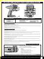
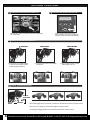
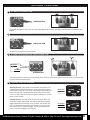
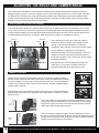
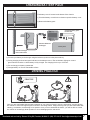
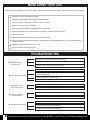
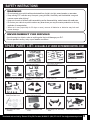
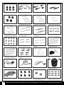
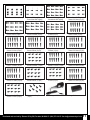
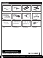
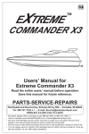
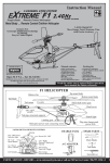
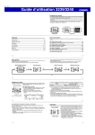
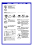
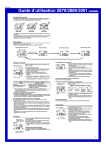
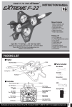
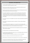
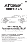
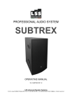
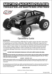
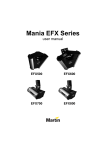
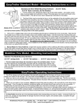
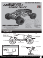
INSTRUCTION MANUAL
XGX 3
POWER TRUCK
Manual Contents
• General information
• 2.4GHz radio system R/C
• Driving instructions
• Angle adjustment instruction
• Charging instructions
• Troubleshooting
• Safety instructions
• Parts list (by number)
PARTS - SERVICE - REPAIRS
OPEN Mon - Fri 9 am-6 pm ... Sat 10 am-3 pm (EST)
Distributed and serviced by: Extreme RC by RSI ... Ferndale, MI 48220
Phone: (586) 757-1336 Email: [email protected]
Website: www.extremercbyrsi.com
14
Packing List
(1) Power truck
(1) 2.4GHz R/C
(1) A/C adapter
(1) Balancer
(1) Warranty card
(1) Instruction manual
(1) Battery
7.4V, 850mAh
PACKING LIST
XGX 3 Power Truck
Outer Shell
Motor
Metal Outer Spring /
Front Shock Set
Metal Outer Spring /
Rear Shock Set
Power Switch
Front Wheels
Battery Compartment
Parts Included
A / C charger (x1)
Controller
Balancer (x1)
Control Interface
Rear Wheels
Steering Wheel
Trigger
7.4V, 850mAh Battery (x1)
Battery case
Distributed and serviced by: Extreme RC by RSI, Ferndale, MI 48220 P: (586) 757-1336 E: [email protected]
1
GENERAL INFORMATION
This user's manual is designed for use with your XGX 3 Power Truck and contains the
instructions you will need to operate, assemble / disassemble after 60-day warranty, maintain
and troubleshoot your R/C unit. We want users to enjoy our R/C products and to operate
them with care. Failure to operate your vehicle in a safe and responsible manner may
result in property damage, or injury to yourself or others.
This product is not a toy.
IT IS AUTHENTIC HOBBY GRADE.
It is not suitable for users under 14 years old unless they are supervised by adults.
Carefully read and follow all instructions in this manual. Failure to follow the
instructions will be considered abuse and/or neglect and may void the 60 - day
warranty.
Before driving your unit, please read this manual completely and examine your vehicle and radio control for any
defects. Radio waves are subject to interference. Radio interference can cause loss of control of your vehicle.
This product is fully assembled at the factory. We do not take any responsibility for damage and / or accidents that
occur as the result of custom modifications and/or incorrect operation.
Your vehicle is designed to run on uneven or rough terrain. However: dust, sand, water and carpet fiber can lodge
in the working parts of your cars and can damage your vehicle if not removed promptly. We do not warranty your
vehicle from damage due to outside elements including sand, dirt or water. The user is responsible for the
maintenance and safe operation of this vehicle.
Never attempt to re-assemble any electronic components. These have been carefully calibrated at the factory.
If your vehicle becomes stuck, release the throttle, then retrieve it by hand. Do not continue to apply the throttle or
you may damage the motor and / or the ESC / receiver unit.
This vehicle requires one battery pack (included in the car or in the packaging). Make sure the vehicle’s batteries
have a sufficient charge before driving - insufficient charge may result in a loss of control. The radio controller
requires 3 x ‘AA’ batteries (not included in the packaging). Always remove batteries from the vehicle and the radio
controller when not in use.
For better performance, some adjustments may be necessary. Take care and do not cut yourself while using tools
to adjust or upgrade your vehicle.
Only use Extreme RC manufactured parts to upgrade your car. If you perform a drivetrain upgrade, replace the entire
system (such as motor, ESC / receiver unit...ie.) so that all components are properly matched. Any malfunction
incurred by custom modification will void your warranty.
2
Distributed and serviced by: Extreme RC by RSI, Ferndale, MI 48220 P: (586) 757-1336 E: [email protected]
GETTING FAMILIAR WITH YOUR 2.4GHZ RADIO SYSTEM
LEFT
RIGHT
2.4 GHz
A
STOP
FORWARD
B
BACKWARD
DIGITAL PROPORTIONAL SYSTEM
1
4
3
ST. TRIM
N
ST. D/R
R
TH. TRIM
N
ST.REV
R
TH.REV
6
C
REMOTE CONTROL
A: Steering wheel
B: Trigger
C: Battery case
8
2
5
7
o
PAIR
I
REMOTE CONTROL INTERFACE
1: Steering trim
2: Dual / rate servo throw
3: Throttle trim
4: Steering reverse
5: Throttle reverse
6: Power indicator light
7: Battery indicator light
8: Power switch
REMOTE CONTROL
(A) Steering Wheel: Turns the model left and right.
(B)Trigger: Controls acceleration and braking. Pull to accelerate, release to decelerate, and push forward to brake. Pushing forward
after the car has stopped will put the car in reverse.
(C) Battery Case: Requires (3) ‘AA’ batteries (not included).
REMOTE CONTROL INTERFACE
(1) Steering Trim: Adjusts the center trim of the steering servo, aligns wheels.
(2) Dual / Rate Servo Throw: Adjusts the center trim of the throttle / steering servo distance. Fine tunes the R / C steering wheel.
(3) Throttle Trim: Adjusts the center trim of the throttle (forward and backward) and sets idle speed.
(4) Steering Reverse: Electronically switches the direction of servo travel, reversing the backward-left / forward-right relationship
of the steering wheel to a forward-right / backward-left relationship.
(5) Throttle Reverse: Electronically switches motor operation, reversing the pull-forward / push-reverse relationship of the throttle
to a pull-reverse / push-forward relationship.
(6) Power Indicator Light: Stays solid red when the R / C is turned on. R / C batteries need to be changed when both Power and
Battery Indicator Lights are flashing.
(7) Battery Indicator Light: Stays solid green when batteries are fully charged. The light starts flashing when battery power is low.
Batteries need to be changed when both Power and Battery Indicator Lights are flashing
(8) Power switch: Turns the remote controller on and off.
BATTERY INSTALLATION
1) Slide back the battery cover as shown and, following the polarity
illustratons, insert three ‘AA’ batteries.
2) Slide back the battery cover after batteries are installed.
NOTES:
- Use batteries of same type / brand.
- Remove batteries from R / C if not in use.
- Always check the battery power.
- Dispose of used batteries properly.
NEW ALKALINE BATTERIES- STRONGLY RECOMMENDED
Distributed and serviced by: Extreme RC by RSI, Ferndale, MI 48220 P: (586) 757-1336 E: [email protected]
3
DRIVING YOUR CAR
1 TURN ON THE RECEIVER ON YOUR UNIT
2
The ON / OFF switch is located in the rear underneath
the truck shell.
TURN ON THE RADIO CONTROLLER
Switch on the power switch on the
radio controller. Your unit is connected
with your radio controller automatically.
3 CHECK STEERING PERFORMANCE
CENTER
TURN LEFT
2) To turn left, turn the control wheel
towards you.
1) To keep the car running straight
in line, do not move the control
wheel. (Keep it centered)
4
TURN RIGHT
3) To turn right, turn the control
wheel away from you.
CHECK TRIGGER RESPONSE
PUSH IT
FORWARD
PULL IT
BUCK
CENTER
A
B
C
A. Pull the trigger back to accelerate, release it to decelerate and push it forward to brake.
B. To stop your running car, release the trigger to neutral position.
C. Pushing the trigger forward a second time activates the reverse feature.
4
Distributed and serviced by: Extreme RC by RSI, Ferndale, MI 48220 P: (586) 757-1336 E: [email protected]
DRIVING YOUR CAR
5 5TO TUNE THE STEERING TRIM
STEERING TRIM
Gently pull the trigger to allow your car to run slowly. Meanwhile, tune the steering trim to allow the front wheels to be
aligned.
6 6TO TUNE THE THROTTLE TRIM
THROTTLE TRIM
Throttle trim is used to set your idle speed.
7
TO TUNE THE STEERING DUAL RATE CONTROL DIAL
Decrease
Increase
STEERING D/R
This dial adjusts the overall travel of the steering servo. Turn the dial towards right for maximum steering. Turn the dial
to left to reduce the steering level.
8
STEERING / THROTTLE REVERSE
Steering Reverse: This switch will reverse the normal RC-to-car
steering wheel relationship. Normally, turning the steering wheel
forward will turn the car to the right, and turning it back toward you
will turn it to the left. The Steering Reverse switch will cause the
car to turn right when you turn the wheel back toward you, and left
when you turn it away.
Throttle Reverse: This switch will reverse the normal RC-to-car
accelerator trigger relationship. Normally, pulling the accelerator
trigger backward will cause the car to go faster, and reverse the
car. The Throttle Reverse switch will cause the car to slow, stop,
and reverse when you pull the trigger, and to go forward faster
when you push the trigger away from you.
N: Normal
R: Reverse
Bind/Mode
N: Normal
R: Reverse
Bind/Mode
Distributed and serviced by: Extreme RC by RSI, Ferndale, MI 48220 P: (586) 757-1336 E: [email protected]
5
ADJUSTING TOE ANGLE AND CAMBER ANGLE
Your model can be customized to enhance speed and performance. Simple adjustments and easily maintained
settings will assure optimum operation and performance. When making adjustments, do so only in small increments
and always check for other parts of the vehicle that are affected. Many aftermarket options are available to make
your R/C vehicle faster and stronger. Please read this section carefully and always make sure to write down base
settings in case you need to refer to them at a later date.
FRONT STEERING TOE ANGLE ADJUSTMENT
The front steering toe angle has a dramatic effect on how your car performs and how your tires wear. You can have
toe-in, zero toe or toe-out. This can be adjusted by tuning the length of the steering linkage screwbolts as shown in
the figure below. Before tuning, the steering linkage screwbolts should be removed from the vehicle. Measure the
desired length by unscrewing or screwing in. After adjustment is complete, re-install them in the car.
Zero Toe
Toe Out
Toe In
Zero Toe
Toe Out
Toe In
Toe-in will be less reactive and cause the vehicle to
under steer (the front wheels push straight on while
turning). This can be advantageous for operators
struggling to get a tight tire grips with driving the vehicle.
Toe-out will be more aggressive on the steering
response especially on small steering inputs. This will
make the car want to over steer (rear wheels slide on
small steering inputs). This is useful as a race tuning aid
to gain extra steering.
Adjust in here
Adjust in here
Zero toe will make the front wheels run straight and
make the car very neutral. Tire wear will also be
reduced and the vehicle will feel easier to drive.
ADJUST IN HERE
CAMBER ADJUSTMENT
Camber can be adjusted on all 4 wheels of the car. You can have negative camber or
positive camber, which will affect the contact patch of the tire both statically and while
cornering. Camber is mainly used to control the wear of the tire. You should adjust the
camber to equal the wear all across the surface of the tire. Camber is adjusted by the
upper linkage screwbolts.
Note: Before tuning, the screwbolts should be removed from the vehicle. Measure the
desired length by unscrewing or screwing in. After adjustment is complete, re-install
them in the car.
Positive
camber
Negative
camber
6
FRONT
ADJUST IN HERE
REAR
This is an example of positive camber. The bottom of the wheel is closer
to the center of the car compared to the top of the wheel. Positive camber
will give less contact area in the corner and less grip. Excessive positive
camber will cause less grip and uneven wear.
This is an example of negative camber. The top of the wheel is closer to
the center of the car compared to the bottom of the wheel. Negative camber
will give more contact area in the corner and more grip. Excessive negative
camber will cause less grip and uneven wear.
Distributed and serviced by: Extreme RC by RSI, Ferndale, MI 48220 P: (586) 757-1336 E: [email protected]
CHARGING BATTERY PACK
The battery cover is located on the bottom of the chassis.
1) Pinch the battery cover blocks as shown to open the battery cover.
2) Remove the battery pack.
Connect battery pack
to balancer
Charger
Balancer
Connect balancer
to charger
7.4V
Battery Pack
HIGH PERFORMANCE
BATTERY-PACK
Connect charger
to the wall outlet.
3) Connect your battery to the charger using the balancer (as shown in the picture above).
4) During charging, both red and green indicator on the balancer are on.The red indicator light goes out and
green indicator remains on when battery is fully charged. The charging time is up to 2.5 hours.
5) Do not charge your battery unattended.
6) Charge battery on flat non-flammable surface.
DRIVING PRACTICE
PRACTICE
Once you are comfortable with the basic operation of your vehicle (forward, reverse, and turning), practice driving
the vehicle in circles and figure-eights as shown in the image above. Keep practicing until you are comfortable with
steering, acceleration, and braking at low speeds. Once you have mastered the basics, you will be able to control
the vehicle at increasingly faster speeds on more challenging tracks and terrain.
Distributed and serviced by: Extreme RC by RSI, Ferndale, MI 48220 P: (586) 757-1336 E: [email protected]
7
MAINTAINING YOUR CAR
After operating your Extreme RC vehicle, perform the following maintenance checks to preserve your car’s performance.
Inspect your car for any obvious damage.
Check the gears for wear, debris or broken/slipping teeth.
Check the wheels and tighten the wheel screws as needed.
Check for loose screws in the chassis.
Check the wiring for frayed or damaged wires or connectors.
Check the steering servo, which will wear out over time - replace when neccessary.
Check all batteries.
Keep the chassis clean and free of sand, dust and moisture.
Remove and clean the motor if necessary. (Never attempt to re-assemble the motor - you will damage it and
void the warranty.)
Clean the car body with a soft lint-free cloth.
Remove all batteries when not in use.
TROUBLESHOOTING
1. Check to see if both transmitter and car are on.
A. The vehicle does
not work at all.
2. Charge battery pack.
3. Check to see if there are damaged parts.
1. Replace or charge the battery pack and / or the R / C batteries.
B. The vehicle runs slowly.
2. Make sure the vehicle is geared properly and pinion / spur
gears are tightened.
3. Clean all bushings or ball bearings.
4. Check for stripped or dirty gears.
C. The throttle works,
but not the steering.
D. It steers, but throttle
is uncontrollable.
1. Check if the servo feels jammed, try centering it by hand.
2. Check the whole steering system.
1. Check to see if there are damaegd parts.
2. Replace or charge the battery pack and / or the radio batteries.
1. Check gear mesh between spur gear and pinion.
E. The vehicle runs noisily
2. Check for stripped and / or dirty gears.
3. Clean and oil bushings or ball bearings.
8
Distributed and serviced by: Extreme RC by RSI, Ferndale, MI 48220 P: (586) 757-1336 E: [email protected]
SAFETY INSTRUCTIONS
WARNING
• Do not operate your vehicle with an obstructed line of sight, at night, around crowds, or near water.
• Keep moving R / C vehicles away from pets, young children, the elderly and the disabled - use good
common sense when driving!
• Keep out of reach of children while assembling and/or disassembling; model comes with small parts.
• Do not run your vehicle on public roads or any area where you may encounter pedestrian or moving
methods of transportation.
• When not in use (especially for 30 days or more), remove all batteries or batteries may leak and
cause damage.
ENVIRONMENT FOR DRIVING
• Avoid running into objects, water or anything else that could damage your R / C.
• Do not operate in snowy, rainy or poor weather conditions.
SPARE PARTS LIST: AVAILABLE AT WWW.EXTREMERCBYRSI.COM
2 Servo Cover / Motor Guard
Chassis Side Plates A
# Front and Rear Upper Arms /
6 Shock Towers / Chassis Side
Plates B
#
10 Steering Hubs (L/R)
Rear Hub Carriers (L/R)
#
14 Battery Door / Motor / Gear
Cover
#
1 Bottom Chassis
#
5 Gear Case / Suspension Mount
#
9 Steering / Servo Saver Assembly
/ Battery Door Block / Lock
#
13 Spur Gear / Diff. Gears
Assembly
#
#
#
#
#
3 Drive Shafts / Steering and
#
7 Front Shock Set
#
11 Front Hub Carriers (L/R)
#
15 Front Body Post / Rear Body
Posts
#
Servo Linkage Set
4 Front / Rear Lower Arms
8 Rear Shock Set
12 Wheel Hex. (8 pcs)
16 Bumpers Assembly
Distributed and serviced by: Extreme RC by RSI, Ferndale, MI 48220 P: (586) 757-1336 E: [email protected]
9
17 Flange Lock Nut M4
#
18 Shock Tower Braces
#
19 Rear Axles / Diff. Outdrives
#
20 Front Axles
#
21 Diff. Pinion Gears
#
22 Front Upper Suspension
Hinge Pins 3.3*37mm (4 pcs)
#
23 Front Lower Suspension
Hinge Pins 3.3*30mm (4 pcs)
#
24 Rear Upper Suspension
Hinge Pins 2.5*38mm (4 pcs)
#
#
25 Rear Lower Suspension
26 Battery Door Hinge Pins
Hinge Pins 2.5*37.6mm (4 pcs)
2.5*56mm (2 pcs)
#
27 Front / Rear Hub Carrier
Pins (4 pcs)
#
28 Battery Door Springs (4 pcs)
29 Ball Stud. 14.8 (12 pcs)
#
30 Gear Posts (4 pcs)
#
33 Oiled Brass Bearings
8*12*3.5mm (12 pcs)
#
34 Wheel Hex. Pins 2*10mm
(8 pcs)
#
37 ESC / Receiver Unit
#
38 Battery Pack 7.4V 850mAH
#
41 Truck Shell
#
42 Flange Lock Nut M3 (6 pcs)
#
#
#
#
#
#
10
31 Washers 12.5*5.5*0.5mm
(12 pcs)
#
35 Zip Ties - Small (8 pcs)
#
39 R / C 390 Motor
#
43 Motor Pinion Gears 12T / Set
Screws 3*3mm (2 pcs)
#
32 Oiled Brass Bearings
5*8*2.5mm (12 pcs)
36 5 - Wire Steering Servo
40 Wheels Complete
Dune Truck (4 pcs)
44 Countersunk Self Tapping
Screws 2*15mm (12 pcs)
Distributed and serviced by: Extreme RC by RSI, Ferndale, MI 48220 P: (586) 757-1336 E: [email protected]
#
45 Set Screws 3*3mm (12 pcs)
#
46 Screws 2.6*8mm (12 pcs)
Round Head Self Tapping
#
47 Screws 2.6*8mm (12 pcs)
Countersunk Self Tapping
#
48 Round Head Self Tapping
Screws 2.6*10mm (12 pcs)
#
49 Countersunk Self Tapping
Screws 2*9mm (12 pcs)
#
50 Countersunk Self Tapping
Screws 2.6*6mm (12 pcs)
#
51 Countersunk Screws
3*10mm (12 pcs)
#
52 Round Head Self Tapping
Screws 3*6mm (12 pcs)
#
53 Round Head Self Tapping
Screws 2.6*6mm (12 pcs)
#
54 Round Head Self Tapping
Screws 2*6mm (12 pcs)
#
55 Round Head Screws
2.5*8mm (12 pcs)
#
56 Countersunk Self Tapping
Screws 2.6*10mm (12 pcs)
#
57 Step Screws
3.5*4.5 - 3*4.6mm (12 pcs)
#
58 Flange Head Self Tapping
Screws 2.6*8mm (12 pcs)
#
59 Round Head Self Tapping
Screws 2.6*12mm (12 pcs)
#
60 Countersunk Self Tapping
Screws 2.6*18mm (12 pcs)
#
61 Round Head Self Tapping
Screws 2.6*18mm (12 pcs)
#
62 Flange Head Self Tapping
Screws 2*6mm (12 pcs)
#
63 Cap Head Screws
2*12mm (12 pcs)
#
64 Round Head Self Tapping
Screws 2.3*16mm (12 pcs)
#
65 Flange Head Self Tapping
Screws 2.3*8mm (12 pcs)
#
66 Steering Hub Step Screws
(8 pcs)
#
67 UL Charger
#
68 Charger Balancer
Distributed and serviced by: Extreme RC by RSI, Ferndale, MI 48220 P: (586) 757-1336 E: [email protected]
11
UPGRADE
#
69 Front Axles (Ferric)
#
70 Rear Axles (Ferric)
#
71 Front Aluminium Shock Set
#
72 Rear Aluminium Shock Set
#
73 Aluminum Chassis Side
Plates A
#
74 Aluminum Chassis Side
Plates B
#
75 Aluminum Servo Cover
#
76 Aluminum Shock Tower
(Front and Rear)
#
77 Aluminum Suspension Mount
(2 pcs)
#
78 Ball Bearings
8*12*3.5mm (6 pcs)
#
79 Ball Bearings
5*8*2.5mm (6 pcs)
#
80 Brushless Motor
(2848KV3800)
PARTS - SERVICE - REPAIRS
Toll Free: 888-221-8851 Tel: 586-757-1336 x 1
E-mail: [email protected]
Website: www.extremercbyrsi.com
OPEN: Mon - Fri 9 AM to 6 PM ... Sat 10 AM to 3 PM (EST)
12
Distributed and serviced by: Extreme RC by RSI, Ferndale, MI 48220 P: (586) 757-1336 E: [email protected]