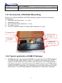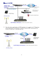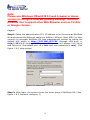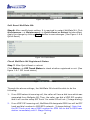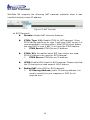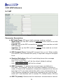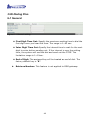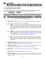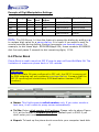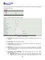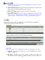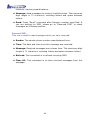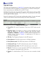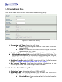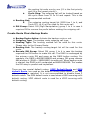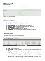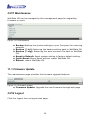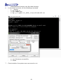
1
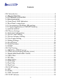
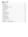
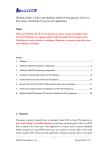
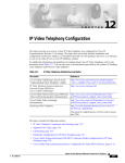
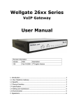
WellGate M4 GSM IP Gateway User Guide Version: 1.1 Date: December, 2014 Contents CH1 Introduction .................................................................................... 4 1-1 Physical Interface ............................................................................. 4 1-2 IP Network connection.................................................................. 4 1-3 Environmental ................................................................................ 5 1-4 Front Panel: LED Indicators ............................................................. 5 1-5 Rear Panel: connections.................................................................... 6 1-5-1 Accessories of WellGate M4 packing ........................................... 7 1-5-2 Typical application of GSM IP Gateway....................................... 7 1-6 QUICK SETUP ................................................................................ 9 CH2 Device Settings ............................................................................. 13 2-1 Network Configuration ................................................................... 13 2-2 Device Time Setting ....................................................................... 15 2-3 Device Advance Setting.................................................................. 17 2-4 User Login Setting .......................................................................... 18 2-5 Debug Settings ................................................................................ 19 2-6 Event Notice ................................................................................... 20 2-7 Auto Provision ................................................................................ 21 2-8 SNMP ............................................................................................. 22 CH3 NAT Setting ................................................................................... 24 3-1 DHCP Ser. (DHCP server).............................................................. 24 3-2 UPnP (universal plug and play server) ........................................... 25 3-3 Bandwidth (Bandwidth Control) .................................................... 25 3-4 URL Filter ....................................................................................... 29 3-5 IP Filter ........................................................................................... 29 3-6 MAC Filter ..................................................................................... 29 3-7 APP Filter........................................................................................ 30 3-8 Port Filter ........................................................................................ 30 3-9 Port Fwd ......................................................................................... 30 CH4 VOIP Setting ................................................................................. 32 4-1 SIP .................................................................................................. 32 4-2 Audio .............................................................................................. 33 4-3 NAT Traversal ................................................................................. 35 CH5 VOIP Advance .............................................................................. 36 2 5-1 SIP .................................................................................................. 36 5-2 Audio .............................................................................................. 39 CH6 Dialing Plan ................................................................................. 40 6-1 General............................................................................................ 40 6-2 Dialing Rule .................................................................................... 41 6-3 Digit Manipulation (DM) ............................................................... 42 6-4 Phone Book..................................................................................... 43 CH7 CO Setting .................................................................................... 45 7-1 CO line............................................................................................ 46 7-2 SMS ................................................................................................ 48 CH8 SIP Trunk ...................................................................................... 50 8-1 Create SIP Trunk............................................................................. 51 CH9 Route Plan .................................................................................... 54 9-1 Create Route Plan ........................................................................... 55 CH10 Status .......................................................................................... 57 10-1 Device Status ................................................................................ 57 10-2 Line States .................................................................................... 57 10-3 SIP Trunk Status ........................................................................... 58 CH11 Maintenance ............................................................................... 59 11-1 Firmware Update .......................................................................... 59 CH12 Logout......................................................................................... 59 Appendix A --- System Recovery ......................................................... 60 Appendix B --- HTTP auto provision ................................................... 62 3 CH1 Introduction WellGate M4 GSM SIP IP Telephony Gateway WellGate M4 is a 4 lines GSM (WellGate M4) VoIP gateway which includes 1-WAN and 1-LAN (management port) 10/100 base-T network environment. Field-proven quality of Voice communication and broadband access network to makes WellGate M4 to be an excellent solution for various VoIP applications with GSM network. 1-1 Physical Interface Ethernet port (RJ-45, 10/100 Base-T) 1-WAN port, for connect to router, ADSL modem (ATU-R), or switch hub directly as well as connect to SIP IP network. 1-LAN port, for PC management or other IP network devices connecting. Quad-band GSM module (850M 900M, 1800M and 1900M) DC power Jack +12Vdc LED indicate status Indicates Power, Ethernet, GSM Line, and system status 1-2 IP Network connection IPv4 (RFC 791)/IPV6 (RFC 2460) IPv6 Auto Configuration (RFC 4862) MAC Address (IEEE 802.3) Static IP DHCP Client (RFC 2131) PPPoE DNS Client TCP/UDP (RFC 793/768) RTP/RTCP (RFC 1889/1890) IPV4 ICMP (RFC 792)/IPV6 ICMP (RFC 4443) TFTP Client VOIP VLAN Support (802.1q/802.1p) HTTP/HTTPS Server QoS Support Support IPV4 only, IPV6 only or dual stack mode 4 1-3 Environmental Actual Dimension: 19-inch chassis, 1U high, 11 CM depth Weight: 2.3kg (One unit with packing) Operating Temp. & Humidity - Temp.: 0℃~45℃ (32℉~113℉) - Humidity: 10%~85% relative humidity, non-condensing Storage Temp. & Humidity - Temp.: 0℃~55℃ (32℉~131℉) - Humidity: 10%~95% relative humidity, non-condensing AC to DC Power Adaptor: - INPUT: AC100V-240V, 50/60Hz - OUTPUT: DC 12V, 3.0A Regulatory Compliance: FCC (Part 15, Class B) & CE 1-4 Front Panel: LED Indicators Figure 1-4-1 front panel LED Power Ready WAN LAN Description When the power adapter is connected, the Power LED will light up green. When system is startup successfully, the Ready LED will light up green. This Link LED will light up green when the gateway’s WAN port is physically connected to the public internet. When data is transmitted through this port, the Status LED will flash green. The default IP of WAN port is 10.1.1.3. This Link LED will light up green when the gateway’s LAN port is physically connected to a local network (Refer to Rear Panel section in page number for location of LAN port). When data is transmitted through this port, the 5 GSM 1 to 4 Status LED will flash green. The default IP of LAN port is 192.168.123.123. The status LED for GSM line 1-4. It will light up amber orange when the GSM line is engaged in a conversation. It will flash fast amber orange when there is an incoming call. GSM LED turns OFF when line is idle. ATTENTION: The LED of GSM line will flash slowly when the SIM card is not effective or SIM card was not inserted. 1-5 Rear Panel: connections Detachable antenna connector GSM Line 1. Follow this direction to insert SIM card. GSM Line 4. Figure 1-5-1 Connection rear panel for WellGate M4 Connect WAN port to SIP IP network. Attention: 1. Please turn OFF electric 12Vdc power when you want to remove or insert SIM card from WellGate M4. 2. Once you insert SIM card to WellGate M4 while electric 12Vdc is still ON, please visit webpage configuration at CO Line Select one CO Line ID (GSM) Reset GSM Module to reset it and activates this GSM feature. 3. To remove SIM card from card slot, simply press SIM card to eject and remove it from card tray. Item GSM Line 1 - 4 LAN WAN Description There are 4 slots to insert SIM card and detachable antenna connectors. 10/100 Base-T RJ-45 socket for LAN port, connects to PC for management purpose. 10/100 Base-T RJ-45 socket for WAN port, connects to 6 DC 12V SIP IP network. The power socket, input AC 100V~240V; output DC12V, 3A 1-5-1 Accessories of WellGate M4 packing When you receive WellGate M4 GSM packing, please check the following accessories. 1. WellGate M4 main units x 1 unit, 2. Antenna x 4 pcs, 3. AC to DC/3A Power adaptor x 1 pcs, 4. AC cable x 1pcs, 5. 19-inch chasses mount on Relay Rack brackets x 2 pcs. 5.Rack mounted brackets x 2 pcs. 2.Antenna x 4pcs 3.AC to DC +3A power adaptor x1 4.AC power input cable 1. WellGate M4 main units x 1pcs 1-5-2 Typical application of GSM IP Gateway 1. WellGate M4 can integrate with IP-PBX to connect with local PSTN network via GSM cellular base station (CBS). For legend connection with PSTN network, fixed land lines were often used. Therefore, one FXO gateway or E1 gateway needs to install between local PSTN network and IP-PBX office. Thanks to GSM IP gateway, the installation job is easier and more flexible than before. The following diagram indicates this connection example. 7 2. The alternative application of GSM gateway is to register to IP Telephony Service provider’s soft Switch in order to transit GSM incoming call to remote IP devices or international call. 8 1-6 QUICK SETUP Note: Please use Windows OS with IE 8.0 web browser or above version to configure GSM M4 gateway webpage. Welltech products don’t support other Web Browser such as FireFox or Google chrome. Login : Setp1: Setup the administrative PC’s IP address to be the same as WellGate M4 and connect the Ethernet cable into WAN or LAN port. Start IE8.0 (or later version) to navigate WellGate M4 web management system by typing the default URL which is http://192.168.123.123 (through LAN port) or http://10.1.1.3 (through WAN port). The screen will display User Name and Password (the default user id is root and user password is root). (See figure 1-6-1 web access) Figure 1-6-1 web access Step 2: After login, the screen shows the Home page of WellGate M4. (See figure 1-6-2 Network configure-1) 9 Figure 1-6-2 Network configure-1 Change Default IP Network: Step 3: After successfully login to the system, we need to change the network configuration. Click Device Setting --> Network to setup the service network interface (WAN) parameters. Enter the IP address, subnet mask and default gateway or selected to “DHCP” or “PPPOE”. Apply the change by clicking Apply button as figure below to save changes (See Figure 1-6-3 Network configure-2). Note: If Gateway WAN port was set up in the 10.x.x.x IP segment, please make sure to keep the LAN port IP segment as 192.168.x.x in order to avoid from conflicting between them. 10 Figure 1-6-3 Network configure-2 Change Default Time setting: Step 4: When re-login to the new IP address, the next step is to setup the system time zone. Click Device Setting --> Time to setup the system’s date and time. Enter the current NTP server, time zone and daylight saving parameters. Apply the change by clicking Apply button to save changes. (See figure 1-6-4 Time setting) Figure 1-6-4 Time setting Modify SIP Account Parameter: Step 5: The next step is to add a SIP trunk for VOIP calling. For WellGate M4, it is necessary for VOIP calling. Click SIP trunk and new to create the SIP trunk in details. Select one of 4 trunk ID and enter those SIP parameters. Apply the change by clicking Apply button to save changes. (See Figure 1-6-5 SIP Trunk) 11 Figure 1-6-5 SIP Trunk Soft Reset WellGate M4: Step 6: After modify basic setting. It is required to restart WellGate M4. Click Maintenance --> Maintenance --> Quick-Reset or Reboot to take effect. Apply the change by clicking Apply button to save changes. (See Figure 1-6-6 Quick-Reset) Figure 1-6-6 Quick-Reset Check WellGate M4 Registered Status: Step 7: After Quick-Reset or reboot. Click Status --> SIP Trunk Status to check whether registered or not. (See figure 1-6-7 SIP trunk status) Figure 1-6-7 SIP trunk status Through the above settings, the WellGate M4 should be able to do the following: 1. From GSM network incoming call, the caller will hear a dial tone which was generated from Wellgate M4. Then, the caller can dial a VOIP SIP number and it will use the setup SIP Trunk 1 to make SIP call out. (2 stage dialing) 2. From VOIP SIP incoming call, WellGate M4 designate GSM Line will be OFF hook and dial number to GSM BTS network. (1 stage dialing). Note that the SIP Trunk must carry DNIS number for GSM line to dial to GSM base station immediately with 1 Stage Dialing. 12 CH2 Device Settings From this setting category, all devices related parameters can be found here. 2-1 Network Configuration > Network Figure 2-1 network setting Parameter Description: Setting: IP Support: IPv6 or IPv4 stack to be supported. There are three options: IPv4 Only, IPv4/IPv6 or IPv6 Only. The default setting is IPv4. WAN Setting: WAN port was used to connect to SIP IP network. For instance, use WAN port to register to SIP soft switch, SIP Server or IP-PBX. Network Type: It supports Fixed IP, DHCP or PPPoE. IP Address: IP address to be entered if Fixed IP was selected. Default Gateway: Default gateway to be entered if Fixed IP was selected. DHCP Tag (option 60): To enter Vendor class identifier if needed. DHCP Tag (option 61): To enter Client identifier if needed. DNS Server1: Primary DNS Server IP address. DNS Server2: Secondary DNS Server IP address. VOIP VLAN: Enable VOIP VLAN or not. When this was enabled VOIP VLAN, the WAN port can be only accessed by VLAN. If it is required to 13 access webpage of WellGate M4, please use LAN port to access webpage configuration. VOIP VLAN ID(2-4096): The VLAN ID to be used if VLAN was enabled. Note: the default WAN IP address is 10.1.1.3. VOIP VLAN Priority (0-7): The VLAN priority to be used if VLAN was enabled. The number 7 has the highest priority. LAN Setting: Management mode: This LAN port is used for management purpose, not used for SIP register or network data routing. NAT mode: DHCP server is the function on the LAN port. The LAN port features DHCP server. If one computer network device was connected to LAN port, it will receive one IP address. IP Address: This is LAN port IP address. (Please set up 192.168.x.x IP address to LAN port if your WAN port is using 10.x.x.x IP segment in order to avoid from conflicting between them) Netmask: The subnet mask IP of LAN port. Bridge mode: At this mode, both WAN and LAN ports are configured to Switch/Hub features. When you want to access WellGate M4 via LAN port , please use WAN port IP address instead. Note: The default LAN IP address is 192.168.123.123 DDNS (DynDNS) Setting: DDNS (DynDNS): Enable or disable dynamic DNS feature. Domain Name: Enter Domain Name of DDNS Server. User Name: Enter your user name Password: Enter your password 14 2-2 Device Time Setting WellGate M4 supports NTP time server with time zone and daylight saving. Device Setting --> Time Figure 2-2 Time setting Parameter Description: Current Time: Show up current time and date. NTP Time Server: To enter NTP time server IP address. NTP Refresh Interval(sec): The interval time to synchronize NTP server time in seconds. Time Zone: The time-zone of WellGate M4 is located. It was indicated base on GMT+xx:yy or GMT-xx:yy. Daylight Saving: To enable daylight saving timer automatically or not. Daylight Bias: The offset added to the Bias when the time zone is in daylight saving time. Daylight Start: The date that a time zone enters daylight time. - Month: 01 to 12 - Week Day: Sunday to Saturday - Apply Week (Day:01 to 05, Specifies the occurrence of day in the month; 01 = First occurrence of day, 02 = Second occurrence of day, ...and 05 = Last occurrence of day) - Hour: 00 to 23 Standard Start: The date that a time zone go back from daylight time. - Month: 01 to 12 - Week Day: Sunday to Saturday 15 Apply Week (Day:01 to 05, Specifies the occurrence of day in the month; 01 = First occurrence of day, 02 = Second occurrence of day, ...and 05 = Last occurrence of day) - Hour: 00 to 23 - 16 2-3 Device Advance Setting --> Advance Figure 2-3 Advance setting Parameter Description: HTTP Service: The HTTP Web service port (the default is 80). HTTPS Service: The HTTPS web service port (the default is 443). Telnet Service: The telnet service port (the default is 23). HTTP/HTTPS Service access on WAN: When click the disable option, the WEB access will be rejected on WAN port. So please be careful with this function. If you wanted to enable WAN port again, you need to access this device from its LAN port to connect to WEB pages and enable WAN port. 17 2-4 User Login Setting Three levels of users login can be used. They are administrator, supervisor, and user. Each level of users has different predefined access level. -->User Login Figure 2-4 user login setting Parameter Description: Administrator: The administrator level user which has full access of WellGate M4. Supervisor: The supervisor level user which has limited administrative access right. User: The user access right which only allows to setting some user related features. User ID: Login User ID. Password: Login Password. Confirm Password: Confirm new password again. Language: The web page language used when the account login. To add a customized local language, please contact Welltech. 18 2-5 Debug Settings WellGate M4 provides the real time debug to syslog or through telnet interface. It generates the debug information based on debug level and modules. Since the generating debug consumes system resources, it is recommended to turn on only for debug period and under Welltech FAE’s instructions. Debug Figure 2-5 Debug setting Parameter Description: SYSLOG: Enable or disable to send system information to SYSLOG server or not Check for start from Any Time: Always send syslog at any time or only during a specified date/time range. Syslog Start (YYYY/MM/DD HH:MM): Send syslog at start Date and time. Syslog Stop (YYYY/MM/DD HH:MM): The syslog stop sending at Date and time. Syslog Server: Syslog server IP address. Syslog Port: Syslog server service port (default is 514). 19 DSP Debug: Enable or disable to send DSP information to capture log. DSP Capture server: Syslog capture server IP address. DSP Capture port: Syslog capture server service port (default is 50000) 2-6 Event Notice WellGate M4 can send Syslog Event Notice when it has the following cases: 1. Register Failure or re-registered. 2. SIM card is ready or not. 3. Ethernet reconnected. 4. System started. Figure 2-6 Event notice setting Syslog Notice: Enable or disable to send system event to SYSLOG server or not Syslog Server: Syslog server IP address Syslog Port: syslog server service port (default is 514) 20 2-7 Auto Provision -->Provision WellGate M4 offer configuration interface and allow manager to establish a HTTP auto provision server to configure this gateway automatically. Once you enable and select HTTP, the following fields are related to HTTP server security parameters. Figure 2-7-1 Provision Figure 2-7-2 Provision type of HTTP Server HTTP config URL: This field is to configure HTTP Server IP address and its path to store configuration parameters files. Refresh interval (minute): WellGate M4 will access HTTP provision server to check if there are new configuration/firmware to update according to this time interval in minutes. User ID: Specify the Login ID for HTTP server authentication. Password: Specify the password for HTTP server authentication. 21 2-8 SNMP WellGate M4 offers SNMP agent for central sites to manage and provision. Figure 2-8 SNMP SNMP Agent: SNMP Agent: Enable SNMP or not. Read Only Community Name: The community name to read through SNMP protocol Read Write Community Name: The community name to read and write through SNMP protocol. SNMP Agent Access on WAN: Enable SNMP to access through WAN port or not due to security reason. Trusted Peer: Type: Any Address: Any address can retrieve the SNMP information. Specify an IP Address: Only the designate IP address list here can retrieve the SNMP information. Normally, it will be the SNMP manger IP address. Specify a Subnet: Only the subnet network specified here can retrieve the SNMP information. IP address: The IP address for a trusted peer when you have specified IP address. 22 Subnet Mask: The network mask for a trusted peer when you specify an Subnet. SNMP Trap: SNMP Trap: Enable SNMP trap or not Destination: The IP address for SNMP manager to receive the SNMP trap Community: The community name for sending the SNMP trap 23 CH3 NAT Setting WellGate M4 can support NAT, 2 Ethernet ports (WAN and LAN) or Bridge mode. Here are the settings for NAT related services. 3-1 DHCP Ser. (DHCP server) Figure 3-1 DHCP server DHCP Server: Enable DHCP server or not at LAN port. Client Range Start IP: specify DHCP client lease start IP Client Range End IP: specify DHCP client lease end IP Default Gateway: specify the default gateway which is WellGate M4 IP address at LAN port. Submask: specify the subnet mask. DNS Server 1: specify the DNS server IP address. DNS Server 2: specify the DNS server IP address. 24 3-2 UPnP (universal plug and play server) Figure 3-2 UPnP To enable UPnP server or not. 3-3 Bandwidth (Bandwidth Control) By using bandwidth control feature, the user can manage the data traffic based on their needs. Figure 3-3-1 Bandwidth control Bandwidth Control: Bandwidth Control: enable bandwidth control or not. Download Bandwidth: specify total bandwidth for download (unit: kbps). 0 indicates no limitation. Upload Bandwidth: specify total bandwidth for upload (unit: kbps). 0 indicates no limitation. Maximum Bandwidth and Reserved Bandwidth: Setup Method: bandwidth control method, percentage or specify the required bandwidth Percentage: define percentage of total bandwidth to be used. priority 1: highest priority percentage priority 2: Normal priority percentage priority 3: low priority percentage 25 Figure 3-3-2 Bandwidth control Specific: define maximum and Reserved bandwidth in Kbps for download and upload. priority priority priority priority priority priority 1 2 3 1 2 3 – – – – – – Download: highest priority download bandwidth Download: normal priority download bandwidth Download: low priority download bandwidth Upload: highest priority upload bandwidth Upload: normal priority upload bandwidth Upload: low priority upload bandwidth Edit Control List: In order to set up which target is belonged to which priority, the following is the setting method for target’s priority. Figure 3-3-3 Edit control list IP Target Figure 3-3-4 IP Target 1 26 Figure 3-3-5 IP Target 2 Priority: Priority value for the target Type: The target type was set up to IP Configure Type: unique IP or a range of IP address Unique: IP Address: the IP address to be set IP Range: Start IP: The starting IP for a range End IP: The stopping IP for a range Port Target Figure 3-3-6 Port Target Priority: Priority value for the target Type: The target type is set to port number Configure Type: unique port number or a range of port number Unique: Port: the port number to be added Protocol: protocol for the port Port Range: Start port: the starting port number End port: the stop port number Protocol: protocol for the port range 27 Application Target Figure 3-3-7 Application Target Priority: Priority value for the target Type: Application Application: the list for the application DSCP target Figure 3-3-8 DSCP Target Priority: Priority value for the target Type: DSCP value DSCP: The DSCP will be mapped to the priority 28 WellGate M4 supports firewall features as follows. 3-4 URL Filter Figure 3-4 URL Filter URL Filter: the specified URL will be blocked. 3-5 IP Filter Figure 3-5 IP Filter IP Filter: The specified IP address to be blocked. Local IP address: The LAN side IP address to be forwarded. Protocol: TCP, UDP or both are used for port forward. 3-6 MAC Filter Figure 3-6 MAC Filter MAC Filter: The MAC address to be blocked. 29 3-7 APP Filter Figure 3-7 App Filter APP Filter: The application to be blocked. 3-8 Port Filter Figure 3-8 Port Filter Port Filter: enable port Filter or not. Port Range: Starting and stopping port to be forwarded. If you are using only 1 port, please set up the starting equal to stopping port. Protocol: TCP, UDP or both are used for port blocked. 3-9 Port Fwd WellGate M4 supports port forward feature as follows. Figure 3-9 Port Fwd 30 Port Fwd: enable port forward feature or not. Port Range: Starting and stopping port to be forwarded. If you are using only 1 port, please set up the starting equal to stopping port. Protocol: TCP, UDP or both are used for port forward. Local IP address: The LAN side IP address to be forwarded. Local Port: The LAN side port to be forwarded. If you are using the port range, this port indicates the starting port. 31 CH4 VOIP Setting 4-1 SIP Figure 4-1 SIP setting Parameter Description: Session Timer: Enable session timer or not (RFC 4028). Session Expires (sec): This is the setting of initial session timer expires time according to RFC4028 - Session Timers in the Session Initiation Protocol. Min SE (sec): The minimum session timer allowed when receiving a call with session timer value according to RFC 4028. PRACK: Enable provision ACK or not (RFC 3262) - None: Disable PRACK - Supported: When select this mode, the SIP command 100rel will be added to the support list to send to remote side. It indicates WellGate M4 can support the PRACK but not mandatory. - Require: PRACK is mandatory required. SIP Local Port: The SIP local service port (default is 8080) SIP QoS Type: Quality of Service Type for SIP signaling - None: Not using QOS Tag and not enables QOS. - DiffServ: Differentiated Services Value. Input DSCP value 0-63 for DSCP. - TOS: Type of Service which include IP precedence value and TOS. Accept Proxy Only: If you select YES, only accept the call coming from the registered SIP proxy. WellGate M4 Do Not accept peer to peer call at this mode, neither accept from different SIP proxy. This configuration prevent from hacker attacking. P2P call application: When you select NO at this option, this GSM 32 gateway can be configured to Peer to Peer mode. For P2P call, you also need to configure Phone book in order to dial remote site phone number to send IP address directly. Please refer to Chapter 6-4: Phone Book configuration. 4-2 Audio Figure 4-2 Audio setting Codec 1~5: The preferred codec priority while a call was established. The Codec 1 has the highest priority. While making a call, both termination devices will negotiate the priority Codec to be used to establish voice connection. The Voice Code Payload Size was indicated by time length. The talking voice was sent to SIP IP network according to your selected payload size (ms) and pack header/checksum in order to transmit over Ethernet IP network. The longer payload size time of voice codec was used, the less Ethernet IP bandwidth to consume. However, the side effect is the longer voice delay time at receiver side. In application, if the IP network has limited IP bandwidth, you had better to configure longer voice codec payload size (time) in order to reduce IP bandwidth. For instance, if you are going to talk via VSAT which has longer delay time, to select G.723.1 at 6.3kbps with 90ms payload size is the suitable one to provide acceptable voice quality. 33 G.711u Payload Size: G.711 u-Law payload size: 20ms and 40ms. G.711a Payload Size: G.711 A-law payload size: 20ms and 40ms. G.729 Payload Size: G.729A payload size: 20ms, 40ms, and 60ms. GSMFR Payload Size: GSMFR payload size: 20ms, 40ms, and 60ms. G.723.1 Payload Size: G.723.1 payload size: 30ms, 60ms, and 90ms. Bit Rate: G.723.1 bit rate used 5.3K bit rate is used 6.3K bit rate is used Codec Priority: Selection order to match the remote SDP for codec selection. Local SDP Order: Use local SDP order to match codec. Remote SDP Order: Use Remote SDP order to match codec. DTMF Relay: In-Band DTMF: use In-band DTMF instead of out-band. RFC 2833(fall back to SIP-INFO): Use RFC 2833 if the SDP negotiation could be done. Or use SIP INFO for DTMF relay. SIP INFO: Use SIP-INFO DTMF relay. RFC 2833(fall back to Inband): Use RFC 2833 if the SDP negotiation could be done. Or use inband DTMF transmission. Silence Suppression: Enable: Start the voice activity (silence) detection and send SID when detecting silence. Disable: Send silence packet as normal voice packet (no silence detection) RTP Basic Port: The RTP starting port. Each channel will be added additional 10. For example, the RTP basic port is 16384, therefore, call 1 will use 16384 while call 2 will use 16394 and etc. RTP QoS Type: IP QoS tag for RTP stream DiffServ: The differentiated service QoS tag will be used. Input DSCP value 0-63 for DSCP. TOS: Type of Service which include IP precedence value and TOS. 34 4-3 NAT Traversal WellGate M4 supports the following NAT traversal methods when it was installed behind private IP address. Figure 4-3 NAT Traversal NAT Traversal: Disable: Disable NAT traversal features. STUN (Type 1,2): Enable STUN for NAT traversal. Since STUN can be used only for type 1 and type 2 NAT server, it is recommended to use this option. When STUN client detect the used NAT is type 3 NAT, it will stop the STUN feature. STUN Server: STUN Server IP address STUN (All): No matter which NAT type server are used, STUN is always to be used for NAT traversal. STUN Server: STUN Server IP address UPNP: Enable UPnP client for NAT traversal. Please note that the IP sharing box need support UPnP feature. Behind NAT: Use DMZ for NAT traversal. IP Sharing Address: public IP sharing address. You need to specify the port mapping or DMZ for all required port. 35 CH5 VOIP Advance 5-1 SIP Figure 5-1 SIP Parameter Description: SIP Hold Type: SIP up on hold message sending method. - Send Only: Set the SDP media to send only when send an on-hold SIP message. - 0.0.0.0: Set up the SDP connection to 0.0.0.0 when send an on-hold SIP message. - Inactive: Set up the SDP media to inactive when send an on-hold SIP message. SIP Compact Form: Enable SIP compact form or not. When enable this feature, the connected SIP proxy is required to support compact form. Session Refresher: Who will send dialog keep alive message (re-invite or update). - UAC: User Agent Client will do the refresh (default setting) - UAS: User Agent Server will do the refresh. SIP T1 (msec): T1 determines several timers as defined in RFC3261. For example, when an unreliable transport protocol is used, a Client Invite transaction retransmits requests at an interval that start at T1 seconds and doubles after every retransmission. A Client General transaction retransmits requests at an interval that starts at T1 and doubles until it reaches T2. (Default Value: 500ms) SIP T2 (msec): Determines the maximum retransmission interval 36 as defined in RFC3261. For example, when an unreliable transport protocol is used, general requests are retransmitted at an interval which starts at T1 and doubles until reaches T2. If a provisional response is received, retransmission continue but at an interval of T2. (Default Value: 4000ms) SIP T4 (msec): T4 represents the amount of time the network takes to clear message between client and server transactions as defined in RFC3261. For example, when working with an unreliable transport protocol, T4 determines the time that UAS waits for after receiving an ACK message and before terminating the transaction. (Default Value: 5000) Invite Linger Timer: After sending an ACK for an INVITE final response, a client cannot be sure that the server has received the ACK message. The client should be able to retransmit the ACK upon receiving retransmissions of the final response for this timer. This timer is also used when a 2xx response is sent for an incoming Invite. In this case, the ACK is not part of the Invite transaction. General Linger Timer: After a UAS sends a final response, the UAS cannot be sure that the client has received the response message. The UAS should be able to retransmit the response upon receiving retransmissions of the request based on this timer. Cancel General No Response Time (msec): When sending a CANCEL request on a General transaction, the User Agent waits for cancel General No Response Timer milliseconds before timeout termination if there is no response for the cancelled transaction. (Default Value: 10000ms). General Request Timeout Timer (msec): After sending a General request, the User Agent waits for a final response general Request Timeout Timer milliseconds before timeout termination (in this time the User Agent retransmits the request every T1, 2*T1,…T2,…milliseconds). Cancel Invite No Response Timer (msec): When sending a CANCEL request on an Invite request, the User Agent waits for this timer before timeout termination if there is no response for the cancelled transaction. Provisional Timer (msec): The provisionalTimer is set when receiving a provisional response on an INVITE transaction. The transaction will stop retransmissions of the INVITE request and will wait for a final response until the provisionTimer expires. If you set up the provisionTimer to 0, no timer is set. The INVITE transaction 37 will wait for indefinitely for the final response. First Response Timer (msec): When sending a request out, the User Agent waits for this timer for any response received from UAS. If timer is expired and not any SIP message is received, the User Agent will think the request is failed. The default is 5 seconds. Line Congestion Code: When callee's end system was contacted successfully but the callee is busy and does not wish to take the call at this time, the system wills response the code, default is 600. 38 5-2 Audio The setting page includes the device related audio settings. Figure 5-2 Audio setting RFC 2833 Payload Type: 96 or 101. It is recommended to use 101. DTMF Send On Time(msec): When generate DTMF, the DTMF on time will be sent (default time is 70 ms) DTMF Send Off Time(msec): When generate DTMF, the DTMF OFF time between two digits will be sent (default time is 70 ms) DTMF Detect Min on Time (msec): The minimum DTMF ON time will be recognized as a regular DTMF event. Less than this time will be ignored. The default value is 60ms. DTMF Detect Min off Time (msec): The minimum DTMF OFF time between two digits to recognize. Less than this time, the next DTMF digit will be recognized as the same previous one. It will be handled as one digit only instead of two digits. DTMF Relay Volume: The DTMF relay volume in dBm. Min Jitter Buffer (msec): The minimum delay time of Jitter buffer. Max Jitter Buffer (msec): The Maximum delay time of Jitter buffer. Max Echo Tail Length (G.168): Enable the echo cancellation feature. The default setting is 128ms. Jitter Opt. Factor: Jitter buffer dynamic factor for optimize. Please set to 7 unless under Welltech’s instruction to change. 39 CH6 Dialing Plan 6-1 General Figure 6-1 General setting First Digit Time Out: Specify the maximum waiting time to dial the first digit once you hear dial tone. The range is 1~60 sec. Inter Digit Time Out: Specify the interval time to wait for the next digit to enter before sending out. If the interval is over the setting time, the system will end the dial and send out the DTMF. The limitation range is 1~10sec. End of Digit: The assigned key will be treated as end of dial. The factory default key is “#”. Retrieve Number: This feature is not applied to GSM gateway. 40 6-2 Dialing Rule Figure 6-2 Dialing Rule setting Dialing rule is used to speed up the dialing procedure while you have dialed complete digits. Some users don’t like to use the end of dialing digit such as # key, this GSM gateway can be configured to use dialing rule instead. The longest digits of prefix code will be selected first if it was matched. Dialed Prefix: The prefix code to be matched. Max Digits: The digits will be received based on the Dialed Prefix code and the following number. The following is an example for dialing rule: Mobile call start with prefix: 09, and it is 10 digits length. Long distance call start with prefix: 0, and it is 10 digits length. International call start with prefix: 00, and its max digit should be less than 32 digits. The others are local call (city call) with 8 digits maximum length. Emergency call start with prefix: 1 and 3 digits, and its maximum digit is 3 digits length. The Dialing Rule setting can be configured as follows: Dial Prefix number 09 0 00 1 9 2 3 4 5 6 7 8 Maximum digit length 10 10 15 3 3 8 8 8 8 8 8 8 41 Remarks Mobile call Long distance call International Call Emergency Call Emergency Call City Call City Call City Call City Call City Call City Call City Call 9 8 City Call 6-3 Digit Manipulation (DM) The Digit Manipulation is to define outgoing call rule and will be processed based on prefix code and DM group after the DNIS is determined. Figure 6-3 Digit Manipulation setting DM Group: Different DM group have different dial plan to be used. There are six DM groups to be configured. GSM: This DM group describes GSM incoming call and will route to next receiver. It is used for GSM 2 stage dialing only. After the DNIS is collected (dialing number), this DM group will be processed before entering the dial out routing procedure to VoIP SIP Trunk. VOIP: This DM group is used for VOIP incoming call and route to GSM outgoing call. After the DNIS (the name dial to GSM line) was collected in 1 stage dialing DNIS, this DM group will be processed before entering the routing procedure. 1-4: These DM groups are used for backup routing purpose. When a backup routing is used, the administrator can select a DM group to be processed before starting the backup outgoing route call. Matched Prefix: The prefix to be matched for DM. The longest prefix digits will be selected first to check if it is matched. Matched Length: Set to 0 for ignoring the length. The other 1-32 digits length are the length to be matched as a condition. Start Pos: The next digit of start digit position to be replaced. Stop Pos: The stop digit position to be replaced. Replace Value: First, the next digit position of start digit position until stop digit position will be removed. Then replaces with the Replace Value. 42 Example of Digit Manipulation Settings: Prefix Length Stop Pos 0 0 5 Replace Value 002 002 002 Before DNIS Result DNIS 0 12 0 Start Pos 0 0 2 886 886 886 8862123456 8862123456 8862123456 0028862123456 8862123456 8800223456 886 0 30 30 002 8862123456 8862123456002 886 0 1 6 8862123456 83456 Note: The DM Group 1~4 has the feature to pause the dialing by adding a p to replace digit value for a pause dialing. It is useful if you want to wait for several seconds during dialing. Each p represents one seconds pause. For example, to dial these digit: 822265699ppp1234; these numbers 82265699 dial first and pause 3 seconds to dial remaining digits, 1234. 6-4 Phone Book Phone Book is used to send out SIP IP peer to peer call from WellGate M4. The limitation of maximum phone book is 100 records. Attention: When WellGate M4 was configured to P2P call, the SIP IP incoming call to GSM outgoing call only supports one stage dialing. It means that the SIP IP incoming call should carry GSM destination number (PSTN number). Figure 6-4 Phone Book setting Name: This field supports called number only. If you enter words or text here, it will routes to proxy server automatically. Tel No: Enter called number @ IP address. Please refer to above Figure 6-4, at the format of number@uri:port. (default port is 5060 if you don’t enter port number.) Export: To back up the phone book records to your computer hard disk. 43 Import: To reload setting of phone book from your computer hard disk. 44 CH7 CO Setting The CO Line setting contains the GSM related parameters and SMS. Figure 7-0 CO setting Line ID: There are four GSM lines. Line ID indicates one of them (GSM 1 to GSM 4). State: The GSM line is active or inactive. TEL No: The reference telephone number (e.g. SIM Card number). Hotline TEL: This feature is used for GSM incoming call and route to SIP IP Trunk with telephone number automatically. If hot line is configured, this field shows the hot line number. AT P2P application, “Hotline TEL” should fill in receiver’s IP address. If receiver device has different SIP port number as 5060, then the port number should be added after IP address. For instance, the receiver IP is 192.168.2.1 and SIP port is 8088, then this field should be 192.168.2.1:8088. 45 7-1 CO line Select left icon from CO Line webpage to enter GSM Line configuration page as following RED box. Here is “modify GSM line setting” page. Figure 7-1 CO setting Line ID: There are four GSM lines. Line ID indicates one of them (L1 to L4). Line Type: The line type is GSM. Line State: To activate if you would like to use this line. Otherwise, inactive to disable this line. TEL NO: This field can be used as a reference remark for this GSM SIM number. Normally, you can put the connected SIM card number here for reference. Incoming call handling: The call handles policy for a GSM incoming call. Hot line TEL: When a GSM incoming call was detected, GSM Gateway will send the SIP call to the specified hot line TEL 46 number through the Route Plan. 2 Stage Dialing: When GSM incoming call was detected, GSM Gateway will answer it and play the dial tone(if “Play Voice File” command was not activated) for 2 stages dialing to VOIP. Playback voice file: To enable playing voice greeting file to caller or not when GSM incoming call was configured to 2 Stage Dialing. Repeat Count: Repeat how many times to play voice greeting file during 2 Stage Dialing. Voice file name (voice file format: Mu-Law, Mono, 8K): Specify the file path and file name to upload in order to play Voice greeting file while there is GSM incoming call. Please make sure that your recorded greeting file format needs to be G.711u/Law, Mono, 8K, 8 bits raw file. Attention: How to record your own greeting file ? WellGate M4 doesn’t provide any tool for you to record your own greeting file. You may use computer with recording program and install external microphone to record. If you have existing greeting file, you may need to use recording program to covert to G.711u-Law, Mono, 8K and 8 bits file format. The recorded greeting file time should not be more than 15 seconds. Otherwise, the file size is too big to upload WellGate M4. Input(Encode)Gain: Adjust the volume from GSM to VOIP (default is 0 dB). Output(Decode)Gain: Adjust the volume from VOIP to GSM (default is 0 dB). PIN Code: enter the PIN code to activate the SIM Card. Unlock SIM Card: enter the PUK code to activate the SIM card when the SIM card was locked. The PUK code was given by your service GSM operator company. Call Time Quota (sec): You can define accumulation maximum talk time at each GSM line in order to restrict call out time in seconds via GSM. If the total talk time was over this value, M4 GSM gateway will reject making call out from GSM port while there is incoming call from IP side. (If the call time was over the limit seconds during talking 47 period, the call can continue. M4 GSM gateway will reject call out at the next call attempt.) Total Call Time (sec): To show the accumulated talk time which had been calling out from this GSM port up to now. Clear Call Time: Reset/Clear the Total Call Time to zero. Reset GSM Module: If the SIM card was plugged in to that GSM line while power is already ON at WellGate M4 gateway, Please click “Reset” button to that GSM line in order to activate GSM module. 7-2 SMS Select right icon from CO Line webpage to enter SMS (short messages) configuration page as following RED box. Here is sending and receiving SMS message webpage. Send SMS: This row is used to fill in destination number and message to be sent. Line ID: There are four GSM lines. Line ID indicates one of them (GSM 1 to GSM 4). Receiver: This field is used to dial number to GSM. This number can be receiver’s PSTN number or Mobile operator’s service code. For 48 instance, inquire prepaid balance. Message: Send messages to receiver’s mobile phone. The maximum digit length is 70 characters including letters and space between letters. Send: Press “Send” command after Receiver number was filled. If you are waiting for SMS, please go to “Received SMS” to check messages as following section. Received SMS: This row is used to read message which you have received. Sender: The sender phone number was displayed here. Time: The date and time once this message was received. Message: Received messages were shown here. The maximum digit length is 70 characters including letters and space between letters. Refresh: This command is to refresh incoming SMS. Clear All: This command is to clear received messages from this webpage. 49 CH8 SIP Trunk SIP Trunk (the physical port is WAN RJ-45 connector) was used to make call from GSM line to SIP IP network to remote device, or receive incoming call from remote device to WellGate M4 via SIP IP Trunk. WellGate M4 needs to be set up the SIP trunk for VOIP outgoing call from GSM line and incoming call from SIP Trunk to GSM line. There are up to 4 SIP trunk can be used for whole system. Figure 8-0 shows four SIP Trunk major configuration status. You can click each Trunk to enter details contents and modify your desire parameters. Figure 8-0 SIP Trunk page Trunk ID: SIP trunk ID selection. There are 4 SIP Trunks can be used. Register Type: This feature is used to connect WellGate M4 with other SIP devices or SIP Server. Register type has two modes: Predefine or Register. Predefine is used to connect to SIP Server or IP-PBX directly, however, Register is registering to SIP Server or IP-PBX as a Gateway. TEL No: The Telephone Number for the SIP account. Proxy Server: The SIP proxy server or IP-PBX IP address. Proxy Server port: The SIP proxy server or IP-PBX port. Outbound Proxy: The SIP outbound proxy server IP address. Outbound Server Port: The SIP outbound proxy server port. Export: To back up or copy out these 4 SIP Trunk configurations to your computer’s hard disk as SIP Trunk File. Import: To reload setting of SIP Trunk from your computer stored file. 50 8-1 Create SIP Trunk Figure 8-1 SIP Trunk page Trunk ID: SIP trunk ID. Register Type: Whether this account need register or not. Register: When it was set up to register, WellGate M4 will send REGISTER message to SIP proxy server (or IP-PBX server) for registration. Predefine: When it was set up to predefine, WellGate M4 DO NOT send REGISTER message to SIP Proxy server (or IP-PBX). Domain: This field was used for Register Only (not for Predefine mode). The Domain name of SIP proxy server can be entered IP address to make call via SIP Trunk. Proxy Server: SIP registrar server or IP-PBX server IP address for WellGate M4 to register. Proxy Server Port: SIP registrar server port number. Outbound Proxy Server: outbound proxy server IP address. Outbound Proxy server port: outbound proxy server port number. Register Expires: the default register time expired during registration negotiation. TEL No: The registrar telephone number. 51 User ID: The SIP user ID was used for registration and making a call. User Password: The SIP password was used for registration and making a call. Display Name: The SIP display name. Reject Anonymous Call: Reject the anonymous incoming call from SIP Trunk. Outgoing Caller ID: The outgoing call to SIP Trunk caller ID mode contains two fields, Display Name and User ID. - Display Name: The display name will be set up according to the following type. None: The display name doesn’t send in caller ID format. PSTN caller ID: The PSTN caller ID from GSM line is used as display name. SIP display name: The “Display Name” field of SIP Trunk will be used as SIP display name for outgoing call. GSM Tel NO: The GSM SIM card phone number of incoming GSM line will be used as SIP display name for outgoing call. - User ID: The SIP caller ID will be used according to the following type. SIP user ID: If the SIP user ID is set, the SIP user ID set in this SIP trunk will be used and the domain/SIP proxy will be the host part. The SIP FROM header’s URL will be the SIP_User_ID@Domain or SIP_User_ID@SIP_Proxy_Server. PSTN caller ID: If the PSTN caller ID will be used in SIP URL, the SIP FROM header’s URL will be PSTN_Caller_ID@local_IP_address. GSM TEL NO: If the GSM SIM card Telephone number will be used in SIP URL, the SIP FROM header’s URL will be GSM_Tel_NO@local_IP_address. Attention: The following guideline could be used for the most application cases: 1. If the WellGate M4 was registered at SIP proxy or IP-PBX and was configured as a gateway, Please enter “PSTN caller ID” at both Display Name and Caller ID field. 2. If the WellGate M4 was registered at SIP proxy or IP-PBX and was configured as a subscriber, Please enter “SIP User ID” at both Display Name and Caller ID field 52 Keep Alive: Enable or Disable it. Keep Alive Time (sec): Specify of times in second to send SIP register message to proxy server or IP-PBX. For DNIS is Registered TEL: This feature was used for SIP Trunk incoming call and outgoing to GSM line. The current firmware version only provides 1 Stage Dialing selection. The 2 Stage Dialing isn’t available at present. 53 CH9 Route Plan The core of WellGate M4 is the routing policy. The policy is based on incoming call type/target, length and prefix to determinate the outgoing call process. For VOIP incoming call, it can send to GSM interface and vice versa. Figure 9-0 Route Plan page Incoming Call Type: Incoming call type (GSM or VOIP) Matched Prefix: matched DNIS incoming (called number) prefix Matched Incoming List: matched DNIS incoming interface target Matched Length: matched DNIS incoming digit (called number) length. Outgoing Type: The incoming call (GSM or VOIP) was routed to outgoing call type (GSM or VOIP). 54 9-1 Create Route Plan Click Route Plan and Click new to create a new routing policy. Figure 9-1 Route Plan setting Incoming Call Type: Incoming call type VOIP: The incoming call from SIP Trunk VoIP. It can only route to GSM. GSM: The incoming call from PSTN GSM type. It can only route to VOIP SIP Trunk. Matched Prefix: matched DNIS incoming (called number) prefix. Matched Incoming List: matched DNIS incoming GSM Lines. This command is not applied to VOIP SIP Trunk incoming call. Only the GSM call is coming from the selected line (GSM Line 1 to Line 4) will be accepted for this route plan. Matched Length: matched DNIS incoming call digit (called number) length. To ignore the length, please set up to 0 (zero). No Answer Timeout: How long the hunting will continue to next incoming call when the called target doesn’t answer. Create Route Plan>Primary Route Outgoing Type: Outgoing call type (GSM or VOIP) Hunting Type: The hunting method (how to select one GSM line or SIP Trunk) will be used for this route call. Priority Ring: The outgoing call will be hunted based on 55 the routing list order one by one (01 is the first priority and 04 is the lowest priority). Cyclic Ring: The outgoing call will be hunted based on the cyclic basis from 01 to 04 and repeat. This is the recommended method. Routing List: The outgoing routing target list (GSM Line 1 to 4, and Trunk ID 1 to 4) will be used for this route call. DM Group: Select DM (Digit Manipulation) group 1 to 4 in case it requires DM to remove the prefix before making the outgoing call. Create Route Plan>Backup Route Backup Route Active: Activate the backup route or not. Outgoing Type: The backup route outgoing call type. Hunting Type: The hunting method will be used for this route. Please refer to the Primary Route. Routing List: The backup routing target list will be used for this route. Reroute DM Group: Select DM group 1 to 4 in case the backup required the DM before to make the call. The DNIS is unchanged by the primary route DM and same as the DNIS before routing. For example, the DNIS is 886282265699 and primary DM group remove 886 and use it (DNIS = 282265699) to make call. When backup route is started, the DNIS is still unchanged as 886282265699. This makes the DM easy to predict and implement. There are two special default routes, VOIP Default Route and GSM default Route, are used as the default routing when there is not any other routing are matched. It is not recommended to disable these 2 default routes. The GSM default route is used when a GSM incoming call’s default routing. VOIP default route is used for a VOIP incoming call’s default routing. 56 CH10 Status WellGate M4 shows out the current system status here. Figure 10-0 Device Status 10-1 Device Status See the figure 10-0 Device Status Model: The model number, WellGate M4. MAC-Address: The MAC address of WellGate M4 Network Type: The Network Interface Type Settings IP-Address: IP address is using IPV6 IP-address: display IPV6 address Firmware: The firmware version and release information 10-2 Line States This page shows each line’s current status. Figure 10-2 Line Status Line: L1 to L4 of GSM. Call State: The Line status for this GSM line, Not Connected, Busy or Idle. Not Connected Reason: SIM Busy (Not SIM card or invalid) RSSI: This shows the Received Signal Strength Indicator of the current GSM cell. The range is from 0 to 31 which represent a signal level ranging from -113 dBm to -51 dBm. Each increment in RSSI values means 2 dBm increments. The 99 means that the signal level 57 is unknown or undetected. IMEI: It indicates International Mobile Station Equipment Identity. Which is a number, usually unique to identify 3GPP (i.e., GSM, UMTS and LTE) and iDEN mobile phones, as well as some satellite phones. IMSI: It shows International Mobile Subscriber Identity which is used to identify the user of a cellular network and is a unique identification associated with all cellular networks. It is stored as a 64 bit field and is sent by the phone to the network. Remain: display the remaining time if the Call Time Quota was configured. Once the Total Call time (accumulated call time) equal to Call time Quota (Remaining time reaches zero), the corresponding GSM line is locked and stop dial digit to PSTN network at the next call attempt. 10-3 SIP Trunk Status Figure 10-3 SIP Trunk Status Account: SIP trunk account number. Registered: The SIP trunk register status. Concurrent Call: How many concurrent calls are using this SIP trunk now. Refresh Interval (second): The interval time to refresh the status. 58 CH11 Maintenance WellGate M4 can be managed by this management page for upgrading firmware or reset. Figure 11-0 Maintenance Backup: Backup the system settings to your Computer for restoring purpose. Restore (*.ini): Restoring the backup setting back to WellGate M4. Restore (*.cfg): Restoring the auto provision file back to WellGate M4. Reset to Default: Reset system setting to factory default setting. Quick-Reset: Warm Reset without reboot WellGate M4. Reboot: reboot WellGate M4. 11-1 Firmware Update This maintenance page provides the firmware upgrade features. Figure 11-1 firmware update Firmware Update: Upgrade the new firmware through web page CH12 Logout Click the Logout item to logout web page. 59 Appendix A --- System Recovery WellGate M4 use dual firmware image to ensure the system stabilities. In most cases, you will not encounter the system failed to boot issue. Normally, the user should be able to use Web page to login and upgrade the firmware through it. If you are not able to do it, please follow the following steps for recovery. 1. 2. 3. 4. 5. Start the WellGate M4 and to check the STATUS LED is up or not. If STATUS LED is ON, please press the reset button for 5 seconds to reset to default. After all LED are light up, the system is back to factory settings. Change your PC IP address to 192.168.123.111 and network set to fix IP address mode. Connect your PC to LAN port and use http://192.168.123.123 to upgrade the firmware. Make sure you are using Microsoft IE 8 or above version. Do not support FireFox or Google Chrome Web browser. If you cannot login to the web page through 192.168.123.123. Open a command line from windows and type “telnet 192.168.123.123”. If you can see the following display, go to the next step. Otherwise, please contact Welltech FAE for RMA (Repair) procedure. Prepare a TFTP server for firmware download as follows download tftp server http://www.welltech.com/support/voip/TFTP/TFTP_Server.zip or http://tftpd32.jounin.net/tftpd32_download.html - start tftp server 60 6. download the firmware into tftp data directory In the telnet terminal, do the following command 1. __dmctw 2. cd /config_fs 3. rm -f wg26*.bin 4. tftp –g –r wg26.1.01_1DSP_1.0.bin 192.168.123.111 7. 4. copy firmware successfully 5. reboot Check whether the system was recovered or not 61 Appendix B --- HTTP auto provision Get the http provision packet from Welltech and start the provision as follows: Step 1: build mac list for mass configuration file generation For GSM> WellGate M4 MAC.csv contains most frequent changed parameters as follows: MACAddress: WellGate M4 MAC Address Siptk1.displayname ~ siptk4.displayname: display name for each GSM line. Siptk1.userid ~ siptk4.userid: user id for register to SIP proxy for each line siptk1.password ~ siptk4.password: user password for register to SIP proxy of each GSM line Siptk1.telno ~ siptk4.telno: tel no for each line Please save and close it. Step 2: create a template configuration file Open the “WellGate M4 Parameter.txt” getting from Welltech and make the required change. Please at least make the changes for those settings from provision and SIP proxy. For detail, please refer to the comments of “wgM4 Parameter.txt”. Step 3: Make the change for wegencfg.ini as follows if necessary # Template File BaseFile=.\Wellgate M4 Parameter.txt # MAC list file ListFile=.\Wellgate M4 MAC.csv # 0: Off, 1: On Encrypt=0 Step 4: Generate the individual configuration file. Double click the “wtgencfg.exe”, it will generate the configuration file for each MAC list in “MAC address.cfg” as the following pictures. 62 Step 5: Put the “*.cfg” file into http or ftp directory. Set up the provision settings in WellGate M4 and reboot to test it. You can use the hfs for http file server. It can be downloaded from http://www.rejetto.com/hfs/. Note: please link it to download provision file. More information please refer to “wgM4 Parameter.txt”. http://www.welltech.com/support/voip2/SIP%20series/FXSO%20series/M4/ Provision.zip 63