1
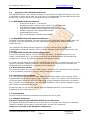
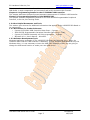
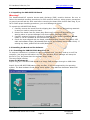
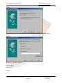
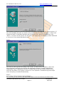
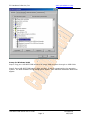
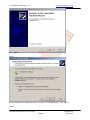
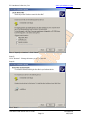
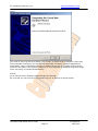
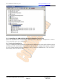
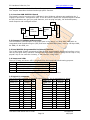
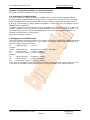
PC Hardware & Service, Inc
www.pchardwares.com
USB 8255 DIO User Manual
General Purpose Digital IO Board
Version:
Author:
Email:
Date:
1.0
Yan Wang
[email protected]
August 22, 2002
USB 8255 DIO Board User’s Guide
Page 1
Confidential
08/23/02
PC Hardware & Service, Inc
www.pchardwares.com
PC Hardware & Service, Inc.
1124 Somerset Dr.
San Jose, CA 95132
Phone: 408.272.5568
FAX:
408.272.5568
If you have comments or suggestions about this manual or find any errors in it, please contact
us at [email protected].
For technical support, contact us using any of the following methods:
Phone: 408.272.5568
FAX:
408.272.5568
E-mail: [email protected]
PC Hardware & Service, Inc. also maintains the following web sites:
http://www.pchardwares.com
Contains product information, technical notes, support files available for
download, and answers to frequently asked questions (FAQ).
ftp:// ftp.pchardwares.com
Contains technical notes and support files. Login as "anonymous" and use your
e-mail address for the password.
USB 8255 DIO User Manual
Version 1.0
© 2001 PC Hardware & Service, Inc
All Rights Reserved
The information in this manual has been carefully checked and is believed to be accurate and
reliable. However, PC Hardware & Service, Inc. assumes no responsibility for any inaccuracies,
errors, or omissions that may be contained in this manual. In no event will PC Hardware &
Service, Inc. be liable for direct, indirect, special, incidental, or consequential damages
resulting from any defect or omission in this manual. PC Hardware & Service, Inc. reserves the
right to revise this document and to make changes from time to time in the content hereof
without obligation of PC Hardware & Service, Inc. to notify any person or persons of such
revision or changes.
Intel is a registered trademark of Intel Corporation.
Cypress is a registered trademark of Cypress Corporation.
Microsoft, Windows, and Windows NT are registered trademarks of Microsoft Corporation.
All other products are the trademarks or registered trademarks of their respective holders.
Printed in the USA
August 22, 2002
USB 8255 DIO Board User’s Guide
Page 2
Confidential
08/23/02
PC Hardware & Service, Inc
www.pchardwares.com
Chapter 1 Introduction
1.1 Overview of the USB 8255 DIO Board ....................................
1.1.1 USB 8255 DIO Board Features .............................................
1.1.2 USB 8255 DIO Board System Architecture .............................
1.1.3 USB 8255 DIO Board Software Architecture ...........................
1.2 About this User’s Guide................................................................
1.2.1 Purpose of this Document ...............................................
1.2.2 Conventions ..................................................................
1.2.3 Chapter Overviews .........................................................
1.3 Other Helpful Documents and Tools..............................................
1.3.1 Documents for Further Reference ..................................
1.3.2 Software Development Tools ........................................
Chapter 2 Preparing the USB 8255 DIO Board for Operation
2.1 Unpacking the USB 8255 DIO Board ..........................................................
2.2 Installing the Board and Its Software......................................................
2.2.1 Installing the USB 8255 DIO Board in a PC...................................
2.2.2 Installing the USB 8255 DIO Windows Example Source Code...........
2.3 Testing the Installation ..........................................................................
Chapter 3 Overview of the Hardware Components
3.1 Overview USB 8255 DIO Board..........................................
3.2 Cypress CY7C63001 USB Controller..........................................
3.3 Intel 82C55A Programmable Peripheral Interface.......................
3.4 Jumps and LEDs....................................................................
3.5 Digital IO connector............................................
Chapter 4 Programming Details for the CY7C63001 USB Controller
4.1 Overview of the CY7C63001 USB........................................................
4.2 Function of the CY7C63001 USB.......................................................
Chapter 5 Programming Details for Intel 82C55A PPI
5.1 Overview of the 82C55A PPI.......................................................
5.2 Registers of the 82C55A PPI...................................................
Chapter 6 USB 8255 DIO Board Programming
USB 8255 DIO Board User’s Guide
Page 3
Confidential
08/23/02
PC Hardware & Service, Inc
www.pchardwares.com
Chapter 1 Introduction
1.1
Overview of the USB 8255 DIO Board
The USB 8255 DIO is a cost efficient and easy to use solution for Digital IO industry. One side
of the board is a play & play USB, the other side is a programmable 24 bits digital IO that was
divided into 3 ports, each port’s working mode can set individually.
1.1.1 USB 8255 DIO Board Features
•
Universal Serial Bus 1.1 Connection
•
No dedicate power needed, power comes from the USB cable
•
Intel 82C55A Programmable Peripheral Interface chip
•
Programmable 24Bits(3 Ports) Digital IO, each port has 8 bits
•
Industry standard 50 Pin Digital IO connector
•
Windows98/2000 drivers
•
Easy to use Windows example source code
1.1.2 USB 8255 DIO Board System Architecture
Following is the board diagram, Host use the differential USB signal communicating with USB
controller, Host can read/write the 12bit GPIO and generate 82C55A mode setting and
read/write time.
The USB 8255 DIO board includes Cypress CY7C63001 USB controller, Intel82C55A
programmable peripheral interface, 50-pin industry standard Digital IO connector and a test
jump/LED.
1.1.3 USB 8255 DIO Board Software Architecture
For the end user who want to use the USB 8255 DIO board, the development tool is very
simple, just Microsoft VC++, the board comes with the windows98/2000 drivers and some
example VC++ source. The software architecture diagram is below:
For some user who wants to change the USB 8255 DIO function, you need more tools, such as
Cypress CY7C63001 assembly compiler, chip programmer for USB controller firmware and
Windows98 DDK and WinDK for Windows Driver development.
1.2 About this User’s Guide
This section provides an overview of each chapter’s content, and it describes certain variations
in text and naming conventions we have used throughout the manual.
1.2.1 Purpose of this Document
This user’s guide covers hardware of the USB 8255 DIO Board board, which supports 24 Bit
programmable Digital IO through an easy to use USB 1.1 port. The purpose of this document is
to provide details about the USB 8255 DIO Board ’s major hardware components, to describe
how to install and properly operate the USB 8255 DIO Board, and to discuss important issues
that relate to programming the board.
We assume that you are already familiar with the Windows operation, and some basic
programming skill of Microsoft VC++.
1.2.2 Conventions
We have used the following conventions throughout this user’s guide.
1.2.3 Chapter Overviews
Chapter 2: Preparing the USB 8255 DIO Board for Operation
This chapter describes the tasks that you must perform to prepare your board for installation,
install the software for the board, install the board, and test the installation.
Chapter 3: Overview of the Hardware Components
USB 8255 DIO Board User’s Guide
Page 4
Confidential
08/23/02
PC Hardware & Service, Inc
www.pchardwares.com
This chapter discusses the board’s architecture, and also shows the location of the USB 8255
DIO Board ’s major components and connectors and briefly discusses their function.
Chapter 4: Programming Details for the CY7C63001 USB Controller
This chapter discusses the board’s most important comportment CY7C63001 USB Controller.
Chapter 5: Programming Details for Intel 82C55A PPI
This chapter provides programming details for the Intel 82C55A Programmable Peripheral
Interface, to set the port-working mode.
1.3 Other Helpful Documents and Tools
This section gives sources for additional information that applies to the USB 8255 DIO Board or
its components.
1.3.1 Documents for Further Reference
•
Cypress CY7C63001 USB Controller Data Sheet – Cypress.
•
Intel 82C55A Programmable Peripheral Interface Data Sheet – Intel.
•
Cypress CY7C6300X Assembly and Chip programmer – Cypress.
•
Microsoft VC++ User’s Manual – Microsoft.
1.3.2 Software Development Tools
Windows Application examples of The USB 8255 DIO Board are Microsoft VC++ Code, the
firmware code inside the USB controller is assembly. As user windows application call only the
Windows driver, it is not necessary to learn the USB RISC assembly unless you are going to
change the USB board function or make your own USB device.
USB 8255 DIO Board User’s Guide
Page 5
Confidential
08/23/02
PC Hardware & Service, Inc
www.pchardwares.com
Chapter 2 Preparing the USB 8255 DIO Board for Operation
2.1 Unpacking the USB 8255 DIO Board
Warning!
The Hammerhead-PCI contains electro-static discharge (ESD) sensitive devices. Be sure to
follow the standard handling procedures for ESD sensitive devices, taking proper precautions
to ground yourself and the work area before removing the board from its anti-static bag. If you
fail to follow proper handling procedures, you could damage the board.
To unpack the USB 8255 DIO Board,
1. Carefully remove the board from the shipping box. Save the box and packing materials
in case you need to reship the board.
2. Remove the board from the plastic bag. Observe all precautions described in the
warning above to prevent damage from electro-static discharge (ESD).
3. Carefully examine the board, checking for damage. If the board is damaged, do not
install it. Call PC Hardware & Service technical support.
4. Check the items shipped with the board, standard packing includes: USB board, USB
cable and software floppy (Windows98/2000 driver and example source code inside). If
missing any items, please call the seller/distributor
2.2 Installing the Board and Its Software
2.2.1 Installing the USB 8255 DIO Board in a PC
To setup an USB device in windows is really a pleasant work, you don’t need to turn off the
computer, just plug the USB cable in the PC, then windows device manager will setup the
device for you, but please have the software floppy ready.
The setup steps is below:
Setup for Windows 98
Step1: Plug your USB 8255 DIO board to an empty USB connector through an USB Cable.
Step2: Since USB 8255 DIO board is Plug and Play, it will be recognized by the operating
system. The New hardware found dialog would appear. Than Add New Hardware Wizard will
appear.
Click “Next >”.
USB 8255 DIO Board User’s Guide
Page 6
Confidential
08/23/02
PC Hardware & Service, Inc
www.pchardwares.com
Step3:
Choose “Search for the best driver for your device (Recommended)” and click “Next >”.
Step4:
Check only “Specify a location:”
Put the software floppy disk in drive A
Click “Browse...”
Change the directory to A:\
Click “Next >”
Step5:
USB 8255 DIO Board User’s Guide
Page 7
Confidential
08/23/02
PC Hardware & Service, Inc
www.pchardwares.com
The Hardware Assistant must find “USB-8255-DIO-Board ” as shown in the previous picture. If
not, most probably the path you chose in the previous step is wrong. Then click “< Back” and
change the path. If Hardware Assistant has found the driver without any problems, click
“Next>”. If it can’t find any driver for the board, the floppy may be damaged, please download
a new driver from www.pchardwares.com
Step6:
You have to come up with this dialog. Click “Finish” to finish driver installation. After than
Setup manager configures your device and downloads necessary firmware applications
sequentially. Later it uploads the drivers it installed previously and installs another driver,
which will be stable in the system. However no user response is needed during these steps
since everything is handled automatically.
Step 7:
Go to Control Panel>System>Device Manager
Be sure that you can see the USB-8255-DIO-Board in the list of devices as shown below.
USB 8255 DIO Board User’s Guide
Page 8
Confidential
08/23/02
PC Hardware & Service, Inc
www.pchardwares.com
Setup for Windows 2000
Step1: Plug your USB 8255 DIO board to an empty USB connector through an USB Cable.
Step2: Since USB 8255 DIO board is Plug and Play, it will be recognized by the operating
system. The New hardware found dialog would appear. Than Add New Hardware Wizard will
appear.
USB 8255 DIO Board User’s Guide
Page 9
Confidential
08/23/02
PC Hardware & Service, Inc
www.pchardwares.com
Click “Next”.
Step3:
Check “Search for a suitable driver for my device (recommended)”. Click “Next”.
Step4:
USB 8255 DIO Board User’s Guide
Page 10
Confidential
08/23/02
PC Hardware & Service, Inc
www.pchardwares.com
Check “Specify a location”. Click “Next”.
Step 5:
Click “Browse”. Change directory to A:\. Click OK.
Step 6:
Click “Next”.
USB 8255 DIO Board User’s Guide
Page 11
Confidential
08/23/02
PC Hardware & Service, Inc
www.pchardwares.com
Step 7:
You have to come up with this dialog. Click “Finish” to finish driver installation. After than
Setup manager configures your device and downloads necessary firmware applications
sequentially. Later it uploads the drivers it installed previously and installs another driver,
which will be stable in the system. However no user response is needed during these steps
since everything is handled automatically.
Step 8:
Go to Control Panel>System>Hardware>Device Manager
Be sure that you can see the XC2S board in the list of devices as shown below.
USB 8255 DIO Board User’s Guide
Page 12
Confidential
08/23/02
PC Hardware & Service, Inc
www.pchardwares.com
2.2.2 Installing the USB 8255 DIO Windows Example Source Code
After The Windows driver is successfully installed, we can copy all the examples VC++ source
file to hard disk, such as c:\USB8255\*. *.
2.3 Testing the Installation
There is a USB 8255 DIO board test program called USBflash.exe comes with the board, which
will flash the LED of the board. After windows loads the driver, change board jump1 to position
2 and 3 (Factory default setting is position 1 and 2), then run USBflash.exe, if the LED of the
board flash, then the board is OK.
USB 8255 DIO Board User’s Guide
Page 13
Confidential
08/23/02
PC Hardware & Service, Inc
www.pchardwares.com
Chapter 3 Overview of the Hardware Components
This chapter describes the board and major part’s function.
3.1 Overview USB 8255 DIO Board
The board is used to connect to PC USB board, then Windows software can read/write the 3
Digital IO ports and 1 configuration port. It can be used to replace the PCI/ISA Digital IO board
as USB connection can give you great features, such as plug and play, No dedicated power,
small footprint and intelligent control.
LED
12B
D+/D-
USB
Controller
24B
82C55A
PPI
DIO Connnector
USB
CON
+5V
3.2 Cypress CY7C63001 USB Controller
The CY7C63001 USB controller is the major part in the board, it is 8-bit RISC MCU with an
integrated Serial Interface Engine (SIE) and some standard MCU parts, such as 128 byte RAM,
4K ROM, 12-bit GPIO, etc.
3.3 Intel 82C55A Programmable Peripheral Interface
The 24 Bit Digital IO was connected to Intel 82C55A programmable peripheral interface, using
this chip can give many customer confident and save some program change as the chip is very
popular chip in the controller industry, it was used for a long time!
3.4 Jumps and LEDs
There is a Jump and Green LED in this board for the board status and testing purpose.
Jump Pin Description
1~2
Power LED, Green when board has +5V power (Default)
2~3
Test Board, Run USBFlash.exe will flash the LED (Testing)
None
LED Left open, LED not used
1~3
Short PA.0 to GND, Danger
(Don't)
Note: Short Pin1~3 may damage 82C55A, please don’t connect them.
3.5 Digital IO connector
The 50-Pin DIO connector is standard head connector, its
Assignment
Pin Assignment Pin
Assignment
PortC PC7
1
Ground
2
PortB PB3
PortC PC6
3
Ground
4
PortB PB2
PortC PC5
5
Ground
6
PortB PB1
PortC PC4
7
Ground
8
PortB PB0
PortC PC3
9
Ground
10
PortA PA7
PortC PC2
11
Ground
12
PortA PA6
PortC PC1
13
Ground
14
PortA PA5
PortC PC0
15
Ground
16
PortA PA4
PortB PB7
17
Ground
18
PortA PA3
PortB PB6
19
Ground
20
PortA PA2
PortB PB5
21
Ground
22
PortA PA1
PortB PB4
23
Ground
24
PortA PA0
PortB PB3
25
Ground
26
VDC+5V
USB 8255 DIO Board User’s Guide
Page 14
pin assignment is
Pin Assignment
25
Ground
27
Ground
29
Ground
31
Ground
33
Ground
35
Ground
37
Ground
39
Ground
41
Ground
43
Ground
45
Ground
47
Ground
49
Ground
below:
Pin
26
28
30
32
34
36
38
40
42
44
46
48
50
Confidential
08/23/02
PC Hardware & Service, Inc
www.pchardwares.com
Chapter 4 Programming Details for the CY7C63001 USB Controller
For detail information please read Cypress CY7C63001 Datasheet.
4.1 Overview of the CY7C63001 USB
The CY7C63001 is an 8-bit RISC One Time Programmable (OTP) microcontroller with a built-in
1.5-Mbps USB serial interface engine. The microcontroller features 35 instructions that are
optimized for USB applications. There is 128 bytes of onboard RAM available incorporated into
each microcontroller. The Cypress USB Controller accepts a 6 MHz ceramic resonator or a 6
MHz crystal as its clock source. This clock is doubled within the chip to provide a 12 MHz clock
for the microprocessor.
The microcontroller features two ports, twelve general purpose I/Os (GPIOs). Each GPIO pin
can be used to generate an interrupt to the microcontroller. Additionally, all pins in Port 1 are
equipped with programmable drivers strong enough to drive LEDs. The GPIO ports feature low
EMI emissions as a result of controlled rise and fall times, and unique output driver circuits in
the microcontroller.
4.2 Function of the CY7C63001 USB
The Cypress CY7C63001 USB microcontroller is optimized for human-interface computer
peripherals such as a mouse, joystick, and game pad. Cypress USB microcontroller conform to
the low-speed (1.5 Mbps) requirements of the USB Specification version 1.1. Each microcontroller is a self-contained unit with a USB interface engine, USB transceivers, an 8-bit RISC
microcontroller, a clock oscillator, timers, and program memories. It supports one USB device
address and two end points.
Logic Block Diagram is below:
USB 8255 DIO Board User’s Guide
Page 15
Confidential
08/23/02
PC Hardware & Service, Inc
www.pchardwares.com
Chapter 5 Programming Details for Intel 82C55A PPI
For detail information please read Intel 82C55A Datasheet.
5.1 Overview of the 82C55A PPI
The Intel 82C55A is a high-performance, CHMOS version of the industry standard 8255A
general-purpose programmable I/O device which is designed for use with all Intel and most
other microprocessors. It provides 24 I/O pins which may be individually programmed in 2
groups of 12 and used in 3 major modes of operation. The 82C55A is pin compatible with the
NMOS 8255A and 8255A-5.
In MODE 0, each group of 12 I/O pins may be programmed in sets of 4 and 8 to be inputs or
outputs. In MODE 1, each group may be programmed to have 8 lines of input or output. 3 of
the remaining 4 pins are used for handshaking and interrupt control signals. MODE 2 is a
strobed bi-directional bus configuration.
Logic Block Diagram is below:
5.2 Registers of the 82C55A PPI
The Intel 82C55A has control register, this register determines the 82C55A working-mode and
each port direction. When Add [1:0] =0x3 || CS=0, the control register was addressed, and
the control byte is define as below:
D7
---Mode Set flag,
1=Active
Group A
D6-D5 ---Mode Selection,
00=Mode0, 01=Mode1, 1X=Mode2
D4
---PortA Control,
1=Input, 0=Output
D3
---PortC(UP) Control, 1=Input, 0=Output
Group B
D2
---Mode Selection,
0=Mode0, 1=Mode1
D1
---PortB Control,
1=Input, 0=Output
D0
---PortC(LO) Control, 1=Input, 0=Output
If we want to set Mode0 and all port Input, we need to set the control register with 10011011,
if we want to set Mode0 and all ports output, the write 1000000 to the control register.
USB 8255 DIO Board User’s Guide
Page 16
Confidential
08/23/02
PC Hardware & Service, Inc
www.pchardwares.com
Chapter 6 USB 8255 DIO Board Programming
The Read/Write timing to the 82C55A PPI is generated by the USB Microcontroller, the user
application to this functions are:
The physical 2 USB Microcontroller Ports Access Function:
LONG USBReadPort(HANDLE hUsb, USHORT portNumber, PUCHAR portData)
LONG USBWritePort(HANDLE hUsb, USHORT portNumber, UCHAR portData)
Where hUsb
--- USB Board Handle
PortNumber --- USB MCU physical Port, 0=Port0, 1=Port1
PortData
--- USB MCU physical Port data
The 8255 IO Ports Access Function:
LONG 8255ReadPort(HANDLE hUsb, USHORT portNumber, PUCHAR portData)
LONG 8255WritePort(HANDLE hUsb, USHORT portNumber, UCHAR portData)
Where hUsb
--- USB Board Handle
PortNumber --- 8255 Port, 0=PortA, 1=PortB, 2=PortC, 3=Control Register
PortData
--- 8255 Port data
sample programs are in the software floppy.
USB 8255 DIO Board User’s Guide
Page 17
Confidential
08/23/02