1
Measurement, Metering & Display via e communicants
sustainable
savings
Measurement, Metering & Display via
e communicants
SOFTWARE 32 Cat.No
261 88: User
Manual
SOFTWARE
32 Cat.No
261
88:v1.3
User Manual v1.1
1
1
Measurement, Metering & Display via e communicants
MEASURE SOFTWARE 32 Cat.No 261 88
User Manual
version 1.3
SOFTWARE 32 Cat.No 261 88: User Manual v1.3
2
Measurement, Metering & Display via e communicants
CONTENTS
1.
2.
3.
4.
5.
6.
7.
8.
Licence Agreements
System requirements
Compatible devices
Languages available
Preliminary operations
Implementation
•
Installation
•
Update
•
Setting
Use
•
Access
•
Display
•
Historical
FAQ
SOFTWARE 32 Cat.No 261 88: User Manual v1.3
page 4
page 5
page 6
page 10
page 11
page 12
page 20
page 25
page 59
page 65
page 77
page 87
3
Measurement, Metering & Display via e communicants
1. LICENCE AGREEMENT
LICENSE AGREEMENT
IMPORTANT:
PLEASE READ THE TERMS AND CONDITIONS OF THIS LICENSE AGREEMENT CAREFULLY BEFORE USING
THE SOFTWARE (AS DEFINED BELOW).
THIS IS A LICENSE AGREEMENT BETWEEN YOU AND LEGRAND SNC (LEGRAND) WHICH IS LOCATED 128
AVENUE DU MARECHAL DE LATTRE DE TASSIGNY 87045 LIMOGES CEDEX.
BY OPENING THIS PACKAGE, BREAKING THE SEAL, CLICKING THE “I AGREE” OR “YES” BUTTON OR
OTHERWISE INDICATING ASSENT ELECTRONICALLY, OR LOADING THE SOFTWARE, YOU AGREE TO THE
TERMS AND CONDITIONS OF THIS LICENSE AGREEMENT.
IF YOU DO NOT AGREE TO THESE TERMS AND CONDITIONS, MAKE NO FURTHER USE OF THE
SOFTWARE, AND CONTACT YOUR VENDOR OR LEGRAND CUSTOMER SERVICE FOR INFORMATION ON
HOW TO OBTAIN A REFUND OF THE MONEY YOU PAID FOR THE SOFTWARE IN ACCORDANCE WITH
THE GENERAL CONDITIONS OF SALE OF LEGRAND.
Please click on the file to access the
license agreement
SOFTWARE 32 Cat.No 261 88: User Manual v1.3
4
Measurement, Metering & Display via e communicants
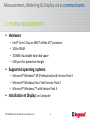
2. SYSTEM REQUIREMENTS
• Hardware
–
–
–
–
Intel® Core 2 Duo or AMD® Athlon X2® processor
2GB of RAM
320MB of available hard-disk space
USB port for protection dongle
• Supported operating systems:
– Microsoft® Windows® XP (Professional) with Service Pack 3
– Microsoft® Windows Vista® with Service Pack 2
– Microsoft® Windows 7® with Service Pack 3
• Installation et Display: on Computer
SOFTWARE 32 Cat.No 261 88: User Manual v1.3
5
Measurement, Metering & Display via e communicants
3. COMPATIBLE DEVICES*
• “Measure Software 32”
– Management up to 32 devices
• Version 1.07.00
– Range EMDX3
• Multifunction measuring devices:
– Modular - Cat.No 046 76
– Access - Cat.No 146 68
– Premium - Cat.No 146 69
* Measuring / metering devices
SOFTWARE 32 Cat.No 261 88: User Manual v1.3
6
Measurement, Metering & Display via e communicants
3. COMPATIBLE DEVICES*
– Range EMDX3
• Energy counters RS485 :
– Single-phase direct connection – Cat.Nos 046 77 (standard), 046 79 (MID)
– Three-phase direct connection – Cat.Nos 046 80 (standard), 046 83 (MID)
– Three-phase connection with CT– Cat.Nos 046 84 (standard), 046 86 (MID)
• Energy counters with pulse output (with the Concentrator Cat.No 046 87):
– Single-phase direct connection – Cat.Nos 046 70-81-72 (standard), 046 78 (MID)
– Three-phase direct connection – Cat.Nos 046 73 (standard), 046 82 (MID)
– Three-phase connection with CT– Cat.Nos 046 74 (standard), 046 85 (MID)
* Measuring / metering devices
SOFTWARE 32 Cat.No 261 88: User Manual v1.3
7
Measurement, Metering & Display via e communicants
3. COMPATIBLE DEVICES*
– Range DPX3
• DPX3 250 electronic only versions with integrated measurement unit
‐ via the communication module Cat.No 4 210 75
– Range DMX3 with protection unit – touchscreen (Cat.No 0 288 03/04)
– via the communication module Cat.No 0 288 05
* Measuring / metering devices
SOFTWARE 32 Cat.No 261 88: User Manual v1.3
8
Measurement, Metering & Display via e communicants
3. OTHERS COMPATIBLE DEVICES**
– Range DPX3
• DPX3 160 thermal-magnetic with integrated RCD
• DPX3 250 electronic, electronic with integrated RCD and thermal-magnetic
with integrated RCD
‐ via the communication module Cat.No 4 210 75
– Range DMX3 with protection unit – LCD screen (Cat.No 0 288 00/01/02)
– via the communication module Cat.No 0 288 05
** Devices without measuring / metering data
SOFTWARE 32 Cat.No 261 88: User Manual v1.3
9
Measurement, Metering & Display via e communicants
4. LANGUAGES AVAILABLE
• Languages:
–
–
–
–
–
–
–
Belgian Dutch
Belgian French
Dutch
English
French
Italian
Spanish
SOFTWARE 32 Cat.No 261 88: User Manual v1.3
10
Measurement, Metering & Display via e communicants
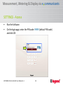
5. PRELIMINARY OPERATIONS
Before commissioning the installation we
recommend you to contact your technical
customer service to verify if a software
update is available.
(After receiving the update file follow the procedure detailed on pages 20 to 24 of this manual)
SOFTWARE 32 Cat.No 261 88: User Manual v1.3
11
Measurement, Metering & Display via e communicants
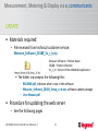
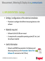
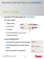
6. IMPLEMENTATION - installation
• Materials required
– Installation Kit (executable file .exe)
– A computer with a compatible operating system (XP, etc.)
SOFTWARE 32 Cat.No 261 88: User Manual v1.3
12
Measurement, Metering & Display via e communicants
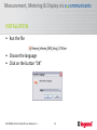
INSTALLATION
• Run the file
• Choose the language
• Click on the button “OK”
SOFTWARE 32 Cat.No 261 88: User Manual v1.3
13
Measurement, Metering & Display via e communicants
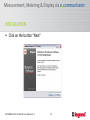
INSTALLATION
• Click on the button “Next”
SOFTWARE 32 Cat.No 261 88: User Manual v1.3
14
Measurement, Metering & Display via e communicants
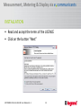
INSTALLATION
• Read and accept the terms of the LICENCE
• Click on the button “Next”
SOFTWARE 32 Cat.No 261 88: User Manual v1.3
15
Measurement, Metering & Display via e communicants
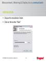
INSTALLATION
• Choose the installation Folder
• Click on the button “Next”
SOFTWARE 32 Cat.No 261 88: User Manual v1.3
16
Measurement, Metering & Display via e communicants
INSTALLATION
• Choose a Folder for the Start menu
(default: Legrand\Measure Software)
• Click in the button “Install”
SOFTWARE 32 Cat.No 261 88: User Manual v1.3
17
Measurement, Metering & Display via e communicants
INSTALLATION
• Installation completed
• Click on the button “Finish” (default: option “Run the
Measure software” selected)
SOFTWARE 32 Cat.No 261 88: User Manual v1.3
18
Measurement, Metering & Display via e communicants
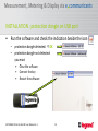
INSTALLATION : protection dongle on USB port
•
Run the software and check the indication beside the icon
– protection dongle detected: OK
– protection dongle not detected:
you must
•
•
•
Close the software
Connect the key
Restart the software
SOFTWARE 32 Cat.No 261 88: User Manual v1.3
19
Measurement, Metering & Display via e communicants
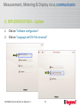
6. IMPLEMENTATION – Update
1.
2.
Click on “Software configuration”
Click on “Language and CSV files structure”
SOFTWARE 32 Cat.No 261 88: User Manual v1.3
20
Measurement, Metering & Display via e communicants
UPDATE
• Materials required:
– File received from technical customer service:
Measure_Software_26188_Vv_r_b.zip
Measure Software = Product Name
26188 = Product reference
Vv_r_b = Version of the embedded application
• The folder .zip contains the following files:
– README.pdf, indicates what’s new in the software
– Measure_Software_26188_Setup_v.r.b.exe, software update package
– User Manual.pdf
• Procedure for updating the web server
– See the following pages
SOFTWARE 32 Cat.No 261 88: User Manual v1.3
21
Measurement, Metering & Display via e communicants
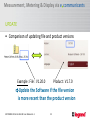
UPDATE
• Comparison of updating file and product versions
Example : File : V1.20.0
Product : V1.7.0
Update the Software if the file version
is more recent than the product version
SOFTWARE 32 Cat.No 261 88: User Manual v1.3
22
Measurement, Metering & Display via e communicants
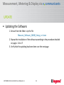
UPDATE
• Updating the Software:
1. Extract from the folder .zip the file
Measure_Software_26188_Setup_v.r.b.exe
2. Repeat the installation of the software according to the procedure detailed
on pages 11 to 17
3. Verify that the updating has been done: see the next page
SOFTWARE 32 Cat.No 261 88: User Manual v1.3
23
Measurement, Metering & Display via e communicants
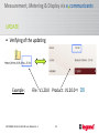
UPDATE
• Verifying of the updating
Example :
File : V1.20.0 Product : V1.20.0 OK
SOFTWARE 32 Cat.No 261 88: User Manual v1.3
24
Measurement, Metering & Display via e communicants
6. IMPLEMENTATION - Settings
• Settings / configurations of the electrical installation
– Procedure to configure the different measuring devices on the
software
• Materials required
– Software Cat.No 261 88 user manual
– A computer with a compatible operating system (XP, etc.) and
the software installed
• Useful Information
– Network and RS485 bus parameters for Gateways and
Measuring devices (use the Parameters Table of the
Software 32 contained on the CD Rom)
SOFTWARE 32 Cat.No 261 88: User Manual v1.3
25
Measurement, Metering & Display via e communicants
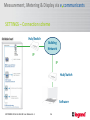
SETTINGS – Connection scheme
Hub/Switch
Building
Network
IP
IP
Hub/Switch
Software
SOFTWARE 32 Cat.No 261 88: User Manual v1.3
26
Measurement, Metering & Display via e communicants
SETTINGS – Computer
• Standard configuration of the computer, automatic IP address
Click OK to
confirm
SOFTWARE 32 Cat.No 261 88: User Manual v1.3
27
Measurement, Metering & Display via e communicants
SETTINGS - Access
•
•
Run the Software.
On the login page, enter the PIN code: 99999 (default PIN code)
and click OK
PIN
SOFTWARE 32 Cat.No 261 88: User Manual v1.3
28
Measurement, Metering & Display via e communicants
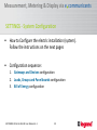
SETTINGS - System Configuration
•
How to Configure the electric installation (system).
Follow the instructions on the next pages
•
Configuration sequence:
1. Gateways and Devices configuration
2. Loads, Groups and Panel boards configuration
3. Bill of Energy configuration
SOFTWARE 32 Cat.No 261 88: User Manual v1.3
29
Measurement, Metering & Display via e communicants
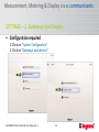
SETTINGS – 1. Gateways and Devices
• Configuration required
1. Click on “System Configuration”
2. Click on “Gateways and devices”
SOFTWARE 32 Cat.No 261 88: User Manual v1.3
30
Measurement, Metering & Display via e communicants
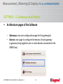
SETTINGS – 1. Gateways and Devices
•
Architecture pages of the Software
– Gateways: only one configuration page for the gateway(s).
– Devices: one page to configure the devices of each gateway
(a gateway bring together one or more devices connected to the
RS485 bus)
SOFTWARE 32 Cat.No 261 88: User Manual v1.3
31
Measurement, Metering & Display via e communicants
SETTINGS – 1. Gateways and Devices
•
Description of the Gateway page: structure and navigation
–
–
–
on the left: complete list of the gateways added (all the Gateways of the
installation). In red, the selected gateway.
on the right: parameters of the selected gateway
in the upper right: button to jump at the page of the Devices connected
to the selected gateway
SOFTWARE 32 Cat.No 261 88: User Manual v1.3
32
Measurement, Metering & Display via e communicants
SETTINGS – 1. Gateways and Devices
•
Description of the Devices page: structure and navigation
– on the left: complete list of the devices added (all the Devices connected
to the selected Gateway). In red, the selected device.
– on the right: parameters of the selected device.
– in the upper right: button to return to the Gateway page.
SOFTWARE 32 Cat.No 261 88: User Manual v1.3
33
Measurement, Metering & Display via e communicants
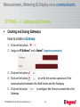
SETTINGS – 1. Gateways and Devices
•
Creating and Saving Gateways
How to create a Gateway
1. Click on the button
2. Assign an IP Address* and a Name* (required parameters)
3. Click on the button
4. Click on the button
to verify the correct operation of the
communication between the Web Server and the Gateway
5. Click on the button
to configure the Devices connected to the
Gateway
SOFTWARE 32 Cat.No 261 88: User Manual v1.3
34
Measurement, Metering & Display via e communicants
SETTINGS – 1. Gateways and Devices
•
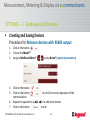
Creating and Saving Devices
Procedure for Measure devices with RS485 output
1.
2.
3.
Click on the button
Choose the Model**
Assign a Modbus Address*
4.
5.
Click on the button
Click on the button
to verify the correct operation of the
communication
Repeat the operations 1. 2. 3. to add more devices
Click on the button
to end
6.
7.
SOFTWARE 32 Cat.No 261 88: User Manual v1.3
and a Name* (required parameters)
35
Measurement, Metering & Display via e communicants
SETTINGS – 1. Gateways and Devices
•
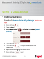
Creating and Saving Devices
Procedure for Measure devices with pulse output (details on next
page)
1.
2.
3.
Click on the button
Choose the Model**
Assign a Modbus Address*
parameters)
4.
5.
Click on the button
Click on the button
to verify the correct operation of the
communication
Repeat the operations 1. 2. 3. to add more devices
Click on the button
to end
6.
7.
SOFTWARE 32 Cat.No 261 88: User Manual v1.3
, the Position* and the Name* (required
36
Measurement, Metering & Display via e communicants
SETTINGS – 1. Gateways and Devices
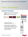
Details for Pulse output Meters:
–
Position: is the input of the Concentrator (Cat.No
046 87) on which the counter is connected
–
Verification by the button
Click on the button to check the proper
functioning of the communication, as well as
the input assignment of the Concentrator
shown in the "Position"
SOFTWARE 32 Cat.No 261 88: User Manual v1.3
37
Measurement, Metering & Display via e communicants
SETTINGS – 1. Gateways and Devices
•
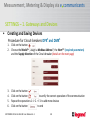
Creating and Saving Devices
Procedure for Circuit-breakers DPX3 and DMX3
1.
2.
Click on the button
Choose the Model**, assign a Modbus Address*, the Nom** (required parameters)
and the Supply direction of the Circuit-breaker (details on the next page)
3.
4.
5.
6.
Click on the button
Click on the button
to verify the correct operation of the communication
Repeat the operations 1. 2. 3. to add more devices
Click on the button
to end
SOFTWARE 32 Cat.No 261 88: User Manual v1.3
38
Measurement, Metering & Display via e communicants
SETTINGS – 1. Gateways and Devices
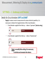
Details for Circuit-breakers DPX3 and DMX3:
-
Supply: to ensure correct measurement of various electrical quantities, it is
necessary to indicate the Supply direction of the circuit-breakers:
• Circuit-breaker supplied from the top → choose “upstream” (Default setting)
•
Circuit-breaker supplied from the top → choose “downstream”
Note: to modify this setting it is necessary
to delete and recreate the device.
SOFTWARE 32 Cat.No 261 88: User Manual v1.3
39
Measurement, Metering & Display via e communicants
SETTINGS – 1. Gateways and Devices
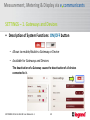
• Description of System Functions: ON/OFF button
– Allows to enable/disable a Gateway or Device
– Available for Gateways and Devices
The deactivation of a Gateway causes the deactivation of all devices
connected to it.
SOFTWARE 32 Cat.No 261 88: User Manual v1.3
40
Measurement, Metering & Display via e communicants
SETTINGS – 1. Gateways and Devices
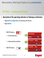
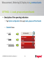
• Description of the operating indications of Gateways and Devices
– Page System configuration, for Gateways and Devices
– Page Devices
– ON/OFF button =
• Correct operation
• Communication problem
– ON/OFF button =
SOFTWARE 32 Cat.No 261 88: User Manual v1.3
41
Measurement, Metering & Display via e communicants
SETTINGS – 1. Gateways and Devices
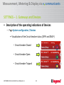
• Description of the operating indications of Devices
– Page System configuration / Devices
• Visualization of the Circuit-breaker status (DPX3 and DMX3)
– Circuit-breaker Closed
– Circuit-breaker Open
– Circuit-breaker Tripped
SOFTWARE 32 Cat.No 261 88: User Manual v1.3
42
Measurement, Metering & Display via e communicants
SETTINGS – 1. Gateways and Devices
• Description of System Functions: Display
– Page Consumption Grand Total / Partial / Details
– ON/OFF Button =
SOFTWARE 32 Cat.No 261 88: User Manual v1.3
Data non recorded
43
Measurement, Metering & Display via e communicants
SETTINGS – 1. Gateways and Devices
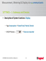
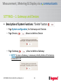
• Description of System Functions: “Delete” button
– Page System configuration, for Gateways and Devices
– Page Devices,
allows to delete a Device
– Page Gateway,
allow to delete a Gateway
• NOTE: To erase a Gateway, is necessary initially delete all the devices
connected to it!
SOFTWARE 32 Cat.No 261 88: User Manual v1.3
44
Measurement, Metering & Display via e communicants
SETTINGS – 1. Gateways and Devices
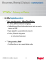
• List of the Required parameters:
– * Highly required parameters – Address/Name/Position:
• IP Address, a different IP address for each gateway
• Modbus Address, a different Modbus address for each device connected to
the same bus RS485
• Name, impossible to use several times the same name
• Positions, different for wiring reasons
– only for Counters with pulse output
– ** Useful parameter – Model:
• Possibility to have one, two or several identical models
SOFTWARE 32 Cat.No 261 88: User Manual v1.3
45
Measurement, Metering & Display via e communicants
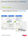
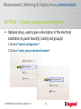
SETTINGS – 2. Loads, groups and panel boards
• Optional setup, used to give a description of the electrical
installation by panel board(s), load(s) and group(s)
1. Click on “System configuration”
2. Click on “Loads, groups and panels boards”
SOFTWARE 32 Cat.No 261 88: User Manual v1.3
46
Measurement, Metering & Display via e communicants
SETTINGS – 2. Loads, groups and panel boards
• Creating Panel boards
for a physical distribution of the different panel boards of the installation
Recommended architecture: only one Gateway per Panel board
Click on “Panel boards”
SOFTWARE 32 Cat.No 261 88: User Manual v1.3
47
Measurement, Metering & Display via e communicants
SETTINGS – 2. Loads, groups and panel boards
• Creating Loads
are available:
– 6 “pre-defined” categories (heating, air conditioning, etc.)
according by the Thermal Regulations 2012 (RT 2012)
– Category “Others” to display the measurement without Load assigned
– 8 additional categories,
user-creatable
Maximum of 14 loads
SOFTWARE 32 Cat.No 261 88: User Manual v1.3
48
Measurement, Metering & Display via e communicants
SETTINGS – 2. Loads, groups and panel boards
• Creating Groups
for a logical distribution of the measuring points of the installation
– Each device may be associated with several groups simultaneously
(maximum 5).
SOFTWARE 32 Cat.No 261 88: User Manual v1.3
49
Measurement, Metering & Display via e communicants
SETTINGS – 2. Loads, groups and panel boards
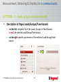
•
Description of Pages Loads/Groups/Panel boards
– on the left: complete list of the Loads, Groups or Panel boards.
In red, the selected Load/Group/Panel board
– on the right: specific parameters of the selected Load/Group/Panel
board
SOFTWARE 32 Cat.No 261 88: User Manual v1.3
50
Measurement, Metering & Display via e communicants
SETTINGS – 2. Loads, groups and panel boards
•
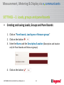
Creating and saving Loads, Groups and Panel boards
1. Click on “Panel boards, Load types or Measure groups”
2. Click on the button
3. Enter the Name and the Description/Location (Description and location
only for Panel boards and Measure groups)
4. Click on the button
SOFTWARE 32 Cat.No 261 88: User Manual v1.3
51
Measurement, Metering & Display via e communicants
SETTINGS – 2. Loads, groups and panel boards
•
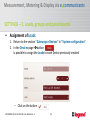
Assignment of Panel boards
1. Return to the section “Gateways e Devices” in “System configuration”
2. In the Gateways page, is possible to assign each gateway (previously
created) to a Panel board (a gateway can be assigned to only one panel
board)
– Click on the button
SOFTWARE 32 Cat.No 261 88: User Manual v1.3
52
Measurement, Metering & Display via e communicants
SETTINGS – 2. Loads, groups and panel boards
•
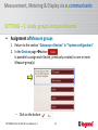
Assignment of Loads
1. Return to the section “Gateways e Devices” in “System configuration”
2. In the Devices page button
is possible to assign the Loads to each Device previously created
– Click on the button
SOFTWARE 32 Cat.No 261 88: User Manual v1.3
53
Measurement, Metering & Display via e communicants
SETTINGS – 2. Loads, groups and panel boards
•
Assignment of Measure groups
1. Return to the section “Gateways e Devices” in “System configuration”
2. In the Devices page button
Is possible to assign each Device, previously created, to one or more
Measure group(s)
– Click on the button
SOFTWARE 32 Cat.No 261 88: User Manual v1.3
54
Measurement, Metering & Display via e communicants
SETTINGS – 2. Loads, groups and panel boards
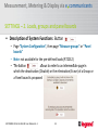
• Description of System Functions: Button
– Page “System Configuration”, then page “Measure groups” or “Panel
boards”
– Note: not available for the pre-defined loads (RT2012)
– The button
allows to enter to an intermediate page in
which the deactivation (Disable) or the elimination (Erase) of a Group or
a Panel board is proposed
SOFTWARE 32 Cat.No 261 88: User Manual v1.3
55
Measurement, Metering & Display via e communicants
SETTINGS – 2. Loads, groups and panel boards
• Description of the operating indications
– Page System configuration then page Loads, groups and Panel boards
– Disabled Status:
• Loads
• Groups
• Panel boards
SOFTWARE 32 Cat.No 261 88: User Manual v1.3
56
Measurement, Metering & Display via e communicants
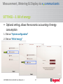
SETTINGS – 3. Bill of energy
• Optional setting, allows the economic accounting of energy
consumption
1. Click on “System configuration”
2. Click on “Bill of energy”
SOFTWARE 32 Cat.No 261 88: User Manual v1.3
57
Measurement, Metering & Display via e communicants
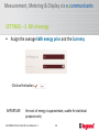
SETTINGS – 3. Bill of energy
•
Assign the average kWh energy price and the Currency
- Click on the button
IMPORTANT:
the cost of energy is approximate, usable for statistical
purposes only
SOFTWARE 32 Cat.No 261 88: User Manual v1.3
58
Measurement, Metering & Display via e communicants
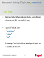
7. USE: Access
•
The access to the Software data is protected, a identification
code is required (PIN code and PUK code)
•
3 types of “default” users
– “administrator”
– “installer”
– “user”
The home page ("home") will be different depending on the type of user
It is possible to add other users
SOFTWARE 32 Cat.No 261 88: User Manual v1.3
59
Measurement, Metering & Display via e communicants
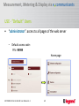
USE - “Default” Users
•
“administrator”: access to all pages of the web server
– Default access code:
PIN : 99999
Home page
SOFTWARE 32 Cat.No 261 88: User Manual v1.3
60
Measurement, Metering & Display via e communicants
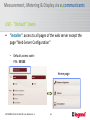
USE - “Default” Users
•
“installer”: access to all pages of the web server except the
page “Web Server Configuration”
– Default access code:
PIN : 55555
Home page
SOFTWARE 32 Cat.No 261 88: User Manual v1.3
61
Measurement, Metering & Display via e communicants
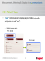
USE - “Default” Users
•
“user”: limited access to display pages of data (not possible
configuration in mode “user”)
– Default access code :
PIN : 11111
Home page
SOFTWARE 32 Cat.No 261 88: User Manual v1.3
62
Measurement, Metering & Display via e communicants
USE - Access
•
Change of the Access Parameters:
The access parameters are changeable only in ”administrator” mode
–
Possible actions:
•
•
•
•
–
Change of the Name and of the PIN code (5 characters)
Change of the accessible pages
Enabling/Disabling of a user
Deleting of a user
Procedure:
•
•
•
Choose from the menu the user to edit
Make the changes
Click on the button
Note: only the ”administrator” can change these parameters; the user
“administrator” should be changed by another “administrator”
SOFTWARE 32 Cat.No 261 88: User Manual v1.3
63
Measurement, Metering & Display via e communicants
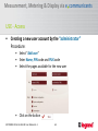
USE - Access
•
Creating a new user account by the “administrator”
Procedure:
• Select “Add user”
• Enter Name, PIN code and PUK code
• Select the pages available for the new user
• Click on the button
SOFTWARE 32 Cat.No 261 88: User Manual v1.3
64
Measurement, Metering & Display via e communicants
DISPLAY - Devices
•
Description of the display page of the “Devices”
(for the installers)
–
–
–
–
–
1. Gateway Name
2. Device Name
3. Load type
4. Circuit-breaker Status (if available on the Device)
5. Communication Status (ON: /OFF: / )
2
1
3
4
5
SOFTWARE 32 Cat.No 261 88: User Manual v1.3
65
Measurement, Metering & Display via e communicants
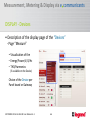
DISPLAY - Devices
• Description of the display page of the “Devices”
‐ Page “Measure”
• Visualization of the
– Energy/Power/V/A/Hz
– THD/Harmonics
(if available on the Device)
Choice of the Device per
Panel board or Gateway
SOFTWARE 32 Cat.No 261 88: User Manual v1.3
66
Measurement, Metering & Display via e communicants
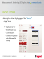
DISPLAY - Devices
•Description of the display page of the “Devices”
‐ Page “State”
• Visualization of the
– Circuit-breaker status
– Last three alarms
– Current or Temperature
value that caused the
last trip.
SOFTWARE 32 Cat.No 261 88: User Manual v1.3
67
Measurement, Metering & Display via e communicants
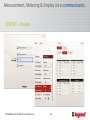
DISPLAY - Devices
SOFTWARE 32 Cat.No 261 88: User Manual v1.3
68
Measurement, Metering & Display via e communicants
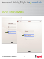
DISPLAY - Consumptions
•
Description of the display page of the “Consumptions”
(for energy managers)
–
–
–
–
1. Measure Group
2
2. Device Name
1
3. Load Type
4. Circuit-breaker Status (if available on the Device)
–
5. Communication Status
3
4
5
3 ways of displaying data
–
–
–
Grand Total (Consumption of the entire installation )
Partials (Consumptions per Load and/or Measure
group)
Details (Consumptions of a single Device)
SOFTWARE 32 Cat.No 261 88: User Manual v1.3
69
Measurement, Metering & Display via e communicants
DISPLAY - Consumptions
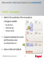
•
Details of the visualization of the consumptions
3 histograms available
– Day (per hour)
– Month (per day)
– Year (per month)
•
Comparison between the current
and the previous value
(ex. today/yesterday, etc.)
•
Values in kWh and € (default)
SOFTWARE 32 Cat.No 261 88: User Manual v1.3
70
Measurement, Metering & Display via e communicants
DISPLAY - Total Consumption
SOFTWARE 32 Cat.No 261 88: User Manual v1.3
71
Measurement, Metering & Display via e communicants
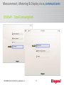
DISPLAY - Total Consumption
• Display page “Grand Total”
– Visualization of Global Consumptions
(Ea +) on histograms
• Per day/month/year
• Histogram per Load
SOFTWARE 32 Cat.No 261 88: User Manual v1.3
72
Measurement, Metering & Display via e communicants
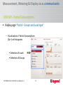
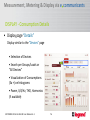
DISPLAY - Partial Consumption
SOFTWARE 32 Cat.No 261 88: User Manual v1.3
73
Measurement, Metering & Display via e communicants
DISPLAY - Partial Consumption
• Display page “Partial - Groups and Load type”
– Visualization of Partial Consumptions
(Ea +) on histograms
• Selection of Loads
• Selection of Groups
SOFTWARE 32 Cat.No 261 88: User Manual v1.3
74
Measurement, Metering & Display via e communicants
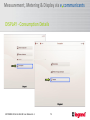
DISPLAY - Consumption Details
SOFTWARE 32 Cat.No 261 88: User Manual v1.3
75
Measurement, Metering & Display via e communicants
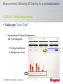
DISPLAY - Consumption Details
• Display page “Details”
Display similar to the “Devices” page
• Selection of Devices
• Search per Groups/Loads or
"All Devices“
• Visualization of Consumptions
(Ea +) on histograms
• Power, V/A/Hz, THD, Harmonics
(if available)
SOFTWARE 32 Cat.No 261 88: User Manual v1.3
76
Measurement, Metering & Display via e communicants
HISTORICAL of Consumptions - standard CSV
•
Exporting a report in standard.CSV format
– Compatible with Excel and “csv” files reader
– Configurable Fields separator in “Web Server Configuration” “CSV
and other settings”
Select:
•
•
CSV decimal separator: “comma” (default) or “point”
CSV fields separator: “semicolon” (default) o “comma”
SOFTWARE 32 Cat.No 261 88: User Manual v1.3
77
Measurement, Metering & Display via e communicants
HISTORICAL of Consumptions - Saving data on HD
•
Saving data on the hard disk of the computer
– Folder path for saving data configurable in “Software Configuration”
“Language and structure CSV files”
SOFTWARE 32 Cat.No 261 88: User Manual v1.3
78
Measurement, Metering & Display via e communicants
HISTORICAL of Consumptions - File Details
•
Automatic creation of files according to the System
Configuration
– “Energy” (Consumptions Ea+, per Device/Loads/Groups)
– “Devices” (several data per Device)
– “Settings”
SOFTWARE 32 Cat.No 261 88: User Manual v1.3
79
Measurement, Metering & Display via e communicants
HISTORICAL of Consumptions - Files “Energy”
•
“Energy”: name type_year-month_version
– .._type_..: distribution of Consumptions
•
•
•
groups_..: per Measure Groups
loads_..: per Loads
devices_..: per Devices
– .._year-month..: sampling period
– .._version..: in case of changes (adding of a Load/group/…)
SOFTWARE 32 Cat.No 261 88: User Manual v1.3
80
Measurement, Metering & Display via e communicants
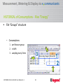
HISTORICAL of Consumptions - Files “Energy”
•
File “Groups” structure
– Consumptions:
1. per Measure group
2. in kWh
3. sampling every 15min
SOFTWARE 32 Cat.No 261 88: User Manual v1.3
3
81
1
2
Measurement, Metering & Display via e communicants
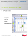
HISTORICAL of Consumptions - Files “Energy”
•
File “Loads” structure
– Consumptions:
1. per Load
2. in kWh
3. sampling every 15min
SOFTWARE 32 Cat.No 261 88: User Manual v1.3
3
1
2
82
Measurement, Metering & Display via e communicants
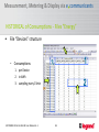
HISTORICAL of Consumptions - Files “Energy”
•
File “Devices” structure
– Consumptions:
1
3
1. per Device
2. in kWh
3. sampling every 15min
SOFTWARE 32 Cat.No 261 88: User Manual v1.3
2
83
Measurement, Metering & Display via e communicants
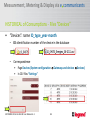
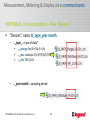
HISTORICAL of Consumptions - Files “Devices”
•
“Devices”: name ID_type_year-month
– ID: identification number of the device in the database
– Correspondence
•
•
Page Devices (System configuration Gateways and devices Devices)
In CSV files “Settings”
SOFTWARE 32 Cat.No 261 88: User Manual v1.3
84
Measurement, Metering & Display via e communicants
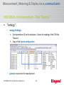
HISTORICAL of Consumptions - Files “Devices”
•
“Devices”: name ID_type_year-month
– .._type_..: type of data*
•
•
•
…_energy: Ea+/Er+/Ea-/Er-/Es
…_stat: statistics U/V/I/f/P/Q/S/THD
…_thd: THD I/U/V
– .._year-month..: sampling period
SOFTWARE 32 Cat.No 261 88: User Manual v1.3
85
Measurement, Metering & Display via e communicants
HISTORICAL of Consumptions - Files “Devices”
•
“Settings”:
– energy Settings:
•
•
–
Correspondence ID on the database - Device for reading of the CSV files
“Devices”
Copy of the System configuration
general: reserved to the manufacturer
SOFTWARE 32 Cat.No 261 88: User Manual v1.3
86
Measurement, Metering & Display via e communicants
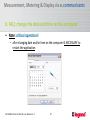
8. FAQ: change the date and time on the computer
• Note: critical operation!
– after changing date and/or time on the computer IS NECESSARY to
restart the application
SOFTWARE 32 Cat.No 261 88: User Manual v1.3
87
Measurement, Metering & Display via e communicants
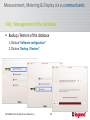
FAQ : Management of the database
• Backup / Restore of the database
1. Click on “Software configuration”
2. Click on “Backup / Restore”
SOFTWARE 32 Cat.No 261 88: User Manual v1.3
88
Measurement, Metering & Display via e communicants
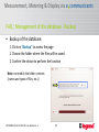
FAQ : Management of the database - Backup
• Backup of the database:
1. Click on “Backup” to access the page
2. Choose the folder where the files will be saved
2. Confirm the choice to perform the function
Note: not modify the folder contents
(names and types of files, etc..)!
SOFTWARE 32 Cat.No 261 88: User Manual v1.3
89
Measurement, Metering & Display via e communicants
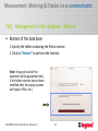
FAQ : Management of the database - Restore
• Restore of the data base:
1. Specify the folder containing the files to restore
2. Click on “Restore” to perform the function
Note: the good result of the
operation will be guaranteed only
if the folder contents has not been
modified after the backup (names
and types of files, etc..)
SOFTWARE 32 Cat.No 261 88: User Manual v1.3
90
Measurement, Metering & Display via e communicants
FAQ : Network type and access mode
•
LAN/intranet:
– Private network
– Addresses and rights managed by the Manager of the building
SOFTWARE 32 Cat.No 261 88: User Manual v1.3
91
Measurement, Metering & Display via e communicants
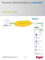
FAQ : LAN / Intranet
Hub/Switch
LAN/intranet
IP1
SOFTWARE 32 Cat.No 261 88: User Manual v1.3
92
IP2
Measurement, Metering & Display via e communicants
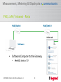
FAQ : LAN / Intranet - Ports
Hub/Switch
Hub/Switch
Software
•
Software/Computer to the Gateway
–
Port 502, Modbus TCP
SOFTWARE 32 Cat.No 261 88: User Manual v1.3
93