1
APOLLO
Counter/Classifier
Field Unit Instruction Manual
DIAMOND TRAFFIC PRODUCTS
PO BOX 1455
76433 ALDER STREET
OAKRIDGE, OR 97463
VERSION: 1.21
ISSUE DATE: 09/01/2006
Page 2
TABLE OF CONTENTS
I. INTRODUCTION
Page 5
I.A.
HOW TO USE THIS MANUAL
7
I.B.
COMMUNICATION WITH THE APOLLO
8
I.C.
SYSTEMS COMPONENTS
8
I.D.
FEATURES NOT AVAILABLE FROM THE KEYPAD
9
II. HARDWARE
Page 10
II.A.
KEYPAD
10
II.B.
LCD DISPLAY
11
II.C.
SERIAL PORT
11
II.D.
ROAD TUBES
12
III. QUICK SETOUT MODES
Page 14
III.A.
THE TWO BASIC OPERATION MODES
14
III.B.
RAW PER VEHICLE STORAGE AND SPECIFIC FUNCTIONS
15
III.C.
COUNT STORAGE AND SPECIFIC FUNCTIONS
17
IV. ADVANCED SELECTION MODE
Page 18
IV.A.
NOT COLLECTING DATA MENU
18
IV.B.
COLLECTING DATA MENU
19
IV.C.
START COLLECTING
19
IV.c.1
21
Questions Asked With Any Storage Mode
Copyright © 2006 High Leah Electronics, Inc.
ALL RIGHTS RESERVED
TABLE OF CONTENTS
Page 3
IV. ADVANCED SELECTION MODE Continued
IV.D.
SHOW STATUS
22
IV.E.
DELETE FILES
23
IV.F.
VIEW LANE TOTALS
24
IV.G.
CONFIGURE SYSTEM
25
IV.H.
COLD RESTART
26
IV.I.
MONITOR LANES
28
IV.J.
MONITORING RAW OR BINNED DATA COLLECTION
28
IV.K.
MONITORING COUNT DATA COLLECTION
29
APPENDIX A. TROUBLE SHOOTING
Page 30
APPENDIX B. MEMORY USAGE
Page 31
B.1.
RAW DATA COLLECTION
31
B.2.
COUNT DATA COLLECTION
32
APPENDIX C. PLUGS & CONNECTORS
Page 32
APPENDIX D. DEFAULT BIN TABLES
Page 33
Copyright © 2006 High Leah Electronics, Inc.
ALL RIGHTS RESERVED
TABLE OF CONTENTS
Page 4
APPENDIX E. ROAD TUBE PROBLEMS & SOLUTIONS
Page 35
E.1.
MISSED AXLES
35
E.2.
EXTRA AXLES
38
E.3.
BAD SPEED AND/OR LENGTH
38
E.4.
SNMIS (SENSOR MISS) FOR ENTIRE VEHICLE
39
E.5.
ONE VEHICLE SHOWN AS TWO
39
E.6.
TWO VEHICLES SHOWN AS ONE
40
E.7.
ROAD TUBE SETUP THAT DOES NOT CAUSE ERRORS
40
APPENDIX F GPS SETUP
Copyright © 2006 High Leah Electronics, Inc.
ALL RIGHTS RESERVED
Page 41
TABLE OF CONTENTS
Page 5
I. INTRODUCTION
Thank you for purchasing the Apollo Field Unit. You have purchased one of the finest traffic
classification counters available. This manual describes the operation and programming of the
Apollo Field Unit. Please read this manual before attempting full operation. The Apollo Quick
Start guide is available as an appendium to this manual.
What is an "Apollo Field Unit"?
The Apollo is a traffic data-gathering instrument for use in the field. Speed, Length, and Number
of Axles are a few types of data that can be gathered with this instrument.
The cast aluminum case is durable, light, and weather resistant. The interior keypad & display
are both sealed to prevent moisture from damaging them. In addition, a rubber seal is installed
around the lid to further protect the unit from the weather.
The case also contains a lid securing mechanism and aluminum carrying handle. The outside
rear of the case contains two or four Air switches. The Battery Charger and the Serial Interface
plug are on the face panel of the counter.
The electronic circuit board inside the case contains the microprocessor, backup battery, battery
charger network, memory, and all other support circuitry for the unit.
Some Tips to Prolong the Life of Your Apollo
When collecting data avoid placing unit in drainage ditches or areas prone to flooding.
Always dry the unit out completely after removing from the field.
Always push on the dust caps onto unused plugs.
Keeping the battery fully charged will prolong its service life. Recharge the battery every
six weeks when not in use.
Disconnect the serial interface plug if serial communication is not required. This will
substantially reduce power consumption and prolong battery life.
Do not attempt service without qualified personnel. The components of the
Apollo are very static sensitive, and improper handling can damage boards. All
hardware is covered in the Apollo Hardware Manual.
Copyright © 2006 High Leah Electronics, Inc.
ALL RIGHTS RESERVED
INTRODUCTION
Page 6
FCC Compliance
FCC Compliance
Note: This equipment has been tested and found to comply with the limits for a Class B digital
device, pursuant to part 15 of the FCC Rules. These limits are designed to provide reasonable
protection against harmful interference in a residential installation. This equipment generates,
uses and can radiate radio frequency energy and, if not installed and used in accordance with
the instructions, may cause harmful interference to radio communications. However, there is no
guarantee that interference will not occur in a particular installation. If this equipment does
cause harmful interference to radio or television reception, which can be determined buy turning
the equipment off and on, the user is encouraged to try to correct the interference by one or
more of the following measures:
Reorient or relocate the receiving antenna.
Increase the separation between the equipment and receiver.
Connect the equipment into an outlet on a circuit different from that to which the
receiver is connected.
Consult the dealer or an experienced radio/TV technician for help.
The user is cautioned that changes or modifications not expressly approved by Diamond Traffic
Products could void the user’s authority to operate the equipment.
Copyright © 2006 High Leah Electronics, Inc.
ALL RIGHTS RESERVED
INTRODUCTION
Page 7
I.A. HOW TO USE THIS MANUAL
This manual completely describes the use of the Apollo. The only thing not covered in this
manual is programming & retrieving data from the serial port with a PC Computer. This is
covered in the Centurion Windows Software.
Do I Have To Read The Whole Manual?
For Quick operation please refer to the Apollo Quick Start Guide. Anybody using an Apollo
should read all of Section I, II, and III of this manual. This will familiarize you with the basic
equipment provided, what types of data you can collect. From that point there are three methods
of operation:
Method 1 -
To operate the Apollo entirely from its built in keypad.
All setup and configuration can be done from the keypad and is recommended as
the easy 4 Step Wizard is the quickest setup Method. Data maybe collected by a
DATA HOG, a laptop computer or PDA running CENTURION WINDOWS software. If this is the method you want to use, first read section IV.a and IV.b. Also
Refer to the Apollo Quick Start Guide when using simple 4 Step Wizard.
Method 2 -
To operate the Apollo only from a computer (using Centurion Windows
Software).
Setup and configuration can be done from a computer (in addition to retrieving
the collected data). If this is the method you want to use, simply refer to the
Software help screens for more information. Use this field unit manual for
clarification and technical information on the Apollo.
Method 3 -
To operate the Apollo using both a computer and its built in key
board.
This is the most common method since you might not always have a computer
with you, and becoming familiar with the keypad operation is always useful. We
suggest run the counter using the built in keypad (first read section IV.a and IV.b)
After collecting some data with the Apollo, move on to using the software to
collect your data.
Copyright © 2006
2001 High Leah Electronics, Inc.
ALL RIGHTS RESERVED
Inc.
ALL RIGHTS RESERVED
INTRODUCTION
Page 8
I.B. COMMUNICATION WITH THE APOLLO
Communicating with the Apollo is done through the built in Keypad/Display, or through the serial
port to an IBM PC compatible computer or laptop. Our Centurion software package allows such
advanced features as:
"Wizard style" windows and "User-Friendly" menus.
Complete Database functions with viewing and editing of all collected data.
XMODEM transfers for data file retrieval, with later file format conversion utilities &
detailed printouts with analysis (hourly and daily summaries).
Complete monitoring and configuration.
To learn more about using these programs, refer to the Software Instruction Manual. Note that
the Apollo serial access is not restricted to use with any particular type of computer. Any
computer that supports a standard serial communications (RS232) will suffice. In the case of
newer PC computers that do not have a serial port, USB to serial adapters are widely available
from computer retailers and provide a serial port to these newer laptops and PC’s.
I.C. SYSTEM COMPONENTS
You must have the following equipment to use the Apollo.
purchased from Diamond Traffic Products.
All of this equipment can be
Apollo Field Unit Instruction Manual / Apollo Quick Start Guide.
Centurion Windows Software
A Battery Charger or counter fitted with a solar panel on the lid.
A Serial Interface Cable between the counter and a computer (DB9 pin).
Road tube sensors and assorted hardware for securing to road. (i.e. nails, road tube
grips, hammer and tape measure.)
Computer. Ideally, this would be one of the many IBM-PC type computers available to
use the Centurion software.
Copyright © 2006
2001 High Leah Electronics, Inc.
Inc. RIGHTS RESERVED
ALL
ALL RIGHTS RESERVED
INTRODUCTION
Page 9
I.D. FEATURES NOT AVAILABLE FROM THE KEYPAD
The Apollo has some features which are not available directly from the counter keypad. Some
features require too much internal firmware to use from the keypad and therefore are only
accessible through the serial port, also some of these features only relate to serial port use, and
therefore are not needed from the keypad.
The following features are available from the serial port using the software package.
Data Retrieval - The most important serial counter function, the retrieval of collected
data.
Daylight Savings Time Adjust - You can manually or automatically have software set
the Apollo to handle daylight savings time changes. The Apollo will change the time and
adjust data appropriately, if you choose automatic.
Counter Serial Number - The counter contains a built in firmware serial number, This
serial number, usually set by us at the factory, is included with all data files so that the
specific counter that collected the data can be easily identified. You can optionally set
your own serial number using the Alt+F10 function from the main counter link screen in
the software.
GPS Coordinates - The Apollo is equipped to read GPS coordinates from any NMEA
compatible receiver with a serial output. Connecting to the GPS receiver will allow the
unit to download the coordinated straight into the Apollo information lines for later site
identification. Refer to Appendix F.1
Copyright © 2006
2001 High Leah Electronics, Inc.
Inc. RIGHTS RESERVED
ALL
ALL RIGHTS RESERVED
INTRODUCTION
II. HARDWARE
This section describes the hardware components associated with the Apollo counter.
II.A. KEYPAD
The Apollo contains a built in 16-key keypad. With this keypad and the built in four (4) line twenty
(20) characters per line LCD display (section III.b.) you can completely program and operate the
Apollo. When the ALT key is held down while you are pressing another key, an alternate set of
keys is available to the user. The table below shows the alternate keys.
Table 1 – Alternate Keypad Entry
0
ALT
1
ABC DEF
2
3
GHI
JKL
4
5
MNO PQR
6
7
8
9
Clear
STU
VWX
YZ[
-./
Abort
A…
Note that if the ALT key is continuously held and the number key is pressed, again, the letter will
scroll through the following possibilities of letters:
ABCDEFGHIJKLMNOPQRSRUVWXYZ[]^abcdefghijklmnopqrstuvwxyz{|}!"#$%&'()
*+,-./0123456789:;?@
For example, if you wanted the letter "W" you would press "ALT" and "7" simultaneously. Note
that "V" appears in the space, as Table 1 shows. While still holding the "ALT" key, press the "7"
key again, and the letter "W" will appear. Release the "ALT" key and the letter remains. You
can also press the right and left arrow keys (while the ALT key is down) to scroll through the
alphabet.
The rest of the keys are explained below:
ENTER
Used as a means of indicating to the Apollo that an option is complete,
and ready to be acted upon.
CLEAR
Used as means of backing up one question in a menu.
SPACE
The <<Space>> key inserts a space at the cursor location and will also allow
scrolling through options in ascending order.
Copyright © 2006 High Leah Electronics, Inc.
ALL RIGHTS RESERVED
HARDWARE
Page 11
This key allows viewing/selection of options in a descending order. Also used as
a non-destructive backspace key when entering a line of data.
This key allows viewing selection of options in ascending order. Also used to
move non-destructively one position to the right when entering a line of data.
ALT
Used only in conjunction with other keys; ALT allows existing keys to perform
alternate functions. Use of the ALT key is similar to the SHIFT key on a
typewriter keyboard, in that the ALT key must be pressed and held for the
duration of the associated keypress.
II.B. LCD DISPLAY
The Apollo is equipped with a four-line LCD display (Liquid Crystal Display). Each line displays
up to 20 letters or numbers. This display is used in conjunction with the keypad to program and
operate the Apollo. You will see various questions and information displayed at different times.
Please refer to the appropriate section of this manual for more information on specific questions
and displays.
The LCD type of display used in the Apollo consumes very little power, thereby minimizing
battery drain during setup and monitoring procedures. To further save battery power, the Apollo
will turn off power to the display when data collection is active and the display is not being used.
Road dust will inevitably cover the display from time to time, and the display will need to be
brushed off. When cleaning the display, it is best to attempt blowing off as much dust as
possible before wiping the surface with a soft damp cloth. This method limits the chances of
scratches being caused by the abrasive found in the dust.
II.C. SERIAL PORT
The serial port is used for the retrieval of traffic data that has been collected by the Apollo. All
serial devices are connected to the Apollo through the DB-9 Serial Port plug (located on the
lower right side of the face panel). Note that the Apollo can be completely programmed and
operated from the serial port. ( a PC USB to Serial adapter may be needed for newer PC’s)
The serial port supports 19200 : 8N1 Communication.
The retrieval of data must be done through the serial port, and the method of transfer is 1K
XMODEM with CRC error checking. An automatic switch to 128 Byte XMODEM transfer occurs
when the system gets 10 or more errors, indicating a noisy line. Data will transfer faster with
smaller blocks.
Copyright © 2006
2001 High Leah Electronics, Inc.
ALL RIGHTS RESERVED
HARDWARE
Page 12
Computer -
You will need to connect a computeror PDA to the Apollo to retrieve your data.
II.D. ROAD TUBES
Road Tubes (or just "Tubes") refer to hollow rubber tubes usually ranging from 30 to 100 feet in
length. These Tubes are stretched across the roadway so that oncoming vehicle traffic drives
over them. This generates a sound-wave (or an "air impulse"), which travels down the tube and
allows the electronics of the Apollo to determine that a vehicle axle has passed.
Note: there
will be loss of counts if road tubes longer then 60’ (20 meters) are used.
Tubes offer the advantage of being easily movable, quick to install, inexpensive, and capable of
detecting individual axles of a vehicle. Their disadvantages include rapid wear, hard to secure for
long periods, and drivers noticing the tubes and possibly changing speed, lanes, etc.
Follow these guidelines when using Tubes with the Apollo:
The counter will work with road tubes between 30' and 100' long. (note: tubes shorter
than 30’ will work but will damage the air switch over time)
If collecting Raw or Per Vehicle data, make sure each lane's tubes (two per lane) are the
SAME LENGTH. Also, try to stretch the tubes the same amount when securing them to
the roadway.
Make sure the Tubes are placed as squarely as possible to the oncoming traffic (so that
both wheels of a vehicle strike the tube simultaneously).
After each use, check the tubes for punctures or other damage.
Plug the end of the tube with a suitable device to keep dirt and water out.
How to connect the Tubes to a Apollo when collecting Raw Per Vehicle:
Get two equal length road tubes for each lane desired.
Install one road tube perpendicular to the direction of traffic across a Single lane of traffic.
You can string road tubes across multiple lanes using the "Lane Overlap" function or the
"Directional" mode. This is fully covered under Section III.c.).
Install the second road tube perpendicular to the direction of traffic from four feet or
122cm from the first tube.
Copyright © 2006 High Leah Electronics, Inc.
ALL RIGHTS RESERVED
HARDWARE
Page 13
Connect the road tube, which will be hit first by oncoming traffic into the 1st Input Nozzle
for the particular lane you are using.
Connect the road tube, which will be hit second by oncoming traffic to the 2nd Input
Nozzle for the particular lane you are using.
How to connect Tubes to a Apollo when collecting Count Data:
Install a road tube perpendicular to oncoming traffic across a single or dual lane of traffic.
Connect the road tube to the Nozzle on the Apollo for the lane you are using.
If you are using at least two lanes and you want to use Lane Subtraction or Directional
function, you may want to read about these functions in Section II.e for more information
on how to correctly install and connect tubes.
FOR IMPORTANT INFORMATION REGARDING TUBES AND POTENTIAL ERRORS,
SEE APPENDIX - E.
Copyright © 2006 High Leah Electronics, Inc.
ALL RIGHTS RESERVED
HARDWARE
Page 14
III. QUICK SET OUT MODES
This section of the manual discusses the three methods the Apollo can collect data.
III.A. THE TWO BASIC OPERATION MODES
The two modes are: 1) The Quick Set Out Mode and; 2) Advanced Selection (Operation Mode).
You should first become familiar with the three fundamental modes of operation. The mode that
you select determines the type of data that will be collected, and whether the information will be
combined with other entries or stored individually.
Raw (per vehicle)
This mode will store each vehicle in memory as it passes by. The
following information about each vehicle can be stored in memory: time,
speed, number of axles, spacing between each axle, overall length, and
bin classifications.
Count
The count mode is the simplest mode of operation. It is used when just a
vehicle count is desired. When using road Tubes or other Axle Sensors,
the Apollo provides the total number of axles detected, optionally
divided by two. Users specify a time interval, such as 15 minutes or every
hour, in which these total counts will be stored in memory.
The Apollo supports (2) two or (4) four Road Tube Airswitches. Road Tube Sensors are
considered "axle" sensors, since individual vehicle axles activate them.
This Apollo also contains many advanced sensor analysis routines to improve data accuracy,
including examining both sets of axle sensors and the tossing out of too short spacings (for
example: eliminating a road tube bounce, which can cause a false count), and the determination
of missed axles.
The Apollo has an added feature that lets the counter search for cars that tailgate other cars or
trucks. This will prevent two or three closely spaced cars from appearing as a class 8 truck or a
class 13 unidentified vehicle.
Copyright © 2006 High Leah Electronics, Inc.
ALL RIGHTS RESERVED
QUICK SET OUT MODES
Page 15
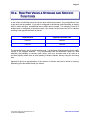
III.B. RAW PER VEHICLE STORAGE AND SPECIFIC
FUNCTIONS
In this mode, an individual record is kept for each vehicle encountered. Any combination of one
to two lanes can be enabled. If any lane is configured for directional mode (the ability to classify
traffic in either direction), an additional lane of traffic data is created. For example, if lane #1 is
enabled and is configured in directional mode, the counter would create lane #3 for vehicles
traveling in the opposite direction on lane #1.
Physical Lane
Opposite Direction Lane
Lane #1
Lane #3
Lane #2
Lane #4
The directional lane is not an actual separate lane - it is the same physical lane but simply traffic
moving in the opposite direction. It is recommended that the directional option be used
whenever the possibility of two-way traffic exists, such as a one-lane road or an area on a
two-lane highway where there is much passing of slower vehicles, thereby using the oncoming
lane.
Appendix B gives an approximation of the number of vehicles that can be stored in memory
depending upon which data format you choose.
Copyright © 2006
2001 High Leah Electronics, Inc.
Inc. RIGHTS RESERVED
ALL
ALL RIGHTS RESERVED
MODES, SENSORS, AND
QUICK
HOW
SETTO
OUT
USE
MODES
THEM
Page 16
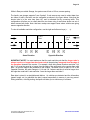
While in Raw per vehicle Storage, the system uses 4 feet or 122 cm, sensor spacing.
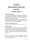
The Apollo, raw storage supports "Lane Overlap". If axle sensors are used to collect data from
two lanes of traffic, the lanes can be configured as shown in the figure below. Note that the
shorter tube is in the near lane (lane #1), and is activated first by oncoming traffic. This
configuration will allow you to collect data from two lanes using 4 road tubes where one set of
tubes crosses both lanes. Note: that lane overlap can support lanes where vehicles are going
same or opposite direction.
To view all available road tube configuration, use the right and left arrow keys (
1 to 2
Feet
1
3
2
Same Direction
4
).
1 to 2
Feet
1
4
2
3
Opposite Direction
IMPORTANT NOTE: You must make sure that for each road tube pair that the longer tube is
always equal to or longer than the shorter tube in the pair when measured from the edge of
the pavement closest to the counter. For example, when doing Same Direction road tube 3 (of
pair 1 & 3) must be equal to or longer from the edge of the pavement to the counter than road
tube 1 is from the edge of the pavement to the counter. The same is true for pairs 2 & 4. In the
Opposite Direction, the pairs change to 1 & 4 and 2 & 3 where road tube 4 must be longer from
the edge than road tube 1 and road tube 3 must be longer than road tube 2.
Raw data is stored in a straightforward fashion. As vehicles are detected and the information
(speed, length, etc.) is gathered, the data is stored sequentially in memory in one long record.
During collection, or during testing, the Apollo will allow you to monitor any or all lanes.
Copyright © 2006
2001 High Leah Electronics, Inc.
Inc. RIGHTS RESERVED
ALL
ALL RIGHTS RESERVED
MODES, SENSORS, AND
QUICK
HOW
SETTO
OUT
USE
MODES
THEM
Page 17
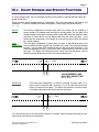
III.C. COUNT STORAGE AND SPECIFIC FUNCTIONS
In count storage mode, the only information stored is the number of vehicles that have been detected in each lane.
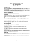
There are three sensor configurations for Count data. They are Lane Normal, Subtraction, and
Directional. To view all available road tube configuration, use the right and left arrow keys
(
).
Normal
Lane
Subtraction
This sensor configuration would be used when the counter can be located in a
center median of a roadway and road tube is counting traffic. On one side of the
median another road tube is counting traffic on the other side.The data from each
road tube is stored and in no way affects data from the other road tube. If the
Apollo has four airswitches, it is possible to count all four lanes if they are divided
by a center medium
This road tube configuration is used when you want to get individual lane count
from two different lanes of traffic from one side of the road. The road tube attached
to Lane 1 (or any other ODD numbered lane) is laid out across both lanes. The
road tube attached to Lane 2 (or the next even numbered lane) is laid out across
one lane. The Apollo will subtract the even lanes from the odd lane's count to
obtain the proper directional count for the odd numbered lane.
1 Foot
1
Directional
2
ODD NUMBERED LANE
MUST BE LONGER TUBE
(i.e. 1 or 3)
This road tube configuration is used for counting two-way traffic on a
narrow road. A road tube pair (such as 1-2 or 3-4) is laid out across both
lanes of a road one foot apart. The Apollo will determine (from the order
of actuation) the proper directional count for each lane.
1 Foot
1
2
You can monitor any or all lanes during collection or testing, with the system showing you the
current lane totals for the record interval.
Copyright © 2006
2001 High Leah Electronics, Inc.
Inc. RIGHTS RESERVED
ALL
ALL RIGHTS RESERVED
MODES, SENSORS, AND
QUICK
HOW
SETTO
OUT
USE
MODES
THEM
Page 18
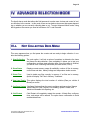
IV. ADVANCED SELECTION MODE
The Apollo has a mode that allows the field personnel to make more choices and control of various functions in the counter. In this mode, there are two basic main menus that appear depending on whether you are currently collecting data or not. To enter Advanced Menu mode, Using
the Keypad on the counter you need to hold down <ALT> and Press .
IV.A.
NOT COLLECTING DATA MENU
This menu appears when you first power the counter and are ready to begin collection. It contains the following options:
1 Start Collecting
The main option. It will ask a series of questions to determine the lanes
and format for data collection. Once completed, it allows you to test your
configuration, and then start collecting data. Once this option is finished,
you will be in the Collecting Data menu (see next section, IV.b.2).
2 Show Status
Displays current memory usage & availability, number of files in memory,
current time and date, battery voltage and temperature inside counter.
3 Delete Files
Used to delete any files currently in memory. If no files are in memory,
Apollo will display "No Files In Memory" if selected.
4 View Lane Totals This option displays the total number of vehicles (Raw per vehicle &
Binned) or counts.
5 Configure System Configure System allows the user to configure options such as Storage
Mode, Date and Time Formats, File Handling, Speed Formats, and
Maximum Allowable Axle Spacing, etc.
6 Cold Restart
Cold Restart will completely restart the counter. All data files, configurations, and setups will be erased. The option has a confirmation to avoid
accidental data loss.
Copyright © 2006 High Leah Electronics, Inc.
ALL RIGHTS RESERVED
ADVANCED SELECTION MODE
Page 19
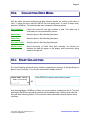
IV.B.
COLLECTING DATA MENU
After the Apollo has been configured and data collection started, the collecting data menu is
used. To reach the menu, press the ENTER key from sleep mode. To return to sleep mode,
press the CLEAR key. The collecting data menu contains the following options:
Stop Collecting
Closes the current file and stop collection of data. This option has a
confirmation to avoid accidental file closure.
Show Status
Same as option in Not Collecting Data menu.
Delete Files
Same as option in Not Collecting Data menu.
View Lane Totals
Same as option in Not Collecting data menu.
Monitor Lanes
Allows monitoring of Traffic Data while collecting. As vehicles are
detected, the data will appear on the display, while concurrently being
stored in the open file.
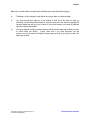
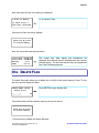
IV.C. START COLLECTING
The Start Collecting option asks many questions, depending on what type of Storage Mode you
plan on using. Press the "1" key from the menu and the display will show:
SELECT MENU OPTION:
Start Collecting
(_ _ _ _)
Press ENTER to begin the start collecting option.
nF
Note that pressing the CLEAR key will back you up one question. Holding down the ALT key and
pressing the ENTER key will skip all questions and immediately begin Testing Lanes under the
last used Start Collecting Options. This is useful to collect data under previously entered setup
conditions.
Copyright © 2006
2001 High Leah Electronics, Inc.
ALL RIGHTS RESERVED
Inc.
ALL RIGHTS RESERVED
ADVANCED
KEYPAD
SELECTION
OPERATION
MODE
Page 20
Before you use the Apollo to actually start collecting data, verify the following things:
The battery is fully charged (or will last as long as you plan on collecting data)
You have enough free memory in the counter to hold all of the data you plan on
collecting. Use the Show Status option to verify the amount of free memory. Appendix B
contains tables that will give you an idea of how much memory you need for different
collection options and modes.
You have used the configure system option to tell the counter what type of data you want
to collect (Raw per vehicle, Count). Note that if you have previously set the
counter, you will not need to Configure System again as long as you plan to collect the
same type of data.
Copyright © 2006
2001 High Leah Electronics, Inc.
ALL RIGHTS RESERVED
Inc.
ALL RIGHTS RESERVED
ADVANCED
KEYPAD
SELECTION
OPERATION
MODE
Page 21
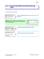
IV.c.1. Questions Asked With Count (Volume) Storage
Mode
The following questions are asked:
SETUP
Enter
Press
_ _
STEP #1 OF 3:
a Site ID and
<Enter> key:
_ _ _ _ _ _
Enter the appropriate information for this site, up to 15
characters.
NOTE: at any time you may enter in GPS coordinates or
Download them from a GPS device by holding down the
<ALT> and press the .
LAT=
◦
.
m
LON=
˚
.
m
*********************
Site:________________
SETUP STEP #2 OF 3:
Check Clock! <Enter>
If Ok, <0> To Change:
HH:MM:SS
MM/DD/YR
Enter the correct time and date here as needed.
SETUP STEP #3 OF 3:
Enter the correct time and date here as needed.
Waiting For Any
Vehicle...
Copyright © 2006
2001 High Leah Electronics, Inc.
ALL RIGHTS RESERVED
Inc.
ALL RIGHTS RESERVED
ADVANCED
KEYPAD
SELECTION
OPERATION
MODE
Page 22
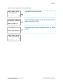
IV.D. SHOW STATUS
The Show Status option in the Advanced Menu allows display of the Unicorn Limited System
Status. This should always be performed prior to Starting Collection to ensure that there is
enough memory free to collect files. From the menu, press "2" and the display will show:
SELECT MENU OPTION:
Show Status
(_ _ _ _)
Press ENTER to show system status.
nF
First, the counter displays the amount of memory in the system:
Total Mem : 461000
Amount Used:
0
———————
461000
Copyright © 2006 High Leah Electronics, Inc.
ALL RIGHTS RESERVED
Displays the total amount of memory in your counter and how
much is left for use.
ADVANCED SELECTION MODE
Page 23
Next, how many files are in the memory is displayed:
n Files In Memory.
"n" is number of files.
Of these files, n
have been retrieved.
If there are no files, the screen displays:
There are No Files
In Counter Memory.
Next, the current time and date are shown:
Clock Time: HH:MM:SS
Clock Date: DD/MM/YY
Battery
: x.x.v
Temp.
: xx.x F
The current time, date, battery and temperature are
displayed. Note that the date will be displayed in the currently
selected format. The time and date can only be programmed
from Start Collecting sequence.
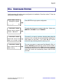
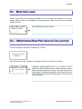
IV.E. DELETE FILES
The delete files option allows you to delete any or all files in the current memory. Press "3" from
the menu and the display will show:
SELECT MENU OPTION:
Delete Files
(_ _ _ _)
Press ENTER to begin deleting files.
nF
If there have been no files created in memory, the counter shows:
There Are No Files
In Counter Memory.
If files have been created, the display will show:
Copyright © 2006 High Leah Electronics, Inc.
ALL RIGHTS RESERVED
ADVANCED SELECTION MODE
Page 24
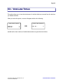
IV.F. VIEW LANE TOTALS
This option allows you to view the total amount of vehicles that have occurred from the last time
you Started collection.
When you select this option, a screen will appear similar to the following:
< View Lane Totals >
Lane #a :
Lane #b :
x
y
< View Lane Totals >
OR
Lane #a :
x
a and b are the lane numbers of enabled lanes and x and y are the total vehicles.
Copyright © 2006 High Leah Electronics, Inc.
ALL RIGHTS RESERVED
ADVANCED SELECTION MODE
Page 25
IV.G. CONFIGURE SYSTEM
Configure system will set the system configuration for installation. Press the number "5" from the
menu and the display will show:
SELECT MENU OPTION:
Configure System
(_ _ _ _)
Press ENTER to begin system configuration.
nF
< CONFIGURE SYSTEM >
This asks which format you require for the date. Options are:
MM/DD/YY, DD-MM-YY, and YY-MM-DD.
Select Date Display
Format: MM/DD/YY
< CONFIGURE SYSTEM >
Erase The First File
When Out Of Mem? Yes
< CONFIGURE SYSTEM >
Auto Create New File
When? Daily
Copyright © 2006
2001 High Leah Electronics, Inc.
ALL RIGHTS RESERVED
Inc.
ALL RIGHTS RESERVED
This asks if you want to continue collecting data when the
memory is full, or should the counter delete the oldest file to
make space for new data. If you select No the Unicorn
Limited will stop collecting when the memory is full.
The user may select to create new files Manually, Daily, or
Weekly. Manually means that the counter will only create a
file when you specifically tell it to.Daily means the counter will
automatically create a new file each day at midnight.Weekly
means the counter will automatically create a new file once
per week.
ADVANCED
KEYPAD
SELECTION
OPERATION
MODE
Page 26
< CONFIGURE SYSTEM >
SnMis Memory Storage
Mode: View Only
< CONFIGURE SYSTEM >
m
Select Maximum Axle
Spacing: 40.0’
This option is used to select what the counter should do with
sensor miss information. Sensor misses occur when a
vehicle does not cross both sensors (see lid instructions on
Unicorn Limited field unit for a description of each sensor
miss code). View Only will display sensor misses on the
screen when monitoring, but not store these misses to
memory. View & Store displays the misses and stores them
for later retrieval into memory. Note that storing sensor
misses in memory does use up memory that could be used
for data. Disabled causes the counter to ignore sensor
This option determines the longest spacing between any two
axles to be allowed when collecting Raw or Binned data
using two axle sensors. The counter uses this length to
determine where the end of a vehicle is, and the start of a
new vehicle begins. Most trucks do not exceed 35' between
axles, and most vehicles do not travel closer than 35' to each
other. You should change this value if you have many
tailgating vehicles, which have short axle spacings (such as
rush hour car traffic), or if you have trucks with very long
spacings between axles. Note that the longer the spacing,
the greater the chance two vehicles close to each other will
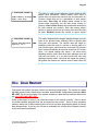
IV.H. COLD RESTART
Cold restart will perform the same function as removing backup power. The system will restart
with ALL memory clean. Note that time and date, along with ALL configuration parameters WILL
BE LOST. Do not use this option if the system contains any data that has not been retrieved for
use. ALL DATA WILL BE LOST.
Doing a cold restart is useful if you notice the counter is not working correctly. There is about
one million possible programs that can be keyed into the counter. Some of these programs
make no sense from a data collection point but we do not have programming space to prevent
them being entered. If you key one of these in accidentally the counter will not operate correctly
until a cold restart is performed.
Copyright © 2006
2001 High Leah Electronics, Inc.
ALL RIGHTS RESERVED
Inc.
ALL RIGHTS RESERVED
ADVANCED
KEYPAD
SELECTION
OPERATION
MODE
Page 27
Press 6 from the menu and the screen will show:
SELECT MENU OPTION:
Cold Restart
(_ _ _ _)
Press ENTER to select the option.
nF
Cold Restart Erases
All Memory Contents!
If you are SURE you want to do this, use the arrow keys to
toggle to Yes. Press ENTER.
ARE YOU SURE? No
**** Unicorn-L ****
The system has now been completely reset to the factory
defaults.
Doing Cold Restart..
SELECT MENU OPTION:
Start Collecting
(_ _ _ _)
0F
Copyright © 2006
2001 High Leah Electronics, Inc.
ALL RIGHTS RESERVED
Inc.
ALL RIGHTS RESERVED
ADVANCED
KEYPAD
SELECTION
OPERATION
MODE
Page 28
IV.I. MONITOR LANES
Monitor Lanes allows the real-time monitoring of lanes. This option is intended for the user to
monitor traffic to ensure the installation is working properly. Press 4 from the menu and the
display will show:
SELECT MENU OPTION:
Monitor Lanes
(_ _ _ _)
Press ENTER to select the option.
nF
IV.J. MONITORING RAW PER VEHICLE COLLECTION
The counter displays this when first waiting for a vehicle:
Waiting For Any
Vehicle...
As a vehicle crosses the installation, the display will show the vehicle as it crosses:
1:10:25:26
5 Axles
54mph A#9 S#9 #11 G#
19.5’ 4.8’ 41.3’
4.8’
Copyright © 2006
2001 High Leah Electronics, Inc.
ALL RIGHTS RESERVED
Inc.
ALL RIGHTS RESERVED
Indicates a vehicle passed in lane 1 at 10 o'clock. It had 5
axles, was going 54 miles per hour, and the spacing from the
first to the second axle was 12.8 feet. Note that only the first
axle spacing is displayed regardless of how many axles the
vehicle has (you can view other spacings by using the arrow
keys, see below).
ADVANCED
KEYPAD
SELECTION
OPERATION
MODE
Page 29
While monitoring, you may press the following keys:
CLEAR - Aborts and returns to the menu.
SPACE - Freezes the display. This allows you to view a vehicle for a longer period of time.
Press SPACE again to un-freeze the display.
Allows you to see other spacings. Press either arrow key again and the screen
will return to the original display. These keys work even when the Freeze Key (Space) has
been pressed.
If an asterisk character appears before the lane number, this indicates that collection has not
actually started yet, and the vehicles shown are not being stored in memory.
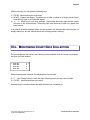
IV.K. MONITORING COUNT DATA COLLECTION
The counter displays the first four count lanes you have enabled. Note the counter only displays
the lanes you have enabled:
< Lane
Lane
Lane
Lane
#1:
#2:
#3:
#4:
0 >
0
0
0
While monitoring data collection, the following keys can be used:
0 - If just Testing Lanes (i.e. from the Start Collecting option) this key zeros all totals.
CLEAR - Aborts and returns to the menu.
An asterisk on the screen indicates that data collection has not started yet.
Copyright © 2006
2001 High Leah Electronics, Inc.
ALL RIGHTS RESERVED
Inc.
ALL RIGHTS RESERVED
ADVANCED
KEYPAD
SELECTION
OPERATION
MODE
Page 30
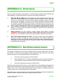
APPENDIX A. TROUBLE SHOOTING
This Section is intended as a guide towards installation trouble shooting. It is in no way intended
for the service or repair of any type of Apollo system.
Some basic problems can always occur during operation. Generally, they will be some small
error in setup or sensor installation. Listed are some basic problems and possible solutions. If
you cannot solve an installation problem, or if you find a new solution to an old problem, please
call Diamond Traffic Products. We are glad to help solve any type of installation problem or receive new installation information.
Problem
Tubes are installed to collect Raw or per vehicle, but errors keep occurring in data collection.
Solution
Are the tubes the same length? Are they stretched tight (both the same amount if using two per
lane) across the roadway? Are there holes in the tubes (you can check this by plugging the tube
and putting it under air pressure)? Is the end of the tube which is not being connected plugged
properly?
Problem
I've installed tubes to collect raw vehicle data, but I keep getting errors. I check the "Test Sensor"
option, and the tubes are functioning.
Solution
Are the tubes in the correct order? Remember, the tubes must be connected in sequence depending on your lane assignment and configuration. Check the Tables in Section II.a for conformation. You may have a lane installed backwards. Another possible problem is bi-directional traffic. Do you have the Directional Option enabled?
Problem
I have installed a Apollo in a busy roadway. The counter has stopped collecting data when I arrive. Everything seems to be working.
Solution
Check the Show Status option. Is the memory full? You may need to retrieve the data from the
counter more often.
Copyright © 2006 High Leah Electronics, Inc.
ALL RIGHTS RESERVED
APPENDIX
Page 31
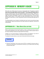
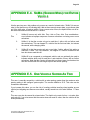
APPENDIX B. MEMORY USAGE
Each mode uses a different amount of memory for storing traffic data. This appendix is intended
to give the user an approximation of how long a Apollo Field Unit may collect data before retrieval must be performed. Note that this is only a guide it is recommended to retrieve data as
often as is practical from the units, and deleting retrieved files from the memory. Different configurations may store different amounts of data. For example, the amount of memory to store a
single 2 axle vehicle in Raw Mode is 7 bytes if you are using axle sensors, and 7 if you are using
presence sensors (loops). A 5 axle vehicle in the same mode will take 13 bytes if you are using
axle sensors, but still seven if you are using presence sensors (the individual axle lengths are not
stored).
The following tables give you formulas for calculating how much memory any particular storage
mode might take. Simply find the table that most closely matches your application, and follow the
steps described.
APPENDIX B.1. RAW DATA COLLECTION
Raw per vehicle data stores each individual vehicle in memory, therefore the amount of memory
used is directly dependent on how many vehicles pass the sensors. Another important factor is
the number of axles per vehicle (more axles require more memory).
Generally, you can use the average of 2.75 axles per vehicle for most highways. If your site differs from this, you may wish to increase or decrease the numbers given below.
To calculate how many vehicles you can store with the Apollo follow the below steps:
SENSOR CONFIGURATION
Axle-Axle
Divide the Total Memory of your counter minus 2000 (for overhead) by the base number of
bytes from the chart above. The total amount of memory in your counter can be found using
the Show Status option.
Copyright © 2006 High Leah Electronics, Inc.
ALL RIGHTS RESERVED
APPENDIX
Page 32
APPENDIX B.2. COUNT DATA COLLECTION
Count data stores the total number of vehicles that crossed the sensors for each 15 minutes period.
With the standard 8 megabytes of memory, recording four lanes on 15 minute intervals, the
counter should operate for an average of 8000 days.
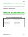
APPENDIX C. PLUGS & CONNECTORS
This section describes the physical hardware connections for connectors on the Unicorn Limited.
APOLLO 9 PIN FEMALE SERIAL INTERFACE CABLE
Unicorn Limited 9 Pin Connector
9 Pin Female Sub-D Connector
#1 – Receive Data (RXD)
#3 – Transmit Data (TXD)
#2 – Carrier Detect (DCD)
#4 – Data Terminal Ready (DTR)
#3 – Data Terminal Ready (DTR)
#6 – Data Set Ready (DSR)
#4 – Ready To Send (RTS)
#8 – Clear to Send (CTS)
#5 – Serial Port Enable (ENA)
#5 – Signal Ground (GND)
#6 – Signal Ground (GND)
(Shield)
#8 – Transmit Data
#2 – Receive Data (RXD)
#9 – Clear To Send (CTS)
#7 – Ready to Send (RTS)
Copyright © 2006 High Leah Electronics, Inc.
ALL RIGHTS RESERVED
#
APPENDIX
Page 33
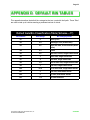
APPENDIX D. DEFAULT BIN TABLES
This appendix describes the default bins categories that are used with the Apollo. These "Bins"
are used to total up all vehicles meeting a predetermined set of criteria.
Default Axle Bin Classification Table (Scheme—’F’)
Bin Number
Axle Range
#1
2
#2
2-4
Passenger Cars (w/wo trailer)
#3
2-5
Other two axle, 4 tire vehicles (w/wo
trailer)
#4
2-3
Buses
#5
2-5
Two axle, six tire, single trailer trucks
#6
3
Three axle, single unit trucks
#7
4
Four axle, single unit trucks
#8
3-4
#9
5
#10
6-10
#11
5
Five axle, multi-trailer trucks
#12
6
Six axle, multi-trailer trucks
#13
7-13
Copyright © 2006 High Leah Electronics, Inc.
ALL RIGHTS RESERVED
Bin Category Name
Motorcycles
Four or less axle, single trailer trucks
Five axle, single trailer trucks
Six or more axle, single trailer trucks
All Other Vehicles
APPENDIX
Page 34
Default Speed & Length Bin Classification Table
Bin Number
Speed Range
Length Range
#1
0.0 - 19.9 mph
0.0 – 5.9 feet
#2
20.0 – 24.9 mph
6.0 – 10.0 feet
#3
25.0 – 29.9 mph
10.1 – 14.9 feet
#4
30.0 – 34.9 mph
15.0 – 19.9 feet
#5
35.0 – 39.9 mph
20.0 – 24.9 feet
#6
40.0 – 44.9 mph
25.0 – 29.9 feet
#7
45.0 – 49.9 mph
30.0 – 39.9 feet
#8
50.0 – 54.9 mph
40.0 – 49.9 feet
#9
55.0 – 59.9 mph
50.0 – 59.9 feet
#10
60.0 – 64.9 mph
60.0 – 69.9 feet
#11
65.0 – 69.9 mph
70.0 – 79.9 feet
#12
70.0 – 74.9 mph
80.0 – 89.9 feet
#13
75.0 – 79.9 mph
All Other Lengths
#14
80.0 – 84.9 mph
#15
85.0 – 89.9 mph
#16
All Other Speeds
Copyright © 2006 High Leah Electronics, Inc.
ALL RIGHTS RESERVED
APPENDIX
Page 35
APPENDIX E. ROAD TUBE PROBLEMS
& SOLUTIONS
This appendix discusses the various problems that road tubes can cause. Road tubes present
their own unique set of problems for automatic vehicle classifiers & counters. Being aware of
these potential problems before installing your road tubes can greatly reduce the frequency of
these problems.
This appendix divides each problem (or "error") into a separate section, and then lists the known
causes of the problem.
APPENDIX E.1. MISSED AXLES
Missed axles are the most frequent errors seen. They are caused, very simply, by the hardware
(airswitch) inside the counter not reporting an actuation of the road tube when there is one.
Some of the reasons for this are as follows:
Speed and Spacing. The airswitch in the Apollo is undoubtedly the best in the business,
however, even it is limited to 30 activations per second, or about 33ms per activation. If a
second strike of the road tube occurs faster than 33ms, then the airswitch will not report
the second activation.
Does this ever happen? Yes, take for example a car towing a 2 axle travel trailer at
65mph. A travel trailer typically has a spacing of 2.5ft between axles, and 65mph is
about 95 feet per second. Therefore, how long does it take between the first road tube
hit by the travel trailer, and the second. This is (2.5ft/(95ft/sec)) 26ms. The airswitch
would not report the second axle of the travel trailer and this axle would be missed by
the Apollo.
Lifted wheels. Some trucks have an optional axle which may be raised slightly off the
ground (to save on tread wear). The Apollo will probably miss it, but sometimes
it can
show up as an error if human observation data is being compared to the counter and
the observer is not aware that the wheel is lifted.
Bouncing Vehicles. Although uncommon, roads with dips or other irregular surface
features can cause some truck axles to bounce slightly. This can occasional lead to
missed axles. Note that the Apollo looks at both sets of road tube activations, so this
problem is minimized.
Improper Road Tubes or Installation. The type, length, and method of installation of
your road tubes can lead to increasing the number of missed axles; Always plug the end
of tube with a suitable device (unless the road tube is shorter than 25 feet, and then
DON'T plug it); always plug the road tube onto the counter nozzle all the way; always use
an approved brand, size, and type of material for all of your road tubes; don't over
Copyright © 2006 High Leah Electronics, Inc.
ALL RIGHTS RESERVED
APPENDIX
Page 36
stretch the road tubes because the diameter shrinks the more you stretch it.
Weak Signal With Longer Road Tubes. Very simply, the longer the road tube, the
farther the "sound" of an axle striking the road tube has to travel. Make sure you use road
tube lengths as recommended in the next section.
Sound Wave Interference.To understand why this is a problem, you should
understand that the Apollo airswitch (like all airswitches) uses a "sound wave" to detect
an axle hit. This wave is very similar to a water wave, in that it starts at a point and moves
down the road tube to the round piezo disk sensor in the airswitch. It travels down
the
road tube at the speed of sound, which is about 767 MPH at 20 degrees celsius, or 1125
feet per second. The force of this "wave" of sound bends the piezo disk in the counter
which causes a voltage spike to be generated. It is this voltage spike which the
Apollo
detects as an axle strike on the road tube.
The following example shows how very close axle hits (such as with tandem axles on a
truck) can actually interfere with each other and cause a missed axle.
1.
Assume you have a 50' road tube stretched across a single lane of traffic. The
road tube has been stretched 50" to make it tight. The end of the tube on the
roadway is plugged and the other end is plugged into a Apollo.
2.
A 5 axle single trailer truck traveling 55mph crosses the road tube.
3.
The first axle is detected with no problem.
4.
The second axle (the first axle of first tandem pair) hits the road tube. This causes
FOUR sound waves to be generated, TWO from each tire.
5.
The Left Tire will send two sound wave from it (1 in each direction) and the Right
Tire will send two wave from it as well. The sound waves look something like the
following:
<< A o B >>
<< C o D >>
(to Apollo)
Each Letter represents a sound wave and the arrow next to the letter shows the
direction the sound wave is traveling.
6.
At this point the following things will happen: Sound "A" will travel to the end of
the road tube and be absorbed by the plug. Sound "B" and "C" will travel towards
each other, collide, and be seriously weakened. Sound "D", however, will be
uninhibited and travel down the road tube towards the airswitch on the Unicorn
Limited. Since all of the sound waves except "D" have been destroyed, we will
only talk about sound wave "D" for the rest of this section, and it will be called the
Wave.
7.
The road tube has been stretched about 50", so it is now 54.16' long. Presuming
the truck is in the center of the lane (lane being 12' feet wide) and the truck is 8
feet wide, the Wave should start at the 44' mark.
8.
The Wave will travel down the road tube towards the Apollo and contact the
airswitch in about 39ms (ms stands for milliseconds, or thousandths of a second).
Copyright © 2006 High Leah Electronics, Inc.
ALL RIGHTS RESERVED
APPENDIX
Page 37
9.
After the Wave hits the airswitch, it will bounce back and return up the road tube
towards the vehicle. Thus, we have a weakened returning wave going back up
the road tube.
10.
The next axle on the truck hits the road tube about 56ms after the first (a 4.5ft
spacing typical, on a 55mph vehicle). Once again, another Sound Wave "D" is
generated and travels down the road tube towards the airswitch.
11.
At this point we have the following:
———- D2 >> —————- << D1 —————- Apollo
One wave traveling down, and one weaker wave returning. They will, of course,
collide into each other at some point in the road tube, weakening both waves so
that the second wave is too weak to register as an axle strike.
The question then becomes, if this is causing missed axles, why does a shorter road tube work
better? If you take a 30' road tube, stretch it 50". Sound Wave "D" will start at about the 24' mark,
and therefore will take only 21ms to reach the airswitch. Similarity, Sound Wave "D" will only take
21ms to return to the starting point (at the 24' mark). This makes the total time only 42ms for the
first Sound Wave "D" to strike the airswitch and return to the starting point. This time is BEFORE
the 56ms time it takes for the next axle to hit. Therefore, the first Sound Wave "D" is past the
point of origin and cannot interfere with the next axle strike.
In summary, you are better off using shorter road tubes for faster speed vehicles. You are also
better off using shorter road tubes for vehicles which have closer axle spacings (such as truck
tandem axles).To minimize missing axles and maximize accuracy we suggest using the following
road tube lengths:
Speed
Road Tube Length
—————————————————————
0-25mph
60 ft
26-35mph
50 ft
36-45mph
40 ft
46+
30 ft
While a shorter road tube at faster speeds is always more accurate, we do not suggest using
road tubes shorter than 30' due to the potential damage to an airswitch by very strong "sounds"
(or signals).
Copyright © 2006 High Leah Electronics, Inc.
ALL RIGHTS RESERVED
APPENDIX
Page 38
APPENDIX E.2. EXTRA AXLES
This error, while not frequent, does happen. It is almost always a problem with the actual road
tube installation, or with the road surface. Causes of extra axles are listed below:
will
Road Tube Bounce (Slap). Since the road tubes are made of flexible rubber, they move
when they are hit. Depending on how tightly they are stretched, how far apart the
anchors to the roadway are, and how heavy the vehicle crossing the tubes is, the road
tube may move only slightly, or may move a lot. When a tire hits the road tube normally,
the airswitch is activated by the sound of that tire. If the road tube is moved a lot, it will
return quickly enough to its original position and may "Slap" the road with enough force to
actually "sound" like another axle. This error is minimized by the fact that the airswitch
not re activate for at least 33ms, and the road tube should be stabilized by then (but not
always). You can also help this problem by taping the road tube to the road at short
Intervals along its length.
Rutted Pavement. DO NOT INSTALL ROAD TUBES OVER BADLY RUTTED
PAVEMENT. This will cause the road tube to bounce wildly when driven over by heavy
vehicles. If you must install the road tubes in rutted pavement, tape them down heavily.
Road Tubes Not Perpendicular to Traffic. This error (usually only at slow speeds) is
caused by a vehicle not hitting the road tubes squarely. If the vehicle is going slow
enough, the left tire (or tires) and the right tire (or tires) will cause an individual activation.
This problem is most commonly seen in intersections, where vehicles are turning across
the road tubes at slow speeds.
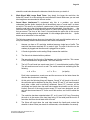
APPENDIX E.3. BAD SPEED AND/OR LENGTH
This problem is infrequent, but can occur sometimes when the counter misses axles. For example, assume a 2 axle, 8 foot axle spacing, vehicle traveling 60 mph crosses two road tubes
spaced 8 feet apart. The spacings and timings occurred as below:
1.
Road Tube #1 hit by first axle at 10:00:00.00000.
2.
Road Tube #2 and #1 hit almost simultaneously by first and second axles at
10:00:00.09090. Counter missed the Road Tube #2 hit (for whatever reason).
3.
Road Tube #2 hit by second axle at 10:00:00.18181.
Since the counter waits for the first hit on #1, and the first hit on #2 to determine the speed, the
speed will be determined by the second road tube #2 hit. This gives (8ft/.18181sec) 44ft/sec, or
30mph. This is only 1/2 the actual vehicle speed! Since the speed is calculated wrong, the
counter will also give an incorrect length value for the vehicle.
Note that this error is really caused by a missed axle, the only difference was that the Apollo was
still able to create a vehicle from the data, so it gave the values it could.
Copyright © 2006 High Leah Electronics, Inc.
ALL RIGHTS RESERVED
APPENDIX
Page 39
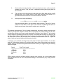
APPENDIX E.4. SNMIS (SENSOR MISS) FOR ENTIRE
VEHICLE
Like the previous error, this problem only occurs as a result of missed axles. "SnMis" (for sensor
miss) is the Apollo's way of indicating that it did not have enough sensor data, or got sensor data
not in the right order, to make a vehicle. Once a sensor miss occurs, the Apollo blocks out all further sensor activations on that lane for 1 second.
1.
SnMis #0 occurs only with Axle Pres Axle or Pres Axle Pres combinations.
error indicates a improper sequence of sensor activations or missing one or more
activations.
2.
SnMis #1 is that the counter only got a road tube 1 strike, with no further road
tube activations. This can happen if a vehicle hits the first road tube, but misses
the second, while changing lanes.
3.
SnMis #2 is that the counter only got a road tube 2 strike, without first getting a
road tube 1 strike. This, like SnMis #1, can happen if a vehicle crosses into the
lane but misses road tube #1.
4.
SnMis #3 is an overspeed or underspeed vehicle, and can optionally be used to
indicate vehicles which only hit road tube 1 and road tube 2 once, with no further
activations. Note that the counter will normally turn these types of activations into
two axle vehicles with the axle length equal to the sensor spacing.
This
APPENDIX E.5. ONE VEHICLE SHOWN AS TWO
This error is normally caused by a vehicle with an axle spacing greater than the maximum axle
spacing setting in the configure system option. The counter defaults to 35.0'. This value can be
increased or decreased.
If you increase this value, you run the risk of counting vehicles traveling close together as one
vehicle (two tailgating cars become one vehicle, usually turned into a four axle Scheme F Class
#8).
This error can also be caused by missed axles. The Apollo only resets its time out value after
each axle hit, if you miss some and the counter does not reset its value, then the vehicle will be
ended prematurely.
Copyright © 2006 High Leah Electronics, Inc.
ALL RIGHTS RESERVED
APPENDIX
Page 40
APPENDIX E.6. TWO VEHICLES SHOWN AS ONE
This is a rare occurrence if you have tailgating function enabled. If Tailgating is not enabled, this
will occur in vehicles that are following closer than the “maximum axle spacing”. This can be
more common in slower urban areas; in these application turning on the tailgating vehicles option is highly recommended.
APPENDIX E.7. ROAD TUBE SETUP THAT DOES
NOT CAUSE ERRORS
The following section describes various road tube issues which do not cause errors. This is included to dispel any suspicions about these issues causing problems.
Coiled road tubes. The effect of coiled road tubes versus non coiled road tubes does
not have a noticeable effect.
Copyright © 2006 High Leah Electronics, Inc.
ALL RIGHTS RESERVED
APPENDIX
Page 41
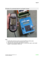
APPENDIX F.1. GPS SETUP
Copyright © 2006 High Leah Electronics, Inc.
ALL RIGHTS RESERVED
APPENDIX
Page 42
Copyright © 2006 High Leah Electronics, Inc.
ALL RIGHTS RESERVED
APPENDIX
Page 43
Copyright © 2006 High Leah Electronics, Inc.
ALL RIGHTS RESERVED
APPENDIX