1
HDL Designer SeriesTM User Manual
Software Version 2008.1
September 18, 2008
© 1996-2008 Mentor Graphics Corporation
All rights reserved.
This document contains information that is proprietary to Mentor Graphics Corporation. The original recipient of this
document may duplicate this document in whole or in part for internal business purposes only, provided that this entire
notice appears in all copies. In duplicating any part of this document, the recipient agrees to make every reasonable
effort to prevent the unauthorized use and distribution of the proprietary information.
This document is for information and instruction purposes. Mentor Graphics reserves the right to make
changes in specifications and other information contained in this publication without prior notice, and the
reader should, in all cases, consult Mentor Graphics to determine whether any changes have been
made.
The terms and conditions governing the sale and licensing of Mentor Graphics products are set forth in
written agreements between Mentor Graphics and its customers. No representation or other affirmation
of fact contained in this publication shall be deemed to be a warranty or give rise to any liability of Mentor
Graphics whatsoever.
MENTOR GRAPHICS MAKES NO WARRANTY OF ANY KIND WITH REGARD TO THIS MATERIAL
INCLUDING, BUT NOT LIMITED TO, THE IMPLIED WARRANTIES OF MERCHANTABILITY AND
FITNESS FOR A PARTICULAR PURPOSE.
MENTOR GRAPHICS SHALL NOT BE LIABLE FOR ANY INCIDENTAL, INDIRECT, SPECIAL, OR
CONSEQUENTIAL DAMAGES WHATSOEVER (INCLUDING BUT NOT LIMITED TO LOST PROFITS)
ARISING OUT OF OR RELATED TO THIS PUBLICATION OR THE INFORMATION CONTAINED IN IT,
EVEN IF MENTOR GRAPHICS CORPORATION HAS BEEN ADVISED OF THE POSSIBILITY OF
SUCH DAMAGES.
RESTRICTED RIGHTS LEGEND 03/97
U.S. Government Restricted Rights. The SOFTWARE and documentation have been developed entirely
at private expense and are commercial computer software provided with restricted rights. Use,
duplication or disclosure by the U.S. Government or a U.S. Government subcontractor is subject to the
restrictions set forth in the license agreement provided with the software pursuant to DFARS 227.72023(a) or as set forth in subparagraph (c)(1) and (2) of the Commercial Computer Software - Restricted
Rights clause at FAR 52.227-19, as applicable.
Contractor/manufacturer is:
Mentor Graphics Corporation
8005 S.W. Boeckman Road, Wilsonville, Oregon 97070-7777.
Telephone: 503.685.7000
Toll-Free Telephone: 800.592.2210
Website: www.mentor.com
SupportNet: supportnet.mentor.com/
Send Feedback on Documentation: supportnet.mentor.com/user/feedback_form.cfm
TRADEMARKS: The trademarks, logos and service marks ("Marks") used herein are the property of
Mentor Graphics Corporation or other third parties. No one is permitted to use these Marks without the
prior written consent of Mentor Graphics or the respective third-party owner. The use herein of a thirdparty Mark is not an attempt to indicate Mentor Graphics as a source of a product, but is intended to
indicate a product from, or associated with, a particular third party. A current list of Mentor Graphics’
trademarks may be viewed at: www.mentor.com/terms_conditions/trademarks.cfm.
Table of Contents
Chapter 1
Introduction. . . . . . . . . . . . . . . . . . . . . . . . . . . . . . . . . . . . . . . . . . . . . . . . . . . . . . . . . . . . . . .
Overview . . . . . . . . . . . . . . . . . . . . . . . . . . . . . . . . . . . . . . . . . . . . . . . . . . . . . . . . . . . . . . . .
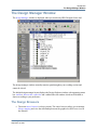
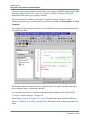
The Design Manager Window . . . . . . . . . . . . . . . . . . . . . . . . . . . . . . . . . . . . . . . . . . . . . . . .
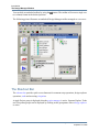
The Design Browsers . . . . . . . . . . . . . . . . . . . . . . . . . . . . . . . . . . . . . . . . . . . . . . . . . . . . .
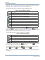
The LaunchPad . . . . . . . . . . . . . . . . . . . . . . . . . . . . . . . . . . . . . . . . . . . . . . . . . . . . . . . . . .
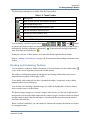
Changing the Design Manager Layout . . . . . . . . . . . . . . . . . . . . . . . . . . . . . . . . . . . . . . . .
The Menu Bar . . . . . . . . . . . . . . . . . . . . . . . . . . . . . . . . . . . . . . . . . . . . . . . . . . . . . . . . . . .
Toolbars . . . . . . . . . . . . . . . . . . . . . . . . . . . . . . . . . . . . . . . . . . . . . . . . . . . . . . . . . . . . . . .
Docking and Undocking Toolbars . . . . . . . . . . . . . . . . . . . . . . . . . . . . . . . . . . . . . . . . . .
The Shortcut Bar . . . . . . . . . . . . . . . . . . . . . . . . . . . . . . . . . . . . . . . . . . . . . . . . . . . . . . . . .
Keyboard Shortcuts. . . . . . . . . . . . . . . . . . . . . . . . . . . . . . . . . . . . . . . . . . . . . . . . . . . . . . .
Menu Accelerator Keys . . . . . . . . . . . . . . . . . . . . . . . . . . . . . . . . . . . . . . . . . . . . . . . . . .
Dialog Box Shortcuts . . . . . . . . . . . . . . . . . . . . . . . . . . . . . . . . . . . . . . . . . . . . . . . . . . . .
Mouse Buttons . . . . . . . . . . . . . . . . . . . . . . . . . . . . . . . . . . . . . . . . . . . . . . . . . . . . . . . . .
Status Bar . . . . . . . . . . . . . . . . . . . . . . . . . . . . . . . . . . . . . . . . . . . . . . . . . . . . . . . . . . . . . .
Object Tips . . . . . . . . . . . . . . . . . . . . . . . . . . . . . . . . . . . . . . . . . . . . . . . . . . . . . . . . . . . . .
File Browser . . . . . . . . . . . . . . . . . . . . . . . . . . . . . . . . . . . . . . . . . . . . . . . . . . . . . . . . . . . .
Directory Browser. . . . . . . . . . . . . . . . . . . . . . . . . . . . . . . . . . . . . . . . . . . . . . . . . . . . . . . .
HTML Browser. . . . . . . . . . . . . . . . . . . . . . . . . . . . . . . . . . . . . . . . . . . . . . . . . . . . . . . . . .
Editor Windows . . . . . . . . . . . . . . . . . . . . . . . . . . . . . . . . . . . . . . . . . . . . . . . . . . . . . . . . .
Log Window . . . . . . . . . . . . . . . . . . . . . . . . . . . . . . . . . . . . . . . . . . . . . . . . . . . . . . . . . . . . .
Log Window Toolbar . . . . . . . . . . . . . . . . . . . . . . . . . . . . . . . . . . . . . . . . . . . . . . . . . . . . .
Console Log . . . . . . . . . . . . . . . . . . . . . . . . . . . . . . . . . . . . . . . . . . . . . . . . . . . . . . . . . . . .
Task Log . . . . . . . . . . . . . . . . . . . . . . . . . . . . . . . . . . . . . . . . . . . . . . . . . . . . . . . . . . . . . . .
Batch Command Language. . . . . . . . . . . . . . . . . . . . . . . . . . . . . . . . . . . . . . . . . . . . . . . . .
Command Files. . . . . . . . . . . . . . . . . . . . . . . . . . . . . . . . . . . . . . . . . . . . . . . . . . . . . . . . .
Closing Windows and Exiting HDS . . . . . . . . . . . . . . . . . . . . . . . . . . . . . . . . . . . . . . . . . . .
19
19
21
21
22
23
24
24
27
28
31
32
32
32
32
33
33
34
34
35
36
36
37
39
40
40
42
Chapter 2
Library Mapping . . . . . . . . . . . . . . . . . . . . . . . . . . . . . . . . . . . . . . . . . . . . . . . . . . . . . . . . . .
Projects and Libraries . . . . . . . . . . . . . . . . . . . . . . . . . . . . . . . . . . . . . . . . . . . . . . . . . . . . . .
Project Manager Notation . . . . . . . . . . . . . . . . . . . . . . . . . . . . . . . . . . . . . . . . . . . . . . . . . . .
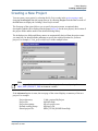
Creating a New Project . . . . . . . . . . . . . . . . . . . . . . . . . . . . . . . . . . . . . . . . . . . . . . . . . . . . .
Setting the Shared Project File . . . . . . . . . . . . . . . . . . . . . . . . . . . . . . . . . . . . . . . . . . . . . .
Editing the Project Description. . . . . . . . . . . . . . . . . . . . . . . . . . . . . . . . . . . . . . . . . . . . . .
Editing the Library Search Path . . . . . . . . . . . . . . . . . . . . . . . . . . . . . . . . . . . . . . . . . . . . .
Locating Implicit Include Files. . . . . . . . . . . . . . . . . . . . . . . . . . . . . . . . . . . . . . . . . . . . . .
Opening and Closing Projects . . . . . . . . . . . . . . . . . . . . . . . . . . . . . . . . . . . . . . . . . . . . . . . .
Copying a Project File . . . . . . . . . . . . . . . . . . . . . . . . . . . . . . . . . . . . . . . . . . . . . . . . . . . . . .
Copying a Library between Projects . . . . . . . . . . . . . . . . . . . . . . . . . . . . . . . . . . . . . . . . . . .
Editing Shared Project Libraries . . . . . . . . . . . . . . . . . . . . . . . . . . . . . . . . . . . . . . . . . . . . . .
45
45
48
49
52
53
54
54
55
56
57
57
HDL Designer Series User Manual, V2008.1
September 18, 2008
3
Table of Contents
Refreshing the Project Manager View. . . . . . . . . . . . . . . . . . . . . . . . . . . . . . . . . . . . . . . . . .
Creating a Library Mapping. . . . . . . . . . . . . . . . . . . . . . . . . . . . . . . . . . . . . . . . . . . . . . . . . .
Example on Creating a Library . . . . . . . . . . . . . . . . . . . . . . . . . . . . . . . . . . . . . . . . . . . .
Using the Library Creation Wizard. . . . . . . . . . . . . . . . . . . . . . . . . . . . . . . . . . . . . . . . . . .
Accessing the Library Creation wizard . . . . . . . . . . . . . . . . . . . . . . . . . . . . . . . . . . . . . .
Specifying Library Details . . . . . . . . . . . . . . . . . . . . . . . . . . . . . . . . . . . . . . . . . . . . . . . .
Specifying Downstream Mappings . . . . . . . . . . . . . . . . . . . . . . . . . . . . . . . . . . . . . . . . .
Specifying Library Options . . . . . . . . . . . . . . . . . . . . . . . . . . . . . . . . . . . . . . . . . . . . . . .
Specifying Version Management Mappings . . . . . . . . . . . . . . . . . . . . . . . . . . . . . . . . . .
Editing Shared Library Mappings. . . . . . . . . . . . . . . . . . . . . . . . . . . . . . . . . . . . . . . . . . . .
Editing Library Mapping . . . . . . . . . . . . . . . . . . . . . . . . . . . . . . . . . . . . . . . . . . . . . . . . . .
Adding Downstream Library Mappings . . . . . . . . . . . . . . . . . . . . . . . . . . . . . . . . . . . . . . .
Default Downstream Library Mapping . . . . . . . . . . . . . . . . . . . . . . . . . . . . . . . . . . . . . .
Changing the Library Type. . . . . . . . . . . . . . . . . . . . . . . . . . . . . . . . . . . . . . . . . . . . . . . . .
Changing the Library Display Order . . . . . . . . . . . . . . . . . . . . . . . . . . . . . . . . . . . . . . . . .
Setting the Default Library . . . . . . . . . . . . . . . . . . . . . . . . . . . . . . . . . . . . . . . . . . . . . . . . .
Adding a Verilog Include Search Path . . . . . . . . . . . . . . . . . . . . . . . . . . . . . . . . . . . . . . . .
57
57
58
59
59
59
63
65
66
67
67
68
69
69
70
70
70
Chapter 3
Design Browsing . . . . . . . . . . . . . . . . . . . . . . . . . . . . . . . . . . . . . . . . . . . . . . . . . . . . . . . . . . .
Using Design Explorers . . . . . . . . . . . . . . . . . . . . . . . . . . . . . . . . . . . . . . . . . . . . . . . . . . . . .
Showing Hierarchy . . . . . . . . . . . . . . . . . . . . . . . . . . . . . . . . . . . . . . . . . . . . . . . . . . . . . . .
Setting the Default View. . . . . . . . . . . . . . . . . . . . . . . . . . . . . . . . . . . . . . . . . . . . . . . . . . .
Highlighting Design Objects. . . . . . . . . . . . . . . . . . . . . . . . . . . . . . . . . . . . . . . . . . . . . . . .
Indicating the Top of a Design . . . . . . . . . . . . . . . . . . . . . . . . . . . . . . . . . . . . . . . . . . . . . .
Setting the Design Root . . . . . . . . . . . . . . . . . . . . . . . . . . . . . . . . . . . . . . . . . . . . . . . . . . .
Changing the Design Explorer Display Mode . . . . . . . . . . . . . . . . . . . . . . . . . . . . . . . . . .
Design Units Mode. . . . . . . . . . . . . . . . . . . . . . . . . . . . . . . . . . . . . . . . . . . . . . . . . . . . . .
Files Mode . . . . . . . . . . . . . . . . . . . . . . . . . . . . . . . . . . . . . . . . . . . . . . . . . . . . . . . . . . . .
Logical Objects Mode . . . . . . . . . . . . . . . . . . . . . . . . . . . . . . . . . . . . . . . . . . . . . . . . . . .
Using Viewpoints . . . . . . . . . . . . . . . . . . . . . . . . . . . . . . . . . . . . . . . . . . . . . . . . . . . . . . . .
Changing the Design Explorer Layout . . . . . . . . . . . . . . . . . . . . . . . . . . . . . . . . . . . . . . .
Changing the Displayed Columns . . . . . . . . . . . . . . . . . . . . . . . . . . . . . . . . . . . . . . . . . .
Changing the Column Display Order . . . . . . . . . . . . . . . . . . . . . . . . . . . . . . . . . . . . . . . .
Changing the Object Row Display Order. . . . . . . . . . . . . . . . . . . . . . . . . . . . . . . . . . . . .
Filtering Design Objects. . . . . . . . . . . . . . . . . . . . . . . . . . . . . . . . . . . . . . . . . . . . . . . . . .
Grouping Design Objects . . . . . . . . . . . . . . . . . . . . . . . . . . . . . . . . . . . . . . . . . . . . . . . . .
Adding a Viewpoint Shortcut. . . . . . . . . . . . . . . . . . . . . . . . . . . . . . . . . . . . . . . . . . . . . .
Finding Design Objects. . . . . . . . . . . . . . . . . . . . . . . . . . . . . . . . . . . . . . . . . . . . . . . . . . . .
Quick Find Shortcut . . . . . . . . . . . . . . . . . . . . . . . . . . . . . . . . . . . . . . . . . . . . . . . . . . . . .
Finding Unparsed Files . . . . . . . . . . . . . . . . . . . . . . . . . . . . . . . . . . . . . . . . . . . . . . . . . . . .
Finding Unbound Components . . . . . . . . . . . . . . . . . . . . . . . . . . . . . . . . . . . . . . . . . . . . . .
Disabling Downstream Operations . . . . . . . . . . . . . . . . . . . . . . . . . . . . . . . . . . . . . . . . . . .
Selecting and Unselecting Objects . . . . . . . . . . . . . . . . . . . . . . . . . . . . . . . . . . . . . . . . . . .
Moving Objects. . . . . . . . . . . . . . . . . . . . . . . . . . . . . . . . . . . . . . . . . . . . . . . . . . . . . . . . . .
Copying Objects . . . . . . . . . . . . . . . . . . . . . . . . . . . . . . . . . . . . . . . . . . . . . . . . . . . . . . . . .
Renaming Objects. . . . . . . . . . . . . . . . . . . . . . . . . . . . . . . . . . . . . . . . . . . . . . . . . . . . . . . .
Deleting Objects . . . . . . . . . . . . . . . . . . . . . . . . . . . . . . . . . . . . . . . . . . . . . . . . . . . . . . . . .
73
74
75
76
77
78
79
80
80
80
83
85
87
87
90
90
91
95
96
98
100
100
101
102
104
104
106
108
108
4
HDL Designer Series User Manual, V2008.1
September 18, 2008
Table of Contents
Deleting From Disk . . . . . . . . . . . . . . . . . . . . . . . . . . . . . . . . . . . . . . . . . . . . . . . . . . . . .
Hierarchical Deleting from Disk . . . . . . . . . . . . . . . . . . . . . . . . . . . . . . . . . . . . . . . . . . .
Deleting Graphics from Disk . . . . . . . . . . . . . . . . . . . . . . . . . . . . . . . . . . . . . . . . . . . . . .
Delete Special Options Dialog . . . . . . . . . . . . . . . . . . . . . . . . . . . . . . . . . . . . . . . . . . . . .
Delete from Disk Dialog . . . . . . . . . . . . . . . . . . . . . . . . . . . . . . . . . . . . . . . . . . . . . . . . .
Reporting Object References . . . . . . . . . . . . . . . . . . . . . . . . . . . . . . . . . . . . . . . . . . . . . . .
Updating Object References . . . . . . . . . . . . . . . . . . . . . . . . . . . . . . . . . . . . . . . . . . . . . . . .
Setting an Include File . . . . . . . . . . . . . . . . . . . . . . . . . . . . . . . . . . . . . . . . . . . . . . . . . . . .
Importing a Gate Level File . . . . . . . . . . . . . . . . . . . . . . . . . . . . . . . . . . . . . . . . . . . . . . . .
Setting a Gate Level File. . . . . . . . . . . . . . . . . . . . . . . . . . . . . . . . . . . . . . . . . . . . . . . . . . .
Editing View Properties . . . . . . . . . . . . . . . . . . . . . . . . . . . . . . . . . . . . . . . . . . . . . . . . . . .
Simulation Properties . . . . . . . . . . . . . . . . . . . . . . . . . . . . . . . . . . . . . . . . . . . . . . . . . . . .
Synthesis Properties . . . . . . . . . . . . . . . . . . . . . . . . . . . . . . . . . . . . . . . . . . . . . . . . . . . . .
Plug-in Settings . . . . . . . . . . . . . . . . . . . . . . . . . . . . . . . . . . . . . . . . . . . . . . . . . . . . . . . .
User Properties . . . . . . . . . . . . . . . . . . . . . . . . . . . . . . . . . . . . . . . . . . . . . . . . . . . . . . . . .
Add File Dialog. . . . . . . . . . . . . . . . . . . . . . . . . . . . . . . . . . . . . . . . . . . . . . . . . . . . . . . . . .
Opening Views from the Design Explorer . . . . . . . . . . . . . . . . . . . . . . . . . . . . . . . . . . . . .
Viewing the Generated HDL . . . . . . . . . . . . . . . . . . . . . . . . . . . . . . . . . . . . . . . . . . . . . . .
Adding Libraries to a Design Explorer. . . . . . . . . . . . . . . . . . . . . . . . . . . . . . . . . . . . . . . .
Refreshing a Design Explorer Window . . . . . . . . . . . . . . . . . . . . . . . . . . . . . . . . . . . . . . .
Design Explorer Notation . . . . . . . . . . . . . . . . . . . . . . . . . . . . . . . . . . . . . . . . . . . . . . . . . .
Using the Side Data Browser. . . . . . . . . . . . . . . . . . . . . . . . . . . . . . . . . . . . . . . . . . . . . . . . .
Side Data Browser Notation . . . . . . . . . . . . . . . . . . . . . . . . . . . . . . . . . . . . . . . . . . . . . . . .
Using the Downstream Browser . . . . . . . . . . . . . . . . . . . . . . . . . . . . . . . . . . . . . . . . . . . . . .
Downstream Browser Notation. . . . . . . . . . . . . . . . . . . . . . . . . . . . . . . . . . . . . . . . . . . . . .
Using the DesignPad Editor. . . . . . . . . . . . . . . . . . . . . . . . . . . . . . . . . . . . . . . . . . . . . . . . . .
Using the Component Browser . . . . . . . . . . . . . . . . . . . . . . . . . . . . . . . . . . . . . . . . . . . . . . .
109
110
110
111
112
114
115
117
117
119
119
120
121
122
123
124
124
125
125
125
125
128
131
131
133
133
134
Chapter 4
Design Views . . . . . . . . . . . . . . . . . . . . . . . . . . . . . . . . . . . . . . . . . . . . . . . . . . . . . . . . . . . . . .
Creating Design Views . . . . . . . . . . . . . . . . . . . . . . . . . . . . . . . . . . . . . . . . . . . . . . . . . . . . .
Creating a Design View by Opening Down . . . . . . . . . . . . . . . . . . . . . . . . . . . . . . . . . . . .
Using the Design Content Creation Wizard. . . . . . . . . . . . . . . . . . . . . . . . . . . . . . . . . . . . . .
Invoking the Design Content Creation Wizard. . . . . . . . . . . . . . . . . . . . . . . . . . . . . . . . . .
Creating a Document View. . . . . . . . . . . . . . . . . . . . . . . . . . . . . . . . . . . . . . . . . . . . . . . . .
Creating a Graphical View . . . . . . . . . . . . . . . . . . . . . . . . . . . . . . . . . . . . . . . . . . . . . . . .
Creating a HDL Text View . . . . . . . . . . . . . . . . . . . . . . . . . . . . . . . . . . . . . . . . . . . . . . .
Creating a Template View . . . . . . . . . . . . . . . . . . . . . . . . . . . . . . . . . . . . . . . . . . . . . . . . .
Using the Template Manager. . . . . . . . . . . . . . . . . . . . . . . . . . . . . . . . . . . . . . . . . . . . . . . . .
Editing Team Templates . . . . . . . . . . . . . . . . . . . . . . . . . . . . . . . . . . . . . . . . . . . . . . . . . . .
HDL Text Templates . . . . . . . . . . . . . . . . . . . . . . . . . . . . . . . . . . . . . . . . . . . . . . . . . . . . . . .
Default Templates. . . . . . . . . . . . . . . . . . . . . . . . . . . . . . . . . . . . . . . . . . . . . . . . . . . . . . . .
VHDL Architecture . . . . . . . . . . . . . . . . . . . . . . . . . . . . . . . . . . . . . . . . . . . . . . . . . . . . .
VHDL Combined . . . . . . . . . . . . . . . . . . . . . . . . . . . . . . . . . . . . . . . . . . . . . . . . . . . . . . .
VHDL Entity . . . . . . . . . . . . . . . . . . . . . . . . . . . . . . . . . . . . . . . . . . . . . . . . . . . . . . . . . .
VHDL Package Header . . . . . . . . . . . . . . . . . . . . . . . . . . . . . . . . . . . . . . . . . . . . . . . . . .
VHDL Package Body . . . . . . . . . . . . . . . . . . . . . . . . . . . . . . . . . . . . . . . . . . . . . . . . . . . .
VHDL Configuration . . . . . . . . . . . . . . . . . . . . . . . . . . . . . . . . . . . . . . . . . . . . . . . . . . . .
137
137
138
139
139
140
140
143
146
149
150
150
151
151
151
152
152
152
153
HDL Designer Series User Manual, V2008.1
September 18, 2008
5
Table of Contents
Verilog Module . . . . . . . . . . . . . . . . . . . . . . . . . . . . . . . . . . . . . . . . . . . . . . . . . . . . . . . .
Verilog Include. . . . . . . . . . . . . . . . . . . . . . . . . . . . . . . . . . . . . . . . . . . . . . . . . . . . . . . . .
Registered Views . . . . . . . . . . . . . . . . . . . . . . . . . . . . . . . . . . . . . . . . . . . . . . . . . . . . . . .
Updating the Interface to a HDL Text View . . . . . . . . . . . . . . . . . . . . . . . . . . . . . . . . . . .
Entering Comments in HDL Text View Headers. . . . . . . . . . . . . . . . . . . . . . . . . . . . . . .
Using Internal Variables . . . . . . . . . . . . . . . . . . . . . . . . . . . . . . . . . . . . . . . . . . . . . . . . . . . .
Using View Property Variables . . . . . . . . . . . . . . . . . . . . . . . . . . . . . . . . . . . . . . . . . . . . . . .
Evaluating View Property Variables . . . . . . . . . . . . . . . . . . . . . . . . . . . . . . . . . . . . . . . . .
VHDL Configurations . . . . . . . . . . . . . . . . . . . . . . . . . . . . . . . . . . . . . . . . . . . . . . . . . . . . . .
Setting Embedded VHDL Configuration Options . . . . . . . . . . . . . . . . . . . . . . . . . . . . . . .
Setting Standalone VHDL Configuration Options . . . . . . . . . . . . . . . . . . . . . . . . . . . . . . .
Generating a VHDL Configuration File . . . . . . . . . . . . . . . . . . . . . . . . . . . . . . . . . . . . . . .
Opening Design Unit Views . . . . . . . . . . . . . . . . . . . . . . . . . . . . . . . . . . . . . . . . . . . . . . . . .
153
153
154
154
155
156
157
158
159
159
160
162
164
Chapter 5
Adding/Removing Existing Design Content . . . . . . . . . . . . . . . . . . . . . . . . . . . . . . . . . . . . .
Adding Existing Design Content to a Project . . . . . . . . . . . . . . . . . . . . . . . . . . . . . . . . . . . .
What is an HDS Library . . . . . . . . . . . . . . . . . . . . . . . . . . . . . . . . . . . . . . . . . . . . . . . . . . .
What is an HDS Library Mode . . . . . . . . . . . . . . . . . . . . . . . . . . . . . . . . . . . . . . . . . . . . . .
How HDS Identifies Library Mappings . . . . . . . . . . . . . . . . . . . . . . . . . . . . . . . . . . . . . . .
Initial Guessing of HDL Mappings . . . . . . . . . . . . . . . . . . . . . . . . . . . . . . . . . . . . . . . . .
Refining Initial HDL Mapping Guess . . . . . . . . . . . . . . . . . . . . . . . . . . . . . . . . . . . . . . .
Inventing Library Names for Unmapped Directories. . . . . . . . . . . . . . . . . . . . . . . . . . . .
Processing of Library associations . . . . . . . . . . . . . . . . . . . . . . . . . . . . . . . . . . . . . . . . . .
Library Mapping Error Conditions Generation . . . . . . . . . . . . . . . . . . . . . . . . . . . . . . . .
Add Existing Design Wizard . . . . . . . . . . . . . . . . . . . . . . . . . . . . . . . . . . . . . . . . . . . . . . .
Accessing the Add Existing Design wizard . . . . . . . . . . . . . . . . . . . . . . . . . . . . . . . . . . .
Using the Add Existing Design Wizard . . . . . . . . . . . . . . . . . . . . . . . . . . . . . . . . . . . . . .
Related Topics . . . . . . . . . . . . . . . . . . . . . . . . . . . . . . . . . . . . . . . . . . . . . . . . . . . . . . . . .
Pointing to Design Content to be added to Project . . . . . . . . . . . . . . . . . . . . . . . . . . . . . . .
Setting HDL Mappings . . . . . . . . . . . . . . . . . . . . . . . . . . . . . . . . . . . . . . . . . . . . . . . . . . . .
Add Existing Design Wizard-HDL Mappings Page . . . . . . . . . . . . . . . . . . . . . . . . . . . .
Mapping Unmapped Directories . . . . . . . . . . . . . . . . . . . . . . . . . . . . . . . . . . . . . . . . . . .
Add Existing Design-HDS and Downstream Mappings Page . . . . . . . . . . . . . . . . . . . . .
Copying Specified Design Content. . . . . . . . . . . . . . . . . . . . . . . . . . . . . . . . . . . . . . . . . . .
Setting Missing Mappings . . . . . . . . . . . . . . . . . . . . . . . . . . . . . . . . . . . . . . . . . . . . . . . . .
Editing Library Mappings. . . . . . . . . . . . . . . . . . . . . . . . . . . . . . . . . . . . . . . . . . . . . . . . . .
Setting Target Libraries . . . . . . . . . . . . . . . . . . . . . . . . . . . . . . . . . . . . . . . . . . . . . . . . . . .
Setting Target Directories . . . . . . . . . . . . . . . . . . . . . . . . . . . . . . . . . . . . . . . . . . . . . . . . . .
Adding Design Files to a Library. . . . . . . . . . . . . . . . . . . . . . . . . . . . . . . . . . . . . . . . . . . . . .
Add Existing Files to Library Dialog . . . . . . . . . . . . . . . . . . . . . . . . . . . . . . . . . . . . . . . . .
Accessing the Add Existing Design Files dialog . . . . . . . . . . . . . . . . . . . . . . . . . . . . . . .
Related Topics . . . . . . . . . . . . . . . . . . . . . . . . . . . . . . . . . . . . . . . . . . . . . . . . . . . . . . . . .
Adding Files to a Library by taking a Copy of the Original Files . . . . . . . . . . . . . . . . . . .
Prerequisites . . . . . . . . . . . . . . . . . . . . . . . . . . . . . . . . . . . . . . . . . . . . . . . . . . . . . . . . . . .
Procedure . . . . . . . . . . . . . . . . . . . . . . . . . . . . . . . . . . . . . . . . . . . . . . . . . . . . . . . . . . . . .
Adding Files to a Library by Pointing to them in their Existing Location . . . . . . . . . . . . .
Prerequisites . . . . . . . . . . . . . . . . . . . . . . . . . . . . . . . . . . . . . . . . . . . . . . . . . . . . . . . . . . .
165
165
165
166
166
167
168
168
168
168
168
169
170
171
172
173
173
175
176
177
178
179
180
181
182
183
183
185
185
185
185
186
186
6
HDL Designer Series User Manual, V2008.1
September 18, 2008
Table of Contents
Procedure . . . . . . . . . . . . . . . . . . . . . . . . . . . . . . . . . . . . . . . . . . . . . . . . . . . . . . . . . . . . .
Removing Design Content. . . . . . . . . . . . . . . . . . . . . . . . . . . . . . . . . . . . . . . . . . . . . . . . . . .
Removing Design Files from a Project. . . . . . . . . . . . . . . . . . . . . . . . . . . . . . . . . . . . . . . .
Prerequisites . . . . . . . . . . . . . . . . . . . . . . . . . . . . . . . . . . . . . . . . . . . . . . . . . . . . . . . . . . .
Procedure . . . . . . . . . . . . . . . . . . . . . . . . . . . . . . . . . . . . . . . . . . . . . . . . . . . . . . . . . . . . .
Related Topics . . . . . . . . . . . . . . . . . . . . . . . . . . . . . . . . . . . . . . . . . . . . . . . . . . . . . . . . .
Reference Files. . . . . . . . . . . . . . . . . . . . . . . . . . . . . . . . . . . . . . . . . . . . . . . . . . . . . . . . . . . .
Creating Reference Files . . . . . . . . . . . . . . . . . . . . . . . . . . . . . . . . . . . . . . . . . . . . . . . . .
Editing Reference Files . . . . . . . . . . . . . . . . . . . . . . . . . . . . . . . . . . . . . . . . . . . . . . . . . .
Reference Files Limitations . . . . . . . . . . . . . . . . . . . . . . . . . . . . . . . . . . . . . . . . . . . . . . .
186
186
187
187
187
187
187
188
188
188
Chapter 6
Printing Views . . . . . . . . . . . . . . . . . . . . . . . . . . . . . . . . . . . . . . . . . . . . . . . . . . . . . . . . . . . . .
Printing Design Object Views . . . . . . . . . . . . . . . . . . . . . . . . . . . . . . . . . . . . . . . . . . . . . . . .
Printing Hierarchical Views. . . . . . . . . . . . . . . . . . . . . . . . . . . . . . . . . . . . . . . . . . . . . . . . . .
Choosing the Hierarchy for Print. . . . . . . . . . . . . . . . . . . . . . . . . . . . . . . . . . . . . . . . . . . . . .
Setting Page Display and Print Options. . . . . . . . . . . . . . . . . . . . . . . . . . . . . . . . . . . . . . . . .
Setting a Custom Paper Size . . . . . . . . . . . . . . . . . . . . . . . . . . . . . . . . . . . . . . . . . . . . . . . .
Setting Page Boundaries . . . . . . . . . . . . . . . . . . . . . . . . . . . . . . . . . . . . . . . . . . . . . . . . . . .
Setting Print Options for Block Diagram and IBD Views . . . . . . . . . . . . . . . . . . . . . . . . .
Page Break Preview . . . . . . . . . . . . . . . . . . . . . . . . . . . . . . . . . . . . . . . . . . . . . . . . . . . . . .
Printing a Page . . . . . . . . . . . . . . . . . . . . . . . . . . . . . . . . . . . . . . . . . . . . . . . . . . . . . . . . . .
Viewing a Page . . . . . . . . . . . . . . . . . . . . . . . . . . . . . . . . . . . . . . . . . . . . . . . . . . . . . . . . . .
Printing Text Views . . . . . . . . . . . . . . . . . . . . . . . . . . . . . . . . . . . . . . . . . . . . . . . . . . . . . . . .
Enscript Print Utility . . . . . . . . . . . . . . . . . . . . . . . . . . . . . . . . . . . . . . . . . . . . . . . . . . . . . .
Setting the Text File Print Command . . . . . . . . . . . . . . . . . . . . . . . . . . . . . . . . . . . . . . . . .
191
191
193
193
194
196
197
198
202
202
202
203
203
204
Chapter 7
Documentation and Visualization . . . . . . . . . . . . . . . . . . . . . . . . . . . . . . . . . . . . . . . . . . . . .
Documenting Design Object Views. . . . . . . . . . . . . . . . . . . . . . . . . . . . . . . . . . . . . . . . . . . .
Exporting HTML Documentation . . . . . . . . . . . . . . . . . . . . . . . . . . . . . . . . . . . . . . . . . . . . .
Configuring the Default HTML Documentation Settings . . . . . . . . . . . . . . . . . . . . . . . . .
Setting a Custom Image Size . . . . . . . . . . . . . . . . . . . . . . . . . . . . . . . . . . . . . . . . . . . . . .
Viewing Exported HTML Documentation . . . . . . . . . . . . . . . . . . . . . . . . . . . . . . . . . . . . .
Navigation Frame . . . . . . . . . . . . . . . . . . . . . . . . . . . . . . . . . . . . . . . . . . . . . . . . . . . . . . .
Design Frame . . . . . . . . . . . . . . . . . . . . . . . . . . . . . . . . . . . . . . . . . . . . . . . . . . . . . . . . . .
Deleting Exported HTML Documentation . . . . . . . . . . . . . . . . . . . . . . . . . . . . . . . . . . . . .
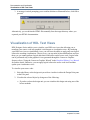
Visualization of HDL Text Views . . . . . . . . . . . . . . . . . . . . . . . . . . . . . . . . . . . . . . . . . . . . .
Visualizing Graphical Views Hierarchically . . . . . . . . . . . . . . . . . . . . . . . . . . . . . . . . . .
Viewing Visualization Views . . . . . . . . . . . . . . . . . . . . . . . . . . . . . . . . . . . . . . . . . . . . . . .
Updating Visualization Views . . . . . . . . . . . . . . . . . . . . . . . . . . . . . . . . . . . . . . . . . . . . . .
Highlighting Design Objects Related to Visualizations . . . . . . . . . . . . . . . . . . . . . . . . . . .
Deleting Visualization Views . . . . . . . . . . . . . . . . . . . . . . . . . . . . . . . . . . . . . . . . . . . . . . .
Delete Special. . . . . . . . . . . . . . . . . . . . . . . . . . . . . . . . . . . . . . . . . . . . . . . . . . . . . . . . . .
Configuring the Default Visualization Settings . . . . . . . . . . . . . . . . . . . . . . . . . . . . . . . . .
Managing Visualization Views. . . . . . . . . . . . . . . . . . . . . . . . . . . . . . . . . . . . . . . . . . . . . .
Creating Visualization Views for Child Components . . . . . . . . . . . . . . . . . . . . . . . . . . .
Opening Source Code of Visualization View . . . . . . . . . . . . . . . . . . . . . . . . . . . . . . . . .
207
207
207
211
220
221
222
223
229
230
238
239
240
242
243
243
244
247
247
248
HDL Designer Series User Manual, V2008.1
September 18, 2008
7
Table of Contents
Converting Visualization to Graphical View . . . . . . . . . . . . . . . . . . . . . . . . . . . . . . . . . . . 251
Chapter 8
Tasks, Tools and Flows. . . . . . . . . . . . . . . . . . . . . . . . . . . . . . . . . . . . . . . . . . . . . . . . . . . . . .
Using the Task Manager . . . . . . . . . . . . . . . . . . . . . . . . . . . . . . . . . . . . . . . . . . . . . . . . . . . .
Editing Team Tasks . . . . . . . . . . . . . . . . . . . . . . . . . . . . . . . . . . . . . . . . . . . . . . . . . . . . . .
Creating a Tool Task. . . . . . . . . . . . . . . . . . . . . . . . . . . . . . . . . . . . . . . . . . . . . . . . . . . . . .
Invoking a Program or Shell Script . . . . . . . . . . . . . . . . . . . . . . . . . . . . . . . . . . . . . . . . .
Using a Tcl Plug-in. . . . . . . . . . . . . . . . . . . . . . . . . . . . . . . . . . . . . . . . . . . . . . . . . . . . . .
Using a Tcl Script. . . . . . . . . . . . . . . . . . . . . . . . . . . . . . . . . . . . . . . . . . . . . . . . . . . . . . .
Creating a Flow Task . . . . . . . . . . . . . . . . . . . . . . . . . . . . . . . . . . . . . . . . . . . . . . . . . . . . .
Adding Default Tasks . . . . . . . . . . . . . . . . . . . . . . . . . . . . . . . . . . . . . . . . . . . . . . . . . . . . .
Adding a Task Shortcut . . . . . . . . . . . . . . . . . . . . . . . . . . . . . . . . . . . . . . . . . . . . . . . . . . .
Running a Task . . . . . . . . . . . . . . . . . . . . . . . . . . . . . . . . . . . . . . . . . . . . . . . . . . . . . . . . . .
Editing a Task . . . . . . . . . . . . . . . . . . . . . . . . . . . . . . . . . . . . . . . . . . . . . . . . . . . . . . . . . . .
Tasks Toolbar and Menu . . . . . . . . . . . . . . . . . . . . . . . . . . . . . . . . . . . . . . . . . . . . . . . . . .
Example Task Bitmaps . . . . . . . . . . . . . . . . . . . . . . . . . . . . . . . . . . . . . . . . . . . . . . . . . . . .
Creating a Custom Bitmap . . . . . . . . . . . . . . . . . . . . . . . . . . . . . . . . . . . . . . . . . . . . . . . .
Tool Task Examples . . . . . . . . . . . . . . . . . . . . . . . . . . . . . . . . . . . . . . . . . . . . . . . . . . . . . .
Microsoft Word . . . . . . . . . . . . . . . . . . . . . . . . . . . . . . . . . . . . . . . . . . . . . . . . . . . . . . . .
Adobe Acrobat . . . . . . . . . . . . . . . . . . . . . . . . . . . . . . . . . . . . . . . . . . . . . . . . . . . . . . . . .
Web Browser . . . . . . . . . . . . . . . . . . . . . . . . . . . . . . . . . . . . . . . . . . . . . . . . . . . . . . . . . .
Export RTL. . . . . . . . . . . . . . . . . . . . . . . . . . . . . . . . . . . . . . . . . . . . . . . . . . . . . . . . . . . .
File Registration. . . . . . . . . . . . . . . . . . . . . . . . . . . . . . . . . . . . . . . . . . . . . . . . . . . . . . . . . . .
Example Type Bitmaps. . . . . . . . . . . . . . . . . . . . . . . . . . . . . . . . . . . . . . . . . . . . . . . . . . . .
File Registration Examples . . . . . . . . . . . . . . . . . . . . . . . . . . . . . . . . . . . . . . . . . . . . . . . . .
Microsoft Word (.doc) . . . . . . . . . . . . . . . . . . . . . . . . . . . . . . . . . . . . . . . . . . . . . . . . . . .
Adobe Acrobat (.pdf) . . . . . . . . . . . . . . . . . . . . . . . . . . . . . . . . . . . . . . . . . . . . . . . . . . . .
Using the Default Flows . . . . . . . . . . . . . . . . . . . . . . . . . . . . . . . . . . . . . . . . . . . . . . . . . . . .
255
255
257
258
259
260
261
262
263
264
264
264
265
266
268
268
268
269
270
271
272
274
276
277
277
278
Chapter 9
Tool Settings . . . . . . . . . . . . . . . . . . . . . . . . . . . . . . . . . . . . . . . . . . . . . . . . . . . . . . . . . . . . . .
Generate HDL . . . . . . . . . . . . . . . . . . . . . . . . . . . . . . . . . . . . . . . . . . . . . . . . . . . . . . . . . . . .
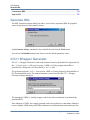
C/C++ Wrapper Generator. . . . . . . . . . . . . . . . . . . . . . . . . . . . . . . . . . . . . . . . . . . . . . . . . . .
ModelSim Compile . . . . . . . . . . . . . . . . . . . . . . . . . . . . . . . . . . . . . . . . . . . . . . . . . . . . . . . .
ModelSim Simulate . . . . . . . . . . . . . . . . . . . . . . . . . . . . . . . . . . . . . . . . . . . . . . . . . . . . . . . .
Using a ModelSim Simulator in Batch Mode. . . . . . . . . . . . . . . . . . . . . . . . . . . . . . . . . . .
Remote Simulation with SDF or PLI Files . . . . . . . . . . . . . . . . . . . . . . . . . . . . . . . . . . . . .
Synchronizing with an Externally Invoked Simulator . . . . . . . . . . . . . . . . . . . . . . . . . . . .
NC-Sim Compile . . . . . . . . . . . . . . . . . . . . . . . . . . . . . . . . . . . . . . . . . . . . . . . . . . . . . . . . . .
NC-Sim Simulate . . . . . . . . . . . . . . . . . . . . . . . . . . . . . . . . . . . . . . . . . . . . . . . . . . . . . . . . . .
Configuring NC-Sim for Remote Simulation . . . . . . . . . . . . . . . . . . . . . . . . . . . . . . . . . . .
QuestaSim Compile . . . . . . . . . . . . . . . . . . . . . . . . . . . . . . . . . . . . . . . . . . . . . . . . . . . . . . . .
Defining QuestaSim Compile Settings . . . . . . . . . . . . . . . . . . . . . . . . . . . . . . . . . . . . . . . .
QuestaSim Simulate. . . . . . . . . . . . . . . . . . . . . . . . . . . . . . . . . . . . . . . . . . . . . . . . . . . . . . . .
Defining QuestaSim Simulate Default Settings . . . . . . . . . . . . . . . . . . . . . . . . . . . . . . . . .
VCS or VCSi Compile. . . . . . . . . . . . . . . . . . . . . . . . . . . . . . . . . . . . . . . . . . . . . . . . . . . . . .
VCS/VCSi Simulate . . . . . . . . . . . . . . . . . . . . . . . . . . . . . . . . . . . . . . . . . . . . . . . . . . . . . . .
281
282
282
284
288
291
291
292
293
295
296
297
298
302
303
306
307
8
HDL Designer Series User Manual, V2008.1
September 18, 2008
Table of Contents
Configuring a Remote Server . . . . . . . . . . . . . . . . . . . . . . . . . . . . . . . . . . . . . . . . . . . . . . . .
Server Setup Commands. . . . . . . . . . . . . . . . . . . . . . . . . . . . . . . . . . . . . . . . . . . . . . . . . . .
Server Setup File Location . . . . . . . . . . . . . . . . . . . . . . . . . . . . . . . . . . . . . . . . . . . . . . . . .
LeonardoSpectrum. . . . . . . . . . . . . . . . . . . . . . . . . . . . . . . . . . . . . . . . . . . . . . . . . . . . . . . . .
LeonardoSpectrum Prepare Data . . . . . . . . . . . . . . . . . . . . . . . . . . . . . . . . . . . . . . . . . . . .
LeonardoSpectrum Synthesis Invoke . . . . . . . . . . . . . . . . . . . . . . . . . . . . . . . . . . . . . . . . .
The spectrum.tcl Script . . . . . . . . . . . . . . . . . . . . . . . . . . . . . . . . . . . . . . . . . . . . . . . . . . . .
LeonardoSpectrum Log Files . . . . . . . . . . . . . . . . . . . . . . . . . . . . . . . . . . . . . . . . . . . . . . .
Precision Synthesis . . . . . . . . . . . . . . . . . . . . . . . . . . . . . . . . . . . . . . . . . . . . . . . . . . . . . . . .
Precision Synthesis Prepare Data . . . . . . . . . . . . . . . . . . . . . . . . . . . . . . . . . . . . . . . . . . . .
Accessing the Precision Settings Dialog Box. . . . . . . . . . . . . . . . . . . . . . . . . . . . . . . . . . .
The General tab of the Precision Synthesis Settings dialog box. . . . . . . . . . . . . . . . . . .
The Setup tab of the Precision Synthesis Settings dialog box. . . . . . . . . . . . . . . . . . . . .
Precision Synthesis Invoke . . . . . . . . . . . . . . . . . . . . . . . . . . . . . . . . . . . . . . . . . . . . . . . . .
Precision Synthesis Run Scripts . . . . . . . . . . . . . . . . . . . . . . . . . . . . . . . . . . . . . . . . . . . . .
Design Compiler . . . . . . . . . . . . . . . . . . . . . . . . . . . . . . . . . . . . . . . . . . . . . . . . . . . . . . . . . .
Design Compiler Prepare Data . . . . . . . . . . . . . . . . . . . . . . . . . . . . . . . . . . . . . . . . . . . . . .
Design Compiler Invoke . . . . . . . . . . . . . . . . . . . . . . . . . . . . . . . . . . . . . . . . . . . . . . . . . . .
Synplify . . . . . . . . . . . . . . . . . . . . . . . . . . . . . . . . . . . . . . . . . . . . . . . . . . . . . . . . . . . . . . . . .
IO Designer . . . . . . . . . . . . . . . . . . . . . . . . . . . . . . . . . . . . . . . . . . . . . . . . . . . . . . . . . . . . . .
Invoking IO Designer . . . . . . . . . . . . . . . . . . . . . . . . . . . . . . . . . . . . . . . . . . . . . . . . . . . . .
Using IO Designer . . . . . . . . . . . . . . . . . . . . . . . . . . . . . . . . . . . . . . . . . . . . . . . . . . . . . . .
Synchronizing Results . . . . . . . . . . . . . . . . . . . . . . . . . . . . . . . . . . . . . . . . . . . . . . . . . . . .
. . . . . . . . . . . . . . . . . . . . . . . . . . . . . . . . . . . . . . . . . . . . . . . . . . . . . . . . Altera MegaWizard
Altera SOPC Builder . . . . . . . . . . . . . . . . . . . . . . . . . . . . . . . . . . . . . . . . . . . . . . . . . . . . . . .
Xilinx CORE Generator. . . . . . . . . . . . . . . . . . . . . . . . . . . . . . . . . . . . . . . . . . . . . . . . . . . . .
Xilinx Platform Studio. . . . . . . . . . . . . . . . . . . . . . . . . . . . . . . . . . . . . . . . . . . . . . . . . . . . . .
Xilinx Import . . . . . . . . . . . . . . . . . . . . . . . . . . . . . . . . . . . . . . . . . . . . . . . . . . . . . . . . . . . . .
Xilinx Import Settings dialog box . . . . . . . . . . . . . . . . . . . . . . . . . . . . . . . . . . . . . . . . . . .
Destination (Point) dialog box . . . . . . . . . . . . . . . . . . . . . . . . . . . . . . . . . . . . . . . . . . . . . .
Example: . . . . . . . . . . . . . . . . . . . . . . . . . . . . . . . . . . . . . . . . . . . . . . . . . . . . . . . . . . . . . . .
Prerequisites: . . . . . . . . . . . . . . . . . . . . . . . . . . . . . . . . . . . . . . . . . . . . . . . . . . . . . . . . . .
Steps: . . . . . . . . . . . . . . . . . . . . . . . . . . . . . . . . . . . . . . . . . . . . . . . . . . . . . . . . . . . . . . . .
FPGA Technology Setup . . . . . . . . . . . . . . . . . . . . . . . . . . . . . . . . . . . . . . . . . . . . . . . . . . . .
FPGA Vendor Library Compilation . . . . . . . . . . . . . . . . . . . . . . . . . . . . . . . . . . . . . . . . . .
Altera Quartus Synthesis Tools . . . . . . . . . . . . . . . . . . . . . . . . . . . . . . . . . . . . . . . . . . . . . . .
Quartus QIS Prepare Data. . . . . . . . . . . . . . . . . . . . . . . . . . . . . . . . . . . . . . . . . . . . . . . . . .
Quartus Place and Route. . . . . . . . . . . . . . . . . . . . . . . . . . . . . . . . . . . . . . . . . . . . . . . . . . .
Altera Quartus Programmer Tool . . . . . . . . . . . . . . . . . . . . . . . . . . . . . . . . . . . . . . . . . . . .
Xilinx Synthesis Tools. . . . . . . . . . . . . . . . . . . . . . . . . . . . . . . . . . . . . . . . . . . . . . . . . . . . . .
XST Prepare Data . . . . . . . . . . . . . . . . . . . . . . . . . . . . . . . . . . . . . . . . . . . . . . . . . . . . . . . .
Xilinx Place and Route . . . . . . . . . . . . . . . . . . . . . . . . . . . . . . . . . . . . . . . . . . . . . . . . . . . .
Xilinx FPGA Configuration . . . . . . . . . . . . . . . . . . . . . . . . . . . . . . . . . . . . . . . . . . . . . . . .
Actel Designer (R) . . . . . . . . . . . . . . . . . . . . . . . . . . . . . . . . . . . . . . . . . . . . . . . . . . . . . . . . .
Lattice ispLever . . . . . . . . . . . . . . . . . . . . . . . . . . . . . . . . . . . . . . . . . . . . . . . . . . . . . . . . . . .
SpyGlass . . . . . . . . . . . . . . . . . . . . . . . . . . . . . . . . . . . . . . . . . . . . . . . . . . . . . . . . . . . . . . . .
Concatenate HDL. . . . . . . . . . . . . . . . . . . . . . . . . . . . . . . . . . . . . . . . . . . . . . . . . . . . . . . . . .
Export RTL . . . . . . . . . . . . . . . . . . . . . . . . . . . . . . . . . . . . . . . . . . . . . . . . . . . . . . . . . . . . . .
HDL Designer Series User Manual, V2008.1
September 18, 2008
309
309
311
311
312
315
318
318
319
319
319
320
322
325
327
328
328
332
334
337
338
338
339
341
343
344
348
348
349
352
353
353
354
355
356
358
359
360
361
362
363
366
367
368
371
373
374
375
9
Table of Contents
Chapter 10
Setting Preferences . . . . . . . . . . . . . . . . . . . . . . . . . . . . . . . . . . . . . . . . . . . . . . . . . . . . . . . . .
Team and User Preferences . . . . . . . . . . . . . . . . . . . . . . . . . . . . . . . . . . . . . . . . . . . . . . . . . .
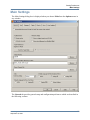
Main Settings . . . . . . . . . . . . . . . . . . . . . . . . . . . . . . . . . . . . . . . . . . . . . . . . . . . . . . . . . . . . .
File Naming . . . . . . . . . . . . . . . . . . . . . . . . . . . . . . . . . . . . . . . . . . . . . . . . . . . . . . . . . . . .
Toolbar Buttons . . . . . . . . . . . . . . . . . . . . . . . . . . . . . . . . . . . . . . . . . . . . . . . . . . . . . . . . .
User and Team Resource Files . . . . . . . . . . . . . . . . . . . . . . . . . . . . . . . . . . . . . . . . . . . . . .
Temporary Directory . . . . . . . . . . . . . . . . . . . . . . . . . . . . . . . . . . . . . . . . . . . . . . . . . . . . .
Remote Simulation Directory . . . . . . . . . . . . . . . . . . . . . . . . . . . . . . . . . . . . . . . . . . . . . . .
Units for Printing . . . . . . . . . . . . . . . . . . . . . . . . . . . . . . . . . . . . . . . . . . . . . . . . . . . . . . . .
Default Language . . . . . . . . . . . . . . . . . . . . . . . . . . . . . . . . . . . . . . . . . . . . . . . . . . . . . . . .
Text Editor and Printing Preferences . . . . . . . . . . . . . . . . . . . . . . . . . . . . . . . . . . . . . . . . .
Graphical Diagram Preferences . . . . . . . . . . . . . . . . . . . . . . . . . . . . . . . . . . . . . . . . . . . . .
Table Editor Preferences. . . . . . . . . . . . . . . . . . . . . . . . . . . . . . . . . . . . . . . . . . . . . . . . . . .
HDL Generation and Parser Checks . . . . . . . . . . . . . . . . . . . . . . . . . . . . . . . . . . . . . . . . . .
Strict Check Options. . . . . . . . . . . . . . . . . . . . . . . . . . . . . . . . . . . . . . . . . . . . . . . . . . . . .
Synthesis Checks . . . . . . . . . . . . . . . . . . . . . . . . . . . . . . . . . . . . . . . . . . . . . . . . . . . . . . .
Saving Diagrams. . . . . . . . . . . . . . . . . . . . . . . . . . . . . . . . . . . . . . . . . . . . . . . . . . . . . . . . .
Setting User Variables . . . . . . . . . . . . . . . . . . . . . . . . . . . . . . . . . . . . . . . . . . . . . . . . . . . .
Preferences for HDL Views. . . . . . . . . . . . . . . . . . . . . . . . . . . . . . . . . . . . . . . . . . . . . . . . . .
Setting HDL File Options . . . . . . . . . . . . . . . . . . . . . . . . . . . . . . . . . . . . . . . . . . . . . . . . . .
Verilog File Options . . . . . . . . . . . . . . . . . . . . . . . . . . . . . . . . . . . . . . . . . . . . . . . . . . . . .
VHDL File Options . . . . . . . . . . . . . . . . . . . . . . . . . . . . . . . . . . . . . . . . . . . . . . . . . . . . .
Setting Generated Filename Rules . . . . . . . . . . . . . . . . . . . . . . . . . . . . . . . . . . . . . . . . . .
Setting HDL Style Options . . . . . . . . . . . . . . . . . . . . . . . . . . . . . . . . . . . . . . . . . . . . . . . . .
Verilog Style Options . . . . . . . . . . . . . . . . . . . . . . . . . . . . . . . . . . . . . . . . . . . . . . . . . . . .
VHDL Style Options . . . . . . . . . . . . . . . . . . . . . . . . . . . . . . . . . . . . . . . . . . . . . . . . . . . .
HDL Translation Pragmas . . . . . . . . . . . . . . . . . . . . . . . . . . . . . . . . . . . . . . . . . . . . . . . .
VHDL Type Conversion . . . . . . . . . . . . . . . . . . . . . . . . . . . . . . . . . . . . . . . . . . . . . . . . .
Setting View Headers . . . . . . . . . . . . . . . . . . . . . . . . . . . . . . . . . . . . . . . . . . . . . . . . . . . . .
Setting Default Compiler Directives. . . . . . . . . . . . . . . . . . . . . . . . . . . . . . . . . . . . . . . . . .
Standard Compiler Directives . . . . . . . . . . . . . . . . . . . . . . . . . . . . . . . . . . . . . . . . . . . . .
Setting Default Package References . . . . . . . . . . . . . . . . . . . . . . . . . . . . . . . . . . . . . . . . . .
VHDL Standard Libraries . . . . . . . . . . . . . . . . . . . . . . . . . . . . . . . . . . . . . . . . . . . . . . . .
Standard VHDL Type Definitions . . . . . . . . . . . . . . . . . . . . . . . . . . . . . . . . . . . . . . . . . .
Defining VHDL Types . . . . . . . . . . . . . . . . . . . . . . . . . . . . . . . . . . . . . . . . . . . . . . . . . . .
Resolution Functions . . . . . . . . . . . . . . . . . . . . . . . . . . . . . . . . . . . . . . . . . . . . . . . . . . . .
Preferences for Graphical Views . . . . . . . . . . . . . . . . . . . . . . . . . . . . . . . . . . . . . . . . . . . . . .
Documentation and Visualization Preferences . . . . . . . . . . . . . . . . . . . . . . . . . . . . . . . . . .
HDL2Graphics Preferences . . . . . . . . . . . . . . . . . . . . . . . . . . . . . . . . . . . . . . . . . . . . . . . .
Diagram Master Preferences. . . . . . . . . . . . . . . . . . . . . . . . . . . . . . . . . . . . . . . . . . . . . . . .
Design Management Preferences. . . . . . . . . . . . . . . . . . . . . . . . . . . . . . . . . . . . . . . . . . . . . .
Version Management Preferences . . . . . . . . . . . . . . . . . . . . . . . . . . . . . . . . . . . . . . . . . . . . .
File Registration Preferences . . . . . . . . . . . . . . . . . . . . . . . . . . . . . . . . . . . . . . . . . . . . . . . . .
377
378
379
380
380
380
381
381
381
381
382
383
383
383
385
385
387
388
391
391
392
393
394
395
395
400
402
404
405
406
408
409
411
411
412
413
414
414
414
414
414
415
415
Chapter 11
Version Management . . . . . . . . . . . . . . . . . . . . . . . . . . . . . . . . . . . . . . . . . . . . . . . . . . . . . . . 417
Version Management Overview . . . . . . . . . . . . . . . . . . . . . . . . . . . . . . . . . . . . . . . . . . . . . . 418
10
HDL Designer Series User Manual, V2008.1
September 18, 2008
Table of Contents
Version Management Interface . . . . . . . . . . . . . . . . . . . . . . . . . . . . . . . . . . . . . . . . . . . . . . .
Version Management Status in the Design Explorer . . . . . . . . . . . . . . . . . . . . . . . . . . . . .
Setting Version Management Options . . . . . . . . . . . . . . . . . . . . . . . . . . . . . . . . . . . . . . . .
Choosing the Version Management tool . . . . . . . . . . . . . . . . . . . . . . . . . . . . . . . . . . . . .
Setting Repository Locations . . . . . . . . . . . . . . . . . . . . . . . . . . . . . . . . . . . . . . . . . . . . . .
Choosing Objects for Version Management Operations . . . . . . . . . . . . . . . . . . . . . . . . .
Other Version Management Options . . . . . . . . . . . . . . . . . . . . . . . . . . . . . . . . . . . . . . . .
The GNU Revision Control System (RCS) . . . . . . . . . . . . . . . . . . . . . . . . . . . . . . . . . . . .
Embedding Version Information . . . . . . . . . . . . . . . . . . . . . . . . . . . . . . . . . . . . . . . . . . .
The Concurrent Versions System (CVS) . . . . . . . . . . . . . . . . . . . . . . . . . . . . . . . . . . . . . .
Subversion (SVN). . . . . . . . . . . . . . . . . . . . . . . . . . . . . . . . . . . . . . . . . . . . . . . . . . . . . . . .
Enabling Subversion. . . . . . . . . . . . . . . . . . . . . . . . . . . . . . . . . . . . . . . . . . . . . . . . . . . . .
Rational ClearCase . . . . . . . . . . . . . . . . . . . . . . . . . . . . . . . . . . . . . . . . . . . . . . . . . . . . . . .
Synchronicity DesignSync . . . . . . . . . . . . . . . . . . . . . . . . . . . . . . . . . . . . . . . . . . . . . . . . .
Visual SourceSafe. . . . . . . . . . . . . . . . . . . . . . . . . . . . . . . . . . . . . . . . . . . . . . . . . . . . . . . .
ClioSoft SoS . . . . . . . . . . . . . . . . . . . . . . . . . . . . . . . . . . . . . . . . . . . . . . . . . . . . . . . . . . . .
Version Management Operations . . . . . . . . . . . . . . . . . . . . . . . . . . . . . . . . . . . . . . . . . . . . .
Version Management Toolbar . . . . . . . . . . . . . . . . . . . . . . . . . . . . . . . . . . . . . . . . . . . . . .
Setting the Scope for Version Management Commands . . . . . . . . . . . . . . . . . . . . . . . . . .
Select Hierarchy dialog box . . . . . . . . . . . . . . . . . . . . . . . . . . . . . . . . . . . . . . . . . . . . . . . .
Checking In / Committing Design Objects. . . . . . . . . . . . . . . . . . . . . . . . . . . . . . . . . . . . .
Check In / Commit dialog box . . . . . . . . . . . . . . . . . . . . . . . . . . . . . . . . . . . . . . . . . . . . .
How Subversion handles committing the same version of a text file by 2 different users.
Prerequisites: . . . . . . . . . . . . . . . . . . . . . . . . . . . . . . . . . . . . . . . . . . . . . . . . . . . . . . . . . .
Steps: . . . . . . . . . . . . . . . . . . . . . . . . . . . . . . . . . . . . . . . . . . . . . . . . . . . . . . . . . . . . . . . .
Example for Modifying a design unit using Subversion . . . . . . . . . . . . . . . . . . . . . . . . . .
Prerequisites: . . . . . . . . . . . . . . . . . . . . . . . . . . . . . . . . . . . . . . . . . . . . . . . . . . . . . . . . . .
Steps: . . . . . . . . . . . . . . . . . . . . . . . . . . . . . . . . . . . . . . . . . . . . . . . . . . . . . . . . . . . . . . . .
Checking Out Design Objects. . . . . . . . . . . . . . . . . . . . . . . . . . . . . . . . . . . . . . . . . . . . . . .
Check Out dialog box. . . . . . . . . . . . . . . . . . . . . . . . . . . . . . . . . . . . . . . . . . . . . . . . . . . .
Checking Out Subversion Design Objects . . . . . . . . . . . . . . . . . . . . . . . . . . . . . . . . . . . .
Getting Design Objects . . . . . . . . . . . . . . . . . . . . . . . . . . . . . . . . . . . . . . . . . . . . . . . . . . . .
Get dialog box . . . . . . . . . . . . . . . . . . . . . . . . . . . . . . . . . . . . . . . . . . . . . . . . . . . . . . . . .
Undoing a Check Out / Reverting. . . . . . . . . . . . . . . . . . . . . . . . . . . . . . . . . . . . . . . . . . . .
Undo a Check Out / Revert dialog box . . . . . . . . . . . . . . . . . . . . . . . . . . . . . . . . . . . . . .
Locking and Unlocking Views . . . . . . . . . . . . . . . . . . . . . . . . . . . . . . . . . . . . . . . . . . . . . .
Change Lock dialog box. . . . . . . . . . . . . . . . . . . . . . . . . . . . . . . . . . . . . . . . . . . . . . . . . .
Locking Subversion Views . . . . . . . . . . . . . . . . . . . . . . . . . . . . . . . . . . . . . . . . . . . . . . . . .
Lock dialog box . . . . . . . . . . . . . . . . . . . . . . . . . . . . . . . . . . . . . . . . . . . . . . . . . . . . . . . .
Unlocking Subversion Views . . . . . . . . . . . . . . . . . . . . . . . . . . . . . . . . . . . . . . . . . . . . . . .
Unlock dialog box . . . . . . . . . . . . . . . . . . . . . . . . . . . . . . . . . . . . . . . . . . . . . . . . . . . . . .
Adding a Label . . . . . . . . . . . . . . . . . . . . . . . . . . . . . . . . . . . . . . . . . . . . . . . . . . . . . . . . . .
Label dialog box . . . . . . . . . . . . . . . . . . . . . . . . . . . . . . . . . . . . . . . . . . . . . . . . . . . . . . . .
Synchronizing / Updating the Workspace . . . . . . . . . . . . . . . . . . . . . . . . . . . . . . . . . . . . .
Synchronize / Update dialog box . . . . . . . . . . . . . . . . . . . . . . . . . . . . . . . . . . . . . . . . . . .
Reporting Version Management Status . . . . . . . . . . . . . . . . . . . . . . . . . . . . . . . . . . . . . . .
Status dialog box . . . . . . . . . . . . . . . . . . . . . . . . . . . . . . . . . . . . . . . . . . . . . . . . . . . . . . .
Reporting Version Management History . . . . . . . . . . . . . . . . . . . . . . . . . . . . . . . . . . . . . .
History dialog box . . . . . . . . . . . . . . . . . . . . . . . . . . . . . . . . . . . . . . . . . . . . . . . . . . . . . .
HDL Designer Series User Manual, V2008.1
September 18, 2008
419
419
422
424
425
426
426
427
429
429
432
434
434
436
437
439
440
440
441
442
443
444
446
446
446
448
448
449
451
452
453
454
455
456
457
458
459
461
461
462
463
464
465
467
468
470
470
471
472
11
Table of Contents
Comparing Text Files . . . . . . . . . . . . . . . . . . . . . . . . . . . . . . . . . . . . . . . . . . . . . . . . . . . . .
Compare dialog box . . . . . . . . . . . . . . . . . . . . . . . . . . . . . . . . . . . . . . . . . . . . . . . . . . . . .
Compare Files dialog box. . . . . . . . . . . . . . . . . . . . . . . . . . . . . . . . . . . . . . . . . . . . . . . . .
Creating a Branch . . . . . . . . . . . . . . . . . . . . . . . . . . . . . . . . . . . . . . . . . . . . . . . . . . . . . . . .
Create a Branch dialog box . . . . . . . . . . . . . . . . . . . . . . . . . . . . . . . . . . . . . . . . . . . . . . .
Deleting Objects from the Repository . . . . . . . . . . . . . . . . . . . . . . . . . . . . . . . . . . . . . . . .
Delete Files from Repository dialog box . . . . . . . . . . . . . . . . . . . . . . . . . . . . . . . . . . . . .
Version Management Using a Command File. . . . . . . . . . . . . . . . . . . . . . . . . . . . . . . . . . . .
Version Management Tasks Supported for different tools . . . . . . . . . . . . . . . . . . . . . . . . . .
474
475
476
478
478
480
480
481
482
Appendix A
Naming Conventions. . . . . . . . . . . . . . . . . . . . . . . . . . . . . . . . . . . . . . . . . . . . . . . . . . . . . . . .
File Naming . . . . . . . . . . . . . . . . . . . . . . . . . . . . . . . . . . . . . . . . . . . . . . . . . . . . . . . . . . . . . .
Identifiers and Reserved Words. . . . . . . . . . . . . . . . . . . . . . . . . . . . . . . . . . . . . . . . . . . . . . .
Verilog Identifiers. . . . . . . . . . . . . . . . . . . . . . . . . . . . . . . . . . . . . . . . . . . . . . . . . . . . . . . .
Standard Verilog Types . . . . . . . . . . . . . . . . . . . . . . . . . . . . . . . . . . . . . . . . . . . . . . . . . . .
Verilog Reserved Words. . . . . . . . . . . . . . . . . . . . . . . . . . . . . . . . . . . . . . . . . . . . . . . . . . .
VHDL Identifiers . . . . . . . . . . . . . . . . . . . . . . . . . . . . . . . . . . . . . . . . . . . . . . . . . . . . . . . .
VHDL Reserved Words . . . . . . . . . . . . . . . . . . . . . . . . . . . . . . . . . . . . . . . . . . . . . . . . . . .
Additional Reserved Words in a State Machine . . . . . . . . . . . . . . . . . . . . . . . . . . . . . . . . .
Case Sensitivity. . . . . . . . . . . . . . . . . . . . . . . . . . . . . . . . . . . . . . . . . . . . . . . . . . . . . . . . . .
485
485
486
486
486
486
487
488
488
489
Appendix B
Resource Files . . . . . . . . . . . . . . . . . . . . . . . . . . . . . . . . . . . . . . . . . . . . . . . . . . . . . . . . . . . . .
File Structure . . . . . . . . . . . . . . . . . . . . . . . . . . . . . . . . . . . . . . . . . . . . . . . . . . . . . . . . . . . . .
Team and User Home Locations . . . . . . . . . . . . . . . . . . . . . . . . . . . . . . . . . . . . . . . . . . . . . .
Reading Resource Files . . . . . . . . . . . . . . . . . . . . . . . . . . . . . . . . . . . . . . . . . . . . . . . . . . . . .
Writing Resource Files . . . . . . . . . . . . . . . . . . . . . . . . . . . . . . . . . . . . . . . . . . . . . . . . . . . . .
491
491
493
494
494
Appendix C
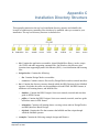
Installation Directory Structure . . . . . . . . . . . . . . . . . . . . . . . . . . . . . . . . . . . . . . . . . . . . . . 495
Appendix D
Text Editors . . . . . . . . . . . . . . . . . . . . . . . . . . . . . . . . . . . . . . . . . . . . . . . . . . . . . . . . . . . . . . .
HDL Text Entry . . . . . . . . . . . . . . . . . . . . . . . . . . . . . . . . . . . . . . . . . . . . . . . . . . . . . . . . . . .
Setting the Text Editor . . . . . . . . . . . . . . . . . . . . . . . . . . . . . . . . . . . . . . . . . . . . . . . . . . . . . .
Using the NEdit Editor . . . . . . . . . . . . . . . . . . . . . . . . . . . . . . . . . . . . . . . . . . . . . . . . . . . .
Using the Emacs Editor . . . . . . . . . . . . . . . . . . . . . . . . . . . . . . . . . . . . . . . . . . . . . . . . . . .
Example Load Script for Emacs and XEmacs . . . . . . . . . . . . . . . . . . . . . . . . . . . . . . . . .
Using the TextPad Editor . . . . . . . . . . . . . . . . . . . . . . . . . . . . . . . . . . . . . . . . . . . . . . . . . .
Using the Notepad Editor . . . . . . . . . . . . . . . . . . . . . . . . . . . . . . . . . . . . . . . . . . . . . . . . . .
Using the WordPad Editor . . . . . . . . . . . . . . . . . . . . . . . . . . . . . . . . . . . . . . . . . . . . . . . . .
Using the UltraEdit Editor . . . . . . . . . . . . . . . . . . . . . . . . . . . . . . . . . . . . . . . . . . . . . . . . .
Using the WinEdit Editor . . . . . . . . . . . . . . . . . . . . . . . . . . . . . . . . . . . . . . . . . . . . . . . . . .
Using the HDL Turbo Writer Editor. . . . . . . . . . . . . . . . . . . . . . . . . . . . . . . . . . . . . . . . . .
Using the XEmacs Editor . . . . . . . . . . . . . . . . . . . . . . . . . . . . . . . . . . . . . . . . . . . . . . . . . .
Using the Default UNIX Editor . . . . . . . . . . . . . . . . . . . . . . . . . . . . . . . . . . . . . . . . . . . . .
12
499
499
500
501
503
504
506
507
508
508
508
509
510
511
HDL Designer Series User Manual, V2008.1
September 18, 2008
Table of Contents
Appendix E
Defining Key Shortcuts. . . . . . . . . . . . . . . . . . . . . . . . . . . . . . . . . . . . . . . . . . . . . . . . . . . . . . 513
List of Key Codes . . . . . . . . . . . . . . . . . . . . . . . . . . . . . . . . . . . . . . . . . . . . . . . . . . . . . . . . . 515
Internal Functions . . . . . . . . . . . . . . . . . . . . . . . . . . . . . . . . . . . . . . . . . . . . . . . . . . . . . . . . . 516
Appendix F
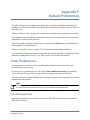
Default Preferences. . . . . . . . . . . . . . . . . . . . . . . . . . . . . . . . . . . . . . . . . . . . . . . . . . . . . . . . .
Team Preferences. . . . . . . . . . . . . . . . . . . . . . . . . . . . . . . . . . . . . . . . . . . . . . . . . . . . . . . . . .
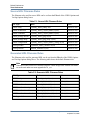
File Naming Rules . . . . . . . . . . . . . . . . . . . . . . . . . . . . . . . . . . . . . . . . . . . . . . . . . . . . . . .
Source HDL Filename Rules . . . . . . . . . . . . . . . . . . . . . . . . . . . . . . . . . . . . . . . . . . . . . .
Generated HDL Filename Rules . . . . . . . . . . . . . . . . . . . . . . . . . . . . . . . . . . . . . . . . . . .
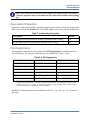
Generation Properties . . . . . . . . . . . . . . . . . . . . . . . . . . . . . . . . . . . . . . . . . . . . . . . . . . . . .
File Registration . . . . . . . . . . . . . . . . . . . . . . . . . . . . . . . . . . . . . . . . . . . . . . . . . . . . . . . . .
Version Management Options . . . . . . . . . . . . . . . . . . . . . . . . . . . . . . . . . . . . . . . . . . . . . .
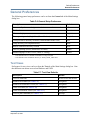
User Preferences . . . . . . . . . . . . . . . . . . . . . . . . . . . . . . . . . . . . . . . . . . . . . . . . . . . . . . . . . .
General Preferences . . . . . . . . . . . . . . . . . . . . . . . . . . . . . . . . . . . . . . . . . . . . . . . . . . . . . . . .
Text Views . . . . . . . . . . . . . . . . . . . . . . . . . . . . . . . . . . . . . . . . . . . . . . . . . . . . . . . . . . . . .
HDL Text Editor and Viewer . . . . . . . . . . . . . . . . . . . . . . . . . . . . . . . . . . . . . . . . . . . . . .
Text View Printing . . . . . . . . . . . . . . . . . . . . . . . . . . . . . . . . . . . . . . . . . . . . . . . . . . . . . .
Diagram Views . . . . . . . . . . . . . . . . . . . . . . . . . . . . . . . . . . . . . . . . . . . . . . . . . . . . . . . . . .
Table Views . . . . . . . . . . . . . . . . . . . . . . . . . . . . . . . . . . . . . . . . . . . . . . . . . . . . . . . . . . . .
HDL Generation and Parser Checks . . . . . . . . . . . . . . . . . . . . . . . . . . . . . . . . . . . . . . . . . .
Saving Graphic Editor Views . . . . . . . . . . . . . . . . . . . . . . . . . . . . . . . . . . . . . . . . . . . . . . .
VHDL File Options. . . . . . . . . . . . . . . . . . . . . . . . . . . . . . . . . . . . . . . . . . . . . . . . . . . . . . .
VHDL Style Options. . . . . . . . . . . . . . . . . . . . . . . . . . . . . . . . . . . . . . . . . . . . . . . . . . . . . .
Embedded VHDL Configuration Options . . . . . . . . . . . . . . . . . . . . . . . . . . . . . . . . . . . .
Standalone VHDL Configuration Options . . . . . . . . . . . . . . . . . . . . . . . . . . . . . . . . . . . .
VHDL Headers . . . . . . . . . . . . . . . . . . . . . . . . . . . . . . . . . . . . . . . . . . . . . . . . . . . . . . . . . .
VHDL Graphical View Headers . . . . . . . . . . . . . . . . . . . . . . . . . . . . . . . . . . . . . . . . . . .
VHDL Header for a Generated Entity View . . . . . . . . . . . . . . . . . . . . . . . . . . . . . . . . . .
VHDL Embedded Constraints . . . . . . . . . . . . . . . . . . . . . . . . . . . . . . . . . . . . . . . . . . . . .
VHDL Test Bench Headers . . . . . . . . . . . . . . . . . . . . . . . . . . . . . . . . . . . . . . . . . . . . . . . .
VHDL Package References . . . . . . . . . . . . . . . . . . . . . . . . . . . . . . . . . . . . . . . . . . . . . . . .
Verilog File Options . . . . . . . . . . . . . . . . . . . . . . . . . . . . . . . . . . . . . . . . . . . . . . . . . . . . . .
Verilog Style Options . . . . . . . . . . . . . . . . . . . . . . . . . . . . . . . . . . . . . . . . . . . . . . . . . . . . .
Verilog Headers . . . . . . . . . . . . . . . . . . . . . . . . . . . . . . . . . . . . . . . . . . . . . . . . . . . . . . . . .
Verilog Graphical View Headers . . . . . . . . . . . . . . . . . . . . . . . . . . . . . . . . . . . . . . . . . . .
Verilog Embedded Constraints. . . . . . . . . . . . . . . . . . . . . . . . . . . . . . . . . . . . . . . . . . . . .
Verilog Test Bench Header. . . . . . . . . . . . . . . . . . . . . . . . . . . . . . . . . . . . . . . . . . . . . . . . .
Verilog Compiler Directives. . . . . . . . . . . . . . . . . . . . . . . . . . . . . . . . . . . . . . . . . . . . . . . .
Design Management Options . . . . . . . . . . . . . . . . . . . . . . . . . . . . . . . . . . . . . . . . . . . . . . .
Graphical Rendering Preferences . . . . . . . . . . . . . . . . . . . . . . . . . . . . . . . . . . . . . . . . . . . .
HTML Export Setup . . . . . . . . . . . . . . . . . . . . . . . . . . . . . . . . . . . . . . . . . . . . . . . . . . . . . .
Visualization Setup . . . . . . . . . . . . . . . . . . . . . . . . . . . . . . . . . . . . . . . . . . . . . . . . . . . . . . .
Hierarchy Options. . . . . . . . . . . . . . . . . . . . . . . . . . . . . . . . . . . . . . . . . . . . . . . . . . . . . . . .
Page Setup Preferences . . . . . . . . . . . . . . . . . . . . . . . . . . . . . . . . . . . . . . . . . . . . . . . . . . . .
Diagram Preferences. . . . . . . . . . . . . . . . . . . . . . . . . . . . . . . . . . . . . . . . . . . . . . . . . . . . . .
Block Diagram Preferences . . . . . . . . . . . . . . . . . . . . . . . . . . . . . . . . . . . . . . . . . . . . . . .
HDL Designer Series User Manual, V2008.1
September 18, 2008
519
519
519
520
520
521
521
522
522
523
523
524
525
525
526
526
527
527
528
529
529
530
530
531
531
531
532
532
533
534
534
535
535
535
536
537
538
539
540
540
541
542
13
Table of Contents
Interface Preferences . . . . . . . . . . . . . . . . . . . . . . . . . . . . . . . . . . . . . . . . . . . . . . . . . . . .
Truth Table Preferences . . . . . . . . . . . . . . . . . . . . . . . . . . . . . . . . . . . . . . . . . . . . . . . . . .
State Machine Preferences . . . . . . . . . . . . . . . . . . . . . . . . . . . . . . . . . . . . . . . . . . . . . . . .
ASM Chart Preferences . . . . . . . . . . . . . . . . . . . . . . . . . . . . . . . . . . . . . . . . . . . . . . . . . .
Flow Chart Preferences . . . . . . . . . . . . . . . . . . . . . . . . . . . . . . . . . . . . . . . . . . . . . . . . . .
Animation Preferences . . . . . . . . . . . . . . . . . . . . . . . . . . . . . . . . . . . . . . . . . . . . . . . . . . .
Simulation Probe Properties . . . . . . . . . . . . . . . . . . . . . . . . . . . . . . . . . . . . . . . . . . . . . . .
Toolbar Settings . . . . . . . . . . . . . . . . . . . . . . . . . . . . . . . . . . . . . . . . . . . . . . . . . . . . . . . .
Miscellaneous Preferences . . . . . . . . . . . . . . . . . . . . . . . . . . . . . . . . . . . . . . . . . . . . . . . . .
Visual Attributes . . . . . . . . . . . . . . . . . . . . . . . . . . . . . . . . . . . . . . . . . . . . . . . . . . . . . . . . .
544
545
546
548
549
549
550
550
550
551
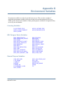
Appendix G
Environment Variables . . . . . . . . . . . . . . . . . . . . . . . . . . . . . . . . . . . . . . . . . . . . . . . . . . . . .
List of Variables. . . . . . . . . . . . . . . . . . . . . . . . . . . . . . . . . . . . . . . . . . . . . . . . . . . . . . . . . . .
Using Environment Variables . . . . . . . . . . . . . . . . . . . . . . . . . . . . . . . . . . . . . . . . . . . . . . . .
Setting Environment Variables . . . . . . . . . . . . . . . . . . . . . . . . . . . . . . . . . . . . . . . . . . . . . . .
553
554
559
560
Glossary
Index 585
Index
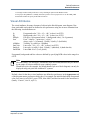
Third-Party Information
End-User License Agreement
14
HDL Designer Series User Manual, V2008.1
September 18, 2008
Table of Contents
HDL Designer Series User Manual, V2008.1
September 18, 2008
15
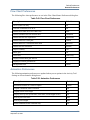
List of Tables
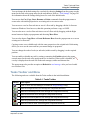
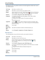
Table 1-1. LaunchPad Icons . . . . . . . . . . . . . . . . . . . . . . . . . . . . . . . . . . . . . . . . . . . . . . . . .
Table 1-2. Standard Toolbar . . . . . . . . . . . . . . . . . . . . . . . . . . . . . . . . . . . . . . . . . . . . . . . . .
Table 1-3. Design Manager Toolbar . . . . . . . . . . . . . . . . . . . . . . . . . . . . . . . . . . . . . . . . . . .
Table 1-4. HDL Tools Toolbar . . . . . . . . . . . . . . . . . . . . . . . . . . . . . . . . . . . . . . . . . . . . . . .
Table 1-5. Tasks Toolbar . . . . . . . . . . . . . . . . . . . . . . . . . . . . . . . . . . . . . . . . . . . . . . . . . . .
Table 1-6. Project Shortcut Bar . . . . . . . . . . . . . . . . . . . . . . . . . . . . . . . . . . . . . . . . . . . . . .
Table 1-7. Main Shortcut Bar . . . . . . . . . . . . . . . . . . . . . . . . . . . . . . . . . . . . . . . . . . . . . . . .
Table 1-8. Explore Shortcut Bar . . . . . . . . . . . . . . . . . . . . . . . . . . . . . . . . . . . . . . . . . . . . . .
Table 1-9. Tasks Shortcut Bar . . . . . . . . . . . . . . . . . . . . . . . . . . . . . . . . . . . . . . . . . . . . . . .
Table 1-10. Viewpoints Shortcut Bar . . . . . . . . . . . . . . . . . . . . . . . . . . . . . . . . . . . . . . . . . .
Table 1-11. Log Window Toolbar . . . . . . . . . . . . . . . . . . . . . . . . . . . . . . . . . . . . . . . . . . . .
Table 1-12. Console Tab Color Conventions . . . . . . . . . . . . . . . . . . . . . . . . . . . . . . . . . . . .
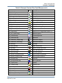
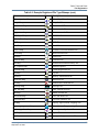
Table 2-1. Project Manager Notation . . . . . . . . . . . . . . . . . . . . . . . . . . . . . . . . . . . . . . . . . .
Table 2-2. Library Creation Details . . . . . . . . . . . . . . . . . . . . . . . . . . . . . . . . . . . . . . . . . . .
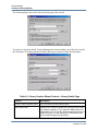
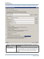
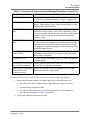
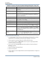
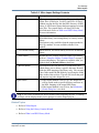
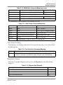
Table 2-3. Library Creation Wizard Controls - Library Details Page . . . . . . . . . . . . . . . . .
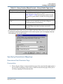
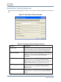
Table 2-4. Library Creation Wizard Controls - Downstream Data Directories Page . . . . . .
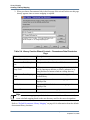
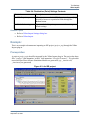
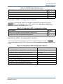
Table 2-5. Library Creation Wizard Controls - Library Options Page . . . . . . . . . . . . . . . . .
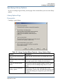
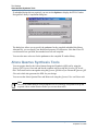
Table 2-6. Library Creation Wizard Controls - Version Management Page . . . . . . . . . . . .
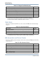
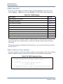
Table 2-7. Default Downstream Library Mapping . . . . . . . . . . . . . . . . . . . . . . . . . . . . . . . .
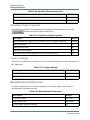
Table 3-1. Viewpoint Management Window . . . . . . . . . . . . . . . . . . . . . . . . . . . . . . . . . . . .
Table 3-2. Predefined Viewpoints . . . . . . . . . . . . . . . . . . . . . . . . . . . . . . . . . . . . . . . . . . . .
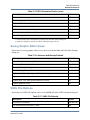
Table 3-3. Controls of Delete Special Options Dialog Box . . . . . . . . . . . . . . . . . . . . . . . . .
Table 3-4. Controls of Delete from Disk Dialog Box . . . . . . . . . . . . . . . . . . . . . . . . . . . . . .
Table 3-5. Design Explorer Notation . . . . . . . . . . . . . . . . . . . . . . . . . . . . . . . . . . . . . . . . . .
Table 3-6. Registered File Types Icons . . . . . . . . . . . . . . . . . . . . . . . . . . . . . . . . . . . . . . . .
Table 3-7. Marker Icons . . . . . . . . . . . . . . . . . . . . . . . . . . . . . . . . . . . . . . . . . . . . . . . . . . . .
Table 3-8. Side Data Browser Notation . . . . . . . . . . . . . . . . . . . . . . . . . . . . . . . . . . . . . . . .
Table 3-9. Downstream Browser Notation . . . . . . . . . . . . . . . . . . . . . . . . . . . . . . . . . . . . . .
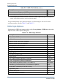
Table 5-1. Library Mappings . . . . . . . . . . . . . . . . . . . . . . . . . . . . . . . . . . . . . . . . . . . . . . . .
Table 5-2. Controls of Add Existing Design Wizard - Main Page . . . . . . . . . . . . . . . . . . . .
Table 5-3. Controls of Add Existing Design Wizard - Summary Page . . . . . . . . . . . . . . . .
Table 5-4. Controls of Add Existing Files Dialog Box . . . . . . . . . . . . . . . . . . . . . . . . . . . .
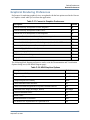
Table 7-1. Navigation Frame Toolbar . . . . . . . . . . . . . . . . . . . . . . . . . . . . . . . . . . . . . . . . .
Table 7-2. JPEG and PNG Design Frame Toolbar . . . . . . . . . . . . . . . . . . . . . . . . . . . . . . . .
Table 7-3. SVG Design Frame Toolbar . . . . . . . . . . . . . . . . . . . . . . . . . . . . . . . . . . . . . . . .
Table 8-1. Tasks Toolbar . . . . . . . . . . . . . . . . . . . . . . . . . . . . . . . . . . . . . . . . . . . . . . . . . . .
Table 8-2. Example Tool and Flow Task Bitmaps . . . . . . . . . . . . . . . . . . . . . . . . . . . . . . . .
Table 8-3. Example Registered File Type Bitmaps . . . . . . . . . . . . . . . . . . . . . . . . . . . . . . .
Table 8-4. Default Flow Tasks in Task Manager . . . . . . . . . . . . . . . . . . . . . . . . . . . . . . . . .
Table 8-5. Additional Flow Tasks . . . . . . . . . . . . . . . . . . . . . . . . . . . . . . . . . . . . . . . . . . . .
HDL Designer Series User Manual, V2008.1
September 18, 2008
22
25
26
26
27
29
29
30
30
31
36
38
48
60
62
64
65
67
69
86
86
111
113
125
127
127
131
133
166
170
172
184
223
223
226
265
266
274
279
279
16
List of Tables
Table 9-1. Controls of Precision Synthesis Settings Dialog Box - General Tab . . . . . . . . .
Table 9-2. Controls of Precision Synthesis Settings Dialog Box - Setup Tab . . . . . . . . . . .
Table 9-3. Xilinx Import Settings Contents . . . . . . . . . . . . . . . . . . . . . . . . . . . . . . . . . . . . .
Table 9-4. Destination (Point) Settings Contents . . . . . . . . . . . . . . . . . . . . . . . . . . . . . . . . .
Table 10-1. Verilog 2005 Generation Options . . . . . . . . . . . . . . . . . . . . . . . . . . . . . . . . . . .
Table 10-2. Examples of code generated using the listed module port option . . . . . . . . . . .
Table 11-1. Version Management Settings Dialog box — Panes . . . . . . . . . . . . . . . . . . . .
Table 11-2. Version Management Settings Contents . . . . . . . . . . . . . . . . . . . . . . . . . . . . .
Table 11-3. Version Management Settings Contents . . . . . . . . . . . . . . . . . . . . . . . . . . . . .
Table 11-4. Version Management Settings Contents . . . . . . . . . . . . . . . . . . . . . . . . . . . . .
Table 11-5. Version Management Settings Contents . . . . . . . . . . . . . . . . . . . . . . . . . . . . .
Table 11-6. Version Management Toolbar . . . . . . . . . . . . . . . . . . . . . . . . . . . . . . . . . . . . . .
Table 11-7. Select Hierarchy Contents . . . . . . . . . . . . . . . . . . . . . . . . . . . . . . . . . . . . . . . . .
Table 11-8. Check In / Commit Contents . . . . . . . . . . . . . . . . . . . . . . . . . . . . . . . . . . . . . . .
Table 11-9. Design Units — Types . . . . . . . . . . . . . . . . . . . . . . . . . . . . . . . . . . . . . . . . . . .
Table 11-10. Check Out Contents . . . . . . . . . . . . . . . . . . . . . . . . . . . . . . . . . . . . . . . . . . . . .
Table 11-11. Check Out Contents . . . . . . . . . . . . . . . . . . . . . . . . . . . . . . . . . . . . . . . . . . . . .
Table 11-12. Get Contents . . . . . . . . . . . . . . . . . . . . . . . . . . . . . . . . . . . . . . . . . . . . . . . . . .
Table 11-13. Undo Check Out / Revert Contents . . . . . . . . . . . . . . . . . . . . . . . . . . . . . . . . .
Table 11-14. Change Lock Contents . . . . . . . . . . . . . . . . . . . . . . . . . . . . . . . . . . . . . . . . . .
Table 11-15. Lock Contents . . . . . . . . . . . . . . . . . . . . . . . . . . . . . . . . . . . . . . . . . . . . . . . . .
Table 11-16. Unlock Contents . . . . . . . . . . . . . . . . . . . . . . . . . . . . . . . . . . . . . . . . . . . . . . .
Table 11-17. Label Contents . . . . . . . . . . . . . . . . . . . . . . . . . . . . . . . . . . . . . . . . . . . . . . . . .
Table 11-18. Synchronize / Update Contents . . . . . . . . . . . . . . . . . . . . . . . . . . . . . . . . . . . .
Table 11-19. Status Contents . . . . . . . . . . . . . . . . . . . . . . . . . . . . . . . . . . . . . . . . . . . . . . . .
Table 11-20. History Contents . . . . . . . . . . . . . . . . . . . . . . . . . . . . . . . . . . . . . . . . . . . . . . .
Table 11-21. Compare Contents . . . . . . . . . . . . . . . . . . . . . . . . . . . . . . . . . . . . . . . . . . . . . .
Table 11-22. Compare files Contents . . . . . . . . . . . . . . . . . . . . . . . . . . . . . . . . . . . . . . . . . .
Table 11-23. Create a Branch Contents . . . . . . . . . . . . . . . . . . . . . . . . . . . . . . . . . . . . . . . .
Table 11-24. Delete Files from Repository Contents . . . . . . . . . . . . . . . . . . . . . . . . . . . . . .
Table 11-25. Table of Tools . . . . . . . . . . . . . . . . . . . . . . . . . . . . . . . . . . . . . . . . . . . . . . . . .
Table E-1. Alphabetic Keys . . . . . . . . . . . . . . . . . . . . . . . . . . . . . . . . . . . . . . . . . . . . . . . . .
Table E-2. Function Keys . . . . . . . . . . . . . . . . . . . . . . . . . . . . . . . . . . . . . . . . . . . . . . . . . . .
Table E-3. Special Purpose Keys . . . . . . . . . . . . . . . . . . . . . . . . . . . . . . . . . . . . . . . . . . . . .
Table F-1. Source HDL Filename Rules . . . . . . . . . . . . . . . . . . . . . . . . . . . . . . . . . . . . . . . .
Table F-2. Generated HDL Filename Rules . . . . . . . . . . . . . . . . . . . . . . . . . . . . . . . . . . . . .
Table F-3. Generation Properties . . . . . . . . . . . . . . . . . . . . . . . . . . . . . . . . . . . . . . . . . . . . .
Table F-4. File Registration . . . . . . . . . . . . . . . . . . . . . . . . . . . . . . . . . . . . . . . . . . . . . . . . .
Table F-5. Version Management Options . . . . . . . . . . . . . . . . . . . . . . . . . . . . . . . . . . . . . . .
Table F-6. General Setup Preferences . . . . . . . . . . . . . . . . . . . . . . . . . . . . . . . . . . . . . . . . .
Table F-7. Text View Defaults . . . . . . . . . . . . . . . . . . . . . . . . . . . . . . . . . . . . . . . . . . . . . . .
Table F-8. Windows Editor Command Mappings . . . . . . . . . . . . . . . . . . . . . . . . . . . . . . . .
Table F-9. Windows Viewer Command Mappings . . . . . . . . . . . . . . . . . . . . . . . . . . . . . . .
Table F-10. UNIX Editor Command Mappings . . . . . . . . . . . . . . . . . . . . . . . . . . . . . . . . . .
Table F-11. UNIX Viewer Command Mappings . . . . . . . . . . . . . . . . . . . . . . . . . . . . . . . . .
HDL Designer Series User Manual, V2008.1
September 18, 2008
320
323
350
352
397
399
424
424
425
426
426
440
442
445
449
452
453
455
458
460
462
464
466
469
471
473
476
477
479
481
482
515
515
516
520
520
521
521
522
523
523
524
524
524
525
17
List of Tables
Table F-12. Text View Print Command Mapping . . . . . . . . . . . . . . . . . . . . . . . . . . . . . . . .
Table F-13. Diagram View Defaults . . . . . . . . . . . . . . . . . . . . . . . . . . . . . . . . . . . . . . . . . . .
Table F-14. Table View Defaults . . . . . . . . . . . . . . . . . . . . . . . . . . . . . . . . . . . . . . . . . . . . .
Table F-15. HDL Generation Checks . . . . . . . . . . . . . . . . . . . . . . . . . . . . . . . . . . . . . . . . . .
Table F-16. Autosave and Backup Defaults . . . . . . . . . . . . . . . . . . . . . . . . . . . . . . . . . . . . .
Table F-17. VHDL File Defaults . . . . . . . . . . . . . . . . . . . . . . . . . . . . . . . . . . . . . . . . . . . . .
Table F-18. VHDL Style Defaults . . . . . . . . . . . . . . . . . . . . . . . . . . . . . . . . . . . . . . . . . . . .
Table F-19. Embedded VHDL Configuration Options . . . . . . . . . . . . . . . . . . . . . . . . . . . . .
Table F-20. Standalone VHDL Configuration Options . . . . . . . . . . . . . . . . . . . . . . . . . . . .
Table F-21. VHDL Headers . . . . . . . . . . . . . . . . . . . . . . . . . . . . . . . . . . . . . . . . . . . . . . . . .
Table F-22. VHDL Graphical Views . . . . . . . . . . . . . . . . . . . . . . . . . . . . . . . . . . . . . . . . . .
Table F-23. Symbol . . . . . . . . . . . . . . . . . . . . . . . . . . . . . . . . . . . . . . . . . . . . . . . . . . . . . . .
Table F-24. VHDL Embedded Constraints . . . . . . . . . . . . . . . . . . . . . . . . . . . . . . . . . . . . .
Table F-25. VHDL Test Bench Architecture . . . . . . . . . . . . . . . . . . . . . . . . . . . . . . . . . . . .
Table F-28. VHDL Package References . . . . . . . . . . . . . . . . . . . . . . . . . . . . . . . . . . . . . . . .
Table F-29. Verilog File Defaults . . . . . . . . . . . . . . . . . . . . . . . . . . . . . . . . . . . . . . . . . . . . .
Table F-26. VHDL Test Bench Entity . . . . . . . . . . . . . . . . . . . . . . . . . . . . . . . . . . . . . . . . .
Table F-27. VHDL Test Bench Combined . . . . . . . . . . . . . . . . . . . . . . . . . . . . . . . . . . . . . .
Table F-30. Verilog Style Defaults . . . . . . . . . . . . . . . . . . . . . . . . . . . . . . . . . . . . . . . . . . . .
Table F-31. Verilog Headers . . . . . . . . . . . . . . . . . . . . . . . . . . . . . . . . . . . . . . . . . . . . . . . . .
Table F-32. Verilog Graphical Views . . . . . . . . . . . . . . . . . . . . . . . . . . . . . . . . . . . . . . . . . .
Table F-33. Verilog Embedded Constraints . . . . . . . . . . . . . . . . . . . . . . . . . . . . . . . . . . . . .
Table F-34. Verilog Test Bench . . . . . . . . . . . . . . . . . . . . . . . . . . . . . . . . . . . . . . . . . . . . . .
Table F-35. Verilog Compiler Directives . . . . . . . . . . . . . . . . . . . . . . . . . . . . . . . . . . . . . . .
Table F-36. Design Management Options . . . . . . . . . . . . . . . . . . . . . . . . . . . . . . . . . . . . . .
Table F-37. Convert to Graphics Preferences . . . . . . . . . . . . . . . . . . . . . . . . . . . . . . . . . . . .
Table F-38. HDL2Graphics Options . . . . . . . . . . . . . . . . . . . . . . . . . . . . . . . . . . . . . . . . . . .
Table F-39. Block Diagram Layout/Routing Options . . . . . . . . . . . . . . . . . . . . . . . . . . . . .
Table F-40. HTML Export Options . . . . . . . . . . . . . . . . . . . . . . . . . . . . . . . . . . . . . . . . . . .
Table F-41. Visualization Options . . . . . . . . . . . . . . . . . . . . . . . . . . . . . . . . . . . . . . . . . . . .
Table F-42. Hierarchy Options . . . . . . . . . . . . . . . . . . . . . . . . . . . . . . . . . . . . . . . . . . . . . . .
Table F-43. Page Setup Preferences . . . . . . . . . . . . . . . . . . . . . . . . . . . . . . . . . . . . . . . . . . .
Table F-44. Block Diagram Preferences . . . . . . . . . . . . . . . . . . . . . . . . . . . . . . . . . . . . . . . .
Table F-45. Interface Preferences . . . . . . . . . . . . . . . . . . . . . . . . . . . . . . . . . . . . . . . . . . . . .
Table F-46. Truth Table Preferences . . . . . . . . . . . . . . . . . . . . . . . . . . . . . . . . . . . . . . . . . .
Table F-47. State Machine Preferences . . . . . . . . . . . . . . . . . . . . . . . . . . . . . . . . . . . . . . . .
Table F-48. ASM Chart Preferences . . . . . . . . . . . . . . . . . . . . . . . . . . . . . . . . . . . . . . . . . . .
Table F-49. Flow Chart Preferences . . . . . . . . . . . . . . . . . . . . . . . . . . . . . . . . . . . . . . . . . . .
Table F-50. Animation Preferences . . . . . . . . . . . . . . . . . . . . . . . . . . . . . . . . . . . . . . . . . . .
Table F-51. Simulation Probe Properties . . . . . . . . . . . . . . . . . . . . . . . . . . . . . . . . . . . . . . .
Table F-52. Toolbar Settings . . . . . . . . . . . . . . . . . . . . . . . . . . . . . . . . . . . . . . . . . . . . . . . .
Table F-53. Miscellaneous Preferences . . . . . . . . . . . . . . . . . . . . . . . . . . . . . . . . . . . . . . . .
18
525
525
526
526
527
527
528
529
529
530
530
531
531
531
532
532
532
532
533
534
534
535
535
535
536
537
537
538
538
539
540
540
542
544
545
546
548
549
549
550
550
550
HDL Designer Series User Manual, V2008.1
September 18, 2008
Chapter 1
Introduction
Overview . . . . . . . . . . . . . . . . . . . . . . . . . . . . . . . . . . . . . . . . . . . . . . . . . . . . . . . . . . . . . . . .
The Design Manager Window . . . . . . . . . . . . . . . . . . . . . . . . . . . . . . . . . . . . . . . . . . . . . .
The Design Browsers . . . . . . . . . . . . . . . . . . . . . . . . . . . . . . . . . . . . . . . . . . . . . . . . . . . . .
The LaunchPad . . . . . . . . . . . . . . . . . . . . . . . . . . . . . . . . . . . . . . . . . . . . . . . . . . . . . . . . . .
Changing the Design Manager Layout . . . . . . . . . . . . . . . . . . . . . . . . . . . . . . . . . . . . . . . .
The Menu Bar . . . . . . . . . . . . . . . . . . . . . . . . . . . . . . . . . . . . . . . . . . . . . . . . . . . . . . . . . . .
Toolbars . . . . . . . . . . . . . . . . . . . . . . . . . . . . . . . . . . . . . . . . . . . . . . . . . . . . . . . . . . . . . . .
The Shortcut Bar . . . . . . . . . . . . . . . . . . . . . . . . . . . . . . . . . . . . . . . . . . . . . . . . . . . . . . . . .
Keyboard Shortcuts. . . . . . . . . . . . . . . . . . . . . . . . . . . . . . . . . . . . . . . . . . . . . . . . . . . . . . .
Status Bar . . . . . . . . . . . . . . . . . . . . . . . . . . . . . . . . . . . . . . . . . . . . . . . . . . . . . . . . . . . . . .
Object Tips . . . . . . . . . . . . . . . . . . . . . . . . . . . . . . . . . . . . . . . . . . . . . . . . . . . . . . . . . . . . .
File Browser . . . . . . . . . . . . . . . . . . . . . . . . . . . . . . . . . . . . . . . . . . . . . . . . . . . . . . . . . . . .
Directory Browser. . . . . . . . . . . . . . . . . . . . . . . . . . . . . . . . . . . . . . . . . . . . . . . . . . . . . . . .
HTML Browser. . . . . . . . . . . . . . . . . . . . . . . . . . . . . . . . . . . . . . . . . . . . . . . . . . . . . . . . . .
Editor Windows . . . . . . . . . . . . . . . . . . . . . . . . . . . . . . . . . . . . . . . . . . . . . . . . . . . . . . . . .
Log Window . . . . . . . . . . . . . . . . . . . . . . . . . . . . . . . . . . . . . . . . . . . . . . . . . . . . . . . . . . . . .
Log Window Toolbar . . . . . . . . . . . . . . . . . . . . . . . . . . . . . . . . . . . . . . . . . . . . . . . . . . . . .
Console Log . . . . . . . . . . . . . . . . . . . . . . . . . . . . . . . . . . . . . . . . . . . . . . . . . . . . . . . . . . . .
Task Log . . . . . . . . . . . . . . . . . . . . . . . . . . . . . . . . . . . . . . . . . . . . . . . . . . . . . . . . . . . . . . .
Batch Command Language. . . . . . . . . . . . . . . . . . . . . . . . . . . . . . . . . . . . . . . . . . . . . . . . .
Closing Windows and Exiting HDS . . . . . . . . . . . . . . . . . . . . . . . . . . . . . . . . . . . . . . . . . .
19
21
21
22
23
24
24
28
31
32
33
33
34
34
35
36
36
37
39
40
42
Overview
The HDL Designer Series tools provide a highly automated environment for managing and
exploring HDL designs. The design data is maintained as source VHDL or Verilog files which
can be created or edited using HDL text or graphical editors.
The main design manager window provides library management, data exploration, and design
flow control facilities. You can explore the logical or physical design objects defined by the
source HDL including any associated side data objects. You can display the structure and
hierarchy below any design object and compile VHDL or Verilog for individual views or
hierarchies.
Structural HDL views can be rendered as a graphical block diagram or IBD view. If a state
machine is defined in the source HDL code, it can be rendered as a state diagram and other nonstructural HDL can be displayed as a flow chart. New design views can be created using the
HDL text or graphical editors at any level of the hierarchy.
HDL Designer Series User Manual, V2008.1
September 18, 2008
19
Introduction
Overview
Typically the top level of a design may be represented by a block diagram, IBD view, or HDL
text view which represents the connections between the functional blocks. This view can be
split into lower level design units represented by block or component design units. Each block
(or component) can be further decomposed or its behavior described by a state diagram, truth
table, flow chart or behavioral HDL text view.
Interoperability and consistency across design styles and coding practices for developers and
development teams creating complex designs can be ensured through the DesignChecker static
checker and analysis flow.
Version control management is supported using supplied versions of RCS and CVS or can be
configured to use Rational ClearCase, Synchronicity DesignSync, ClioSoft SOS and Microsoft
or Mainsoft Visual SourceSafe.
Close integration with downstream tools for HDL simulation and synthesis allows you to
simulate the behavioral model of your design, refine and synthesize the design using compatible
tools and proceed rapidly to test and implementation.
20
HDL Designer Series User Manual, V2008.1
September 18, 2008
Introduction
The Design Manager Window
The Design Manager Window
The design manager window is displayed when you invoke any HDL Designer Series tool.
The design manager window normally remains open throughout your working session and
cannot be closed.
The default design manager layout displays the Design Explorer window with supporting menu
bar, toolbars, shortcut bar, status bar and a tabbed side sub-window which can be hidden or
shown according to your preference.
The Design Browsers
•
The main source browser is always present. The source browser allows you to manage
library mapping and view the relationship between the graphical or HDL text views in
the libraries.
HDL Designer Series User Manual, V2008.1
September 18, 2008
21
Introduction
The Design Manager Window
o
•
•
The source browser provides a design explorer for setting up library mapping and
managing libraries which is described in “Projects and Libraries” on page 45.
Separate design explorers can be opened to browse the contents of each library as
described in “Using Design Explorers” on page 74.
The sub browser displays the Side Data Browser and the Downstream browser in two
vertical panes. If the sub browser is not shown, it can be displayed by setting Side
Data/Downstream in the SubWindows cascade of the View or popup menu.
o
The side data browser displays additional design or user data associated with
selected design objects as described in “Using the Side Data Browser” on page 128.
o
The downstream browser does not normally contain any browsable files until you
have compiled HDL or run a downstream tool. Separate tabs are displayed for each
downstream library mapping. For example, ModelSim, LeonardoSpectrum and
VCS. The downstream browser is described in “Using the Downstream Browser” on
page 131.
The resource browser provides a task manager tab for configuring and invoking tasks
which is described in “Using the Task Manager” on page 255 and a template manager
tab for maintaining HDL text templates which is described in “Using the Template
Manager” on page 149. If the resource browser is not shown, it can be displayed by
using the
button or by setting Tasks and Templates in the Tasks menu or in the
SubWindows cascade of the View or popup menu.
The LaunchPad
The LaunchPad helps you understand the key concepts of HDS and how to apply them through
a set of demos and instructions.
Do one of the following:
o
Set LaunchPad in the SubWindows cascade of the View or popup menu.
o
Select the LaunchPad tab from the design manager tabbed side subwindow.
The following icons are used in the LaunchPad subwindow:
Table 1-1. LaunchPad Icons
Icon
Description
Move back to previously visited pages
Move forward to recently visited pages
Return to the home page
Refresh the active page
Invoke a task
22
HDL Designer Series User Manual, V2008.1
September 18, 2008
Introduction
The Design Manager Window
Table 1-1. LaunchPad Icons (cont.)
Icon
Description
Run a Flash Demo
Display web page showing a set of manual Instructions
To use the LaunchPad:
1. Make sure you have a web browser configured to display Macromedia Flash
applications installed on your system in order to be able to view the flash demos.
2. Click on any of the topic links in the LaunchPad.
3. A new page is displayed showing a list of subtopics. Each subtopic is demonstrated by a
set of links. Each link triggers one of the following:
o
A Self-running flash demo.
o
A web page displaying a set of manual instructions.
o
A task described by the subtopic.
Changing the Design Manager Layout
The shortcut bar and design browsers can be resized by dragging the resize sashes between the
panes.
The browsers are normally tiled to share the available window area but you can use the
following buttons to change the layout:
Expand browser horizontally to full width of window
Return browser to normal horizontal tiling
Expand browser vertically to full height of window
Return browser to normal horizontal tiling
You can use the
button to close a design explorer window.
Note
Tip: Horizontal or vertical scroll bars are automatically displayed when the contents of a
browser are larger than its current size.
HDL Designer Series User Manual, V2008.1
September 18, 2008
23
Introduction
The Design Manager Window
The Menu Bar
The following pulldown menus are provided in the design manager:
A short message describing the associated command is displayed in the status bar when the
cursor is moved over any pulldown menu.
Many commands are also available in a context-sensitive popup menu which is displayed when
you press and release the Right mouse button.
Many menu items can be accessed by a keyboard shortcut using the F10 or Alt key and the
underlined mnemonic letter. For example, to save the current view, you can use the keyboard
shortcut: F10+F+S.
There are additional keyboard shortcuts defined for standard commands (such as saving a view)
using the Ctrl and Shift keys.
Toolbars
The most commonly used commands are available from toolbars in each window. Four toolbars
are normally displayed in the design manager. If they are not displayed, the toolbars can be
enabled by setting Standard, Design Manager, HDL and Tasks in the Toolbars cascade of
the View menu.
Tip: The Toolbars menu can also be displayed as a popup by clicking the Right mouse
button in the background of the toolbar area.
You can control whether tooltips are shown when you move the cursor over a toolbar button by
setting Tooltips in the Toolbars cascade of the View menu.
24
HDL Designer Series User Manual, V2008.1
September 18, 2008
Introduction
The Design Manager Window
The toolbars and tooltips can also be enabled by using the Toolbars dialog box which is
displayed when you choose Settings from the Toolbars cascade of the View menu:
A Version Management toolbar may be displayed when a version management interface is
enabled. Refer to “Version Management Toolbar” on page 440 for information about this
toolbar.
The following commands are available from the Standard toolbar:
Table 1-2. Standard Toolbar
Button
Description
Create a new view, library mapping or project file
Open a view
Print the current window
Document and Visualize the selected design
Move selection to the clipboard
Copy selection to the clipboard
Paste the contents of the clipboard
Delete selected objects
Display the Properties dialog box for the selected design object
You can display a pulldown menu on the
library or project file.
button to create a new design view, test bench,
You can display a pulldown palette on the
button to document and visualize the selected
HDL declaration on a single level, hierarchically
(indicated by ), or hierarchically
through design root
(indicated by ). If any of these buttons is clicked without having a
library opened in the design explorer (or if a library is opened but does not include any design
units), a dialog box is opened prompting you to either import an existing design or create a new
HDL Designer Series User Manual, V2008.1
September 18, 2008
25
Introduction
The Design Manager Window
design object. The same applies on clicking the Document and Visualize button in the Main
shortcut bar; refer to “The Shortcut Bar” on page 28 for further details.
The following commands are available from the Design Manager toolbar:
Table 1-3. Design Manager Toolbar
Button
Description
Toggle the hierarchy view in the design explorer
Highlight related design objects
Explore the library selected in the design manager
Change the design explorer display mode
Display the design explorer viewpoint management window
Display the Find tool or the Advanced Find dialog box
Show the component browser
Invoke the DesignPad text editor
Refresh the active design manager window
You can cycle through the display modes by clicking the
design units button to display
design units,
HDL files button to display the HDL files mode or the
logical objects
button to display the logical objects mode in the active design explorer.
The following commands are available from the HDL Tools toolbar:
Table 1-4. HDL Tools Toolbar
Button
Description
Convert HDL view to graphical design objects
Visualize the HDL declaration as a graphical view
View generated HDL
Run design rule checks (in block diagram and ASM chart editor only)
You can display a pulldown palette on the
button to choose single or
(indicated by
) conversion of the selected HDL text view.
hierarchical
You can display a pulldown palette on the
button to visualize the text view as a block
diagram
, IBD view
, state diagram
or flow chart
.
When you select one of the palette options for these buttons, it becomes the default operation
for the button.
26
HDL Designer Series User Manual, V2008.1
September 18, 2008
Introduction
The Design Manager Window
The following commands are available from the Tasks toolbar:
Table 1-5. Tasks Toolbar
Button
Description
Hide or Show the task and template managers
Run DesignChecker flow
Run the LeonardoSpectrum synthesis flow
Run the ModelSim simulation flow
Run the Precision Synthesis flow
Run the QuestaSim simulation flow
Generate HDL from graphical views
You can display a pulldown palette on the
,
,
,
,
and
button
to operate on a single design level, hierarchically through blocks (indicated by the
overlay),
hierarchically through components (indicated by
) or hierarchically through components
from the design root (indicated by
).
When you select one of these options, it becomes the default operation for the button.
Refer to “Adding a Task Shortcut” on page 264 for information about adding commands to this
toolbar.
Docking and Undocking Toolbars
You can undock a toolbar by double-clicking the Left mouse button over the toolbar handle
or one of the vertical separators between the toolbar buttons.
The toolbar is immediately undocked and appears in a floating window that can be moved
independently anywhere on the display screen.
If you double-click on the title bar above an undocked toolbar, it snaps back to the window
margin in which it was last docked.
You can also select and drag a ghosted image of a toolbar by holding the Left mouse button
down with the cursor over the toolbar.
The ghosted image changes to a vertical rectangle when you are over the left or right window
margin and if released the toolbar snaps into the window margin. A toolbar can also be docked
into the bottom margin if the ghosted image is released with the cursor between the window
scroll bars and status bar.
While a toolbar is undocked, you can reshape its window and rearrange the buttons as a square
or rectangular matrix.
HDL Designer Series User Manual, V2008.1
September 18, 2008
27
Introduction
The Design Manager Window
You can hide an undocked toolbar by using the
(or column) format in the docked position.
button. The toolbar will revert to single row
The following picture illustrates an undocked Design Manager toolbar arranged as a two rows.
The Shortcut Bar
The shortcut bar provides quick access shortcuts for common setup operations, design explorer
operations, tasks and accessing viewpoints.
A single Project group is displayed when the project manager is active. Separate Explore, Tasks
and Viewpoints groups can be displayed by clicking on the group name when a design explorer
is active.
28
HDL Designer Series User Manual, V2008.1
September 18, 2008
Introduction
The Design Manager Window
The following commands are available from the Project group in the shortcut bar:
Table 1-6. Project Shortcut Bar
Shortcut Description
Create a new project using the New Project wizard
Open a project
Create a new library using the New Library wizard
Edit the mappings for the selected library
Set the selected library to be the default library
Open a design explorer for the selected library or libraries
Create new objects or add existing design files
Set options for version management
Close the current project
The following commands are available from the Main group in the shortcut bar:
Table 1-7. Main Shortcut Bar
Shortcut
Description
Create new objects using the Design Content Creation wizard or add
existing design files
Run Design Checker flow
Run the installed Simulation tool flow
Run the installed Synthesis tool flow
Document design data as HTML and Visualize HDL views
HDL Designer Series User Manual, V2008.1
September 18, 2008
29
Introduction
The Design Manager Window
On clicking the Document and Visualize button while not having a library opened or while the
opened library does not include any design units, a dialog box called Add a Design or Create
New Object is displayed.
The dialog box enables you to Add a Design and in this case the Add Existing Design Wizard is
opened, or you can Create a new design object and in this case the Design Content Creation
Wizard is opened.
The following commands are available from the Explore group in the shortcut bar:
Table 1-8. Explore Shortcut Bar
Shortcut Description
Create new objects or add existing design files
Toggle the hierarchy view for the selected object
Expand all objects below the selected object
Collapse all objects below the selected object
Search for a text string in the active design explorer
Display the viewpoint management window
Convert HDL view to graphical design objects
Visualize HDL declaration as a graphical view
The following commands are available from the Tasks group in the shortcut bar:
Table 1-9. Tasks Shortcut Bar
Shortcut Description
Invoke the Altera MegaWizard
Generated HDL wrapper for C or C++ views
Generate HDL from graphical views through components
Run the LeonardoSpectrum flow through components
30
HDL Designer Series User Manual, V2008.1
September 18, 2008
Introduction
The Design Manager Window
Table 1-9. Tasks Shortcut Bar (cont.)
Shortcut Description
Generate HDL and run the LeonardoSpectrum flow
Compile HDL using ModelSim
Generate HDL and run the ModelSim flow through components
Invoke the ModelSim simulator
Run the Precision Synthesis flow through components
Generate HDL and run the Precision Synthesis flow
Compile HDL using QuestaSim
Generate HDL and run the QuestaSim flow through components
Invoke the QuestaSim simulator
Invoke the Xilinx CORE generator
Run DesignChecker flow
Refer to “Adding a Task Shortcut” on page 264 for information about adding shortcuts to the
Tasks group.
The following command are available from the Viewpoints group in the shortcut bar:
Table 1-10. Viewpoints Shortcut Bar
Shortcut Description
Display the viewpoint management window
Refer to “Adding a Viewpoint Shortcut” on page 96 for information about adding shortcuts to
the Viewpoints group.
You can change the order of shortcuts by dragging a shortcut up or down the bar.
The
and
buttons are displayed if there are more shortcuts than can be displayed and can
be used to scroll down or up through the available commands.
You can hide or show the shortcut bar by setting Shortcut Bar in the View menu.
Keyboard Shortcuts
Many commands are defined as shortcuts using standard character keys, function keys and
menu accelerator key sequences which can be used as alternatives to the toolbar buttons and
menus.
HDL Designer Series User Manual, V2008.1
September 18, 2008
31
Introduction
The Design Manager Window
The standard keyboard keys can be often used to execute a command directly. For example F3
displays the component browser.
Additional commands can be executed using the Shift, Ctrl or Alt modifier keys. For example,
Ctrl+A pressed together, executes the Select All command.
Refer to the Quick Reference Index in the Help and Manuals tab of the HDS InfoHub for lists
of the keyboard shortcuts supported in each window. To open the InfoHub, select Help and
Manuals from the Help menu.
Menu Accelerator Keys
Accelerator key sequences are defined for most menu commands (indicated by an underlined
character beneath the key letter in the menu) and can be activated by using the F10 key.
For example, pressing F10&V&T&S in succession is equivalent to selecting Settings from the
Toolbars cascade of the View menu.
Dialog Box Shortcuts
In general, the
or Enter key corresponds to clicking the default button in a dialog box. This
is usually the OK button which confirms and closes the dialog box.
The Esc key corresponds to clicking the Cancel or No button. The
move to the next button or entry field in the dialog box.
key can be used to
Mouse Buttons
The mouse is the basic input device used for pointing, selecting and executing toolbar or menu
commands.
The mouse buttons are referred to as Left, Middle and Right although many workstations allow
the buttons to be changed for the convenience of left-handed users.
Note
The Middle mouse button function can be executed by using the Left and Right buttons
together on a two-button mouse.
Status Bar
The status bar provides information about the current status of the associated window. It
typically includes information about the current command and warning messages when you
attempt an invalid operation.
The status bar also displays the function of the button or menu option under the cursor.
32
HDL Designer Series User Manual, V2008.1
September 18, 2008
Introduction
The Design Manager Window
You can choose to hide the status bar by toggling the Status Bar option in the View menu.
Object Tips
When you move the cursor over any object in the design manager windows, summary
information about the object is displayed in a popup object tip window.
The tip remains displayed until the cursor is moved to another object.
This feature can be disabled or enabled by setting the Object Tips option in the View menu.
File Browser
The standard Windows file browser is used on a PC to locate files (for example when saving a
project file or reading a HDL source file list in the HDL Import wizard). However an internal
browser is used on UNIX systems.
For example, the following picture shows the file browser used to save a HDS project file at:
/mnts/project/Designs/hds.hdp:
This browser initially displays the directories and files in the currently selected directory. You
can move down into a directory by double-clicking on a folder icon or go directly to a different
directory by entering a partial pathname in the Filename entry box and using the
button.
You can move up through the directory structure by selecting an entry from the Look in
pulldown or move up one directory by using the
button.
HDL Designer Series User Manual, V2008.1
September 18, 2008
33
Introduction
The Design Manager Window
Directory Browser
The standard Windows directory browser is used on a PC to browse folders (for example when
setting library mapping or locating HDL source files in the HDL Import wizard). However an
internal browser is used on UNIX systems.
For example, the following picture shows the directory browser used to create and rename a
directory at: /tmp/hds_scratch/NewDirectory:
This browser initially displays the currently selected directory. You can move down into a
directory by double-clicking on a folder icon or go directly to a different directory by entering a
partial pathname in the Directory entry box and using the
button.
You can move up through the directory structure by selecting an entry from the Look in
pulldown or move up one directory by using the
button.
You can use the Create Directory button to create a new directory (with the default name
NewDirectory) and rename a directory by selecting its name and clicking again to edit the name
in place.
HTML Browser
HDL Designer Series includes HTML format help files for the batch command language and
ModuleWare part descriptions. These files can be opened in your default Web browser on
Windows systems.
34
HDL Designer Series User Manual, V2008.1
September 18, 2008
Introduction
The Design Manager Window
If you click on a HTML link on UNIX or Linux systems, your search path is checked for a
recognized web browser program. If no web browser is found or more than one browser is
recognized, the Select a Program to View HTML dialog box is displayed.
For example, the following dialog box is displayed when the Konqueror, Mozilla and Netscape
browsers are available on a Linux system:
You can access the dialog box to change your HTML browser by choosing HTML Browser
from the Options menu.
Editor Windows
A separate editor window is opened when you open a HDL text, block diagram, IBD view,
symbol, tabular IO, state diagram, flow chart or truth table view.
Each window can be moved, resized or iconized and has its own menu bar, one or more toolbars
and a status bar. Any open window can be de-iconized or popped to the front of your
workstation display by selecting its name from the Window menu.
You are prompted to save any changes to the active view when you close a window which is the
last open view of a diagram or table and prompted to exit from the tool if the window is the last
open window.
Refer to the DesignPad Text Editor User Guide for information about the built-in HDL text
editor or the Graphical Editors User Manual for information about the graphical editors.
You can optionally set the HDL text editor interface to use one of the alternative Text Editors
described in Appendix D.
HDL Designer Series User Manual, V2008.1
September 18, 2008
35
Introduction
Log Window
Log Window
The log window is used to display information messages and enter Tcl (Tool Control Language)
commands. There is normally a Console tab for general invoke and preference information and
separate Task Log tabs which transcript messages from HDL Import, generation, compilation
and other downstream tasks.
The log window is automatically displayed when error or warning messages are encountered or
can be opened at any time by choosing HDS Log Window or Task Log Window from the
Window menu in the design manager or any graphic editor.
The standard Window controls for your workstation can be used to iconize or close the log
window and additional controls are provided by a dockable toolbar.
Log Window Toolbar
The following commands are available from the Log Window toolbar:
Table 1-11. Log Window Toolbar
Button
Description
Saves the log window contents to a specified file
Moves the selected text to the paste buffer
Copies the selected text to the paste buffer
Pastes contents of the paste buffer on the command line
Clears all lines in the current log window tab
Close the current tab
Go to previous error message
Go to next error message
Go to previous warning message
Go to next warning message
Display source object corresponding to selected message
Display generated HDL corresponding to selected message
Disables automatic display of log window when updated
You can disable automatic display of the Log window by using the
button in any tab. When
shown pressed, automatic display is disabled and the log window will remain closed (or
minimized) until explicitly displayed from the Window menu.
Error messages are highlighted in red and warning messages in blue. You can use the
button
to move to the next error or the
button to return to the previous error. Similarly you can use
36
HDL Designer Series User Manual, V2008.1
September 18, 2008
Introduction
Log Window
the
button to move to the next warning message or the
warning.
button to return to the previous
You can select any word by double-clicking with the Left mouse button or an entire text line by
triple-clicking. Multiple lines can be selected by using the Shift+Left (extend selection) keys or
by dragging with the Left mouse button to select the required text.
You can select all text in the active tab by using the Ctrl+A shortcut.
You can use the
button to save the contents of the active tab to a specified file and use the
button to copy the selected text to the window system clipboard.
You can clear the entire contents of the current tab (except for the command prompt in the
Console tab) by using the
button.
Console Log
The main Console tab displays information notes, errors or warnings encountered while loading
preferences and resource files.
The Console tab can be opened at any time by choosing HDS Log Window from the Window
menu in the design manager or any graphic editor. It can also be displayed by clicking the
Console tab when the Task Log tab is already open.
A console prompt is displayed at the bottom of the Console tab after any note, warning or error
messages. The prompt comprises the name of your current working directory enclosed in
parentheses followed by an integer (which increments when a command is entered) and the %
character. For example:
(Designs) 1 %
The console command line accepts all standard Tcl commands plus extended API (Application
Program Interface) commands which support the HDL design process.
HDL Designer Series User Manual, V2008.1
September 18, 2008
37
Introduction
Log Window
The API commands are described in a HTML manual which can be opened in your Web
browser by choosing Tcl Command Reference from the Help menu.
Information about standard Tcl commands can be found on the Tcl Developer Xchange web site
at:
http://www.tcl.tk/man/tcl8.4/
You can also run any other executable program that is accessible in your default search path
(specified by the $PATH variable).
The following color conventions are used in the Console tab:
Table 1-12. Console Tab Color Conventions
Description
Color
Error messages
red
Warning messages
blue
Note messages
dark green
User entry recognized as a command
green
User entry recognized as a command argument
wheat background
Unrecognized user entry
navy blue
Other text such as prompts and script output
black
You can use the
clipboard or the
button to move text on the command line in the Console tab to the
button to copy text from the clipboard to the command line.
You can also use the
line.
mouse button to paste the current selection directly to the command
Partially entered commands, variables and files in the current working directory can be
automatically expanded by using the Esc or
keys. You can also use this feature to expand
environment variables. For example, if you enter set HDS_HO and press
, the command is
expanded to:
set env(HDS_HOME)
You can recall recently used commands using the
key or by entering the Tcl history
command. The following shortcuts are also supported:
38
!!
Repeats the last command
!n
Repeats command number n
!string
Repeats the last command matching string
HDL Designer Series User Manual, V2008.1
September 18, 2008
Introduction
Log Window
You can change the working directory using the cd command.
Note
Note that the exit command exits from the console and terminates the HDL Designer
Series session.
Task Log
The Task Log tab is automatically displayed to monitor generation, compilation or other task
operations including any error or warning messages detected by the HDL parser or downstream
compiler.
The Task Log tab can be displayed at any time by choosing Task Log Window from the
Window menu or by clicking the Task Log tab when the main Log tab is already open.
Messages in the Task Log marked by the
source object and generated HDL.
icon are cross-referenced to the corresponding
You can automatically display the source object by double-clicking over the message or by
selecting the message and using the
button to open the corresponding source editor.
When a diagram is displayed, the associated object is shown in the middle of the diagram and
the window is zoomed if necessary. However, if the object is hidden or normally only accessed
from a dialog box, you may need to display the dialog box before it can be edited. If the source
object is a HDL text view, the HDL file is opened at the appropriate line in the text editor.
You can also display the generated HDL corresponding to a Task Log message by using the
button. The generated HDL is displayed in the text editor but should not normally be
modified. It is better to correct the error in the source view and regenerate the HDL.
An existing Task Log tab is re-used if the last generation or downstream activity has been
completed. However, multiple tabs may be displayed when concurrent activities are required.
(For example, if the previous HDL compilation is still in progress.)
HDL Designer Series User Manual, V2008.1
September 18, 2008
39
Introduction
Log Window
An
icon is shown before the title for any log tab which has been updated since it was last
viewed. For example, Task Log 2 and Task Log 3 in the picture above. You can close the active
tab using the
button. However the two default tabs (Log and Task Log) cannot be closed.
Batch Command Language
Batch commands are supported using the same Tcl interpreter that is supported by the log
window Console tab and can include any standard Tcl commands or extended HDL Designer
Series API (Application Program Interface) commands.
Command Files
A HDL Designer Series tool can be invoked in batch mode by using the -tcl switch to load a
Tcl script containing API commands.
For example:
hdl_designer -tcl my_batch_script.tcl
You can also load a Tcl script when you are invoking the graphical user interface by specifying
the pathname using the HDS_TCL environment variable or by using the -do switch.
For example:
hdl_designer -do my_load_script.tcl
The Tcl script can also include any standard Tcl commands such as the source command (to run
another script) or the puts command (to output text).
Redirecting Output
It is often useful to redirect the output from a batch command script to a file. This can be done in
a UNIX Bourne shell or Windows command prompt by using the operator > to redirect stdout to
the file log.txt, then redirect the stderr output to the same place as stdout using the operator
2>&1. For example:
Run a command script and redirect the log to a file:
hdl_designer -tcl batch.tcl > log.txt 2>&1
The standard output stream can be filtered using a tool such as the MKS tee utility if you want
to display a transcript (including the output from any puts commands) in the shell and also write
into a file.
For example:
Run a script and display the results in the shell and also redirect into a file:
40
HDL Designer Series User Manual, V2008.1
September 18, 2008
Introduction
Log Window
hdl_designer -tcl batch.tcl 2>&1 | tee log.txt
Note
For a UNIX C shell, the 2>&1 operator should be replaced by >& or |& as follows:
Run a command script and redirect the log to a file:
hdl_designer -tcl batch.tcl >& log.txt
Run a command script and display the results in the shell and also redirect into a file:
hdl_designer -tcl batch.tcl |& tee log.txt
Examples
You can define local variables in your Tcl script (for example the $TEST variable in the
example below) or read a shell environment variable by using $env. For example:
$env(TESTHOME) reads the TESTHOME environment variable.
The following script sets up a local library, specifies the default view for the top level design
unit, runs an external script, generates HDL for all the default views below a specified view and
then invokes the graphical user interface:
# Set up a local variable
set TEST d:/test
# Set up a local library
addLibraryMapping MyLib -hdl $TEST/Designs/mylib/hdl
addLibraryMapping MyLib -hds $TEST/Designs/mylib/hds
# Set the default view
setDefaultView MyLib TopUnit/struct.bd TopUnit struct
# Run my setup script
source "$TEST/scripts/my_generate_script.tcl"
# Set forced generation through the component hierarchy
setupGenerate -generateAlways ON
setupGenerate -throughCpt
# Set integer tab width for generated code
setupGenerate -tabWidth 10
#Generate HDL for all default graphical views of struct
runGenerate MyLib TopUnit struct.bd
# Invoke the graphical user interface
invokeGUI
puts "Now invoking the graphical user interface"
The following example generates a VHDL configuration for the UART test bench:
# Include the view name and leaf level entities but exclude
# VHDL generics
setupGenerate -viewInStandaloneConfig ON
HDL Designer Series User Manual, V2008.1
September 18, 2008
41
Introduction
Closing Windows and Exiting HDS
setupGenerate -leafInConfig ON
setupGenerate -genericsInConfig OFF
# generate the configuration
runConfigGenerate uart uart_tb struct.bd
Note
The exit Tcl command exits from the Tcl interpreter which is built into HDS and will also
exit from the tool. You can use the return or error Tcl commands if you want to exit from
a Tcl script without exiting from the HDS tool.
Refer to “Version Management Using a Command File” on page 481 for an example of how
you can use a command file for version management operations.
Command File Arguments
If you are running a task from a Tcl command file, many of the parameters which are normally
set using the dialog boxes described in the Tool Settings chapter can be used as arguments to the
setupTask -setting switch.
This command accepts any number of -setting switches in the format:
setupTask <task name> -setting <name> <value>
The following example runs the ModelSim Compile task on the UART_TXT example design in
preview mode displaying the full compile command:
#
# Set the preview only and show command options
setupTask {ModelSim\ Compile} -setting prevOnly 1
setupTask {ModelSim\ Compile} -setting showCmd 1
# Run the ModelSim Compile task on the UART_TXT test bench
runTask {ModelSim\ Compile} UART_TXT uart_tb
Note that whitespace in task names must be escaped as shown above.
Refer to “Using a Tcl Plug-in” on page 260 for information about how to display a list of the
arguments supported for each of the supplied tasks.
Alternatively, you can access a list of the tool task parameters supported by each of the supplied
tool tasks from the Quick Reference Index found in the Help and Manuals tab of the HDS
InfoHub. To open the InfoHub, select Help and Manuals from the Help menu.
Closing Windows and Exiting HDS
You can close the current editor window by choosing Close Window from the File menu.
Hierarchical, concurrent or clone windows are not closed. You can also close all graphical
42
HDL Designer Series User Manual, V2008.1
September 18, 2008
Introduction
Closing Windows and Exiting HDS
editor and DesignPad windows from the design manager by choosing All Editor Windows
from the Close cascade of the File menu.
If a graphical editor window has been edited and the window is the last open window view, you
are prompted whether to save the diagram or table.
You can exit from the application by choosing Exit from the File menu in any window or by
closing the window with the Shift+
keys held down.
All open graphic editor, design manager or help windows will be closed. You are prompted
whether to save any open diagrams which have been modified since they were last saved.
Any HDL text views opened in the DesignPad text editor are automatically closed when you
exit from a HDL Designer Series tool. However, HDL text windows are not closed
automatically if you are using an alternative editor.
If you close the last window in the session, you are prompted whether to exit from the
application.
The position and size of each window is remembered and re-used when the window is reopened. The displayed view is also remembered for the design explorer and the graphical editor
windows.
The libraries displayed in the design manager are automatically re-opened when you next
invoke the tool. Expanded libraries and design units are shown as they were displayed when the
window was exited.
HDL Designer Series User Manual, V2008.1
September 18, 2008
43
Introduction
Closing Windows and Exiting HDS
44
HDL Designer Series User Manual, V2008.1
September 18, 2008
Chapter 2
Library Mapping
This chapter describes how you can use the project manager to setup library mapping and
manage libraries.
Projects and Libraries . . . . . . . . . . . . . . . . . . . . . . . . . . . . . . . . . . . . . . . . . . . . . . . . . . . . .
Project Manager Notation. . . . . . . . . . . . . . . . . . . . . . . . . . . . . . . . . . . . . . . . . . . . . . . . . .
Creating a New Project . . . . . . . . . . . . . . . . . . . . . . . . . . . . . . . . . . . . . . . . . . . . . . . . . . . .
Setting the Shared Project File . . . . . . . . . . . . . . . . . . . . . . . . . . . . . . . . . . . . . . . . . . . . . .
Editing the Project Description. . . . . . . . . . . . . . . . . . . . . . . . . . . . . . . . . . . . . . . . . . . . . .
Editing the Library Search Path . . . . . . . . . . . . . . . . . . . . . . . . . . . . . . . . . . . . . . . . . . . . .
Locating Implicit Include Files. . . . . . . . . . . . . . . . . . . . . . . . . . . . . . . . . . . . . . . . . . . . . .
Opening and Closing Projects . . . . . . . . . . . . . . . . . . . . . . . . . . . . . . . . . . . . . . . . . . . . . .
Copying a Project File . . . . . . . . . . . . . . . . . . . . . . . . . . . . . . . . . . . . . . . . . . . . . . . . . . . . .
Copying a Library between Projects . . . . . . . . . . . . . . . . . . . . . . . . . . . . . . . . . . . . . . . . .
Editing Shared Project Libraries . . . . . . . . . . . . . . . . . . . . . . . . . . . . . . . . . . . . . . . . . . . .
Refreshing the Project Manager View. . . . . . . . . . . . . . . . . . . . . . . . . . . . . . . . . . . . . . . .
Creating a Library Mapping . . . . . . . . . . . . . . . . . . . . . . . . . . . . . . . . . . . . . . . . . . . . . . .
Using the Library Creation Wizard. . . . . . . . . . . . . . . . . . . . . . . . . . . . . . . . . . . . . . . . . . .
Editing Shared Library Mappings. . . . . . . . . . . . . . . . . . . . . . . . . . . . . . . . . . . . . . . . . . . .
Editing Library Mapping . . . . . . . . . . . . . . . . . . . . . . . . . . . . . . . . . . . . . . . . . . . . . . . . . .
Adding Downstream Library Mappings . . . . . . . . . . . . . . . . . . . . . . . . . . . . . . . . . . . . . . .
Changing the Library Type. . . . . . . . . . . . . . . . . . . . . . . . . . . . . . . . . . . . . . . . . . . . . . . . .
Changing the Library Display Order . . . . . . . . . . . . . . . . . . . . . . . . . . . . . . . . . . . . . . . . .
Setting the Default Library . . . . . . . . . . . . . . . . . . . . . . . . . . . . . . . . . . . . . . . . . . . . . . . . .
Adding a Verilog Include Search Path . . . . . . . . . . . . . . . . . . . . . . . . . . . . . . . . . . . . . . . .
45
48
49
52
53
54
54
55
56
57
57
57
57
59
67
67
68
69
70
70
70
Projects and Libraries
When a HDL Designer Series tool is invoked for the first time, a new project or the default
library mapping project files (examples.hdp and shared.hdp) are loaded and shown in the nonscrolling area of the design explorer in the source browser Project tab. Refer to the HDS Setup
Assistant section in the Start Here Guide for the HDL Designer Series.
The examples.hdp file stores library mapping information for the default project which includes
an empty scratch library, example designs and libraries containing support packages. Refer to
the “Example Libraries” section in the Start Here Guide for the HDL Designer Series for
information about these libraries.
HDL Designer Series User Manual, V2008.1
September 18, 2008
45
Library Mapping
Projects and Libraries
The shared.hdp file stores mapping for the ModuleWare library and standard VHDL packages.
The libraries defined in this file are intended for shared use and typically contain Protected,
Downstream Only or other read-only libraries which are maintained by a team or project
administrator in multi-user installations.
The currently mapped libraries are shown in the scrolling area separated into three groups for
Regular, Protected and Downstream Only libraries. The Protected and Downstream Only
libraries are initially hidden by default but can be shown by setting the check box. For
example, the Regular and Protected libraries are displayed in the following picture:
A regular library contains graphical or HDL text source design objects. HDL can be generated
from the graphical objects and all design objects can be compiled. The library mappings for a
regular library includes separate locations for the graphical or HDL text objects, one or more
mappings for downstream data and may also include version management mappings.
A protected library contains reference design objects which can be viewed but cannot be edited,
generated or compiled and is typically used for frozen design objects or libraries defining
standard HDL types.
A downstream only library contains externally compiled design objects and is typically used for
vendor-supplied data. The library mappings specify locations for downstream data only.
46
HDL Designer Series User Manual, V2008.1
September 18, 2008
Library Mapping
Projects and Libraries
You can expand each library using the icons to show the library mappings
for HDL,
HDS graphical and Downstream data as shown for the SCRATCH_LIB library in the example
below:
You can choose whether to display libraries defined in the user, shared or both the user and
shared mapping files by setting the check box for each file.
Shared library names and library mappings are prefixed in the design manager by a blue
icon. For example, the default shared mapping includes Protected libraries for standard VHDL
packages.
User library names are shown without an icon but if a library has a mixture of shared and user
mapping, the library is shown prefixed by a blue and white
icon. For example, when shared
mapping for version management repositories is added to a user library:
HDL Designer Series User Manual, V2008.1
September 18, 2008
47
Library Mapping
Project Manager Notation
If a shared library or shared library mapping is overridden by a user mapping, it is shown
prefixed by a red and white
icon. For example, when user mapping for source objects has
been added to shared library:
Project Manager Notation
The project manager displays the library mapping using the following notation:
Table 2-1. Project Manager Notation
Icon
Description
The large check boxes enable display of the user and shared mappings.
The small check boxes enable display of the Regular, Protected or
Downstream Only libraries.
Expands the selected library mapping.
Collapses the selected library mapping.
Collapsed library mappings.
Library in Include Specified Files mode
Unmigrated library mapping.
Expanded library mappings.
Indicates the default library.
Library mapping pathname.
Downstream directory
A shared library or shared library mapping is shown with a blue icon.
A library with a mixture of shared and user mapping is shown with a blue
and white icon.
A user library or user library mapping that overrides a shared library is
shown with a red and white icon.
48
HDL Designer Series User Manual, V2008.1
September 18, 2008
Library Mapping
Creating a New Project
Creating a New Project
You can create a new project by selecting the My Project node in the project manager and
choosing New Project from the popup menu or by choosing Project from the New cascade of
the File menu to display the Creating a New Project wizard.
The first page of the wizard allows you to specify the project name, an optional short
description (which will be displayed in the popup object tip for the new project), the location of
the project folder and the name of the default working library.
The default project folder and library names are automatically derived from the project name
you enter but you should edit the pathname to specify the required location for your new
project. For example, C:\hds_projects\MyProject in the example below:
Note
You can specify the default location used for the project directory by using the
HDS_NEW_PROJECT_DIR environment variable.
If the Advanced option is unset, the next page of the wizard displays a summary of the new
project. For example:
Project directory:
Project file:
Project description:
Default working library:
Shared project file:
HDL Designer Series User Manual, V2008.1
September 18, 2008
C:\hds_projects\MyProject
MyProject.hdp
My new project area
MyProject_lib
$HDS_TEAM_HOME\shared.hdp
49
Library Mapping
Creating a New Project
The last page of the wizard allows you to create new design files by invoking the Design
Content Creation wizard, add existing HDL files using the Add Existing Design wizard or to
open the new project in a design explorer window.
Refer to “Using the Design Content Creation Wizard” on page 139, “Copying Specified Design
Content” on page 177 and “Pointing to Design Content to be added to Project” on page 172 for
information about creating design files and importing designs.
If the Advanced option is set, the second page of the wizard allows you to import library
mappings from other existing projects.
For example, the following picture shows library mappings for the SCRATCH_LIB and
UART_TXT and UART_V libraries imported from the default examples.hdp mapping file.
50
HDL Designer Series User Manual, V2008.1
September 18, 2008
Library Mapping
Creating a New Project
Notice that the library type is indicated by a character R (regular), P (protected) or D
(downstream only). Do not use this page to import library mappings from the shared project
file.
You can also set the default working library by choosing from a dropdown list of regular
libraries in the new project.
When the Advanced option is set, the next page allows you to reference or create library
mappings in a shared project file.
You can reference the default $HDS_TEAM_HOME\shared.hdp file, browse for any other
existing shared project file or create a new shared project file.
If you want to create a new shared project file, you can enter a new pathname or browse for an
existing file with the extension .hdp. (Pathnames can be entered using the Windows \ or UNIX /
directory separator.)
The shared library mapping file defaults to the shared.hdp file in the directory specified by the
HDS_TEAM_HOME environment variable. This file contains library mapping for the
ModuleWare and standard VHDL type libraries in the installation. If you create a new shared
library mapping file, it is automatically initialized to include these mappings.
You can optionally specify a short description for the new shared project file (which will be
displayed in the popup object tip for the new project).
If you choose to create a new shared project file, the next page allows you to import library
mappings from any existing project or shared project file. For example, the following picture
HDL Designer Series User Manual, V2008.1
September 18, 2008
51
Library Mapping
Creating a New Project
shows library mappings for the PackageA and PackageB libraries imported from the shared
project file D:\Projects\shared.hdp:
Note
Note that the protected libraries mapped in the default installation shared project are
automatically referenced in the new shared project.
The Project Summary page is displayed when you use the Next button and the new mapping file
or files are created when you confirm the Project Content page.
The new project is opened in a design explorer window and optionally the File Creation wizard
or HDL import wizard is invoked if you have set one of these options in the Project Content
page.
Refer to “Resource Files” on page 491 for more information about saving and reading project
files.
Additional libraries can be added to the project at any time by using the New Library wizard as
described in “Creating a Library Mapping” on page 57.
Setting the Shared Project File
You can set the pathname to the shared project file in the Creating a New Project wizard.
Alternatively, you can browse for an existing shared project file by selecting the existing Shared
Project node in the project manager and double-clicking or choosing Open Shared Project
from the popup menu.
52
HDL Designer Series User Manual, V2008.1
September 18, 2008
Library Mapping
Creating a New Project
You can also change the mapping file by directly editing the pathname or by selecting the
pathname and choosing Edit Path from the popup menu.
You can reset to the default shared.hdp file in the HDS_TEAM_HOME directory by choosing
Reset to Default Shared Project from the popup menu.
Editing the Project Description
You can edit the current project description by selecting the My Project pathname and choosing
Edit Project Description from the popup menu to display the Edit My Project Description
dialog box:
If you have write permissions to the shared project file, you can enable edits to the shared
project by selecting the Shared Project pathname and choosing Edit Shared Project from the
popup menu.
When this option is set, the shared project pathname is highlighted and you can use Edit
Project Description from the popup menu to display the Edit Shared Project Description dialog
box:
Note
When Edit Shared Project is set, all project manager edits are saved in the shared
project file. Refer to “Editing Shared Library Mappings” on page 67 for information
about using this mode to edit the shared library mappings defined in the shared project.
HDL Designer Series User Manual, V2008.1
September 18, 2008
53
Library Mapping
Creating a New Project
Editing the Library Search Path
Note
The library search path is different than the library includes search path in that the first is
used in resolving component instances used in Verilog designs while the second resolves
included files.
You can set or edit the library search path used for resolving Verilog component instances by
selecting the My Project pathname and choosing Edit Verilog Library Search Path from the
popup menu to display the Edit Library Search Path dialog box.
You can enter any number of library names separated by spaces including references to libraries
that have not been created yet. You can increase the priority of the parent library by putting the
special library name work into the search path. For example, in the picture above: LibraryA is
searched first followed by the parent library (work) followed by LibraryB and LibraryC. If a
component instance cannot be resolved using the search path, the library of the module
containing the instance is searched.
The library search path is saved in the project file and is used to locate the declarations
corresponding to component instances in a Verilog HDL text file. It is not required for Verilog
graphical views since each component instance in a graphical view explicitly states the library it
references. It is ignored for VHDL where components are located using configurations.
Locating Implicit Include Files
Note
Implicit include files are verilog source files of a certain library that are added (or
implicitly included) to your project files during compilation and are compiled before the
current project files are included.
You can specify a list of libraries associated with a project which contain Verilog include files
by selecting the My Project pathname and choosing Edit Verilog Implicit Includes from the
54
HDL Designer Series User Manual, V2008.1
September 18, 2008
Library Mapping
Opening and Closing Projects
Advanced cascade of the popup menu. The Edit Verilog Implicit Include Files dialog box is
displayed showing any existing libraries.
You can add any number of libraries (which must already exist) separated by spaces. These
libraries are searched when any undefined objects are referenced in a Verilog source file whose
declarations are not specified by explicit include statements.
Note
On opening a project which has verilog implicit includes set, a warning is raised in the
Log Window reporting the implicit includes. Likewise, a warning is raised reporting the
implicit includes on running a task.
Opening and Closing Projects
You can open a project by selecting the existing MyProject node in the project manager and
double-clicking or choosing Open Project from the File or popup menu.
HDL Designer Series User Manual, V2008.1
September 18, 2008
55
Library Mapping
Copying a Project File
The Open Project dialog box allows you to choose from a list of recently used projects or to
browse for the .hdp file which defines the mapping for the required project. If you browse for a
project file, the short description for the selected file is displayed in the dialog box.
The project is loaded in the project manager replacing any existing project and the default
working library is opened in a design explorer tab when you confirm the dialog box.
A warning message is issued if there are any design explorers or open editor views.
Any library that has a design explorer or open view displays an <active> label in the project
manager and the project cannot be closed. You are prompted to automatically close the design
explorer and editor views before you can open a new project.
You can also change the library mapping file by directly editing the pathname or by selecting
the pathname and choosing Edit Path from the popup menu.
You can close the current project by choosing Close Project from the Close cascade of the File
menu or by selecting the My Project node or the Project tab in the project manager and
choosing Close Project from the popup menu.
You are prompted to close any open editor or design explorer windows. If you confirm the
prompt, all open views are closed and both the current user project and the shared project it
references are closed.
Copying a Project File
You can make a copy of a project file defining user or shared library mapping file by selecting
the file in the project manager and choosing Save As from the popup menu.
56
HDL Designer Series User Manual, V2008.1
September 18, 2008
Library Mapping
Copying a Library between Projects
Copying a Library between Projects
You can add an existing library to a new project by selecting a library and using the Copy
Mapping command from the popup menu.
Then open the new project and use the Paste Mapping command to replicate the library
mapping in the new project.
If the library already exists, the library name and source mappings are made unique by adding
an integer to the name and the mapping pathname.
Editing Shared Project Libraries
The shared project typically contains Protected and Downstream Only libraries which are
referenced by multiple users in a team design environment. It may also contain read-only
Regular libraries which are maintained by a project administrator.
If these shared libraries need to be updated, do not attempt to override the shared mappings.
Instead, create a separate user project which references them as unshared libraries.
Note
You can also share a library by using version management to store a frozen versions of
the library and using the Get or Synchronize commands to make copies of them in each
users workspace. Refer to “Version Management” on page 417 for more information.
Refreshing the Project Manager View
You can update the browser tab with information from the new project file by using the
button or choosing Refresh from the View or popup menu.
Creating a Library Mapping
When creating a new library you are required to give it a name and a type. Depending on the
library type you choose, the version management settings you define and the way you choose to
define your library mappings(library mapping definition can be manual or automatic), you are
guided through the Library Creation wizard.
HDL Designer Series User Manual, V2008.1
September 18, 2008
57
Library Mapping
Creating a Library Mapping
Example on Creating a Library
The following flowchart shows an example of creating a regular library mapping:
The flow explains the stages you go through to create a regular library.
1. Start the Library Creation Wizard by choosing File > New > Library. The Library Type
page is displayed. Choose the Regular option and click Next.
2. On the next page decide whether you would like to manually or automatically set your
library mappings, related downstream mappings and version management repositories
by unsetting/setting the Auto option.
3. On the same page specify your library details. Library details include the library name,
location (root directory) or workspace in case a repository based version management is
used.
58
HDL Designer Series User Manual, V2008.1
September 18, 2008
Library Mapping
Creating a Library Mapping
4. Click the Next button. If you had the Auto option set, the final Library Options page is
displayed.
Otherwise, if you do not have the Auto option set, you will be moved to the Downstream
Mapping page of the wizard. Specify your Downstream settings and then click Next to
finally open the Library Options page. Note that if you had VM enabled, the VM page is
displayed before the Library Options page.
Note
The example illustrated in the above flowchart shows the steps of creating a library
mapping while having the Auto option unset.
Using the Library Creation Wizard
Accessing the Library Creation wizard
Do one of the following:
•
Choose File > New > Library.
•
In the Project tab, select the Regular, Protected or Downstream Only libraries group
and choose New Library from the popup menu.
Specifying Library Details
Library details are defined as the library name and the library source directory which is where
all the library files exist. The library source directories can be automatically derived from the
root directory or workspace locations or can be manually entered.
Automatically Specifying Library Details
1. On the second page of the Library Creation wizard enter a library name.
HDL Designer Series User Manual, V2008.1
September 18, 2008
59
Library Mapping
Creating a Library Mapping
2. Make sure the Auto option is set.
3. Enter the root directory location.
The root directory defaults to the current project directory (specified by the environment
variable HDS_PROJECT_DIR) but can be any writable location on your file system
which is suitable for storing project data. The location can be entered as a relative or
absolute pathname or by using the Browse button to find an existing directory.
4. If you have enabled the CVS version management interface you are required to specify
the workspace location instead of a root directory.
The default workspace is automatically derived from the workspace location template
specified in the Version Management Settings dialog box. Separate locations can be
specified for the HDL and HDS workspaces if Multiple Repository Mode is enabled in
the Version Management Settings dialog box. Refer to “Setting Version Management
Options” on page 422 for information about setting workspace location templates for
CVS or PCVS.
Note
The version management interface must be set up before you create a library if you want
to use CVS version management.
5. The source directories are automatically derived from the root directory or workspace
locations by appending the library name and a subdirectory hdl (for HDL text objects) or
hds (for graphical design objects).
Table 2-2. Library Creation Details
Root Directory/Workspace
Locations
Source Directories
HDL:D:/Designs/MyDesigns/hdl
HDL
D:\Designs\hds_workspace\hdl_ws\CVSLibrary\hdl
HDS:D:/Designs/myDesigns/hds
HDS
D:\Designs\hds_workspace\hds_ws\CVSLibrary\hds
Manually Defining Library Source Directories
1. On the second page of the Library Creation wizard enter a library name.
2. Unset the Auto option; the preview in the Source Directories section is replaced with
edit boxes and Browse buttons which can be used to specify your own mapping using
any valid pathnames for your file system.
60
HDL Designer Series User Manual, V2008.1
September 18, 2008
Library Mapping
Creating a Library Mapping
Tip: You will be taken into a series of steps to manually specify downstream and version
management data directories.
Useful tips
•
The source directory pathnames must be unique. An error message is issued if the
specified path would result in a mapping which already exists.
•
Pathnames can be entered using the Windows \ or UNIX / directory separator.
•
Pathnames are case sensitive on UNIX but case insensitive on a Windows PC. In
general, upper or mixed case names have been used for the example libraries and lower
case for the standard libraries provided with HDL Designer Series tools.
•
On UNIX systems, any existing Mentor Graphics location map at one of the default
locations or the location specified by the MGC_LOCATION_MAP environment
variable is read when the application is invoked. You can map library pathnames using
any valid entries defined in your location map.
•
The library name can be entered in lower, upper or mixed case and the entered case is
preserved in the project manager. However, all comparisons are case insensitive and
you cannot have more than one library with the same name which differs only by case.
Note however, that VHDL extended identifiers or Verilog escaped identifiers cannot be
used for a library name.
Library Details Page of the Library Creation Wizard
The Library Details page of the Library Creation wizard enables you to define the library name
and location. If you have a repository-based VM system enabled you will be requested to
specify your workspace location.
Prerequisites
Select Regular or Protected on the Library Type page of the wizard.
HDL Designer Series User Manual, V2008.1
September 18, 2008
61
Library Mapping
Creating a Library Mapping
The following figure shows the Library Details page of the wizard.
If you have a repository-based Version Management system enabled, you will need to specify
the Workspace Locations instead of the Root Directory as shown in the following figure.
Table 2-3. Library Creation Wizard Controls - Library Details Page
62
Control
Description
Library Name Dropdown Box
Lets you enter your new library name.
Auto Option Box
Allows you to choose to manually or automatically define
your library mappings. If you unset the Auto option, the
wizard allows you to edit the default mappings and access
additional pages to setup mapping for downstream data
and version management repositories.
HDL Designer Series User Manual, V2008.1
September 18, 2008
Library Mapping
Creating a Library Mapping
Table 2-3. Library Creation Wizard Controls - Library Details Page (cont.)
Control
Description
Root Directory Entry Field
The root directory defaults to the current project directory
(specified by the environment variable
HDS_PROJECT_DIR) but can be any writable location
on your file system which is suitable for storing project
data.
Workspace Locations Entry
Field
If you have enabled the CVS version management
interface you are required to specify the workspace
location instead of a root directory.
Source Directory Field
Depending on whether you set/unset the Auto option box
this field allows you to preview/enter your source
directory.
On unsetting the Auto option, the preview fields in the Source Directories section are replaced
by edit boxes and Browse buttons which can be used to specify your own mapping using any
valid pathnames for your file system:
Specifying Downstream Mappings
Downstream Data Directories Page
Prerequisites
1. When a Regular library is selected in the first page of the wizard and the Auto option is
not set on the second page of the Library Creation wizard, the next page allows you to
set library mappings for downstream tools.
HDL Designer Series User Manual, V2008.1
September 18, 2008
63
Library Mapping
Creating a Library Mapping
2. When you choose Downstream Only in the first page of the wizard. In this case this page
directly appears since no source mapping is required.
Table 2-4. Library Creation Wizard Controls - Downstream Data Directories
Page
Control
Description
Library Name Field
Lets you enter a library name.
Downstream Tools Dropdown
List
Lets you select from a list of available downstream tools.
Downstream Tools Mapping
Entry Field
Allows you to set a separate mapping for each required
tool by entering an absolute or relative pathname or by
using the Browse button to find an existing directory.
Downstream Tools Display
Field
Displays a list of the downstream tools mapped to the
created library.
Add Button
Lets you add the new downstream mapping to the
displayed list.
Modify Button
Lets you add the edited downstream mapping to the
displayed list.
Remove Button
Removes a downstream mapping.
Note
If no downstream mapping is specified, the downstream interface will automatically
create a default mapping based on the root directory used for the source design data.
Refer to “Default Downstream Library Mapping” on page 69 for information about the default
downstream library locations.
64
HDL Designer Series User Manual, V2008.1
September 18, 2008
Library Mapping
Creating a Library Mapping
Specifying Library Options
If you are creating a Regular library, the last page of the wizard allows you to set some library
options.
Library Options Page
Prerequisite
Creating a regular library.
Table 2-5. Library Creation Wizard Controls - Library Options Page
Control
Description
Make this the Default library
option
Makes this the default location for opening and saving,
etc.
Open this library in the design
explorer
Allows you to automatically open the created library in
the design explorer after clicking the Finish button.
Create new design objects
option
Allows you to open the Design Content Creation wizard
by which you can start adding design objects to your
library.
Set the “All Files Added to
Library” option
Adds all files under the HDL mapping folder to the
created library. If unset, only files added through the Add
Existing Files dialog are recognized as part of the library
mapping.
HDL Designer Series User Manual, V2008.1
September 18, 2008
65
Library Mapping
Creating a Library Mapping
Note
If version management is enabled you can only create a library in the “All Files Added to
Library” mode.
The new library mapping is created when you use the Finish button to exit the wizard. The
mapped directories are created when you open the new library in a design explorer.
Refer to “Using the Design Content Creation Wizard” on page 139 for information about
creating design objects.
Specifying Version Management Mappings
If you have selected a Regular library in the first page of the wizard and the RCS, Visual
SourceSafe or Synchronicity DesignSync version management interface is enabled in your
preferences, the Version Management page is consequently displayed in the wizard prompting
you to set up the repository locations.
You can set separate repository mapping for the graphical (HDS) and HDL text (HDL) design
objects. The default locations are derived from the naming rule specified in the Version
Management Settings dialog box.
Refer to “Setting Version Management Options” on page 422 for more information about
setting up the version management interface.
Note
Default library mappings for version management repositories are added automatically in
Auto mode when the RCS interface is enabled.
66
HDL Designer Series User Manual, V2008.1
September 18, 2008
Library Mapping
Creating a Library Mapping
The new library mappings are created when you use the Finish button in the last page to exit the
wizard.
You can set library mapping for the version management repositories used by other tools as
described in “Setting Version Management Options” on page 422.
Version Management Mapping Page
Prerequisites
Creating a library of type Regular, unsetting the Auto option to manually define library
mappings, and using a repository-based version management system.
Table 2-6. Library Creation Wizard Controls - Version Management Page
Control
Description
Yes or No Option Group
Allows you to choose to set up repository locations.
HDL and HDS Repository
Location Entry Fields
Allows you to modify the default location or enter new
locations using absolute or relative pathnames or by using
the Browse button to find an existing directory.
Editing Shared Library Mappings
All changes to your library mapping are normally written to your current user project.
However, if you have write permissions to the shared project file, you can write changes to this
file by selecting the file in the project manager and choosing Edit Shared Project from the
popup menu.
When this option is set, the user library mappings are hidden, the shared mapping pathname is
highlighted and only the shared library mappings can be created or edited. Unset the menu
option to enable user library mapping operations.
Editing Library Mapping
You can edit an existing library mapping by choosing Edit Library Mappings from the popup
menu when a library is selected.
The Edit Mappings wizard provides similar options to those described in “Creating a Library
Mapping” on page 57 with the changes applied to the selected library.
You can change the name of a library by selecting the existing name in the project manager and
clicking on the text or by choosing Rename from the Edit or popup menu to directly edit the
name.
HDL Designer Series User Manual, V2008.1
September 18, 2008
67
Library Mapping
Creating a Library Mapping
You can change the library mapping by directly editing the pathname or by selecting the
pathname and choosing Rename from the Edit or popup menu.
Alternatively, you can choose Edit from the popup menu to browse for an alternative directory.
You can also change or remove library mapping by choosing Copy Mapping or Paste
Mapping from the popup menu. You are prompted for confirmation if these operations would
override an existing mapping.
Note
A warning message is issued if a design explorer or view which uses the existing
mapping is active. You are prompted to automatically close the design explorer and
editor views before you can complete the command.
If you copy and paste a library, the new library and source mappings are automatically made
unique by adding an integer to the library name and the mapping pathname.
For example if you copy the UART library the new library is named UART1 with the source
mapping:
HDL:
HDS:
$HDS_HOME/examples/uart/hdl1
$HDS_HOME/examples/uart/hds1
Note however, that the downstream mapping is not automatically made unique and must be
manually updated if you do not want both libraries to use the same location for downstream
data.
Adding Downstream Library Mappings
You can add downstream mapping to an existing regular or downstream only library by
selecting the Downstream folder for the library in the project manager and choosing New
Mapping from the popup menu.
The Downstream Mappings dialog box is displayed:
68
HDL Designer Series User Manual, V2008.1
September 18, 2008
Library Mapping
Creating a Library Mapping
The dialog box allows you to add a downstream mapping by selecting from a drop down list of
the supported tools and entering an absolute or relative pathname or by using the Browse button
to find an existing directory.
Default Downstream Library Mapping
If the downstream compiled library location has not been explicitly defined in your library
mapping, the downstream interface will automatically create the following default mappings
based on the root directory used for the source design data:
Table 2-7. Default Downstream Library Mapping
Interface
Group
Directory
Concatenate HDL
Concat
<root directory>\<library>\concat
Design Compiler
DC
<root directory>\<library>\dc
LeonardoSpectrum
Leonardo
<root directory>\<library>\ls
ModelSim
ModelSim
<root directory>\<library>\work
NC-Sim
NC-Sim
<root directory>\<library>\nc
Precision Synthesis
PrecisionRTL
<root directory>\<library>\ps
Quartus QIS
QuartusQIS
<root directory>\<library>\qis
SpyGlass
Spyglass
<root directory>\<library>\spyglass
Synplify
Synplify
<root directory>\<library>\synplify
VCS or VCSi
VCS
<root directory>\<library>\vcs
Xilinx Synthesis Tools
XilinxISE
<root directory>\<library>\ise
Refer to “Automatically Specifying Library Details” on page 59 for information about
automatically setting the downstream mapping when you create a new library.
Changing the Library Type
You can change the library type by selecting the library name and choosing Regular Library,
Protected Library or Downstream Only Library from the Change Library To cascade of
the popup menu.
When you change the library type, any mappings that no longer apply are hidden in the project
manager.
For example, the downstream mappings for a Regular library are hidden when you change it to
a Protected library.
This can be useful when you want to create a library containing reference design objects for reuse elsewhere in your design:
HDL Designer Series User Manual, V2008.1
September 18, 2008
69
Library Mapping
Creating a Library Mapping
•
The library should be created as a Regular library and compiled to create the
downstream objects.
•
Once the library has been compiled, you can change it to be a Protected library. This
will hide the downstream mapping and prevent it from being accidentally regenerated or
recompiled.
Changing the Library Display Order
The libraries are shown in alphanumeric order by default but can be re-ordered by choosing
Ascending or Descending from the Sort cascade of the popup menu when the Regular,
Protected or Downstream Only node is selected.
Setting the Default Library
You can set any regular library as the default library by selecting the library in the project
manager and choosing Set as Default Library from the popup menu. The default library is
indicated by an icon and the library name shown in bold text.
Adding a Verilog Include Search Path
Note
The include search path is different than the library search path in that the first resolves
files included in Verilog designs while the second resolves component instances used in
Verilog designs.
If the default language set in your preferences is Verilog, the search path for ‘Include files is
automatically set to $<name-of- new-Library> when you create a new mapping.
This soft path is automatically updated if you subsequently move or copy the library and can
optionally be defined externally as an environment variable for use in your source HDL code.
The Verilog includes path is shown in the project manager below the library mapping
pathnames. For example, the following picture shows the mapping for the Verilog library
NewLibrary:
However, Verilog include files can be located anywhere on your file system and may not
always be within the hierarchy of an existing library.
70
HDL Designer Series User Manual, V2008.1
September 18, 2008
Library Mapping
Creating a Library Mapping
You can set up a library search path for directories containing these files by selecting the library
and choosing Edit Verilog Include Search Path from the popup menu to display the Search
dialog box.
Note
You can also display the dialog box by double-clicking on the existing search path or
choosing Edit from the popup menu when the existing search path is selected.
The dialog box shows any existing library search path appended to the default search path set in
your Verilog file options. The $<library_name> notation can be used to specify a library’s
path.
The Add button in the dialog box allows you to browse for a directory which is appended to the
end of the existing search path.
The pathnames are shown in an ordered list and you can use the Up and Down buttons to
change the search order or the Remove button to remove a pathname from the list.
Note
A semi-colon separator is used on both UNIX and PC systems to ensure that the file is
portable between operating systems. Directory separators can be entered using the \ or /
convention.
The search path locations are checked for Verilog include files in the specified order during
HDL parsing and HDL generation in addition to the directories specified in the HDS and HDL
library mappings.
HDL Designer Series User Manual, V2008.1
September 18, 2008
71
Library Mapping
Creating a Library Mapping
If no search path is given in this dialog box, the default search path in your Verilog Options
dialog box will be used. Refer to “Verilog File Options” on page 392 for information about
setting a default Verilog search path.
72
HDL Designer Series User Manual, V2008.1
September 18, 2008
Chapter 3
Design Browsing
This chapter describes how you can use the source, side data and downstream browsers to
explore the contents of design data libraries.
Using Design Explorers . . . . . . . . . . . . . . . . . . . . . . . . . . . . . . . . . . . . . . . . . . . . . . . . . . . .
Showing Hierarchy . . . . . . . . . . . . . . . . . . . . . . . . . . . . . . . . . . . . . . . . . . . . . . . . . . . . . . .
Setting the Default View. . . . . . . . . . . . . . . . . . . . . . . . . . . . . . . . . . . . . . . . . . . . . . . . . . .
Highlighting Design Objects. . . . . . . . . . . . . . . . . . . . . . . . . . . . . . . . . . . . . . . . . . . . . . . .
Indicating the Top of a Design . . . . . . . . . . . . . . . . . . . . . . . . . . . . . . . . . . . . . . . . . . . . . .
Setting the Design Root . . . . . . . . . . . . . . . . . . . . . . . . . . . . . . . . . . . . . . . . . . . . . . . . . . .
Changing the Design Explorer Display Mode . . . . . . . . . . . . . . . . . . . . . . . . . . . . . . . . . .
Using Viewpoints . . . . . . . . . . . . . . . . . . . . . . . . . . . . . . . . . . . . . . . . . . . . . . . . . . . . . . . .
Finding Design Objects. . . . . . . . . . . . . . . . . . . . . . . . . . . . . . . . . . . . . . . . . . . . . . . . . . . .
Finding Unparsed Files . . . . . . . . . . . . . . . . . . . . . . . . . . . . . . . . . . . . . . . . . . . . . . . . . . . .
Finding Unbound Components . . . . . . . . . . . . . . . . . . . . . . . . . . . . . . . . . . . . . . . . . . . . . .
Disabling Downstream Operations . . . . . . . . . . . . . . . . . . . . . . . . . . . . . . . . . . . . . . . . . . .
Selecting and Unselecting Objects . . . . . . . . . . . . . . . . . . . . . . . . . . . . . . . . . . . . . . . . . . .
Moving Objects. . . . . . . . . . . . . . . . . . . . . . . . . . . . . . . . . . . . . . . . . . . . . . . . . . . . . . . . . .
Copying Objects . . . . . . . . . . . . . . . . . . . . . . . . . . . . . . . . . . . . . . . . . . . . . . . . . . . . . . . . .
Renaming Objects. . . . . . . . . . . . . . . . . . . . . . . . . . . . . . . . . . . . . . . . . . . . . . . . . . . . . . . .
Deleting Objects . . . . . . . . . . . . . . . . . . . . . . . . . . . . . . . . . . . . . . . . . . . . . . . . . . . . . . . . .
Reporting Object References . . . . . . . . . . . . . . . . . . . . . . . . . . . . . . . . . . . . . . . . . . . . . . .
Updating Object References . . . . . . . . . . . . . . . . . . . . . . . . . . . . . . . . . . . . . . . . . . . . . . . .
Setting an Include File . . . . . . . . . . . . . . . . . . . . . . . . . . . . . . . . . . . . . . . . . . . . . . . . . . . .
Importing a Gate Level File . . . . . . . . . . . . . . . . . . . . . . . . . . . . . . . . . . . . . . . . . . . . . . . .
Setting a Gate Level File. . . . . . . . . . . . . . . . . . . . . . . . . . . . . . . . . . . . . . . . . . . . . . . . . . .
Editing View Properties . . . . . . . . . . . . . . . . . . . . . . . . . . . . . . . . . . . . . . . . . . . . . . . . . . .
Add File Dialog. . . . . . . . . . . . . . . . . . . . . . . . . . . . . . . . . . . . . . . . . . . . . . . . . . . . . . . . . .
Opening Views from the Design Explorer . . . . . . . . . . . . . . . . . . . . . . . . . . . . . . . . . . . . .
Viewing the Generated HDL . . . . . . . . . . . . . . . . . . . . . . . . . . . . . . . . . . . . . . . . . . . . . . .
Adding Libraries to a Design Explorer. . . . . . . . . . . . . . . . . . . . . . . . . . . . . . . . . . . . . . . .
Refreshing a Design Explorer Window . . . . . . . . . . . . . . . . . . . . . . . . . . . . . . . . . . . . . . .
Design Explorer Notation . . . . . . . . . . . . . . . . . . . . . . . . . . . . . . . . . . . . . . . . . . . . . . . . . .
Using the Side Data Browser . . . . . . . . . . . . . . . . . . . . . . . . . . . . . . . . . . . . . . . . . . . . . . .
Side Data Browser Notation . . . . . . . . . . . . . . . . . . . . . . . . . . . . . . . . . . . . . . . . . . . . . . . .
Using the Downstream Browser . . . . . . . . . . . . . . . . . . . . . . . . . . . . . . . . . . . . . . . . . . . . .
Downstream Browser Notation. . . . . . . . . . . . . . . . . . . . . . . . . . . . . . . . . . . . . . . . . . . . . .
Using the DesignPad Editor . . . . . . . . . . . . . . . . . . . . . . . . . . . . . . . . . . . . . . . . . . . . . . . .
Using the Component Browser . . . . . . . . . . . . . . . . . . . . . . . . . . . . . . . . . . . . . . . . . . . . . .
HDL Designer Series User Manual, V2008.1
September 18, 2008
74
75
76
77
78
79
80
85
98
100
101
102
104
104
106
108
108
114
115
117
117
119
119
124
124
125
125
125
125
128
131
131
133
133
134
73
Design Browsing
Using Design Explorers
Using Design Explorers
You can open a design explorer displaying the content and hierarchy for one or more selected
libraries in a source browser tab by using the
button, choosing Explore Library from the
File or popup menu or by double-clicking on the library name in the project manager.
The following example shows the Sequencer_vhd default library displayed in a design explorer:
The design explorer tab shows the name of the library you have opened (or the name of the first
library followed by a + character if you have opened multiple libraries). If more than one design
explorer is active, you can move between them by clicking the required tab.
The component and block design units can be expanded using the
views they contain.
buttons to reveal the source
You can fully expand or collapse a library or data folder by choosing Expand All or Collapse
All from the Edit or popup menu when the library name or one of the folders is selected.
The expanded design units show the leaf level HDL and graphical views they contain including
a symbol which defines the external interface of the design unit.
The Design Hierarchy view is automatically shown for the top level design unit if Explore
Libraries With Design Hierarchy is set in the View menu. However, you can unset this option
if you prefer to show hierarchy only when required.
74
HDL Designer Series User Manual, V2008.1
September 18, 2008
Design Browsing
Using Design Explorers
The following example shows the expanded Design Units in the Sequencer_vhd library:
You can close a design explorer by choosing Current Design Explorer or All Design
Explorers from the Close cascade of the File menu or Close Current Design Explorer from
the popup menu (or Close Design Explorer when the cursor is over the tab name).
Showing Hierarchy
The hierarchy below the top level design unit is shown after the
design explorer by default.
icon in the right pane of the
You can display hierarchy below any selected design object by using the
button, choosing
Show Hierarchy from the Edit or popup menu, using the Ctrl+Spacebar shortcut key or by
dragging the object to the Design Hierarchy pane.
You can choose whether the hierarchy pane is displayed by setting Design Hierarchy in the
SubWindows cascade of the View menu or popup menu and hide it by choosing Hide Design
Hierarchy Window in the hierarchy pane popup menu.
HDL Designer Series User Manual, V2008.1
September 18, 2008
75
Design Browsing
Using Design Explorers
You can choose Expand All or Collapse All from the Edit or popup menu or use the and
buttons to expand or collapse any level of the hierarchy. For example, the following picture
shows the fully expanded hierarchy of the fibgen_tb design unit.
You can hide hierarchy for a selected object by choosing Hide Hierarchy from the Edit or
popup menu in the content pane, by selecting the
line in the hierarchy pane and choosing
Hide Hierarchy from the popup menu or by dragging the object back to empty space in the
Design Units or HDL Files view.
When multiple hierarchy nodes are displayed, you can re-order them by dragging with the
mouse or choose Hide All from the popup menu to close all hierarchies. The Design Hierarchy
pane is automatically closed when you close the last displayed hierarchy.
Setting the Default View
You can change the default view of a design unit by selecting a view in the design explorer and
choosing Set Default View from the Edit or popup menu. The default view is indicated by a
icon.
76
HDL Designer Series User Manual, V2008.1
September 18, 2008
Design Browsing
Using Design Explorers
For example, the accumulator design unit in the Sequencer_vhd design contains a VHDL entity,
flow chart, VHDL architecture, symbol and truth table view but the flow chart is set as the
default in the picture below:.
Note
The default view must be set to an architectural view (block diagram, IBD view, flow
chart, state diagram, truth table, VHDL architecture or Verilog module). It cannot be set
to a symbol or VHDL entity view.
Highlighting Design Objects
You can highlight any design object by choosing Cross-Highlight from the Edit or popup
menu. Related design objects in other windows are automatically highlighted. This may be the
same design object, or a related hierarchical design unit, or a corresponding generated HDL file.
You can choose Clear Cross-Highlight to clear the current highlighting.
In the following example, highlighting Checker in the Design Hierarchy pane also highlights
the fibgen_tester block and the flow view in the Design Units pane to show the relationship of
the selected object to its parent design unit; the generated file fibgen_tester_flow.vhd is also
highlighted in the Files pane.
HDL Designer Series User Manual, V2008.1
September 18, 2008
77
Design Browsing
Using Design Explorers
Indicating the Top of a Design
You can set markers to show component design units which are not instantiated elsewhere in a
library and therefore represent the top of a design tree by selecting the library and choosing
Mark Top-Level Design Units from the Tools menu.
The Mark Top Units dialog box allows you to choose whether any existing top level markers
should be cleared before updating the design explorer. You can also choose to ignore leaf-level
design units. Additionally, you can choose to mark the top most unit only.
If you choose to ignore leaf-level design units, a marker is only applied to design units
containing components which are not instantiated elsewhere and contain at least one view.
78
HDL Designer Series User Manual, V2008.1
September 18, 2008
Design Browsing
Using Design Explorers
You can also set or unset a top of design indicator for any design unit by choosing Toggle Top
Marker from the Edit or popup menu. The top level views are indicated by an
icon. For
example, the following picture shows the fibgen and fibgen_tb design units of the
Sequencer_vhd library marked as top level views:
Setting the Design Root
You can set any design object to be the design root by choosing Set Design Root from the Edit
or popup menu. The design root is indicated by a marker after the design object icons and the
object name is shown as bold blue text.
For example, the following picture shows the struct block diagram in the fibgen design unit of
the Sequencer_vhd library marked as the design root.
If you set a design unit as the design root, its default view is also shown as the root object (or the
parent design unit when you set its default view as the root object).
Note
Note that there can only be one design root across all libraries in the active library
mappings.
The design root marker can be removed by choosing Unset Design Root from the Edit or
popup menu.
The design root can be used by tasks which have their hierarchy depth set to run from the design
root without the need for an object to be selected.
HDL Designer Series User Manual, V2008.1
September 18, 2008
79
Design Browsing
Using Design Explorers
Refer to “Creating a Tool Task” on page 258 and “Creating a Flow Task” on page 262 for
information about using the design root when running a task.
Changing the Design Explorer Display Mode
You can change the display mode used in the left pane of a design explorer by choosing Design
Units, Files or Logical Objects from the Change Explorer View cascade in the View menu.
You can cycle through the three modes by clicking on the
changes to indicate the current display mode.
,
and
buttons.The button
The design explorer title bar shows the name of the default viewpoint.
Design Units Mode
The Design Units mode (indicated by
) displays the design partitioned into design units
containing the source graphical or HDL text views. The default viewpoint displays the language
and timestamp columns.
Files Mode
The Files mode (indicated by
) displays the DesignChecker files, the contents of the last
directory into which HTML documentation has produced its output and the selected library
design files.The default viewpoint displays two columns, size and timestamp.
DesignChecker Node
The DesignChecker folder includes your DesignChecker Policies, Rulesets, Master Clocks and
Resets, and Exclusion Pragmas. In this explorer mode, you can change the path to your policies
and set a default policy, change the path to your rulesets, set your master clocks and resets, and
enable/disable the DesignChecker checking_off/on exclusion pragma. To manage your policies
and rulesets you will have to invoke DesignChecker.
80
HDL Designer Series User Manual, V2008.1
September 18, 2008
Design Browsing
Using Design Explorers
To change the path to your policies:
1. Select Policies and choose Edit Policy Location from the popup menu.
2. Type the path in which the policies are saved.
Another method is to choose Browse to Policy Location from the popup menu and then
specify the required path.
To set a default policy:
Select the required policy and choose Set Default Policy from the popup menu.
To change the path to your design rulesets:
1. Select Rulesets and choose Edit Ruleset Location from the popup menu.
2. Type the path in which rulesets are saved.
Another method is to choose Browse to Ruleset Location from the popup menu and
then specify the required path.
To invoke DesignChecker, do one of the following:
•
Select Policies or a specific policy and choose Manage Policies/RuleSets from the
popup menu.
•
Select Rulesets and choose Manage Policies/RuleSets from the popup menu.
Master clocks and resets are automatically detected according to predefined criteria. Refer to
DesignChecker User Guide. You can specify as many for your design as you require.
To specify project master clocks and resets:
1. Select Master Clocks or Master Resets and choose Specify Clocks or Specify Resets
respectively from the popup menu.
2. Enter your clocks or resets. Each clock or reset should be separated by a space.
To enable the exclusion pragma checking_off/on:
Select Exclusion Pragmas and choose Enable Pragma Exclusion from the popup
menu. Refer to the DesignChecker User Guide for more information.
To view or edit the DC Constraints File:
Select Exclusion Pragmas and choose Edit Code/Rule Exclusions File from the popup
menu. Refer to the DesignChecker User Guide for more information.
HDL Designer Series User Manual, V2008.1
September 18, 2008
81
Design Browsing
Using Design Explorers
Documentation and Visualization Node
On expanding the Documentation & Visualization folder, a tree listing is displayed showing all
the contents of the last directory into which your designs have been exported as HTML
documentation. The Documentation & Visualization folder also includes the output of all the
previously visualized HDL source code.
Design Files Node
Design files include source HDL text views and the HDL text generated from graphical views.
Source HDL text views are prefixed by an
icon in Files mode. All other views are generated
files which should not be directly edited and are normally opened read-only.
If a file defines more than one logical object you can use the button to reveal the VHDL
entities, VHDL architectures or Verilog modules. In the example below, the
accumulator_spec.vhd and fibgen_tester_spec.vhd files are expanded to reveal the entities and
architectures they contain.
82
HDL Designer Series User Manual, V2008.1
September 18, 2008
Design Browsing
Using Design Explorers
All commands used in this mode operate directly on the HDL files which may contain multiple
design objects. For example, deleting a single file, deletes all design objects defined within that
file.
You can delete HDL files individually or delete all files by selecting a library in the Files view
and choosing Delete Contents from the Edit or popup menu.
You can remove all HDL files generated from graphical objects by selecting a library in the
Files view and choosing Remove Generated HDL from the popup menu.
You are prompted for confirmation when you delete or remove files as described in “Deleting
Objects” on page 108.
You can also import an existing file into the library selected in the Files view by choosing File
from the Import cascade of the popup menu. Refer to “Side Data Browser Notation” on
page 131 for information about the Import File dialog box.
You also have the ability to report the parse errors found in the library selected in the Files view
by choosing Report Files with Critical Syntax Errors from the popup menu. Note that this
option is enabled only when the library contains parse errors.
Logical Objects Mode
The Logical Objects mode (indicated by
) displays all the logical design objects using a
multi-column list format which supports alternative viewpoints for column selection, grouping,
sorting and filtering.
HDL Designer Series User Manual, V2008.1
September 18, 2008
83
Design Browsing
Using Design Explorers
The default viewpoint displays eight columns by default including the parse error, top marker,
type, don’t touch indicator, name, language, size and time stamp. For example, the following
picture shows the Sequencer_vhd library displayed as a list:
You can change the content and format of the three design modes using viewpoints as described
in the following sections.
84
HDL Designer Series User Manual, V2008.1
September 18, 2008
Design Browsing
Using Design Explorers
Using Viewpoints
Viewpoints describe how design data is displayed and persist that information between work
sessions.
Design data can be viewed in one or more design mode in separate panes in the same viewpoint.
Design data can be further specified in each layout pane.
Although only one viewpoint can be active for each design explorer, you can set up and save
any number of viewpoints for quick access.
You can access viewpoints from:
o
The shortcut bar
o
Design explorer title bar
o
Viewpoints Manager
Viewpoints settings are defined using the Viewpoint Manager. You can display or hide the
viewpoint manager window by choosing Viewpoint Manager from the Tools menu or by using
the
button.
HDL Designer Series User Manual, V2008.1
September 18, 2008
85
Design Browsing
Using Design Explorers
The following example shows the Viewpoints tab of the Viewpoint Manager:
When the viewpoint management window is displayed, the following commands are available
from the popup menu or from a button in the window:
Table 3-1. Viewpoint Management Window
Menu Command
Button
Description
Set Active Viewpoint
Set Active
Makes the selected viewpoint active
New Viewpoint
New
Add a new viewpoint with a default name
Delete Viewpoint
Delete
Delete the selected viewpoint
Rename Viewpoint
Rename
Rename the selected viewpoint
Default
Default
Activate Default Viewpoint
Create Shortcut
No button
Create a viewpoint shortcut
The Viewpoint manager displays a list of predefined viewpoints. The active viewpoint is
indicated by a
marker.
Table 3-2. Predefined Viewpoints
Viewpoint
Description
Default Viewpoint
Displays the design explorer in the design and files modes
Version Management
Viewpoint
Displays the design explorer in the design mode with
additional version management columns
HDL Viewpoint
Displays the design explorer in the Files mode
Logical Objects Viewpoint
Displays the design explorer in the Logical Objects mode
All Views
Displays all design explorer modes
On opening a report, such as the Where Used and Parse Errors reports, its corresponding
viewpoint is automatically added to the Viewpoint Manager and becomes the active viewpoint.
86
HDL Designer Series User Manual, V2008.1
September 18, 2008
Design Browsing
Using Design Explorers
The same applies to running a search; once you make a search using the Find or Advanced Find
tools, the Search Results Report viewpoint appears in the Viewpoint Manager.
Changing the Design Explorer Layout
Choose the Layout option to display the layout management window.
To define a new layout:
1. Do one of the following:
o
Choose from a set of predefined layouts.
o
Edit your own layout by splitting it into a number of vertical or horizontal panes
using the context menu followed by dragging explorer views into the these panes.
2. Click the Apply button.
Changing the Displayed Columns
The Columns option is available in all active design explorer modes.
You can select from a list of available columns which includes:
HDL Designer Series User Manual, V2008.1
September 18, 2008
87
Design Browsing
Using Design Explorers
88
•
Absolute Path
•
Access Rights shows the file system access control setting (R = readable; W = writable)
for a physical object (or of the physical object containing a logical object).
•
Black Box Indicator displays the
•
Default View is an indicator when an object is the default view of its design unit.
•
Design Unit Name is the design unit containing a source design object.
•
Directory
•
Don’t Touch Indicator displays the
icon if Don’t Touch is set. Refer to “Disabling
Downstream Operations” on page 102 for more information.
•
Extends Displays the parent class if inheritance is used.
•
File Name is an icon indicating the type of file. Refer to “Design Explorer Notation” on
page 125 for a list of icons for recognized file types.
•
Language
•
Library is the library containing the design object.
•
Location is the design unit and view containing a source design object or the leaf name
of a HDL view.
•
Name is the name of a physical file system object or the name of a logical design object.
•
Parse Error displays an icon
indicating any object that has issued HDL parser error
messages to the Task log window.
•
Size is the file or directory size. (For a logical object, this is the size of the containing
physical object which may also include other logical objects.)
•
Time Stamp is the date and time of the last change.
•
Top Marker indicates objects with a top of design marker
Top of a Design” on page 78 for more information.
•
Type displays the type of the object: Block Diagram, Statemachine, Flow Chart, Truth
Table, Block, Component, Symbol, etc.
•
Version Management Versions displays the current version number when version
management is enabled. Refer to “Reporting Version Management Status” on page 470
for more information.
•
Version Management Branch displays any existing branch when version management
is enabled. Refer to “Version Management” on page 417 for more information.
•
Version Management Lockers displays any existing locks when version management
is enabled. Refer to “Version Management” on page 417 for more information.
icon if a black box is set.
. Refer to “Indicating the
HDL Designer Series User Manual, V2008.1
September 18, 2008
Design Browsing
Using Design Explorers
•
Version Management Labels shows any symbolic labels assigned when version
management is enabled. Refer to “Version Management” on page 417 for more
information.
•
Version Management Status shows the current status when version management is
enabled. Refer to “Version Management” on page 417 for more information.
Additionally, if you have previously defined User Properties for your views, these user
properties are also shown in the Available Fields list under the title “User Properties” as
illustrated in the figure below, whereas the in-built columns stated above are given the title
“System Fields”. For more information on user properties, refer to “User Properties” on
page 123.
To change the displayed columns:
1. Display the Columns Management window of the Viewpoint Manager by doing one of
the following:
o
Choose the Columns option in the Viewpoint Manager.
o
Choose Columns from the cascade of the popup menu which is displayed if you
click the Right mouse button over any column heading in the Design Explorer.
2. Mark the columns you want to display.
The columns are displayed in the order they are added.
HDL Designer Series User Manual, V2008.1
September 18, 2008
89
Design Browsing
Using Design Explorers
For example, the following picture shows the Sequencer_vhd example with columns displaying
the name and design unit names additional fields:
You can use the All button to select all available columns, None button to unselect all columns
or Default button to reset the default columns.
You can change the width of the columns by dragging the sashes between each column or
automatically resize a column to fit its contents by double-clicking on the sash.
Changing the Column Display Order
You can change the column display order in a list view by dragging the column header with the
left mouse button.
Changing the Object Row Display Order
The design object row order can be changed in the logical objects design mode by choosing
Sort Ascending or Sort Descending from the popup menu over any column header to re-order
the objects in ascending or descending order for the selected column.
90
HDL Designer Series User Manual, V2008.1
September 18, 2008
Design Browsing
Using Design Explorers
The new sort order is indicated by a
or
indicator in the column header. For example the
following picture shows the Sequencer_vhd library sorted by ascending name order:
Tip: You can quickly toggle the existing order by clicking the Left mouse button in any
column header.
Filtering Design Objects
You can filter the contents of a design explorer pane in any viewpoint to only show design
objects that match the specified filter criteria. To do so, you need to display the Filter
Management page by choosing the Filters option in the Viewpoint Manager.
You can choose to apply one or more of the following filtering mechanisms:
1. Entering a simple string match (including wildcards such as acc*) or setting options to
match case, match whole words only or match a regular expression.
HDL Designer Series User Manual, V2008.1
September 18, 2008
91
Design Browsing
Using Design Explorers
2. Choosing from a list of standard filters in the Show Objects section or from a dropdown
list.
For example, the following picture shows a filtered design explorer view in the Logical Objects
mode. The Sequencer_vhd example is filtered for the text string acc* in the Name column:
To filter design objects in the Logical Objects design explorer mode:
Do one or more of the following:
1. Choose from a list of standard filters displayed in the Show Objects section.The
available filters are Architectures and Modules, Configurations, Entities, Files, Instances
and Packages.
2. Use the All or None buttons to select or unselect all the listed standard filters.
3. Specify a filter parameter by selecting a column name from the “Show objects if”
dropdown list and enter a filter text string in the “fields contains” dropdown list. Click
the Apply button.
92
HDL Designer Series User Manual, V2008.1
September 18, 2008
Design Browsing
Using Design Explorers
To filter design objects in the Design Units design explorer mode:
Do one or more of the following:
1. Choose from a list of standard filters displayed in the Show Objects section. The
available filters are Only show Top Levels, Don’t Touch Indicator and Symbols.
2. Use the All or None button to select or unselect all standard filters displayed in the Show
Objects section.
3. Select a filter parameter from the “Access Rights” dropdown list.
4. Enter a filter text string in the “Filter” dropdown list. Click the Apply button.
To filter design objects in the Files design explorer mode:
Do one or more of the following:
1. Choose from a list of standard filters displayed in the Show Objects section. The
available filter is Show Exclusions.
2. Use the All or None button to select or unselect all standard filters displayed in the Show
Objects section.
3. Select a filter parameter from the “Access Rights” dropdown list.
4. Enter a filter text string in the “Filter” dropdown list. Click the Apply button.
HDL Designer Series User Manual, V2008.1
September 18, 2008
93
Design Browsing
Using Design Explorers
To filter design objects in the Design Hierarchy design explorer mode:
Do one of the following:
1. Choose from a list of standard filters displayed in the Show Objects section. The
available filters are Embedded Blocks, Concurrent/Hierarchical Diagrams and
ModuleWare Instances.
2. Use the All button to select all the filters or None button to unselect all filters.
.
94
HDL Designer Series User Manual, V2008.1
September 18, 2008
Design Browsing
Using Design Explorers
Grouping Design Objects
If the active design explorer content is shown as a table of Logical Objects, you can choose the
Groups option to set up groups for the current viewpoint:
You can choose to group by any of the column names listed in “Changing the Design Explorer
Layout” on page 87.
If you choose to group by a column which is not currently displayed, it is added to the list of
displayed columns. You can use the None button to unselect all groups.
If you choose more than one column to group by, the groups are nested in the order that you
selected them. However, you can use the
and
buttons to set the grouping order and use
the Apply button to apply the order to the table.
You can use the
icons to expand any group and reveal the objects it contains.
HDL Designer Series User Manual, V2008.1
September 18, 2008
95
Design Browsing
Using Design Explorers
For example, the following picture shows the Sequencer_vhd library grouped by library and
design unit name with additional columns expanded to show the size and access rights for each
object:
You can also group design objects by choosing Group by this column from the popup menu
for a column header.
You can choose Ungroup from the popup menu to remove all column groups.
Adding a Viewpoint Shortcut
You can add a shortcut to any viewpoint by dragging its name from the viewpoint management
window onto the Viewpoints group in the shortcut bar or remove a viewpoint shortcut by
choosing Remove from the popup menu.
96
HDL Designer Series User Manual, V2008.1
September 18, 2008
Design Browsing
Using Design Explorers
You can re-order shortcuts in the shortcut bar by dragging a shortcut to the required position.
The active viewpoint is identified in the shortcut bar by a red check mark overlay.
You can set the active viewpoint by clicking on a shortcut to change the viewpoint shown in the
current design explorer tab.
The Viewpoints shortcuts can be accessed at any time when a design explorer is open without
having to display the viewpoint manager.
HDL Designer Series User Manual, V2008.1
September 18, 2008
97
Design Browsing
Using Design Explorers
Finding Design Objects
You can find design objects in the active design explorer by choosing Find from the Tools
menu or by using the
button to display the Find tool:
You can perform simple string match searches (including wildcards such as acc*) by entering a
search string and choosing from a pull down list of searchable fields.
A list of recent search strings is available as a pull down list. The list of searchable fields
includes any of the displayable text columns described in “Changing the Displayed Columns”
on page 87.
All occurrences of the specified string in the selected field are displayed in a new Search tab
when you use the Find Now button.
For example, the following search results are displayed when you search for the string fibgen in
the Name field for the Sequencer_vhd design.
98
HDL Designer Series User Manual, V2008.1
September 18, 2008
Design Browsing
Using Design Explorers
The Search tab displays the results using the logical objects mode described in “Logical Objects
Mode” on page 83. The default columns displayed in the Search tab are: Parse Error, Black
Box, Don’t Touch, Type, Library, Design Unit Name, Name, Language, Location, and Absolute
Path.
You have the ability to customize the displayed columns through the Viewpoint Manager using
the Search Results Report viewpoint. You can change the displayed columns and use filters or
tabs to modify the displayed results as described in “Using Viewpoints” on page 85.
Note that if you run more than one search, each search will have its results displayed in a
different tab. All the Search tabs opened after the first one are named as “Search n” where n is
an incremental integer. For example, if you run three searches, they would be entitled Search,
Search 2 and Search 3. If you close Search 2, the name of the following tab Search 3 is
automatically decremented by 1 and renamed as Search 2.
You can perform an advanced search by using the Advanced Find button in the Find tool or by
choosing Advanced Find from the Tools menu.
The Advanced Find dialog box is displayed:
The dialog box allows you to search the default library only, the libraries in the active design
explorer, the libraries in all open design explorers, all libraries in the current project or to choose
from a check list of available libraries.
HDL Designer Series User Manual, V2008.1
September 18, 2008
99
Design Browsing
Using Design Explorers
Note
The Advanced Find dialog box is displayed directly when you use the
button in the
project manager. When the dialog box is used in these windows, all libraries in active
design explorers are searched by default but the search defaults to all libraries in the
active design explorer when a design explorer is active.
You can search within selected objects by selecting one of the standard filters for Architectures
and Modules, Configurations, Entities, Files, Instances or Packages.
You can also set options to match case, match whole words only or match a regular expression.
Tip: If a non-text field (Don’t Touch Indicator, File Type, Parser Errors or Top Marker)
is selected, you can choose TRUE or FALSE to find objects with or without these
indicators.
The advanced search results are normally displayed in a new design explorer tab but you can
choose to use the existing search tab if one is already open. If this option is set the previous
search results are discarded.
Quick Find Shortcut
You can quickly find a named object by making a design explorer active, selecting any object
and typing characters on the keyboard. The next object with a name matching the typed
character or characters is automatically selected. However, the search does not wrap and will
only find occurrences below the currently selected object.
For example, if the UART example design is open in a design explorer, typing s, selects the
serial_interface design unit. Typing s again selects the next object starting with s (the
status_registers design unit). This can be useful to rapidly find objects in a large library.
Note
You can match multiple characters in Logical Objects mode but only a single character in
Design Units or HDL Files mode.
Finding Unparsed Files
You can find files with parse errors by searching for TRUE in the Parser Errors field using the
Advanced Find dialog box as described above in “Finding Design Objects” on page 98.
You can also create a report listing any HDL files in the active library which have not been
successfully analyzed by the HDL parser by choosing Report Files with Critical Syntax
Errors from the Reports cascade of the Tools or from the popup menu.
100
HDL Designer Series User Manual, V2008.1
September 18, 2008
Design Browsing
Using Design Explorers
A filtered list showing the unparsed files is displayed in a new Parse Errors tab. The default
columns of the Parse Errors report are: Parse Error, File Name, Language, Library, Location
and Absolute Path. You can customize the columns through the Viewpoint Manager using the
Parse Errors Report viewpoint; refer to “Using Viewpoints” on page 85 for further information
on viewpoints.
Note that you can generate one Parse Errors report per library. The library name is appended to
the report tab name; for example, the title of the report generated for the UART_TXT library is
entitled Parse Errors: UART_TXT as shown in the above figure.
Finding Unbound Components
You can find unbound components in your design by selecting any design objects and choosing
Report Unbound Components from the Reports cascade of the Tools or popup menu.
If you choose to Sort by Parent a report listing all unresolved instances referenced by the
selected design object is displayed in the log window.
For example, the following report is issued for a copy of the Sequencer_vhd library with no
views defined for the accumulator instances:
You can cross-reference to the parent view by double-clicking on the component reference in
the log window or by using the
button in the log window toolbar.
HDL Designer Series User Manual, V2008.1
September 18, 2008
101
Design Browsing
Using Design Explorers
If you choose Sort by Target the report lists the unbound components as shown in the
following example for the Sequencer_vhd library with no views defined for the accumulator
instance:
This command can be useful to identify black box components after adding a design. Refer to
“Copying Specified Design Content” on page 177 for information about importing HDL.
Disabling Downstream Operations
You can exclude a design unit or source view from downstream operations by selecting the
object and choosing Don't Touch Settings from the Edit or popup menu in the design explorer
window.
Note
You cannot exclude embedded views in a block diagram or a IBD view. However,
hierarchical views can be excluded by setting don't touch for the design unit which
contains the view.
This feature can be useful to prevent generation of a referenced component which was created
by another user or to exclude a design unit from operations using a particular tool.
For example, a behavioral model may be used for simulation but should be ignored for synthesis
since it will be replaced by a technology-specific macro in the final design.
The Don't Touch Settings dialog box is displayed. The dialog box allows you to exclude the
selected object (or objects) from Convert To Graphics, HDL generation, HDL compilation,
simulation compilation, synthesis compilation or any other specified compiler operation. For
102
HDL Designer Series User Manual, V2008.1
September 18, 2008
Design Browsing
Using Design Explorers
example, the following picture shows HDL generation enabled for all selected objects but all
simulation and synthesis compilation disabled.
You can choose Specific Compilers and use the Specify button to display the Specify
Compilers dialog box and exclude one or more compilers by selecting from a list of the
available compiler tasks.
For example the following picture shows Don’t Touch set for the ModelSim compiler and
Precision Synthesis data preparation tasks:
When any of these exclusions are set, and Don’t Touch Indicator is set in the Filters page of
the Viewpoint Manager, the design unit or view is identified by a marker in the design
HDL Designer Series User Manual, V2008.1
September 18, 2008
103
Design Browsing
Using Design Explorers
explorer. For example, the fibgen_tb and fibgen_tester design units are shown with Don't Touch
markers in the following design explorer:
Selecting and Unselecting Objects
You can select objects in the source browser, side data browser or downstream browser by
clicking the Left mouse button with the cursor over its icon or name.
You can extend the current selection by using the Shift key together with the Left mouse button
to add all objects between the existing selection and the cursor position.
Individual objects can be added to or removed from the current selection by using the Ctrl key
together with the Left mouse button.
You can select all objects by choosing Select All from the Edit menu.
You can also select the next object with a name starting with a particular character by simply
typing the character. For example, if the default libraries are open and the project manager is
active, typing u, selects the UART library. Typing u again selects the next object starting with u
(the UART_TEXT library). This can be useful to rapidly find matching objects in a large library.
All objects in the active browser can be unselected by clicking in the background.
Moving Objects
You can move a design unit or a design unit view in the design explorer by dragging with the
left or Right mouse button.
The select cursor is modified to indicate an attached object
which can be dragged and
released at a valid location. If you attempt to drag an object to an invalid location the cursor
changes to
.
104
HDL Designer Series User Manual, V2008.1
September 18, 2008
Design Browsing
Using Design Explorers
When you use the Right mouse button, a popup menu is displayed which includes a Move Here
option to move the object to the position of the cursor and a Cancel option to abort the
operation.
You can also move objects to the clipboard using the
the Cut command from the Edit or popup menu.
toolbar button, the Ctrl+X shortcut or
The objects can then be pasted in a new location using the
toolbar button, the Ctrl+V
shortcut or the Paste command from the Edit or popup menu.
A design unit can be moved to another library or a design unit view can be moved to another
design unit. You must have write access to the destination which can be in the same design
explorer or in a separate design explorer window within the same session.
You are warned that any views containing instances of the moved object must be manually
updated if you want them to reference the new object. (References can only be automatically
updated for views within the moved hierarchy.)
If you move structural HDL text views, the library references to child design units are not
updated and may need to be manually edited.
When hierarchical objects have been moved to the clipboard, you can choose Paste Special
from the Edit or popup menu to display the Move Special Options dialog box.
The dialog box allows you to choose whether to move objects in the hierarchy beneath any
components in the selection.
HDL Designer Series User Manual, V2008.1
September 18, 2008
105
Design Browsing
Using Design Explorers
You can choose whether any referenced blocks and components are moved to the target library
or left in their library of origin.
You can specify the number of levels to descend in the hierarchy. You can also choose whether
any associated side data is moved.
If the moved object was referenced by other objects, you are prompted whether to update these
objects as described in “Updating Object References” on page 115.
Copying Objects
You can copy any design unit or a design unit view in the design explorer by dragging with the
Right mouse button or the Ctrl+Left mouse buttons.
The select cursor is modified to indicate an attached object
which can be dragged and
released at a valid location. If you attempt to drag an object to an invalid location the cursor
changes to
.
When you use the Right mouse button, a popup menu is displayed which includes a Copy Here
option to make a copy at the position of the cursor and a Cancel option to abort the operation.
You can also copy objects to the clipboard using the
the Copy command from the Edit or popup menu.
toolbar button, the Ctrl+C shortcut or
The objects can then be pasted in a new location using the
toolbar button, the Ctrl+V
shortcut or the Paste command from the Edit or popup menu.
A design unit can be copied to another library or a design unit view can be copied to another
design unit. If you copy a block design unit it will be automatically converted to a component
and you are prompted whether to continue.
You must have write access to the destination which can be in the same design explorer or in a
separate design explorer window within the same session.
You are warned that any views containing instances of the copied object must be manually
updated if you want them to reference the new object. (References can only be automatically
updated for views within the copied hierarchy.)
If you copy structural HDL text views, the library references to child design units are not
updated and may need to be manually edited.
If you copy a generated HDL text view, the new view is assumed to be a source view. If you
have copied graphical design objects, the generated HDL can only be created by generating
HDL for the copied graphical objects.
106
HDL Designer Series User Manual, V2008.1
September 18, 2008
Design Browsing
Using Design Explorers
When hierarchical objects have been copied to the clipboard, you can choose Paste Special
from the Edit or popup menu to display the Copy Special Options dialog box:
The dialog box allows you to choose whether to copy objects in the hierarchy beneath any
components in the selection and choose whether to explicitly copy referenced components from
Protected libraries or referenced VHDL packages from other Regular libraries.
You can choose whether any referenced design units (other than VHDL packages) are copied to
the target library or duplicated in their library of origin.
You can specify the number of levels to descend in the hierarchy.
You can choose whether any associated side data is copied and whether to copy only the default
views in the hierarchy.
You can also choose whether to change references to any VHDL packages headers. When this
option is set, any use clauses for package headers in the copied views are updated to reference
the new package headers.
You can cut or copy the contents of a library, by selecting the library in the design explorer
Design Units or the HDL files view and choosing Cut Contents or Copy Contents from the
popup menu.
HDL Designer Series User Manual, V2008.1
September 18, 2008
107
Design Browsing
Using Design Explorers
For example to copy an entire library, you can create a new library by setting library mapping
for a new library name, open the new empty library and paste objects into it from an existing
library.
Renaming Objects
You can rename a design unit or a design unit view in the design explorer by clicking the
existing name twice with the Left mouse button or selecting the name and using the Rename
command from the Edit or popup menu.
The name is highlighted and can be replaced by overwriting with new text. If you click again,
the cursor changes to an I-beam and you can edit the existing text.
Use the
key or click away from the text to complete the edit.
Note
The new object name must be a valid HDL identifier. You cannot rename a symbol.
If the selected object is a design unit view, the view name is updated and if the object is a block
diagram or IBD view any child views that reference the object are updated to reference the new
object name.
If the selected object is a design unit, the design unit name is updated and all views of the design
unit are updated to reference the new design unit name.
Note
If the HDL file names follow declaration names option in the Design Management
Options dialog box is set, then the file containing the renamed object will be
automatically renamed with the new name.
Deleting Objects
You can delete one or more selected objects from the design explorer by using the
button,
choosing one of the Delete options from the Edit or popup menus (or by using the Del shortcut
key).
Tip: Deleted objects can be design views, design units or complete libraries. The
following rules are applied when deleting objects.
•
108
When you delete a design unit view, the corresponding file is removed. If the deleted
design unit view was the default view, the next available view is made the default view.
If you delete the last view of a design unit, it becomes an unknown design unit.
HDL Designer Series User Manual, V2008.1
September 18, 2008
Design Browsing
Using Design Explorers
•
If you delete a block diagram view, any design units instantiated as blocks in the block
diagram are also deleted. (However, design units instantiated as components are not
deleted.)
•
If you delete an entity from an HDL text view the corresponding view is deleted.
•
You cannot explicitly delete a symbol. To delete a symbol, you must delete the design
unit or library that contains the symbol.
•
When you delete a design unit, all its views are also deleted.
•
When you delete a library, all design units in the library (including blocks and
components) are deleted. If any of the design units are referenced from another library,
they become undefined leaf views.
•
If you attempt to delete a read-only view, you are prompted for confirmation. However,
you cannot delete any object which is locked by another user.
Deleting From Disk
Follow this procedure when you want to delete an HDS object or objects from disk.If you would
also like to delete the hierarchy beneath this object refer to “Hierarchical Deleting from Disk”
on page 110.The deleted object is permanently removed and can not be restored.
Procedure
1. Select the objects to be deleted from the Design Units or Files browsers of the Design
Explorer window.(Design library, Design Unit, Design view, Generated view or
Visualized view).
2. Choose Edit> Delete from disk or popup menu> Delete from disk. The Delete from disk
dialog is displayed.
•
If you want to delete all the contents of a library, select the library in the design
explorer and choose Edit> Delete contents or popup menu> Delete contents to
display the Delete Contents from Disk dialog.
HDL Designer Series User Manual, V2008.1
September 18, 2008
109
Design Browsing
Using Design Explorers
•
Choose to delete all the library contents or to keep your source design files and
delete the rest of the library content and Click OK to display the Delete from Disk
dialog.
3. Review the selected objects and any existing associated files to be deleted in the items
selected for deletion group box and click Delete.
Note
On deleting a design object which has a visualization view, the Delete Confirmation
dialog box displays this visualization view as well. If you confirm deletion, then the
visualization view is deleted from the Visualization folder in the Files pane and
furthermore it is physically removed from your hard disk.
Related topics
Hierarchical Deleting from Disk
Delete from Disk Dialog
Hierarchical Deleting from Disk
Follow this procedure when you want to permanently delete the hierarchy below the object or
objects selected in the design explorer.
Procedure
1. Select the object and choose Edit> Delete Special or popup> Delete Special to display
the Delete Special Options dialog box.
2. Set the Delete through Components option from the Hierarchical Delete Group box to
delete components referenced in the same library.
3. If you want to delete components referenced in other libraries set the Also delete
referenced components which are not in the same library option.
Deleting Graphics from Disk
Follow this procedure when you want to permanently delete only source and/or visualized
views related to selected design objects while keeping your source design files. If you want to
delete graphical and source HDL text views refer to “Deleting From Disk” on page 109
Procedure
1. Select the object and choose Edit> Delete Special or popup> Delete Special to display
the Delete Special Options dialog box
2. Set the Graphical Views option from the Graphics only Group box to delete graphical
views and/or the Visualizations option to delete visualized views.
110
HDL Designer Series User Manual, V2008.1
September 18, 2008
Design Browsing
Using Design Explorers
Related Topics
Delete Special Options Dialog
Showing Hierarchy
Delete Special Options Dialog
The Delete Special Options dialog lets you perform hierarchical delete for selected objects. You
can also choose to delete only graphical source or visualized views leaving source HDL text
views untouched.:
Table 3-3. Controls of Delete Special Options Dialog Box
Control
Description
Hierarchical Delete Group
box
Lets you delete objects in the hierarchy beneath any
components by setting the Delete through Components
option. The referenced objects maybe in the same library
and in this case are automatically deleted or in a different
library where you have to explicitly set the Also delete
referenced components which are not in the same library
option.
Graphics only Delete Group Lets you delete graphical source or visualized views of
box
selected objects excluding any source HDL text views
related to these objects.
HDL Designer Series User Manual, V2008.1
September 18, 2008
111
Design Browsing
Using Design Explorers
Delete from Disk Dialog
The Delete from Disk dialog lets you permanently remove the selected objects and any
associated files from disk.
Accessing the Dialog
Select the objects to be deleted in the Design Units or Files browsers of the Design Explorer
window and do one of the following:
112
•
Choose Edit> Delete from Disk or Popup menu> Delete from Disk.
•
If you want to delete the hierarchy below the object or objects selected choose Edit>
Delete Special or popup menu> Delete Special. The Delete Special dialog is displayed.
Click OK to display the Delete from Disk dialog.
HDL Designer Series User Manual, V2008.1
September 18, 2008
Design Browsing
Using Design Explorers
•
If you select a library choose Edit> Delete Contents or Popup menu> Delete
Contents.The Delete Contents from Disk dialog is displayed. Make your choice and
click OK to display the Delete from Disk dialog.
Table 3-4. Controls of Delete from Disk Dialog Box
Control
Description
Details button
Lets you display a detailed list of the objects selected for
deletion together with some display options.
Group By Option
Lets you list the objects to be deleted as they are if the
default Selected Object option is used or grouped by their
type i.e Design Unit, Graphical view, Generated file,
Design file etc.
Expand All/Collapse All
buttons
Lets you display an expanded/collapsed list of selected
objects
Display pane
Displays all selected objects showing their names, type.
library and path
HDL Designer Series User Manual, V2008.1
September 18, 2008
113
Design Browsing
Using Design Explorers
Reporting Object References
You can display a report showing where the currently selected objects are used by choosing
Report Where Used from the Reports cascade of the Tools or popup menu. The Where Used
dialog box allows you to choose the scope of the report from a pulldown list.
You can choose to search for references in the default library only, the libraries in the active
design explorer, the libraries in all open design explorers, all libraries in the current project or in
specified libraries. If you choose to specify libraries, you can choose from a list of the available
libraries mapped for the current project.
When you confirm the dialog box, the results are displayed as a new report tab in the design
explorer entitled Where Used.
The default columns of the Where Used report are: Absolute Path, Type, Name, Library, Design
Unit Name, File Name, and Language. You can customize the columns through the Viewpoint
114
HDL Designer Series User Manual, V2008.1
September 18, 2008
Design Browsing
Using Design Explorers
Manager using the Where Used Report viewpoint; refer to “Using Viewpoints” on page 85 for
further information on viewpoints.
Note that if you create more than one report, each report is displayed in a separate tab. All the
reports created after the first one are named as “Where Used n” where n is an incremental
integer. For example, if you create three reports, they would be entitled Where Used, Where
Used 2 and Where Used 3. If you close Where Used 2, the name of the following tab Where
Used 3 is automatically decremented by 1 and renamed as Where Used 2.
Note
In case the selected object is not currently used anywhere, the report is not created and a
message is raised indicating that the selected object is not used anywhere within the
specified library.
Updating Object References
If you rename (or move) an object which was referenced by other objects, the Where Used
wizard is displayed.
For example, if you rename the accumulator design unit in the Sequencer_vhd library to be
accumulate:
If you choose to change only objects specified by the current selection, the Finish button is
available to perform the updates.
HDL Designer Series User Manual, V2008.1
September 18, 2008
115
Design Browsing
Using Design Explorers
If you choose to check for other objects that reference the specified objects, you can use the
Next button to display the Search page:
The Search page allows you to specify the search scope for referenced objects.
You can choose to search for references in the same libraries as the selected objects, the default
library only, the libraries in the active design explorer, the libraries in all open design explorers,
all libraries in the current project or in specified libraries.
If you choose to specify libraries, the selection list is enabled and allows you to choose from any
of the available libraries mapped for the current project.
The Where Used Results page is displayed when you use the Next button and lists all objects in
the specified libraries which reference the renamed (or moved) object. For example, the
following results for the accumulator design object show that it is instantiated in
squencer_vhd.fibgen and scratch_lib.mygen:
116
HDL Designer Series User Manual, V2008.1
September 18, 2008
Design Browsing
Using Design Explorers
You can use the Finish button to update the references or the Back button to return to the
previous page and change your selections.
Error messages are issued in the log window if any of the referenced objects cannot be updated
and any views containing instances of the renamed object must be manually updated if you want
them to reference the new object.
The Where Used wizard is used automatically to update instances of a component when you
have changed the component interface. Refer to the “Updating Instances” section in the
Graphical Editors User Manual for more information.
You can also use the Where Used wizard explicitly to update object references by selecting the
object in the design explorer and choosing Update Where Used from the Tools or popup menu.
Setting an Include File
You can set a Verilog source file to be an include file by selecting the file in the HDL Files view
and choosing Set as Include File from the Edit or popup menu. Similarly, you can set a Verilog
include file to be a source file by choosing Set as Source File.
Importing a Gate Level File
You can back annotate a design with a VHDL or Verilog gate level netlist model by choosing
Gate Level from the Import cascade of the File or popup menu in the design explorer when a
design unit is selected.
The Import Gate Level dialog box allows you to browse for a netlist file which has been written
by your place and route tool. This will typically exist in the downstream sub-directory for the
selected design unit.
HDL Designer Series User Manual, V2008.1
September 18, 2008
117
Design Browsing
Using Design Explorers
You can optionally browse for an associated SDF (standard delay format) file.
You can also enter or browse for a hard or soft pathname to a netlist file, optionally using an
environment variable or location map, but you cannot use a soft path based on a library
mapping. You can also browse for the destination folder.
You can choose to import the netlist model into the design data as an alternative design unit
view or create a reference to the model in the downstream library (or another external location).
You can also choose whether the imported gate level model should become the default view.
Note that the netlist filename is usually different from the view name but the design unit
interface is assumed to be unchanged from the original model.
If the existing view is a text view and has the same name as the gate level view, you are
prompted whether to rename or overwrite the view.
An overlay icon is added to the VHDL entity and architecture (or Verilog module) to show
that they are described by gate level views. The overlay is also shown on the design unit if the
gate level view is made the default view.
If you import an associated SDF file, it is added to the Simulation subdirectory in the Design
Data directory for the design unit and can be viewed using the side data browser.
If you choose to reference the gate level model, an
overlay is added to the icon to indicate
that it is an external object. The SDF file is shown with the bitmap specified in the registered
file type for SDF files.
118
HDL Designer Series User Manual, V2008.1
September 18, 2008
Design Browsing
Using Design Explorers
You can add, remove or change the location of an SDF file by selecting the design unit or gate
level view and selecting Properties from the Edit or popup menu to display the Properties
dialog box as described in “Editing View Properties” on page 119.
If you add another SDF file, the new file becomes the current SDF file (indicated by the marker
in the side data browser).
You can change the current SDF view in the Properties dialog box or by choosing Set Current
from the popup menu in the side data browser.
Setting a Gate Level File
An existing source HDL file can be marked as a gate level file by choosing Set Gate Level from
the Edit or popup menu and the marker can be cleared by choosing Unset Gate Level from the
Edit or popup menu.
A gate level netlist may contain many signal declarations. When you set a file as a gate level
view, the file is parsed and if multiple entities and architectures or modules are found, you are
prompted to choose the top level entity and architecture combination:
The gate level file is identified by an overlay added to an icon which represents the gate level
netlist file in the design explorer. Once set as gate level, the file is skipped by the HDL parser.
You can set preferences in the Checks tab of the Main Settings dialog box for limits to the
number of signal and instance declarations in a HDL file. The HDL parser normally skips any
HDL files which exceed these limits. However, you can override the limits for an individual file
by selecting Ignore Parser Gate Level Limits or Apply Parser Gate Level Limits from the
popup menu in the design explorer HDL Files view.
Editing View Properties
You can add or edit properties for the selected design unit view, the default view of the selected
design unit or for the selected HDL file (VHDL architecture or Verilog module) in a design
explorer by choosing Properties from the Edit or popup menu to display the Properties dialog
box.
HDL Designer Series User Manual, V2008.1
September 18, 2008
119
Design Browsing
Using Design Explorers
Tip: You can also access the Properties dialog box by choosing Properties from the
popup menu in the side data browser.
The dialog box has separate tabs for adding simulation, synthesis, plug-in settings or general
purpose properties.
Simulation Properties
The Simulation tab of the Properties dialog box allows you to specify alternative views to be
used when simulating the design.
For example, you can add standard delay format (SDF), Xilinx memory initialization files
(MIF) or property specification language (PSL) files.
You can use the Add button to display the Add File dialog box which allows you to browse for
any external file and choose whether to copy the file or reference its existing location. The
added file is displayed in the Simulation design data folder in the side data browser.
120
HDL Designer Series User Manual, V2008.1
September 18, 2008
Design Browsing
Using Design Explorers
You can also use the Remove button to delete an existing entry and the Set Active or Unset
Active buttons to make the required entries active. Note that any number of .psl files can be
active at the same time but there can only be one active .sdf or .sdo file.
You can optionally choose to copy files automatically from the side data directory to the
simulation work directory when required.
Synthesis Properties
The Synthesis tab of the Properties dialog box allows you to specify alternative views to be
used during the synthesis of the design.
You can use the Add button to add files or the Remove button to delete an existing entry. You
can also use the Set Current button to make the selected entry the current selection when you
have added more than one alternative views.
The view set as current in the Synthesis tab, for example a binary synthesis database file (.xdb)
or EDIF netlist file (.edn, .edif or .edf) is used instead of the generated HDL view when the Use
alternative description for synthesis option is checked. When this option is checked, an
overlay is displayed on the Synthesis folder in the side data browser.
If the added file has been generated by the Xilinx CORE generator tool, technology information
is displayed in an information box. (This feature is not currently supported for other view
types.)
HDL Designer Series User Manual, V2008.1
September 18, 2008
121
Design Browsing
Using Design Explorers
Plug-in Settings
The Plug-in Settings tab of the Properties dialog box allows you to set view-specific task
settings that will override the default settings for the selected view.
You can use the Add button in this tab to display the Choose Plugin dialog box which allows
you to choose from a list of available tool tasks:
You can also use the Remove button to remove an existing entry or the settings button to display
the Settings dialog box for the selected task.
122
HDL Designer Series User Manual, V2008.1
September 18, 2008
Design Browsing
Using Design Explorers
Refer to “Tool Settings” on page 281 for information about the options supported by each of the
available tasks.
The view-specific settings are used when the task is run from the view overriding the default
task settings.
If you are running a hierarchical task, any view settings on the root view are applied to the
hierarchy ignoring any view settings lower in the hierarchy.
User Properties
The Properties tab of the Properties dialog box allows you to define user properties for a view
which can be used to define internal variables for the view.
Refer to “Using View Property Variables” on page 157 for information about setting and using
these properties.
HDL Designer Series User Manual, V2008.1
September 18, 2008
123
Design Browsing
Using Design Explorers
Add File Dialog
The Import File dialog box is used when you add a synthesis or simulation view using the
Properties dialog box as described in “Editing View Properties” on page 119.It allows you to
browse for the required file and choose whether to copy or reference it in its existing location.
When you import synthesis or simulation views using the Properties dialog box, the Files of
Type filter in the browser provides options to display only files with the recognized synthesis or
simulation file extensions.
To add files to your design libraries use the Add Existing Files dialog. Refer to“Adding Design
Files to a Library” on page 182.
Refer to the PSL Flow application note for more information on using and managing PSL
views. This can be found using Help > Help and Manuals > HDS InfoHub > Help and Manuals
tab > Application Notes > PSL Flow.
Opening Views from the Design Explorer
You can open any design object view in a design explorer, a side data browser or a downstream
browser by double-clicking on its icon or name or by selecting one or more entries and using
the
button, Ctrl+O shortcut or by choosing Open from the popup menu or choosing
Design Content from the Open cascade of the File menu.
If a design unit is selected, the default view is opened.
If you double-click over any recognized graphical, HDL, text or registered view, the
corresponding editor is invoked.
If you attempt to open an embedded HDL text view, the parent diagram is opened and the
corresponding embedded block is selected.
If you open an unrecognized view, it is opened in the default HDL text editor. However, if you
open an unrecognized view on Windows which has an open action defined in the Windows
registry, that action is used even if the file type is not registered within the tool.
124
HDL Designer Series User Manual, V2008.1
September 18, 2008
Design Browsing
Using Design Explorers
Viewing the Generated HDL
You can view the generated HDL for a selected graphical view in the design explorer Design
Units or Logical Objects views by using the
button, Ctrl+G shortcut or choosing View
Generated HDL from the HDL or popup menu in any window.
The default HDL text editor is opened to display read-only views of the generated VHDL entity
and architecture (or Verilog module) for the selected object.
Adding Libraries to a Design Explorer
You can add additional libraries to the active design explorer by choosing Add Library from
the popup menu to display the Add Library dialog box and browse for one or more libraries
defined in the current project.
Refreshing a Design Explorer Window
You can refresh the contents of the active design explorer by choosing Refresh from the View
menu or popup menu.
Design Explorer Notation
The design explorer displays source design objects using the icons shown in the following table:
Table 3-5. Design Explorer Notation
Icon
Description
Collapsed library
Expanded library
Block design unit
Component design unit
Package design unit
Configuration design unit
ModuleWare design unit
Symbol for component interface
ModuleWare symbol
Block diagram view
IBD view
Component instance in hierarchy view
Inline ModuleWare instance in hierarchy view (blue icon)
HDL Designer Series User Manual, V2008.1
September 18, 2008
125
Design Browsing
Using Design Explorers
Table 3-5. Design Explorer Notation (cont.)
Icon
Description
Non-inline ModuleWare instance in hierarchy view (yellow icon)
External IP instance in block diagram or IBD view hierarchy
State diagram view
Concurrent state diagram view
ASM chart view
Concurrent ASM chart view
Flow chart view
Concurrent flow chart view
Truth table view
VHDL file
VHDL entity
VHDL architecture
VHDL package header
VHDL package body
VHDL configuration declaration
generate frame
Verilog file
Verilog module
Verilog includes design unit
Verilog include
Text file with a recognized text file extension (txt, ini, tcl, dcs, edn, edf,
edif)
Closed folder
Open folder
Unknown view with an unrecognized file extension
Top level of hierarchy view
126
HDL Designer Series User Manual, V2008.1
September 18, 2008
Design Browsing
Using Design Explorers
The following icons are used for the default registered file types:
Table 3-6. Registered File Types Icons
Icon
Description
C source code file (c)
C++ source code file (cpp)
Design constraint file (ctr)
Text file with a registered text file extension (xrf, eqn, pin)
Hexadecimal format memory file (hex)
Log file (log, bld))
Memory initialization file (mif)
Mentor Graphics binary synthesis database file (xdb)
Property Specification Language file (psl)
Altera Quartus synthesis files (args, qsf, qws)
Altera Quartus programming files (rbf, pof, sof, ttf)
Altera Quartus project file (qpf)
Report file (rpt, rep, summary, bgn, drc, mrp, pad_txt, par, twr, syr)
Standard delay format files (sdf, sdo)
Synopsys design constraint file (sdc)
Value change dump file (vcd)
Xilinx synthesis files (rbt, bin, bit, jed)
Xilinx ISE project file (npl)
Xilinx constraint files (ncf, pcf, xcf)
Xilinx netlist file (ngc)
In addition, any additional file types you have registered within the tool will be displayed using
the appropriate bitmap set in your file registration preferences.
The following marker icons are also used::
Table 3-7. Marker Icons
Icon
Description
Indicates a top level design unit
Indicates the default view of a design unit
Indicates that a Don't Touch property is set
HDL Designer Series User Manual, V2008.1
September 18, 2008
127
Design Browsing
Using the Side Data Browser
Table 3-7. Marker Icons (cont.)
Icon
Description
Indicates the design root
Indicates an object that has HDL parser errors
Used in the HDL Files view to indicate a source view
The following overlay icons are also used:
•
An
overlay is added to an icon which represents a gate level view. For example,
represents a VHDL architecture defined in a gate level netlist.
•
An
overlay is added to a view which is not licensed for the current tool. For example
a flow chart view would be shown as
in the HDL Assistant tool.
•
If any library, design unit or design unit view is not writable, the associated text is
shown with an overlay on the icon. For example,
represents a read-only flow
chart view. The overlay is also used for design units which contain read-only views
although the design unit itself is writable.
If you double-click over any recognized graphical, HDL text or registered view, the
corresponding editor is invoked.
Using the Side Data Browser
The side data browser displays the contents of the Design Data and User Data sub-directories
which contain side data corresponding to the design unit view selected in the design explorer (or
to the default view when a design unit is selected).
The side data browser can be displayed or hidden by setting Side Data/Downstream in the
SubWindows cascade of the View or popup menu.
It can also be hidden by choosing Hide Side Data Window from the popup menu in the side
data browser.
You can choose to display design data or user data by setting the
Data or User Data.
check boxes for Design
The Design Data node typically displays separate folders for Simulation and Synthesis data (if
you have added simulation or synthesis properties).
The Simulation folder contains simulation files. You can make any of these files active by
choosing Set Active from the popup menu. Note that any number of .psl files can be active at
the same time but there can only be one active .sdf or .sdo file.
The Synthesis folder contains alternative synthesis views. You can make any one of these views
the current synthesis view by choosing Set Active from the popup menu.
128
HDL Designer Series User Manual, V2008.1
September 18, 2008
Design Browsing
Using the Side Data Browser
You can optionally create any number of additional folders. For example you could create
separate user data folders to store planning documents, macros or scripts.
You can create a new file or folder in the selected directory by choosing New from the popup
menu. The cascade menu provides options to create a new Folder, Text File, VHDL File,
Verilog File or Registered View. Refer to “Using the Design Content Creation Wizard” on
page 139 for information about creating HDL and registered views.
You can choose Add Existing Files to Library to import a file as described in “Adding Design
Files to a Library” on page 182 or Import Gate Level to import a gate level file as described in
“Importing a Gate Level File” on page 117.
You can open any recognized file type by double-clicking on the filename in the browser, using
the
button or Ctrl+O shortcut or by choosing Open from the pulldown or popup menu.
You can use the Cut, Copy and Paste commands to copy an existing file to or from the browser
or you can simply drag a file from any other browser window (or from the Windows Explorer
on a PC).
If you drag a file onto a design unit view in the design explorer, it is displayed in the User Data
directory of the side object browser.
You can delete any selected file by using the
button or Del shortcut key, or by choosing
Delete from the pulldown or popup menu. You can also delete all the files in the selected
directory by choosing Delete Contents from the popup menu.
You can rename any subdirectory or file by clicking the existing name twice with the Left
mouse button or selecting the name and choosing the Rename command from the popup menu.
The name is highlighted and can be overwritten with new text. If you click again, the cursor
changes to an I-beam and you can edit the existing text. Use the
key or click away from
the text to complete the edit.
You can fully expand or collapse the Design Data or User Data node or any data folder by
choosing Expand All or Collapse All from the Edit or popup menu when the library name or
one of the folders is selected. You can also expand folders by using the
icon or you can
collapse expanded folders by using the
icon.
HDL Designer Series User Manual, V2008.1
September 18, 2008
129
Design Browsing
Using the Side Data Browser
For example, the following picture shows an undocked side data browser for the fibgen design
unit in the Sequencer_vhd library with expanded Design Data and User Data folders.
All files in this example (except the readme file) have recognized file types.
Text file types can be set in the Text tab of the Main Settings dialog box and HDL file types in
the File tabs of the VHDL and Verilog Options dialog box.
All registered file types set in the Register File Types dialog box are also recognized including
any user specified file registrations. For example, the file extension .xls and .doc have been
registered as Microsoft Excel and Microsoft Word documents for the example shown above.
The fibgen.psl, fibgen.sdf, fibgen.sdo and fibgen.edf files are shown as imported views but the
fibgen.xdb file as a referenced view. The fibgen.sdf and fibgen.sdo files are active simulation
views. The fibgen.xdb file is set to be the current synthesis view.
Any of the actions defined in the File Registration dialog box for registered file types are
available from the popup menu when a file of the corresponding type is selected.
You can update the views shown in the side data directory by using the F5 shortcut key or by
choosing Refresh from the View menu.
130
HDL Designer Series User Manual, V2008.1
September 18, 2008
Design Browsing
Using the Downstream Browser
Side Data Browser Notation
The side data browser notation is a subset of the notation used in the design explorer but the
following icons are the most frequently used:
Table 3-8. Side Data Browser Notation
Icon
Description
subdirectory
VHDL file
Verilog file
text file (txt, ini, tcl, dcs, edn, edf, edif)
Unknown view with an unrecognized file extension
In addition, any additional file types you have registered within the tool will be displayed using
the appropriate bitmap set in your file registration preferences.
A
marker is used in front of the icon for a simulation or synthesis view to indicate the
current view.
The following overlay icons are also used:
•
An
overlay is added to an icon which represents a reference to an external object. For
example,
represents an unregistered view that has been imported by reference.
•
An overlay on the Synthesis design data folder indicates when an alternative view for
synthesis has been set in the view properties.
Using the Downstream Browser
The downstream browser displays the contents of the compiled library directories
corresponding to the design data libraries currently open in the design explorer.
The downstream browser can be displayed or hidden by setting Side Data/Downstream in the
SubWindows cascade of the View or popup menu.
It can also be hidden by choosing Hide Downstream Window from the popup menu in the
downstream browser.
Separate tabs are available for each downstream tool set in the mapping for the open libraries.
These tabs are automatically added (or removed) when you modify the library mapping.
HDL Designer Series User Manual, V2008.1
September 18, 2008
131
Design Browsing
Using the Downstream Browser
The following example shows the compiled objects in the ModelSimCompiler tab for the
Sequencer_vhd library:
You can create a new file or folder in the selected directory by choosing New from the popup
menu. The cascade menu provides options to create a new Folder or Text File plus any VHDL
File, Verilog File or Registered View.
Refer to “Using the Design Content Creation Wizard” on page 139 for more information about
creating HDL and registered views.
You can import a file into the downstream browser by using the Add Existing Files to Library
dialog box as described in “Add Existing Files to Library Dialog” on page 183.
You can open any recognized file type by double-clicking on the filename in the browser, using
the
button or Ctrl+O shortcut or by choosing Open from the pulldown or popup menu.
You can use the Cut, Copy and Paste commands to copy an existing file to or from the browser
or you can simply drag a file from any other browser window (or from the Windows Explorer
on a PC).
Note
You can only delete or rename files which have one of the recognized text file extensions
from the ModelSim tab in the downstream browser.
You can delete any selected file by using the
button or Del shortcut key, or by choosing
Delete from the pulldown or popup menu. You can also delete all the files in the selected
directory by choosing Delete Contents from the popup menu.
You can rename any subdirectory or file by clicking the existing name twice with the Left
mouse button or selecting the name and choosing the Rename command from the popup menu.
The name is highlighted and can be overwritten with new text. If you click again, the cursor
changes to an I-beam and you can edit the existing text. Use the
key or click away from
the text to complete the edit.
132
HDL Designer Series User Manual, V2008.1
September 18, 2008
Design Browsing
Using the DesignPad Editor
You can fully expand or collapse any data folder by choosing Expand All or Collapse All from
the Edit or popup menu when the library or one of the folders is selected. You can also expand
folders by using the icon or you can collapse expanded folders by using the icon.
You can update the views shown in the downstream browser by using the F5 shortcut key or by
choosing Refresh from the View menu.
Downstream Browser Notation
The downstream browser notation is a subset of the notation used in the design explorer but the
following icons are the most frequently used:
Table 3-9. Downstream Browser Notation
Icon
Description
subdirectory
VHDL file
Verilog file
text file (txt, ini, tcl, dcs, edn, edf, edif)
Unknown view with an unrecognized file extension
In addition, any file types you have registered within the tool will be displayed using the
appropriate bitmap set in your file registration preferences.
Using the DesignPad Editor
The built-in DesignPad HDL text editor is the default tool used for editing and viewing HDL
and text files in the HDL Designer Series environment. DesignPad is a fully VHDL and Verilog
language sensitive editor and provides enhanced integration compared with using an external
editor (such as Emacs or TextPad).
The DesignPad editor supports language dialects for VHDL and Verilog. If you are using
DesignPad, these dialects can be set as an attribute of a source HDL file by choosing VHDL
‘87, VHDL ‘93, Verilog ‘95, Verilog 2001, or SystemVerilog 3.0 from the Set Language
cascade of the Edit or popup menu in the design explorer HDL Files view.
The DesignPad editor is automatically opened when you open a HDL text view if the
DesignPad option is set in your text editor preferences. It can also be explicitly opened by
choosing DesignPad from the Tools menu in the design manager.
Refer to the DesignPad Text Editor User Guide for detailed information about using
DesignPad.
HDL Designer Series User Manual, V2008.1
September 18, 2008
133
Design Browsing
Using the Component Browser
Using the Component Browser
The component browser can be displayed by using the
choosing Component Browser from the Tools menu.
button, the F3 shortcut key or by
The last library used (or the default library if no library has been opened) is shown in the
component browser. Alternatively, you can use the
button (or choose Add Library from
the popup menu) to display the Add Library dialog box and browse for one or more libraries
defined in the current project.
The following example shows a component browser displaying the SCRATCH_LIB and
Ethernet libraries:
The libraries are listed in the order that you have added them.
You can remove a library by using the
button (or choosing Remove Library from the
popup menu) or remove all libraries by using the
button.
You can use the component browser to browse the moduleware library by using the
button.
(The moduleware library is added above any other open libraries when you use this button.)
By clicking the button Show Filter Options
, you can display the Filters section through
which you can filter the contents of the selected library to show only top level components.
When this option is set, you can also choose to display VHDL packages.
134
HDL Designer Series User Manual, V2008.1
September 18, 2008
Design Browsing
Using the Component Browser
The following example shows the Ethernet library displayed with the filter set to display top
levels only and the test bench expanded to show the available views:
You also have the option to filter the available components based on a regular expression that
you specify. This is achieved through the option “Enable Text Filer” which activates an editable
drop-down list. On selecting this option and entering a regular expression string, only matching
components are displayed as in the following figure:
HDL Designer Series User Manual, V2008.1
September 18, 2008
135
Design Browsing
Using the Component Browser
Note
Note that top level views are indicated by an overlay in the component browser. If there
are more than one view available in a design unit, the default view is indicated by an
icon.
You can instantiate a component in a graphical editor or DesignPad HDL text view by dragging
the design unit or view onto the editor or by choosing Copy from the popup menu (or using the
Ctrl+C shortcut) and then pasting the component into the editor.
A graphical symbol need not exist before you instantiate a HDL text view but is created
automatically when the view is instantiated in a block diagram.
You can choose View Interface from the popup menu in the component browser to open the
component interface for the selected design unit in the symbol or tabular IO editor.
You can choose View (Read Only) from the popup menu to open any other graphical editor
view or View Generated HDL to view the generated view.
When you are browsing the moduleware library, you can choose Details from the popup menu
to display the relevant page describing the selected part in a HTML version of the ModuleWare
Reference Guide.
If a component design unit in a Regular VHDL design library (such as Sequencer_vhd) is
expanded to display alternative views, you can instantiate any selected view or you can select
the design unit to instantiate the default view. However, the default view is always used when
you instantiate a Verilog component.
136
HDL Designer Series User Manual, V2008.1
September 18, 2008
Chapter 4
Design Views
This chapter describes procedures for creating and managing design views and templates.
Creating Design Views. . . . . . . . . . . . . . . . . . . . . . . . . . . . . . . . . . . . . . . . . . . . . . . . . . . . .
Creating a Design View by Opening Down . . . . . . . . . . . . . . . . . . . . . . . . . . . . . . . . . . . .
Using the Design Content Creation Wizard . . . . . . . . . . . . . . . . . . . . . . . . . . . . . . . . . . .
Invoking the Design Content Creation Wizard. . . . . . . . . . . . . . . . . . . . . . . . . . . . . . . . . .
Creating a Document View. . . . . . . . . . . . . . . . . . . . . . . . . . . . . . . . . . . . . . . . . . . . . . . . .
Creating a Template View . . . . . . . . . . . . . . . . . . . . . . . . . . . . . . . . . . . . . . . . . . . . . . . . .
Using the Template Manager . . . . . . . . . . . . . . . . . . . . . . . . . . . . . . . . . . . . . . . . . . . . . . .
Editing Team Templates . . . . . . . . . . . . . . . . . . . . . . . . . . . . . . . . . . . . . . . . . . . . . . . . . . .
HDL Text Templates . . . . . . . . . . . . . . . . . . . . . . . . . . . . . . . . . . . . . . . . . . . . . . . . . . . . . .
Default Templates. . . . . . . . . . . . . . . . . . . . . . . . . . . . . . . . . . . . . . . . . . . . . . . . . . . . . . . .
Updating the Interface to a HDL Text View . . . . . . . . . . . . . . . . . . . . . . . . . . . . . . . . . . .
137
138
139
139
140
146
149
150
150
151
154
Using Internal Variables . . . . . . . . . . . . . . . . . . . . . . . . . . . . . . . . . . . . . . . . . . . . . . . . . . .
Using View Property Variables . . . . . . . . . . . . . . . . . . . . . . . . . . . . . . . . . . . . . . . . . . . . .
Evaluating View Property Variables . . . . . . . . . . . . . . . . . . . . . . . . . . . . . . . . . . . . . . . . .
VHDL Configurations . . . . . . . . . . . . . . . . . . . . . . . . . . . . . . . . . . . . . . . . . . . . . . . . . . . . .
Setting Embedded VHDL Configuration Options . . . . . . . . . . . . . . . . . . . . . . . . . . . . . . .
Setting Standalone VHDL Configuration Options . . . . . . . . . . . . . . . . . . . . . . . . . . . . . . .
Generating a VHDL Configuration File . . . . . . . . . . . . . . . . . . . . . . . . . . . . . . . . . . . . . . .
Opening Design Unit Views . . . . . . . . . . . . . . . . . . . . . . . . . . . . . . . . . . . . . . . . . . . . . . . .
156
157
158
159
159
160
162
164
Creating Design Views
You can create a new design view by choosing one of the options from the
button or the
New cascade of the File or popup menu in any design manager or graphical editor window.
The popup menu also provides direct shortcuts to create each type of supported view.
If you choose Block Diagram, State Diagram, Flow Chart, ASM, Truth Table or IBD from
the Graphical View cascade menu, a new graphical editor window is displayed with the
default name Untitled.
You can also choose Interface to open a new component interface as a tabular IO view or
choose Symbol to open a new interface as a graphical symbol view.
HDL Designer Series User Manual, V2008.1
September 18, 2008
137
Design Views
Creating Design Views
The VHDL View, Verilog View, Registered View and Text File options provide shortcuts to
the Specify View Name/ Location page of the Design Content Creation wizard for each of the
selected view types.
You can choose a VHDL Entity, VHDL Architecture, VHDL Combined, VHDL Package
Header, VHDL Package Body or VHDL Configuration from the VHDL View cascade.
You can choose a Verilog Module or Verilog Include from the Verilog View cascade.
Registered views include any file type that you have registered with a New action. For example,
the default file registration includes options to create a C Source File or a C++ Source File.
Note
When you create a registered view for a new design unit, a symbol is created for the
current default language.
Text file views include any file types specified in the Text tab of the Main Settings dialog box.
You can also create a test bench for the currently selected component in a design explorer or
within a block diagram or IBD view by choosing the Test Bench option.
Refer to the Graphical Editors User Manual for more information about graphic editor views
and test benches.
Creating a Design View by Opening Down
You can create a new design view for a selected block, a new block or a component on a block
diagram or IBD view by choosing New View from the Open as cascade of the popup menu.
The Open Down Create New View wizard is displayed and provides similar options to the
Design Content Creation wizard.
When you create a view by opening down, the language used for the child view is the same as
the language of the parent view.
Refer to “Opening Block and Component Views” in the Graphical Editors User Manual for
more information.
To create a new design view for a selected block:
1. Choose New View from the Open as cascade of the popup menu.
2. Specify view type and click next.
3. Modify or leave the default view name.
4. Do one of the following:
138
HDL Designer Series User Manual, V2008.1
September 18, 2008
Design Views
Using the Design Content Creation Wizard
o
Click Finish to create the new view.
o
Click Next to modify the view interface.
To create a design view for a new block:
1. Double click on a block with no defined view.
2. Specify view type and click next.
3. Replace <block> with your new design unit name.
4. Modify or leave the default view name and click finish.
5. Do one of the following:
o
Click Finish to create the new view.
o
Click Next to specify the view interface.
To create a new design view for a component:
1. Choose New View from the Open as cascade of the popup menu.
2. Specify view type and click next.
3. Modify or leave the default view name and click finish.
You can create a new design view for a symbol by choosing New View from the Open cascade
of the popup menu in the symbol or tabular IO editor.
Using the Design Content Creation Wizard
The Design Content Creation Wizard guides you through the creation of a document or
template.
Invoking the Design Content Creation Wizard
The Design Content Creation wizard can be invoked in the design manager, any graphical
editor, in the design pad editor or from the launchpad.
To invoke the Design content Creation Wizard in the Design Manager:
1. Choose Design Content from the New cascade of the File menu.
2. Click the
icon in the shortcut bar to display a menu where you can choose Design
Content or choose an HDL text view from the VHDL File, Verilog File, Registered
View or Text File cascade menus.
3. Click the
icon in the Design Manager left side bar.
HDL Designer Series User Manual, V2008.1
September 18, 2008
139
Design Views
Using the Design Content Creation Wizard
4. Choose New Template from the popup menu in the templates pane in the
Task/templates browser.
To invoke the Design Content Creation Wizard in a graphical editor:
1. Choose Design Content from the New cascade of the File menu.
2. Click the
icon in the shortcut bar to display a menu where you can choose File or
choose an HDL text view from the VHDL File, Verilog File, Registered View cascade
menus.
To invoke the design Content Creation Wizard in a design pad editor:
1. Choose Design File from the New cascade of the File menu.
2. Click the
icon in the shortcut bar.
Creating a Document View
Document views can be created as source, side or downstream data and defaults may be
displayed if an object was selected in a design explorer, side data browser or downstream
browser before invoking the wizard.
If there was no active selection, the new view is created as a source view in the default library.
Source HDL views are created using the HDL Files library mapping and source registered
views or text files using the Design Units (HDS) library mapping. If you are creating a
downstream view, it can be in the Design Data or User Data.
You can choose to create a graphical view or an HDL text view.
Creating a Graphical View
To create a graphical view you should specify the file type and location. You can then specify
the Graphical view interface.
To Specify the File Type:
1. Select Graphical View from the left pane. A list of supported file types is displayed in
the File Types pane to choose from.
2. Specify the design language by setting the VHDL, Verilog 95 or Verilog 2005 option.
3. Click the Properties button to display the Edit Properties dialog. You can add or edit
generic user properties. Refer to “Using View Property Variables” on page 157.
140
HDL Designer Series User Manual, V2008.1
September 18, 2008
Design Views
Using the Design Content Creation Wizard
4. Click next to move to the Specify Name/Location page or Finish to create a new
graphical view.
To specify a graphical view name and location:
1. Specify a library from a list of available Regular libraries. If you choose Unspecified the
Design Unit name and the View name edit fields are disabled.
2. Choose the design unit from a dropdown list showing the existing design units or create
a new design unit by typing it’s name.
3. Specify the new view name. If you do not, each new view is made unique by adding an
integer to the default name.
HDL Designer Series User Manual, V2008.1
September 18, 2008
141
Design Views
Using the Design Content Creation Wizard
4. Click the Finish button to create the graphical view or the Next button to move to the
Specify Interface page to define the view interface.
Specifying a Graphical View Interface
The Specify Interface page gives you the option to define a graphical view interface as a step in
the creation of the graphical view.
The interface table consists of four columns, where you can declare a port name, mode, type and
bounds:.
Port Name
Port name.
Mode
Signal mode: input, output, bi-directional, buffer (VHDL only).
Type
VHDL type definition or Verilog net type.
Bounds
Range of the specified type (may use short or long format for VHDL).
142
HDL Designer Series User Manual, V2008.1
September 18, 2008
Design Views
Using the Design Content Creation Wizard
An additional column is added in the case of the creation of a state machine or ASM view to
define the signal status.
Category
Input signals can be used to specify the clock and enable or any number of
resets. Output, bidirectional and buffer ports are read-only and are always set
to Data.
To Add Port Signal Declarations
You can add ports by entering a declaration directly in a row of Name, Mode, Type and Bounds
cells. The following rules guide you through this process:
1. If you do not change the name of a port, each new port name is made unique by adding
an integer to the default name. (For example: In0, In1, In2…).
2. The mode defaults to the last mode used or you can choose from a list of available
modes: input, output, bidirectional (inout) or buffer (VHDL only).
3. The type defaults to the last type used or you can choose from a dropdown list of
available types in the Type column.
4. The bounds defaults to the last range used or you can choose from a dropdown list of
recently entered ranges in the Bounds column.
5. If you enter a port or signal name followed by a valid bounds constraint, for example,
myport(7 DOWNTO 0), the constraint is automatically moved to the Bounds column.
6. By clicking in any column and entering a value the rest of the columns are populated
with default values.
To Sort Port Signal Declarations
•
Select a column header to sort the port signals according to the values in this column.
To Delete Port Signal Declarations
•
Select the row number and delete the port signal declaration.
Creating a HDL Text View
HDL text views can be VHDL, Verilog, Registered or Text views. To create an HDL text view
you should specify the view type and location. You can use a template to create an HDL text
view.
To create an HDL text view using a template:
1. Select an HDL Text View from the Categories pane. A list of supported file types is
displayed in the File Types pane to choose from.
2. Set the HDL dialect used in case of VHDL and Verilog Views.
HDL Designer Series User Manual, V2008.1
September 18, 2008
143
Design Views
Using the Design Content Creation Wizard
3. Set the Use Template option in the Specify File Type page of the Design Content
Creation WIzard.
4. Choose View Template on Next Page to move to the Specify Template page or choose
Use Default Template to move to the Specify Document Location page.
5. On the Specify Template page select the required template and click next to move to the
Specify HDL Document/Location page.This page is displayed directly if an existing
template is selected in the template manager when you invoke the wizard. However, a
warning message is issued if (for example) you attempt to create a VHDL view when a
Verilog template is selected and the default template for the requested view type is used.
To specify an HDL text view name and location:
1. Choose from a list of available Regular libraries. If you are creating a VHDL or Verilog
view, you can browse for an alternative folder in the library. However, this option is not
available for registered file types which must always be created at the top level.
2. Specify the entity and architecture (for a VHDL view) the module (for a Verilog view)
or the design unit (for a registered view). The dropdown lists allow you to choose
existing entities, modules or design units in a library (or existing architectures for an
entity). If naming rules are specified in the selected template, these rules are used to
create the default filename.
144
HDL Designer Series User Manual, V2008.1
September 18, 2008
Design Views
Using the Design Content Creation Wizard
If no naming rules are specified in the selected template, a default file name is displayed
but can be modified if you want to enter a different name or browse for an existing
filename.
3. You can set the file extension to be any of those recognized for the specified file type in
your preferences.
4. Choose whether to enforce lower case or to preserve the case in filenames.
5. Choose whether to save the new file using PC or UNIX format. (PC format includes
ASCII carriage return and new line characters at the end of each line; UNIX format
includes the newline character only.)
Note
If you create a Registered View of type PSL file, the default location would be in the
Simulation folder of the Design Side Data; however, you have the ability to set a different
location if necessary. It is also worth mentioning that if you choose to create a PSL file in
the HDL mapping (with your design files), you have the option to link to this PSL file in
the Simulation folder in the Side Data pane.
You can use the Properties button to add or edit a view property variable by displaying the Edit
Properties dialog box. For example, if you have defined a view property with the name
mytool.tech and value Xilinx, you can use the variable %(mytool.tech) in the naming rule to
substitute the string Xilinx when the variable is expanded.
HDL Designer Series User Manual, V2008.1
September 18, 2008
145
Design Views
Using the Design Content Creation Wizard
Note
You can change the default value of a previously defined view property. For example,
you could change the value of mytool.tech to Altera in the Edit Property dialog box to use
this name when the pathname is expanded.
Refer to “Using View Property Variables” on page 157 for more information about view
property variables.
Creating a Template View
Templates are available for HDL text views.The templates saved in your user preferences are
always available. Team templates may also be available in team member mode.
To create a template view:
1. Choose a VHDL, Verilog or registered view type in the Specify File type page of the
Design Content wizard.
2. Check the Use Template option.
3. Choose View Template on Next Page and click Next to move to the Specify Template
page of the Design Content Creation wizard.
4. Set the Create a Template option in the Specify Template page of the Design Content
Creation wizard, the next page allows you to specify the template data.
If an existing template was selected in the Specify Template page, its properties are used as
default values for the new template.
To specify the new template data:
146
HDL Designer Series User Manual, V2008.1
September 18, 2008
Design Views
Using the Design Content Creation Wizard
1. Specify file name.
2. Choose file extension from a dropdown list if there are more than one registered
extension. The file extension fields default to the first valid extension specified in your
preferences for the file type.
3. Enable a file naming rule and specify the rule using any combination of variables and
text strings. For example, %(entity_name)_rtl in the example below.
For example, if the naming rule specified for a VHDL Architecture is
%(entity_name)_%(arch_name), the variables are automatically interpreted when you
enter the entity name and architecture name, resulting in a filename of the form: <entity
name>_<architecture name>.<extension>
If you are creating a VHDL or Verilog view, you can include a / or \ directory separator,
text string, environment variable or view property variable in the naming rules to create
any required hierarchy in the pathname. However, these elements cannot be included in
the naming rule for a registered view. You can include hierarchy in the naming rules for
a text view in the downstream or side data but not for a text view in the main design
data.
4. Use the
button to choose from a list of internal and user-defined variables which
can be used in the naming rule.
5. Use the Finish button on the last page of the wizard, the HDL text editor is invoked
containing the new document or template view.
HDL Designer Series User Manual, V2008.1
September 18, 2008
147
Design Views
Using the Design Content Creation Wizard
You can use the Properties button to add or edit a view property variable by displaying the Edit
Properties dialog box. Refer to “Using View Property Variables” on page 157 for more
information about setting view property variables.
The new template is normally saved in the My Templates location. However, if team
administrator mode is set, you can choose to save the new template in My Templates or Team
Templates.
For example, the following picture shows a new VHDL Architecture opened using the built-in
DesignPad text editor:
The default templates include the library, design unit and view names; user name and group;
host workstation name; creation time and date.
You can also create and view templates using the template manager which is described in
“Using the Template Manager” on page 149.
Refer to the DesignPad Text Editor User Guide for information about the built-in HDL text
editor or “Setting the Text Editor” on page 500 for information about using an alternative text
editor.
148
HDL Designer Series User Manual, V2008.1
September 18, 2008
Design Views
Using the Template Manager
Using the Template Manager
The template manager can be displayed by choosing the Templates tab from the task manager.
The task manager can be displayed or hidden by using the
button or setting Tasks and
Templates in the Tasks menu or in the SubWindows cascade of the View or popup menu. The
task manager can be hidden by choosing Hide Tasks and Templates Window from the popup
menu.
If team resources are available, you can choose whether to display user, team or both the user
and team templates by setting the check boxes for My Templates or Team Templates.
If there are no team resources, a single My Templates check box is available.
You can use the icon to expand each template category. You can expand or collapse all user
or team templates by choosing Expand All or Collapse All from the Edit or popup menu when
the My Templates or Team Templates node is selected.
You can create a new file using the selected template by choosing New from the popup menu.
The Specify Template page of the Design Content Creation Wizard is displayed. Refer to
“Creating a Document View” on page 140 for more information.
You can create a new template by choosing New Template from the popup menu when the
template category folder is selected. The Specify File Type page of the Design Content Creation
Wizard is displayed with the Create a Template option pre-selected. If a template category is
selected, that template category is preselected in the wizard. Refer to “Creating a Template
View” on page 146 for more information.
You can open an existing template in the default HDL text editor by choosing Open File from
the popup menu.
HDL Designer Series User Manual, V2008.1
September 18, 2008
149
Design Views
HDL Text Templates
You can move or copy a template into or out of a category by dragging with the Left mouse
button or you can use the Right mouse button and choose Move Here or Copy Here from the
popup menu.
You can use the Cut, Copy, Paste, Rename or Delete commands from the popup menu to
create templates based on an existing template or to remove templates.
The popup menu also provides an option to Refresh the template manager after you have
created a new template or loaded new resource files.
If you have created more than one template in a category you can select a template and use the
Set as Default option from the popup menu to make it the default. The current default template
is indicated by an
icon.
Editing Team Templates
All changes to templates are normally saved as user resources. However, you can also create or
modify team templates if team member operating mode is set and you have write permissions to
the team resources location.
When team member operating mode is set, separate My Templates and Team Templates nodes
are displayed. You can set team administrator mode by choosing Team Admin Mode from the
popup menu when either of these nodes is selected.
You can set team member mode in the General tab of the Main Settings dialog box which also
provides an option to set team administrator mode.
Refer to “User and Team Resource Files” on page 380 for more information.
When team administrator mode is set, the Team Templates node is highlighted and team
templates can be created or edited. In this mode, the Design Content Creation wizard includes
an option to save templates as My Templates or Team Templates.
HDL Text Templates
The default templates used for VHDL entity, combined VHDL entity and VHDL architecture
and Verilog module views include headers containing the variables %(entity), %(architecture)
and %(moduleBody). These internal variables are replaced by the entity declaration, architecture
body or module body when the HDL text views are automatically updated and should not be
removed from the headers.
The default templates for VHDL package header and VHDL package body contain the variable
%(entity_name) which is replaced by the name of the entity.
The default template for VHDL configuration contains the variables %(entity_name) and
%(arch_name) which are replaced by the entity name and architecture name. The
150
HDL Designer Series User Manual, V2008.1
September 18, 2008
Design Views
HDL Text Templates
%(entity_name), %(arch_name) and %(module_name) variables are also used by the default
file naming rules.
The variables %(user), %(group), %(host), %(time), %(date) and %(version) are used to
substitute information about by whom and when the file was created or updated. Refer to
“Using Internal Variables” on page 156 for more information about the supported internal
variables.
You can add boiler-plate HDL code or comments which you want included in the HDL text
headers at any point in the template. Any HDL code or comments added at the bottom of the
template, is included as a footer after the VHDL architecture or Verilog module body.
Default Templates
The following sections show the headers used in the default HDL text templates.
VHDL Architecture
FILE_NAMING_RULE: %(entity_name)_%(arch_name).vhd
DESCRIPTION_START
This is the default template used for the creation of VHDL Architecture
files.
Template supplied by Mentor Graphics.
DESCRIPTION_END
--- VHDL Architecture %(library).%(unit).%(view)
--- Created:
-by - %(user).%(group) (%(host))
-at - %(time) %(date)
--- using Mentor Graphics' HDL Designer(TM) %(version)
-%(architecture)
VHDL Combined
FILE_NAMING_RULE: %(entity_name)_%(arch_name).vhd
DESCRIPTION_START
This is the default template used for the creation of combined VHDL
Architecture and Entity files.
Template supplied by Mentor Graphics.
DESCRIPTION_END
--- VHDL Architecture %(library).%(unit).%(view)
--- Created:
-by - %(user).%(group) (%(host))
-at - %(time) %(date)
--- using Mentor Graphics' HDL Designer(TM) %(version)
--
HDL Designer Series User Manual, V2008.1
September 18, 2008
151
Design Views
HDL Text Templates
%(entity)
-%(architecture)
VHDL Entity
FILE_NAMING_RULE: %(entity_name)_entity.vhd
DESCRIPTION_START
This is the default template used for the creation of VHDL Entity files.
Template supplied by Mentor Graphics.
DESCRIPTION_END
--- VHDL Entity %(library).%(unit).%(view)
--- Created:
-by - %(user).%(group) (%(host))
-at - %(time) %(date)
--- using Mentor Graphics' HDL Designer(TM) %(version)
-%(entity)
VHDL Package Header
FILE_NAMING_RULE: %(entity_name)_pkg.vhd
DESCRIPTION_START
This is the default template used for the creation of VHDL Package Header
files.
Template supplied by Mentor Graphics.
DESCRIPTION_END
--- VHDL Package Header %(library).%(unit)
--- Created:
-by - %(user).%(group) (%(host))
-at - %(time) %(date)
--- using Mentor Graphics' HDL Designer(TM) %(version)
-LIBRARY ieee;
USE ieee.std_logic_1164.all;
PACKAGE %(entity_name) IS
END %(entity_name);
VHDL Package Body
FILE_NAMING_RULE: %(entity_name)_pkg_body.vhd
DESCRIPTION_START
This is the default template used for the creation of VHDL Package Body
files.
Template supplied by Mentor Graphics.
DESCRIPTION_END
--- VHDL Package Body %(library).%(unit)
--
152
HDL Designer Series User Manual, V2008.1
September 18, 2008
Design Views
HDL Text Templates
-- Created:
-by - %(user).%(group) (%(host))
-at - %(time) %(date)
--- using Mentor Graphics' HDL Designer(TM) %(version)
-PACKAGE BODY %(entity_name) IS
END %(entity_name);
VHDL Configuration
FILE_NAMING_RULE: %(entity_name)_%(arch_name)_config.vhd
DESCRIPTION_START
This is the default template used for VHDL Configurations.
Template supplied by Mentor Graphics.
DESCRIPTION_END
--- VHDL Configuration %(library).%(unit).%(view)
--- Created:
-by - %(user).%(group) (%(host))
-at - %(time) %(date)
--- using Mentor Graphics' HDL Designer(TM) %(version)
-CONFIGURATION %(entity_name)_config OF %(entity_name) IS
FOR %(arch_name)
END FOR;
END %(entity_name)_config;
Verilog Module
FILE_NAMING_RULE: %(module_name).v
DESCRIPTION_START
This is the default template used for Verilog Module files.
Template supplied by Mentor Graphics.
DESCRIPTION_END
//
// Module %(library).%(unit).%(view)
//
// Created:
//
by - %(user).%(group) (%(host))
//
at - %(time) %(date)
//
// using Mentor Graphics' HDL Designer(TM) %(version)
//
%(moduleBody)
// ### Please start your Verilog code here ###
endmodule
Verilog Include
FILE_NAMING_RULE: include_filename.v
DESCRIPTION_START
HDL Designer Series User Manual, V2008.1
September 18, 2008
153
Design Views
HDL Text Templates
This is the default template used for the creation of Verilog Include
files.
Template supplied by Mentor Graphics.
DESCRIPTION_END
//
// Include file %(library)
//
// Created:
//
by - %(user).%(group) (%(host))
//
at - %(time) %(date)
//
// using Mentor Graphics HDL Designer(TM) %(version)
//
Registered Views
C File
FILE_NAMING_RULE: c_file.c
DESCRIPTION_START
This is the default template used for the creation of C files.
Template supplied by Mentor Graphics.
DESCRIPTION_END
/*
* Created:
*
by - %(user).%(group) (%(host))
*
at - %(time) %(date)
*
* using Mentor Graphics' HDL Designer(TM) %(version)
*/
C++ File
FILE_NAMING_RULE: afile.cpp
DESCRIPTION_START
This is the default template used for the creation of C++ files.
Template supplied by Mentor Graphics.
DESCRIPTION_END
/
//Created:
//
by - %(user).%(group) (%(host))
//
at - %(time) %(date)
//
// using Mentor Graphics' HDL Designer(TM) %(version)
//
Refer to “VHDL Graphical View Headers” on page 530 for details of the default headers used
for generated graphic editor views.
Updating the Interface to a HDL Text View
The header of a Verilog module, VHDL entity or combined VHDL entity and VHDL
architecture view contains interface information and may become inconsistent with the parent
154
HDL Designer Series User Manual, V2008.1
September 18, 2008
Design Views
HDL Text Templates
graphical view if a child HDL text view has changed. The interface information may also be
overwritten when the HDL text view is updated from the symbol.
Any text before the interface information in the HDL text view is retained when the HDL text is
updated from the symbol. Any “At File Start” comments in the symbol are not copied to the
HDL text view but are included at the start of the generated HDL for the symbol.
Any text after the interface information becomes an “After Header” comment in the symbol
when the symbol is updated from the HDL text view. Similarly, an "After Header" comment in
the symbol is placed after the interface information when the text is updated from the symbol.
Comments placed after the interface information in a HDL text view of a block become an “In
Block Interface” comment on the parent block diagram.
Any text following the interface information is considered to be part of the HDL description.
You can put text after the interface information in the view header and it will be copied when
the HDL text view is first created but it will not change when the HDL text view is updated.
You can control whether the interface definition is automatically updated when a symbol is
edited by using the Update HDL view when symbol is saved options in the Save tab of the
Main Settings dialog box. If this option is unset, comments or code in the HDL text view header
are not overwritten when the symbol is saved. However, any interface changes made in the text
file can be propagated to the parent view by updating the instances on the parent view.
Refer to “Updating an Instance” in the Graphical Editors User Manual for information about
updating the graphical view in the block diagram or IBD view editor.
Entering Comments in HDL Text View Headers
When you are defining a HDL text view it is often useful to enter additional comment lines
(which may include internal or user-defined variables) in the HDL text view headers. These can
be used to define standard title text (similar to the graphical title block in a diagram editor view)
or to add other view-specific information.
The following conventions should be observed to ensure that your comments are located
correctly:
VHDL
Comments which relate to the interface description and are common to all views can be entered
at the top of the file anywhere before the interface information and are preserved when the
interface information is regenerated.
Comments can be entered after the interface information for HDL text views of components or
blocks. These comments are saved as "After Header" comments in the component symbol or as
“In Block Interface” comments for blocks.
HDL Designer Series User Manual, V2008.1
September 18, 2008
155
Design Views
Using Internal Variables
View-specific comments can also be entered after the entity or architecture body.
Verilog
Comments which relate to the interface description and are common to all views can be entered
at the top of the file anywhere before the interface information and are preserved when the
interface information is regenerated.
Comments can be entered after the interface information for HDL text views of components or
blocks. These comments are saved as "After Header" comments in the component symbol or as
“In Block Interface” comments for blocks.
Comments entered after the module keyword in a HDL text view are not shown on the symbol
or block diagram view but are preserved when the HDL text view is updated.
View specific comments can also be entered immediately before the endmodule keyword.
Using Internal Variables
Internal variables can be used in naming rules, HDL headers, comment text or to pass
parameters to external tools.
Refer to “HDL Text Templates” on page 150 for information about using internal variables to
substitute values in HDL text files.
Refer to “Using the Design Content Creation Wizard” on page 139 for information about using
internal variables in the naming rules when you are creating new design views.
Refer to “Adding Comment Text” in the Graphical Editors User Manual for information about
using variables in comment text.
Refer to “Creating a Tool Task” on page 258 for information about using variables to setup a
downstream tool.
All variables have the format %(variable). However, the parentheses are optional and can be
omitted. For example, %date is the same as %(date).
Some variables may not be interpreted on all platforms (for example, the variable %(group) is
not defined on Windows systems.
A full list of the available internal variables can be accessed by using the Quick Reference
Index which can be accessed from the Help and Manuals tab of the HDS InfoHub. To open the
InfoHub, select Help and Manuals from the Help menu.
You can also define your own internal variables. Refer to “Setting User Variables” on page 388
for information about setting user-defined variables as preferences.
156
HDL Designer Series User Manual, V2008.1
September 18, 2008
Design Views
Using View Property Variables
Using View Property Variables
You can define internal variables as a property of a selected view by using the Properties tab of
the Properties dialog box which is displayed when you choose Properties from the Edit or
popup menu.
The dialog box allows you to add any number of properties with the form:
class.name = value
The class and name can be any arbitrary text string. The class and name are case insensitive but
the case of the value is preserved. For example, you could define the properties: mytools.tech =
Xilinx and viewprops.gen = RTL
You can set generic user properties on any graphical or HDL text view. The properties are
typically used to set view specific variables which determine how the downstream data is saved.
For example, if you have set the viewprops.gen property on a graphical view, you can use the
property as a variable %(viewprops.gen) in the naming rule for the generated file to include the
value RTL as a subdirectory in the generated HDL.
You can also add or edit view property variables when you are creating a new HDL text view or
a new template view by using the Properties button in the Design Content Creation wizard to
display the Edit properties dialog box.
Refer to “Creating a Document View” on page 140 or “Creating a Template View” on page 146
for more information.
HDL Designer Series User Manual, V2008.1
September 18, 2008
157
Design Views
Using View Property Variables
Note
You can set default view properties for a new block diagram, symbol, state machine, flow
chart or truth table by using the Default Properties button in the diagram Master
Preferences dialog boxes for a graphical view.
Evaluating View Property Variables
View property variables in pathnames are expanded using a Tcl program in the HDL Designer
Series installation. If you have used a property which cannot be expanded it is automatically
removed from the pathname.
View property variables are typically used to create file structure in the pathnames for the HDL
generated for graphical views and a default program GenerationRules.tbc for this purpose is
provided in the resources\tcl\hds installation subdirectory. This program defines a function
GenerationRules::getGeneratedPath which expands the template using the following
arguments:
pathTemplate
the filename rule to be expanded
language
language (VHDL or Verilog) of the file
lib
library name
ent
entity name
arch
architecture name
path
pathname relative to the HDS or HDL mapping
You can substitute your own Tcl program if you require more complex naming rules by using
the HDS_GENRULES_SCRIPT environment variable to specify the location of an alternative
program or script.
Your script must define a function named getGeneratedPath in the GenerationRules namespace
which accepts the same arguments. The script can include any other valid Tcl commands
including any of the HDL Designer Series API commands. This function will be called every
time that HDL is generated or compiled.
The following simple example returns the path to a generated file:
namespace eval GenerationRules {
}
# return an empty string if any errors
proc ::GenerationRules::getGeneratedPath {pathTemplate language lib ent
arch path} {
set props [Props::getAllProps $lib $ent $arch $path]
puts "Using props : $props"
# By default, just expand the template using the args as the context
158
HDL Designer Series User Manual, V2008.1
September 18, 2008
Design Views
VHDL Configurations
set hdlPath [HdmGeneration::expandPathArgs $pathTemplate $language $lib
$ent $arch $path]
# Now remove any unexpanded variables
regsub -all {%\([^)]*\)} $hdlPath {} hdlPath
return $hdlPath
}
Refer to “Batch Command Language” on page 40 for information about the HDL Designer
Series API.
The API commands are described in a HTML manual which can be opened in your Web
browser by choosing Tcl Command Reference from the Help menu.
VHDL Configurations
When a VHDL entity has alternative VHDL architecture views, you can use a VHDL
configuration to define which architecture is instantiated in the design.
You can use alternative VHDL configurations to specify versions of the design with different
architectures.
The VHDL configuration statements are usually embedded in the source HDL but can
optionally be saved in a separate standalone VHDL configuration file.
Setting Embedded VHDL Configuration Options
VHDL configuration statements are automatically embedded in the VHDL generated from
graphical block diagram and IBD views when the Embed Configurations in Structural Code
option is enabled in the Style tab of the VHDL Options dialog box.
You can set preferences for embedded VHDL configurations by choosing Embed
configuration statements in generated VHDL in the Style tab of the VHDL Options dialog
box and using the Options button to display the Embedded VHDL Configuration Options dialog
box.
You can choose to insert off/on pragmas around embedded configurations to enclose VHDL
configuration statements in the generated HDL by pragmas which cause them to be ignored by
downstream synthesis tools.
HDL Designer Series User Manual, V2008.1
September 18, 2008
159
Design Views
VHDL Configurations
You can also choose to include the view name in the embedded configuration statements.
Setting Standalone VHDL Configuration Options
The Standalone VHDL Configuration Options dialog box is displayed if you use the Options
button to set defaults when Use a standalone configuration file is set in the Style tab of the
VHDL Options dialog box.
Note
The Standalone VHDL Configuration Options dialog box can also be accessed from the
VHDL Configurations dialog box to modify these defaults.
The dialog box allows you to specify naming rules for the configuration name and filename
using internal variables and text strings.
For example, the default configuration naming rule combines the internal variable %(unit)
followed by the internal variable _%(view) and then followed by the text string _config.
You can separately specify the configuration file naming rule using the %(config) internal
variable if you want to include the configuration name. For example, the default configuration
file naming rule uses %(config) to give the configuration files the same name as the
configurations they contain.
160
HDL Designer Series User Manual, V2008.1
September 18, 2008
Design Views
VHDL Configurations
The current VHDL extension is added automatically and does not need to be explicitly entered.
Note
You can also use view property variables in the file naming rule.
Refer to “Using Internal Variables” on page 156 and “Using View Property Variables” on
page 157 for more information about using variables in a file naming rule.
You can choose whether nested configuration files are written for each block diagram or IBD
view in the hierarchy and optionally also write configuration files for instantiated components.
When one of the nested options is set, a separate configuration file is created for each structural
view.
For example, the following configuration for a test bench references separate configuration files
for each block diagram in the hierarchy below the test bench:
HDL Designer Series User Manual, V2008.1
September 18, 2008
161
Design Views
VHDL Configurations
library PWFG;
configuration pwfg_testbench_config of pwfg_testbench is
for pwfg_testbench
for all : pwfg
use configuration PWFG.pwfg_config;
end for;
for all : test_harness
use configuration PWFG.test_harness_config;
end for;
end for;
end pwfg_testbench_config;
Alternatively, a flat configuration using explicit entity bindings for the hierarchy can be written
to a single file.
You can choose to include the mapping values for VHDL generic declarations on components
in the design in the configuration files instead of in the structural VHDL.
When generating nested configuration files, you can choose to generate empty configurations
for leaf level entities. These empty configurations are referenced by "use configuration"
statements in the parent configuration.
There is an option to change the referenced library name to "work" for all libraries except for
the standard library packages and you can choose to include the view name in the standalone
configuration names.
Generating a VHDL Configuration File
You can generate standalone VHDL configuration files by choosing Generate VHDL
Configurations from the HDL menu in a block diagram or IBD view or when a block diagram,
IBD view, symbol, VHDL entity or VHDL architecture is selected in the design explorer.
The VHDL Configurations dialog box is displayed:
You can use the default naming rule %(unit)_%(view)_config or you can unset this option and
enter a configuration name as a text string or as an expression defined using an internal variable.
The configuration file is named using the default naming rule specified in your preferences.
162
HDL Designer Series User Manual, V2008.1
September 18, 2008
Design Views
VHDL Configurations
You can use the Options button to display the Standalone VHDL Configuration Options dialog
box and change the default values set in the VHDL preferences as described in “Setting
Standalone VHDL Configuration Options” on page 160.
You can use the Generate button to generate the configuration and optionally Overwrite
existing files which match the specified configuration name.
Note
A warning message is issued and you are prompted whether to continue if you attempt to
generate standalone configurations when the VHDL style preference to embed
configuration statements in generated HDL is set.
If you set Apply to hierarchy, these choices are applied to current views in the hierarchy of
views below the selected block or component in the active graphic editor window or below the
selected design unit in the design explorer.
Separate configurations are normally generated for each block diagram or IBD view in the
hierarchy unless you choose to create a single configuration by choosing Flat in the Standalone
VHDL Configuration Options.
If the hierarchy contains any Verilog views, an error message is issued for each Verilog view
encountered.
You can run a downstream simulation or synthesis flow on the design hierarchy specified by a
VHDL configuration by simply running the flow task with the configuration view selected in
the design explorer.
A standalone VHDL configuration can be particularly useful when you want to use an
alternative implementation of a design. For example, to instantiate a gate level design in place
of the RTL implementation in a test bench.
VHDL configurations are displayed in the design explorer as a separate
view.
design unit and
The following example shows the VHDL configurations generated for the hierarchy below the
fibgen_tb test bench in the Sequencer_vhd example design.
HDL Designer Series User Manual, V2008.1
September 18, 2008
163
Design Views
Opening Design Unit Views
The picture also shows how you can expand the hierarchy below the fibgen_tb_config view.
Opening Design Unit Views
You can open any existing graphical editor or HDL text view by double-clicking on the view
name or icon in the design explorer. or by selecting one or more entries and using the
button, Ctrl + O shortcut or by choosing Open from the File or popup menu.
If you double-click on a design unit which has multiple views, the default view is opened.
You can also open the current view of a block or component in a block diagram or IBD view or
of a symbol in the symbol or tabular IO editor, the child view of a hierarchical state in a state
diagram or the child view of a hierarchical action box in a flow chart by double-clicking on the
parent object.
A lock file with the extension .lck appended to the filename, for example Control.sm.lck is
created when a graphic editor view is opened and cleared when the view is closed.
If you do not have a license for the required editor or write access to the file, it is opened readonly. If a view is locked by another user or was not closed correctly (for example, after a power
failure) you are prompted to reset the lock or open the view read-only.
164
HDL Designer Series User Manual, V2008.1
September 18, 2008
Chapter 5
Adding/Removing Existing Design Content
Adding Existing Design Content to a Project . . . . . . . . . . . . . . . . . . . . . . . . . . . . . . . . . .
What is an HDS Library . . . . . . . . . . . . . . . . . . . . . . . . . . . . . . . . . . . . . . . . . . . . . . . . . . .
What is an HDS Library Mode . . . . . . . . . . . . . . . . . . . . . . . . . . . . . . . . . . . . . . . . . . . . . .
How HDS Identifies Library Mappings . . . . . . . . . . . . . . . . . . . . . . . . . . . . . . . . . . . . . . .
Add Existing Design Wizard . . . . . . . . . . . . . . . . . . . . . . . . . . . . . . . . . . . . . . . . . . . . . . .
Pointing to Design Content to be added to Project . . . . . . . . . . . . . . . . . . . . . . . . . . . . . . .
Copying Specified Design Content. . . . . . . . . . . . . . . . . . . . . . . . . . . . . . . . . . . . . . . . . . .
Adding Design Files to a Library . . . . . . . . . . . . . . . . . . . . . . . . . . . . . . . . . . . . . . . . . . . .
Add Existing Files to Library Dialog . . . . . . . . . . . . . . . . . . . . . . . . . . . . . . . . . . . . . . . . .
Adding Files to a Library by taking a Copy of the Original Files . . . . . . . . . . . . . . . . . . .
Adding Files to a Library by Pointing to them in their Existing Location . . . . . . . . . . . . .
Removing Design Content. . . . . . . . . . . . . . . . . . . . . . . . . . . . . . . . . . . . . . . . . . . . . . . . . .
Removing Design Files from a Project. . . . . . . . . . . . . . . . . . . . . . . . . . . . . . . . . . . . . . . .
Reference Files . . . . . . . . . . . . . . . . . . . . . . . . . . . . . . . . . . . . . . . . . . . . . . . . . . . . . . . . . . .
165
165
166
166
168
172
177
182
183
185
186
186
187
187
Adding Existing Design Content to a Project
Existing designs can be added to an HDS project by pointing to the design files in their current
location or by taking copies of these design files.
When pointing to or copying an existing design to add to an HDS project the design structure is
analyzed and design libraries are accordingly identified i.e Design library mappings are created.
For more information on design libraries refer to “What is an HDS Library”.
The Add Existing Design wizard is your gateway to including a design to an HDS project.
What is an HDS Library
An HDS library is a named logical container that maps to a number of defined root directories.
Each of these defined root directories acts as a placeholder for specific types of files.
A typical logical library name would have an “HDL”mapping to the HDL directory and an
“HDS”mapping to the associated data directory.
HDL Designer Series User Manual, V2008.1
September 18, 2008
165
Adding/Removing Existing Design Content
Adding Existing Design Content to a Project
Table 5-1. Library Mappings
Library Mapping
Directory Content
HDL
HDL design files. The files can be new, imported or
generated.
HDS
Graphics files and views’ side data files
Downstream
Downstream tool files
HDL and HDS repository
Repository-based version management tools files
What is an HDS Library Mode
HDS libraries are in one of two modes depending on whether they include all files under their
HDL mapped directory or not. Accordingly an HDS library can be set to include all files under
its HDL root folder or include only specified library files.
Note
When you create a new library, the default is to include all files while when pointing to an
existing HDL design the library will be set to include specified files if you choose to add
a subset of the files to your project.
To change the mode of an HDS library do the following:
1. Select the required library from the Project tab of the Design Explorer window.
2. Choose Change Library Mode To from the popup menu and unset the current library
mode.You are prompted to confirm your change.
3. Libraries including only specified files are marked with an overlay
How HDS Identifies Library Mappings
Adding design files can be thought of as accepting a collection of files and library associations
within an HDS project. To accept these files and associations the design is analyzed and
organized into libraries.
Tip: Library Mappings can also be determined from simple filelists, ModelSim.ini files
or ModelSim.mpf files
166
HDL Designer Series User Manual, V2008.1
September 18, 2008
Adding/Removing Existing Design Content
Adding Existing Design Content to a Project
The following diagram shows the main phases the design goes through until it is part of an HDS
project.
Note
When copying design content files are copied to existing HDS libraries. If the libraries
don’t exist then they are created – the user has complete control over the mappings.
Initial Guessing of HDL Mappings
1. The Add Existing Design wizard works by parsing all HDL Files below a specified
directory. The following information is extracted from the HDL files:
•
The primary unit names (e.g. entity/package/configuration names)
•
The libraries declared
•
The selected names “libName.primName” (e.g. in a VHDL use clause).
2. A common root directory is specified based on all files specified.
3. All unit names are mapped to their parent directories.
4. All declared libraries are mapped to the directories they exist in.
5. For each library/unit referenced in a selected name:
HDL Designer Series User Manual, V2008.1
September 18, 2008
167
Adding/Removing Existing Design Content
Adding Existing Design Content to a Project
o
Unit names are mapped to their parent directories.
o
Store them in the libraries/directories map.
6. We now have a set of directories referenced by each library. Use the common root
directory of these as the initial guess for each library.
Refining Initial HDL Mapping Guess
If any section of the guessed mapping matches the library name, the mapping is truncated to this
section. For example
LIB ->d:/dir0/dir1/lib/hdl/ is refined to d:/dir0/dir1/lib/
Inventing Library Names for Unmapped Directories
Library names are invented for root unmapped directories unless the active library is empty, in
this case it’s name is used. A root unmapped directory is an unmapped directory that is:
•
Not a child of any mapped directory
•
Not a parent of any mapped directory
•
Not a child of any other unmapped directory
The invented library names are based on the project name as follows:
<UPPER_CASED_PROJECT_NAME<n> For example
MY_PROJECT_LIB1-> d:/hdl/root_unmapped1
MY_PROJECT_LIB2->d:/hdl/root_unmapped2
Processing of Library associations
Library associations consist of a library name together with a collection of files that may not all
be in the same directory. So each library mapping is set to the common root directory of the
corresponding files.
Library Mapping Error Conditions Generation
Error conditions are generated when HDS fails to determine library mappings.
Add Existing Design Wizard
The Add Existing Design wizard lets you add designs existing in your file system to an HDS
Project. According to your preference, you can either
•
168
Point to the specified design content.
HDL Designer Series User Manual, V2008.1
September 18, 2008
Adding/Removing Existing Design Content
Adding Existing Design Content to a Project
•
Add a copy of the design content.
It takes you through a series of steps by which your design is analyzed and organized into single
or multiple libraries
Accessing the Add Existing Design wizard
To start the Add Existing Design wizard do one the following:
•
Choose File>Add>Existing Design.
•
Hit the New/Add button in the Main shortcut bar of the Design Explorer window and
choose Create a new HDS library from an existing directory of HDL files from the
Design Content Creation wizard.
HDL Designer Series User Manual, V2008.1
September 18, 2008
169
Adding/Removing Existing Design Content
Adding Existing Design Content to a Project
Table 5-2. Controls of Add Existing Design Wizard - Main Page
Control
Specify Add method Group
Box
Description
Allows you to import and analyze bulk designs by either
choosing “Point to Specified Files”(Default) to setup HDS
Libraries which point to some or all files within the
existing design data directory(ies) or choosing “Copy
Specified Files”to copy the design files into new or
existing libraries
Use an Existing Filelist
Option
For either of the add methods you can choose the files
themselves in the browser or choose the “Use an Existing
Filelist”option to specify a ModelSim “.ini”or “.prj”file or
a user-written filelist to determine the files to be analyzed.
Verilog Import Dialect
Group Box
You can specify the dialect of the imported verilog design
or simply allow the tool to automatically detect it.
Warning messages are issued incase of assigning verilog
95 to a Verilog 2005 or System Verilog file and the
alternative dialect is used.
Look in Field
Specifies the path from which you intend to copy your
design or to which you will point
Show files of type Field
Filters the content of the folder from which you intend to
select your files as VHDL,Verilog, All HDL files or All
files
Folders Pane
Displays an expanded tree of the path specified in the look
in field.
Contents Pane
Allows you to select the files you wish to add by ticking
their adjacent check boxes. The displayed files are those
of the folder specified in the Folders pane.
Using the Add Existing Design Wizard
Specifying Method Used to Add Existing Design Content
Specify method to add design content to your project by choosing one of the following:
•
Point to Specified Files: This adds the design content itself.
Library mappings are determined for the directories you have specified.
170
HDL Designer Series User Manual, V2008.1
September 18, 2008
Adding/Removing Existing Design Content
Adding Existing Design Content to a Project
Note
You can choose to preview and manually modify the identified library mappings by
clicking the Advanced button on the start page. Doing so, the Add Existing Design
wizard sub-dialog is invoked to guide you through the process of defining library
mappings.
•
Copy Specified Files: This adds a copy of the specified design content.
Specifying the Design Content
1. Click the (...) button to display the Browse for Folder dialog and choose a folder. The
specified folder tree is displayed in the Folders pane. You can further specify the file
extension from a filter dropdown that allows you to limit the displayed files to those
recognized as VHDL files, Verilog files, HDL files (using the recognized file extensions
set as preferences in the File tab of the VHDL or Verilog Options dialog box) or simply
all files.
2. Browse and select your design content. In the Contents pane specify the design files you
want to add.
Specifying Files Used to obtain information on Design Content
You can choose to specify a filelist for the wizard to use to obtain information about design
library mappings by setting the Use Filelist option. You can then choose one of the following
from the Filelist Format dropdown list:
•
Simple Filelist Choose this to read your design source files from a file that contains a
list of source file pathnames. The file should contain a list of HDL source pathnames
and can contain blank lines or comment lines (prefixed by the # character).
Any VHDL package header files should be listed before their associated VHDL package
body files, and VHDL entities before their associated VHDL architecture files. Verilog
modules should be arranged in the approximate order you expect them to be compiled.
•
ModelSim.ini file: Choose this to read the path to your design source files and the
libraries to which they have been compiled from a ModelSim.ini file.
•
ModelSim.mpf file: Choose this to read the path to your design source files and the
libraries to which they have been compiled from a ModelSim.mpf file.
Related Topics
•
Pointing to Design Content to be added to Project
•
Copying Specified Design Content
HDL Designer Series User Manual, V2008.1
September 18, 2008
171
Adding/Removing Existing Design Content
Adding Existing Design Content to a Project
Pointing to Design Content to be added to Project
1. Start the Add Existing Design Wizard and do the following:
a. Specify the method to add design content by choosing the Point to Specified Files
option from the Add Method group box.
b. Specify whether you would like to use a filelist to obtain information on design
content by setting the Use Filelist option.
c. Specify the files to add.
For more information “Refer to Using the Add Existing Design Wizard.”
2. Click OK. The wizard automatically analyzes your design and provides a summary of
the added design structure.
Table 5-3. Controls of Add Existing Design Wizard - Summary Page
172
Control
Description
Libraries Group Box
Displays a list of the created libraries and allows you to
rename them
HDL Designer Series User Manual, V2008.1
September 18, 2008
Adding/Removing Existing Design Content
Adding Existing Design Content to a Project
Table 5-3. Controls of Add Existing Design Wizard - Summary Page
Control
Description
Rename Library Button
Displays the Rename Library dialog where you can give
the created libraries more indicative names
Files Group Box
Displays a list of the added files categorized by type.
Tip: If you want to manually define the structure of your design (mapping a logical
library name to a physical location) set the Use Advanced Settings option on the main
page of the Add Existing Design wizard and click OK.
Setting HDL Mappings
Add Existing Design Wizard-HDL Mappings Page
The Add Existing Design HDL- Mappings page is manually invoked by clicking the
Advanced button or automatically invoked when the wizard requires user input to complete the
library mapping identification.
The HDL- Mappings page of the Add Existing Design wizard displays a preview of the
identified libraries and their mapping status. Expanding the HDL Library Mapping Preview
node displays both the mapped libraries and those mapped with error conditions. The
Unmapped Libraries node lists the identified libraries to which no directory could be mapped.
The library mapping status is one of the following:
HDL Designer Series User Manual, V2008.1
September 18, 2008
173
Adding/Removing Existing Design Content
Adding Existing Design Content to a Project
1. Mapped
2. Mapped with an error condition
o
HDL Mappings are identical to an already defined or suggested mapping.
3. No Mapping
Using the Add Existing Design-HDL Mappings Page
On previewing the identified mappings you can then modify, correct or add new mappings
according to your design requirements.
To correct or modify library mappings:
1. Choose a library from the preview pane of the HDL Mappings page of the Add
Existing Design wizard.
2. Choose Specify Library Mapping from the popup cascade menu to display the Specify
HDL Mapping dialog.
3. Click the Browse button to display the Browse For Folder dialog. Select a folder under
the specified root directory to substitute the mapped folder or define a new one.
To add new library mappings:
1. Choose the HDL Library Mapping Preview node in the preview pane of the HDL
Mappings page of the Add Existing Design wizard.
2. Choose Add Library Mapping from the popup cascade menu to display the Specify
HDL Mapping dialog.
To ignore a library mapping:
1. Choose a library from the preview pane of the HDL Mappings page of the Add
Existing Design wizard.
2. Choose Ignore Library from the popup cascade menu.
To exclude directories from library mappings:
174
HDL Designer Series User Manual, V2008.1
September 18, 2008
Adding/Removing Existing Design Content
Adding Existing Design Content to a Project
1. Choose a mapped library from the preview pane of the HDL Mappings page of the Add
Existing Design wizard.
2. Choose Exclusions from the popup cascade menu to display the HDL Mappings
Exclusion Dialog box and select the folder to exclude.
Note
Excluded libraries override library mode settings.
Mapping Unmapped Directories
If you choose to ignore an identified library mapping and click Next, the wizard displays the
Unmapped Directories page where you can manually specify these mappings through the
context menus.
To map a directory to an HDL library:
Choose an unmapped directory from the preview pane of the Unmapped Directories page of the
Add Existing Design wizard.
Do one of the following:
•
Choose Specify HDL Mapping from the popup cascade menu to display the Specify
HDL Mapping dialog.
•
Choose Map Library Here from the popup cascade menu.
HDL Designer Series User Manual, V2008.1
September 18, 2008
175
Adding/Removing Existing Design Content
Adding Existing Design Content to a Project
Add Existing Design-HDS and Downstream Mappings Page
The HDS and downstream mappings are based on library mapping templates. This page allows
you to modify the default HDS mapping template and add, edit or delete the downstream
mapping templates.
Using the Add Existing Design-HDS and Downstream Mappings Page
To edit an HDS mapping template:
1. Select the HDS Library Mapping Template node in the preview pane of the HDS and
Downstream Mappings page of the Add Existing Design wizard.
2. Choose Edit from the popup cascade menu to display the Edit Mapping Template
dialog.
To add a Downstream mapping template:
1. Select the Downstream Mapping Template Heading node in the preview pane of the
HDS and Downstream Mappings page of the Add Existing Design wizard.
176
HDL Designer Series User Manual, V2008.1
September 18, 2008
Adding/Removing Existing Design Content
Adding Existing Design Content to a Project
2. Choose Add Mapping Template from the popup menu to display the Add Mapping
Template dialog.
To delete a Downstream mapping template:
1. Select the Downstream Mapping Template Heading node in the preview pane of the
HDS and Downstream Mappings page of the Add Existing Design wizard.
2. Choose Delete from the popup menu.
A preview of the final project mappings is displayed on this page. You can set an option to open
all added libraries in the design explorer. You can also set an option to mark the top level of the
added design as the design root.
Click Next to display the design summary
The design import is performed when you use the Finish button.
Copying Specified Design Content
1. Start the Add Existing Design Wizard and do the following:
a. Specify the method to add design content by choosing the Copy Specified Files
option from the Add Method group box.
b. Specify whether you would like to use a filelist to obtain information on design
content by setting the Use Filelist option.
c. Specify the files to add.
2. Click OK. The wizard automatically analyzes your design.
HDL Designer Series User Manual, V2008.1
September 18, 2008
177
Adding/Removing Existing Design Content
Adding Existing Design Content to a Project
Setting Missing Mappings
If there are any libraries referenced in the source code which do not have mapped source data
directories, the Specify Library Mappings page is displayed:
You can choose to explicitly create all the missing library mappings and use the Next button to
display the Edit Library Mappings page of the Add Existing Design wizard.
Alternatively, you can choose to specify (or browse for) a root directory or choose to specify
separate templates for the HDL and HDS library mapping.
If you choose either of the last two options, the mappings are created automatically and added to
your project file when you use the Next button to display the Target Libraries page.
178
HDL Designer Series User Manual, V2008.1
September 18, 2008
Adding/Removing Existing Design Content
Adding Existing Design Content to a Project
Editing Library Mappings
The Edit Library Mappings page lists all missing or incorrect mappings with an indication of
their status.
The status can be:
No mapping
Library mapping is not defined.
No HDL directory
Library mapping exists but the source HDL directory cannot be
created.
No HDL mapping
Library mapping exists but no source HDL directory was
specified.
Read-only
Library mapping exists but the source directory is read-only.
PROTECTED
Library mapping exists but is for a Protected library.
You can double-click on a library in the list (or use the Specify button) to add or modify a
particular library mapping using the Add Library Mapping wizard.
When you double-click or use this button for a library which does not exist, the library name
and a default pathname for the source directory are automatically entered. This is the same
default directory that would be used if you had chosen to create library mappings automatically
from the Specify Library Mappings page of the wizard.
HDL Designer Series User Manual, V2008.1
September 18, 2008
179
Adding/Removing Existing Design Content
Adding Existing Design Content to a Project
If you do not specify any of the missing library mappings, the libraries will be recovered into
the default work library specified for the design on the Target Libraries page of the wizard.
Use the Next button to display the Target Libraries page.
Alternatively, you can use the Back button if you want to read from a different file list or set of
source files.
Setting Target Libraries
If there are explicit library specifications in the added HDL files, these libraries are shown in the
Target Libraries page.
You can choose a default target design data library for HDL files that do not contain an explicit
library specification by choosing from a dropdown list of mapped libraries or use the Add
button to create a library mapping using the Add Library Mapping wizard.
Note
The target library defaults to the default library specified in your library mappings or to
the last library used in the wizard.
You can view the files that will be added to each library by selecting it in the Libraries list.
You can change the target library by selecting a file in the Files list and using the Target
Library... button to choose from a list of mapped libraries.
180
HDL Designer Series User Manual, V2008.1
September 18, 2008
Adding/Removing Existing Design Content
Adding Existing Design Content to a Project
Use the Next button to display the Target Directories page of the wizard.
Alternatively, you can use the Back button if you want to read from a different file list or set of
source files.
Setting Target Directories
Add Existing Design attempts to preserve any directory structure from the copied HDL files;
these directories are displayed in the Target Directories page of the Add Existing Design
wizard:
You can change the target directories by selecting a library in the list and using the Target
Directory button to specify a relative pathname under the current library mapping.
You can set options to overwrite any existing added files with the same name in the target
libraries or to reference the original files instead of importing a copy.
You can also set options to reproduce the source file directory structure in the copied HDL and
to create graphical representations of the copied HDL. If you choose to create graphical
representations of source code, you have to set one of the following options:
•
Editable graphics that can generate code: This option enables you to create normal
graphical views in the Design Unit pane to which you can apply both logical and nonlogical edits and which can be used as a source for generation. The created graphical
views are not associated to the source code; however, they will be found under the same
design unit.
HDL Designer Series User Manual, V2008.1
September 18, 2008
181
Adding/Removing Existing Design Content
Adding Design Files to a Library
•
Visual representations for documentation and understanding: You can create
visualization views for the source code in the Files pane to which you can apply only
non-logical edits. These visualization views remain associated to the source code and
can be updated when the corresponding source code is modified.
The design is added to your project when you click the Finish button.
Top level markers are automatically shown against component design units which are not
instantiated elsewhere in a library.
For example, the following design explorer shows the sequencer design imported into
SCRATCH_LIB library. A top of design marker is shown against the top level fibgen_tb view.
Refer to “Using the Convert to Graphics Wizard” in the Graphical Editors User Manual for
information about converting HDL views to graphics.
Adding Design Files to a Library
You can add design files to your mapped libraries by pointing to these files in their current
location or by adding a copy of them. Files are added to HDS libraries through the Add
Existing Files to Library dialog.
If you attempt to add a file with an unrecognized file extension as a view to a design unit you are
prompted whether to add a new file type. On confirming, the Edit File Type dialog box is
displayed for you to setup file registration for the new file type.
182
HDL Designer Series User Manual, V2008.1
September 18, 2008
Adding/Removing Existing Design Content
Adding Design Files to a Library
Refer to “File Registration” on page 272 for more information about registering file types.
Add Existing Files to Library Dialog
The Add Existing Files dialog lets you add design files to your existing project libraries. The
files are not analyzed for library mappings identification as opposed to adding design files
through the Add Existing Design wizard. For more information on adding designs to HDS
projects refer to“Add Existing Design Wizard” on page 168.
Accessing the Add Existing Design Files dialog
Open the Add Existing Files dialog by doing one of the following:
•
Open a design library in the Design Explorer window and choose File>Add>Existing
Files.
•
Hit the New/Add button or link in the Main shortcut bar of the Design Explorer window
and choose Add additional existing source files to an existing HDS library from the
Categories pane of the New Design Content wizard.
Tip: If no library is active when hitting the New/Add button the project default library is
determined as the destination library and is highlighted in the Select Library pane of the
Design Content Creation wizard.You can choose to select a different destination library.
HDL Designer Series User Manual, V2008.1
September 18, 2008
183
Adding/Removing Existing Design Content
Adding Design Files to a Library
Table 5-4. Controls of Add Existing Files Dialog Box
184
Control
Description
Addition Method Group
Box
Allows you to add design files to a specified library by
either copying or pointing to them in their existing
locations.
Destination Field
The HDL folder of the specified library to which files are
copied or from which files are pointed to.
Verilog Import Dialect
You can specify the dialect of the imported verilog files or
simply allow the tool to automatically detect it.
Look in Field
Specifies the path from which you intend to copy your file
or to which you will point.Notice the <this library option>
in the dropdown list which directs you to files in the
selected library.
Show files of type
Filters the content of the folder from which you intend to
select your files as VHDL,Verilog, All HDL files or All
files
HDL Designer Series User Manual, V2008.1
September 18, 2008
Adding/Removing Existing Design Content
Adding Design Files to a Library
Table 5-4. Controls of Add Existing Files Dialog Box (cont.)
Control
Description
Show Files already added to Setting this option lists all files under the selected folder.
library check box
Files already included in the specified library are marked
by a grey ticked checkbox.
Folders Pane
Displays an expanded tree showing the HDL mapping
folder of the specified library.The folder is indicated by
book icon.You can browse through folders tree.
Contents Pane
Displays the content of the folder selected in the folders
pane. Select the files you wish to add by ticking the
adjacent check boxes.
Related Topics
Adding Files to a Library by taking a Copy of the Original Files.
Adding Files to a Library by Pointing to them in their Existing Location
Adding Files to a Library by taking a Copy of the Original
Files
Follow this procedure when you want to add a copy of your original design file/files to a
specified library. Any changes in the added files will not affect the original ones.
Prerequisites
•
You must identify a library within your project to add one or more file to.
•
The file/files to be copied should not exist under the HDL mapping of the specified
library.
Procedure
1. Open the Add Existing Files to Library dialog and do the following:
a. Specify the method to add files by choosing the Copy Specified Files option from
the Addition Method group box.
b. Specify a destination folder by clicking the Browse button to select a folder under
the specified library root mapping. You can choose to leave the default root folder.
c. Specify the files to copy to your design library.
2. Click OK. The Design Explorer window is displayed showing the specified library
page. You can identify your added files in the Files pane.
HDL Designer Series User Manual, V2008.1
September 18, 2008
185
Adding/Removing Existing Design Content
Removing Design Content
Tip: You can use cross-highlighting to determine the design units added to the Design
Units and Hierarchy panes.
Adding Files to a Library by Pointing to them in their
Existing Location
Follow this procedure when you want to include files to a specified HDS library by pointing to
these files in their current location. Any change or operation applied to the added files directly
affects the original files.
Prerequisites
•
You must identify a library within your project to add one or more file to.
•
It is advisable to point to files inside the specified library HDL mapped directory.
Procedure
1. Open the Add Existing Files to Library dialog and do the following:
a. Specify the method to add files by choosing the Point to Specified Files option from
the Addition Method group box.
b. Specify a destination folder by clicking the Browse button to select a folder under
the root mapped folder. You can choose to leave the default root folder.
c. Specify the files to add.
2. Click OK. The Design Explorer window is displayed showing the specified library
page. You can identify your added files in the Files pane.
Caution
If you choose to point to files that are outside the specified library, reference files (rlink
files) are created and added to the specified destination folder. The reference files point to
the files you have selected. Refer to “Reference Files” on page 187
Removing Design Content
Removing design content removes selected HDL files from a specified library. The removed
files remain in their original location on disk but are no longer recognized as part of the HDL
library mapping.
186
HDL Designer Series User Manual, V2008.1
September 18, 2008
Adding/Removing Existing Design Content
Reference Files
Caution
Any files associated with the removed design files as documentation views, side-data
files, etc. will be permanently deleted and can not be later retrieved.
Tip: Only HDL text files can be removed from an HDS library. To remove HDS
graphical views or generated HDL you must choose to delete from disk. For more
information on Delete options refer to “Deleting Objects” on page 108
Removing Design Files from a Project
Follow this procedure when you want to remove HDL files from a selected HDS library but still
retain these files in their locations on disk.
Prerequisites
•
Version management is not used for specified library.
•
Library mode set to include only specified files, if not you are requested to do so by the
tool.
•
You should attempt to remove HDL files only. Graphical views or generated HDL files
can not be removed.
Procedure
1. Select HDL Files to be removed from the Files or Design Units Browser in the Design
explorer window.
2. Choose Popup menu>Remove From Project to remove one or more files or Remove
Contents From Library to remove the content of the entire library or any of its
subfolders.
Related Topics
•
What is an HDS Library Mode
•
Deleting Objects
Reference Files
A reference is a special kind of file (similar to a shortcut in Windows or Softlink in UNIX)i.e a
reference file contains a path to a design file. Creating a reference to a specified file creates a
reference (.rlink) file in the target library pointing to the target design file. References are
created as absolute paths
HDL Designer Series User Manual, V2008.1
September 18, 2008
187
Adding/Removing Existing Design Content
Reference Files
Creating Reference Files
To create a reference to a design file:
1. Select a design file from the Files pane in the Design Explorer window.
2. Right click and move the file to the new location in the Design Units pane or SideData pane.
3. Choose Create Reference here from the popup menu. An (.rlink) file pointing to your design
file is created. The file icon appears with an arrow overlay.
Reference files are automatically created when you choose to point to an existing file outside
the HDL mapping of the target library.
Editing Reference Files
You can change the path to a referenced design file incase you have moved your design. You
can also make the path into a "softpath" using library names or environment variables. The
implications of using absolute hard paths is that the design is not fully portable since the rlinks
would remain pointing to the original location.
To edit a reference file:
1. In the Design Explorer window choose Edit Reference from the Rlink file popup menu.
A dialog showing the path of the reference file is displayed.
2. Click the Browse button and choose a new location or click the arrow side button and
choose to insert a library or environment variable.
Reference Files Limitations
•
188
Version Management: Version management only manages the rlnk file itself NOT the
target file being pointed at since the VM interface has no re-locatable entry point which
HDL Designer Series User Manual, V2008.1
September 18, 2008
Adding/Removing Existing Design Content
Reference Files
is otherwise provided by library mappings. An exception to this is if the target file is
under the HDL mapping for the same library as the rlink file.
•
Design Management: Design Management operations such as delete, move, copy etc.
always only operate on the rlnk file itself.
HDL Designer Series User Manual, V2008.1
September 18, 2008
189
Adding/Removing Existing Design Content
Reference Files
190
HDL Designer Series User Manual, V2008.1
September 18, 2008
Chapter 6
Printing Views
This chapter describes procedures for printing design object views through HDL Designer
Series.
Printing Design Object Views . . . . . . . . . . . . . . . . . . . . . . . . . . . . . . . . . . . . . . . . . . . . . . .
Printing Hierarchical Views . . . . . . . . . . . . . . . . . . . . . . . . . . . . . . . . . . . . . . . . . . . . . . . .
Choosing the Hierarchy for Print. . . . . . . . . . . . . . . . . . . . . . . . . . . . . . . . . . . . . . . . . . . .
Setting Page Display and Print Options . . . . . . . . . . . . . . . . . . . . . . . . . . . . . . . . . . . . . .
Setting a Custom Paper Size . . . . . . . . . . . . . . . . . . . . . . . . . . . . . . . . . . . . . . . . . . . . . . . .
Setting Page Boundaries . . . . . . . . . . . . . . . . . . . . . . . . . . . . . . . . . . . . . . . . . . . . . . . . . . .
Setting Print Options for Block Diagram and IBD Views . . . . . . . . . . . . . . . . . . . . . . . . .
Page Break Preview . . . . . . . . . . . . . . . . . . . . . . . . . . . . . . . . . . . . . . . . . . . . . . . . . . . . . .
Printing a Page . . . . . . . . . . . . . . . . . . . . . . . . . . . . . . . . . . . . . . . . . . . . . . . . . . . . . . . . . .
Viewing a Page . . . . . . . . . . . . . . . . . . . . . . . . . . . . . . . . . . . . . . . . . . . . . . . . . . . . . . . . . .
191
193
193
194
196
197
198
202
202
202
Printing Text Views . . . . . . . . . . . . . . . . . . . . . . . . . . . . . . . . . . . . . . . . . . . . . . . . . . . . . . . 203
Enscript Print Utility . . . . . . . . . . . . . . . . . . . . . . . . . . . . . . . . . . . . . . . . . . . . . . . . . . . . . . 203
Setting the Text File Print Command . . . . . . . . . . . . . . . . . . . . . . . . . . . . . . . . . . . . . . . . . 204
Printing Design Object Views
You can print the complete view displayed in the active editor window by using the
button,
choosing Print from the File menu or by using the Ctrl + P shortcut to display the Print dialog
box. The print commands are also available to print any selected view from the File or popup
menu in a design explorer.
When used in the design explorer, you can print the diagram View corresponding to the selected
design unit view (or the default view of a selected design unit).
Multiple view selections can be printed from the browser or you can choose the Hierarchy
option in the Print dialog box to print hierarchical views below a selected design unit.
Note
The Hierarchy option is preselected in the dialog box if you choose Print Hierarchy
from the File menu in the design explorer.
HDL Designer Series User Manual, V2008.1
September 18, 2008
191
Printing Views
Printing Design Object Views
The dialog box is a modified version of the standard Print dialog box for your system. For
example, the following dialog box is displayed in the design explorer on Windows NT:
The Pages option is available when you have set up printer page boundaries and page numbers
on a diagram. You can then specify a page number, page range or comma separated page list.
For example, enter 1, 3-5 to print page 1 and pages 3 to 5.
When used in a diagram editor and one or more panels are defined on your diagram, you can
choose the Panel option to select the panel for printing.
Note
The selected panel is preselected in the dialog box if you choose Print from the popup
menu or Panels cascade of the Diagram menu.
You can also choose Print Window from the File menu in a graphic editor window to print the
view area which is currently displayed in the active window.
The view is printed using the default page size unless a page setup has been saved with the view
or you can use the Job Options button to set scaling and orientation options for the current print
job.
Refer to “Setting Page Display and Print Options” on page 194 for more information about
these options.
On PC systems, the dialog box allows you to choose from the list of available printers and set
individual properties (such as paper size, layout and orientation) for the current print driver.
You can print the specified print range to a printer or to a file, specify the number of copies to
print and set a collate option when printing more than one copy.
192
HDL Designer Series User Manual, V2008.1
September 18, 2008
Printing Views
Printing Hierarchical Views
On UNIX systems, the dialog allows you to modify the print command (which initially defaults
to lp -c). For example, you could print to an alternative printer by specifying the print command:
lp -c -d<my_printer>
You can print the specified print range using this printer command or send the output to a file,
specify the number of copies to print and the output type (gray scale or color). You can also
access the Page Setup dialog box by using the Page Setup button.
Previous UNIX printer commands are saved as preferences. The last command becomes the
default and other previously used commands can be selected from a dropdown list.
If you choose to print to a file, you are prompted for a filename. If your print range includes
more than one design unit view, a separate file is created for each view by appending a numeric
identifier to the specified print filename.
Printing Hierarchical Views
You can print the hierarchy below the selected object in the design explorer by choosing the
Hierarchy option in the Print dialog box.
When the Hierarchy option is set, an Options button can be used to display a Hierarchy
Options dialog box which allows you to choose the view types to print.
Each view is printed using the default page size unless a page setup has been saved with the
view.
Note
If you choose to print to a file, a separate file is created for each view in the hierarchy by
appending a numeric identifier to the specified print filename.
Choosing the Hierarchy for Print
The Hierarchy Options dialog box is displayed when you use the range Options button in the
Print dialog box. The dialog box allows you to choose the depth of hierarchical levels and
whether component views are included.
If state diagrams or flow charts are selected, all hierarchical or concurrent diagrams are also
included.
HDL Designer Series User Manual, V2008.1
September 18, 2008
193
Printing Views
Setting Page Display and Print Options
You can choose whether to include views described by a block diagram, IBD view, flow chart,
state diagram, truth table, symbol, ModuleWare symbol, plain text view, VHDL architecture,
VHDL gate level netlist, Verilog gate level netlist or Verilog module.
Note
Any components in the hierarchy are printed only once even if they appear multiple times
in the hierarchy.
Setting Page Display and Print Options
You can set page display and print options by choosing Page Setup from the File menu to
display the Page Setup dialog box.
Any changes to page setup are saved for the active view when it is saved. Default page setup
preferences are set when used from the design explorer.
The Layout tab allows you to set options for page margins, scaling, paper size, orientation,
panel visibility, headers and footers.
The default measurement units used in the dialog box to specify the margins are set as a
preference in the General tab of the Main Settings dialog box as described in “Units for
Printing” on page 381. However, you can use alternative units by explicitly entering the units
using " for inches, mm for millimetres or pt for points. Any unrecognized measurement unit
(such as cm) is interpreted using the current preference setting.
You can choose to adjust the scaling as a percentage of the normal size or choose to print on
multiple sheets of paper by specifying the number of pages to use for width and height.
194
HDL Designer Series User Manual, V2008.1
September 18, 2008
Printing Views
Setting Page Display and Print Options
When the specified scaling cannot be printed on a single sheet, the printer page boundaries are
shown by a dotted overlay which indicates how the view is divided between printer pages. You
can control the display of page boundaries using the Boundaries tab which is described in
“Setting Page Boundaries” on page 197.
When you choose that a diagram should be fitted to a specified number of pages, it is scaled to
the largest size that fits within the specified limits. For example, if you specify 3 pages wide and
2 pages tall, the diagram is scaled across a maximum of three page widths and two page depths
which corresponds to six sheets of paper. However, the aspect ratio of the diagram is preserved
and fewer sheets may be used if they are not required to print the diagram.
You only need to specify one of the “fit to” limits (wide or tall). If you leave the other field
empty (or enter 0), the diagram is limited in the specified direction only and the scaling is
determined by the aspect ratio of the diagram.
You can choose from a pulldown list of paper sizes. On Windows systems, these are the paper
sizes supported by your current printer which are set as properties of the Windows printer
driver. On UNIX systems, a list of pre-defined standard sizes is available or you can use the
Custom Size button to define a custom paper size (which should correspond to a paper size
supported by your printer). Refer to “Setting a Custom Paper Size” on page 196 for more
information about custom paper sizes.
HDL Designer Series User Manual, V2008.1
September 18, 2008
195
Printing Views
Setting Page Display and Print Options
You can choose to print in Portrait or Landscape orientation, or choose Best Fit to allow the
orientation to be determined by the aspect ratio.
The scaling and orientation options can be overridden for the current print job by using the Job
Options dialog box which is displayed when you use the Job Options button in the Print dialog
box.
You can control the visibility of panel outlines by choosing to Show All Panels, Show
Specified Panel or Hide All Panels within the printed area. If you choose to show only the
specified panel, then the panel specified in the Print dialog box is printed as a border.
You can also choose to Show Headers and Footers when a view is printed. When this option is
set, the view name (in the format <library><unit><view>) and page number (in the format n
of n and incremented when a view is printed across multiple pages) is printed as a page header.
The current user name, date and time are printed as a page footer. If you are printing
hierarchical views, the page number is shown in the format m-n/n where m is incremented for
each view and n/n is incremented for views printed across multiple pages.
Setting a Custom Paper Size
The Custom Size dialog box is displayed when you use the Custom Size button in the Page
Setup dialog box on a UNIX system and can be used to specify a new paper size supported by
your printer.
For example, the following picture shows custom sizes defined for the Crown, Foolscap and
Ledger paper sizes:
You can enter new settings in the dialog box and use the Add button to add your new size to the
list or select an existing custom size and use the Modify or Remove remove buttons.
196
HDL Designer Series User Manual, V2008.1
September 18, 2008
Printing Views
Setting Page Display and Print Options
The name can optionally include non-alphanumeric characters and spaces.
The width and height can be entered using the current measurement units set in your preferences
or you can explicitly enter the units using " for inches, mm for millimetres or pt for points. Any
unrecognized measurement unit (such as cm) is interpreted using the current preference setting.
Setting Page Boundaries
You can set up display and print options for the page boundaries used when a large diagram is
printed or exported to multiple pages in the Boundaries tab of the Page Setup dialog box:
You can choose to show the boundaries in diagram editor views and to include an optional page
number which can be used to selectively print a page or range of pages.
Note
The diagram redraw time may be increased when page boundaries are displayed. The
page boundaries are determined by the selected paper size.
The page boundaries are displayed as dotted rectangles originating from the top left corner of
the visible objects on the diagram.
You can also choose whether the origin is automatically re-located when you refresh the
boundaries after making changes to the diagram.
HDL Designer Series User Manual, V2008.1
September 18, 2008
197
Printing Views
Setting Page Display and Print Options
You can choose whether the page boundaries are shown as a border on the printed diagram and
to include index markers showing the adjacent page numbers. For example, the index marker
indicates a diagram which continues on page four.
You can set appearance options for the boundary line, color, style and width. These settings are
used for both display and printing but you can set an option to always use a feint image for
display.
The page boundaries are automatically refreshed when you change the page settings or you can
choose Refresh Page Boundaries from the File menu to update displayed boundaries after you
have changed the diagram.
Setting Print Options for Block Diagram and IBD Views
You can set up options for the page connectors displayed on printed block diagrams by using
the Misc tab of the Page Setup dialog box.
You can choose to show page connectors on printed block diagrams using Across Page
Boundaries or Direct Page to Page style.
When the Across Page Boundaries option is set, signals which extend to another page have a
label showing the signal name and the adjacent page number. For example, clock #4 indicates
198
HDL Designer Series User Manual, V2008.1
September 18, 2008
Printing Views
Setting Page Display and Print Options
that the signal clock continues to page 4 although it may cross page 4 to reach a final destination
on another page.
When the Direct Page to Page option is set, signals which extend to another page have a label
showing the signal name and the page number or numbers for the signal origin or destination.
Any crossed pages are omitted. For example, clock <2,4> indicates that the signal clock has
destinations on pages 2 and 4 although it may be routed across other pages in between.
You can choose to include page connectors for connections implied by name. When this option
is set, a page connector is added to any unattached (dangling) nets showing the page to page
connections. This option can be used when Across Page Boundaries or Direct Page to Page
style connectors are enabled.
You can choose whether the page connector includes the signal name. If unset, page connectors
only display the page numbers. This can be useful to reduce clutter.
HDL Designer Series User Manual, V2008.1
September 18, 2008
199
Printing Views
Setting Page Display and Print Options
Alternatively, you can include the signal name in the page connectors and change the signal
display properties to hide the actual signal names.
For information about hiding signal names, refer to “Changing the Display of Signal Properties”
in the Graphical Editors User Manual.
The following example shows page connectors enabled for connection by name and across
boundaries with the signal name excluded:
When the Direct Page to Page option is set, you can choose to only show attached connections
of the same elements. For example, to show connections between the same slice of a bus only. If
unset, page connectors are added for all slices of a net.
200
HDL Designer Series User Manual, V2008.1
September 18, 2008
Printing Views
Setting Page Display and Print Options
In the following example, direct page-to-page connectors are shown between the dbus(15) nets
on page 2 and 5 since these are the same slice but not for the other slice dbus(1) which has a
different index.
Page connectors are shown for both slices when the attached connection option is unset:
You can set the page connector appearance by choosing the color from a palette of the colors
available on your windows system and using the Set button to choose from the available fonts.
HDL Designer Series User Manual, V2008.1
September 18, 2008
201
Printing Views
Setting Page Display and Print Options
The Misc tab also allows you to control the printing of interconnect tables in an IBD view. If
Print all ICT views is set any interconnect tables that exist as partial views of an IBD view are
also printed.
Page Break Preview
You can preview how the page connectors will be shown when a block diagram is printed or
exported as HTML by enabling Page Break Preview from the View menu.
If page connectors are not already enabled in the Page Setup dialog box, they are automatically
set using the last options used.
Note
If you change the page setup, it may be necessary to toggle print preview on and off to
view the impact of your changes.
Printing a Page
When page boundaries are displayed in a diagram editor view, you can print the page under the
cursor by choosing Print Page from the popup menu.
You can print a page or range of pages by using the
button, choosing Print from the File
menu or by using the Ctrl + P shortcut and selecting the required page number (or range of
pages) in the Print dialog box.
Viewing a Page
When page boundaries are displayed in a diagram editor view, you can view the page under the
cursor by choosing View Page from the popup menu.
The middle of the page is moved to middle of the window and the zoom adjusted to display the
complete page in the window.
If a net is selected, you can choose Goto Destination from the popup menu to view the page at
the other end of the net.
The entire net is highlighted and if the destination is not in the current window, the destination
is moved to the middle of the window.
If the net has multiple destinations, a dialog box is displayed for you to choose the required
destination.
202
HDL Designer Series User Manual, V2008.1
September 18, 2008
Printing Views
Printing Text Views
For example, the following dialog box shows that the dbus net has destinations on pages 2, 4, 5
and 6:
Printing Text Views
HDL text views and unknown design unit views can be printed using the standard print
commands from the menus within the text editor.
Text views can also be printed when a hierarchy of design unit views is printed from the design
explorer using the text file print command which is specified as a general editing preference.
The text file print commands are transcripted in the log window.
Enscript Print Utility
The installation includes a facility to print HDL text files directly from the design explorer. This
facility is implemented using the Enscript print utility which is distributed under the GNU
General Public License.
You can customize the printer output by modifying the text file print command specified in the
Text tab of the Main Settings dialog box as described in “Text Editor and Printing Preferences”
on page 382.
The full source code (enscript-1.6.1.tar.gz) can be obtained from the GNU web site:
http://www.gnu.org/order/ftp.html
For general information about Enscript, see the Enscript Manual Pages document which can be
accessed from the HDL Designer Series InfoHub.
HDL Designer Series User Manual, V2008.1
September 18, 2008
203
Printing Views
Printing Text Views
Setting the Text File Print Command
The text file print command can be set in the Text tab of the Main Settings dialog box.
The default preferences are set to use the Enscript utility. Print arguments are passed to Enscript
by a Perl script which is supplied in the HDL Designer Series installation at:
$HDS_HOME/resources/misc/printText.pl
You can modify the text file print command by using the Setup button to display the Text View
Print Command Setup dialog box.
You can change the name, command pathname and arguments optionally using the Browse
button to locate an alternative tool.
For example, you may want to use a custom version of the Perl script, use an existing version of
enscript or set up an alternative print utility which provides equivalent facilities. However, the
selected tool must be installed (and registered on Windows) or available in your standard search
path (on UNIX).
You can use any of the available internal variables in your print command.
For example: %(p), %(P), %(copies), %(orientation), %(paper) or %(destination) are substituted
by the file pathname, printer name, number of copies, orientation, paper type or destination
204
HDL Designer Series User Manual, V2008.1
September 18, 2008
Printing Views
Printing Text Views
pathname. However, your command must include a resolvable specification for the file to be
opened. This is normally done using the %(p) variable.
Note that on UNIX systems, the printer name can only be passed to print systems based on the
lp or lpr commands. If no printer name is specified, the default printer is used.
Note
The pathname variable must be enclosed in quotes "%(p)" if the pathname to your design
data directory includes spaces.
Any additional argument prefixed by a double hyphen is passed through to Enscript. For
example, you could add an argument -- -2r to pass the command switch -2r and print in
two columns using landscape format.
Refer to “Using Internal Variables” on page 156 for more information about internal variables.
The setup is updated in your preferences when you use the Modify button. You can also add or
remove commands by using the Add or Remove buttons.
If you add your own custom print commands, they can be selected from the pull down list in the
Text tab of the Main Settings dialog box as an alternative to the default command.
HDL Designer Series User Manual, V2008.1
September 18, 2008
205
Printing Views
Printing Text Views
206
HDL Designer Series User Manual, V2008.1
September 18, 2008
Chapter 7
Documentation and Visualization
This chapter describes procedures for documenting and visualizing design object views.
Documenting Design Object Views . . . . . . . . . . . . . . . . . . . . . . . . . . . . . . . . . . . . . . . . . .
Exporting HTML Documentation . . . . . . . . . . . . . . . . . . . . . . . . . . . . . . . . . . . . . . . . . . .
Configuring the Default HTML Documentation Settings . . . . . . . . . . . . . . . . . . . . . . . . .
Viewing Exported HTML Documentation . . . . . . . . . . . . . . . . . . . . . . . . . . . . . . . . . . . . .
Deleting Exported HTML Documentation . . . . . . . . . . . . . . . . . . . . . . . . . . . . . . . . . . . . .
Visualization of HDL Text Views . . . . . . . . . . . . . . . . . . . . . . . . . . . . . . . . . . . . . . . . . . . .
Viewing Visualization Views . . . . . . . . . . . . . . . . . . . . . . . . . . . . . . . . . . . . . . . . . . . . . . .
Updating Visualization Views . . . . . . . . . . . . . . . . . . . . . . . . . . . . . . . . . . . . . . . . . . . . . .
Highlighting Design Objects Related to Visualizations . . . . . . . . . . . . . . . . . . . . . . . . . . .
Deleting Visualization Views . . . . . . . . . . . . . . . . . . . . . . . . . . . . . . . . . . . . . . . . . . . . . . .
Configuring the Default Visualization Settings . . . . . . . . . . . . . . . . . . . . . . . . . . . . . . . . .
Managing Visualization Views. . . . . . . . . . . . . . . . . . . . . . . . . . . . . . . . . . . . . . . . . . . . . .
Converting Visualization to Graphical View . . . . . . . . . . . . . . . . . . . . . . . . . . . . . . . . . . .
207
207
211
221
229
230
239
240
242
243
244
247
251
Documenting Design Object Views
HDL Designer Series provides several methods through which you can document or keep
record of your designs: HTML Documentation and Visualization. HTML Documentation
enables you to export your graphical or HDL views in HTML format to be used as a reference.
Visualization, on the other hand, allows you to create graphical views for your HDL source
code to which you can apply only layout changes and save; visualization does not allow logical
changes, thus enabling you to preserve your source code and at the same time obtain a graphical
documentation of your design. HTML Documentation and Visualization can be performed as
two separate tasks or you can run both tasks concurrently.
Exporting HTML Documentation
As a means of documenting your designs, you can export any HDL Designer Series graphical
views or hierarchy of views as HTML pages which can be displayed in a compatible Web
browser. Exporting HTML can also be applied to HDL text views as well as existing
visualization views.
To export HTML documents:
1. In the Design Units pane, select the library or design unit you wish to document in
HTML format.
HDL Designer Series User Manual, V2008.1
September 18, 2008
207
Documentation and Visualization
Exporting HTML Documentation
2. To start the export process, do one of the following:
a. From the Document and Visualize cascade of the File menu, choose Single Level,
Hierarchy Through Components, or Through Design Root.
b. Click on the Document and Visualize Design drop-down palette
and select one of the following:
in the toolbar
Document and Visualize Single Level
Document and Visualize Hierarchy through Components
Document and Visualize through Design Root
208
HDL Designer Series User Manual, V2008.1
September 18, 2008
Documentation and Visualization
Exporting HTML Documentation
c. Right-click on the Document & Visualize button in the Main shortcut bar, and
choose Single Level, Hierarchy Through Components, or Through Design Root;
the button is set to single level by default.
Note
If you choose Hierarchy Through Components, the overlay is displayed on the
Document & Visualize button. Alternatively, if you choose Through Design Root, the
overlay is displayed on the button. Note that your choice is preserved for future
manipulation; for example, if you choose Through Design Root, HDS maintains this
choice so that next time you click on the button, it will be set as Through Design Root by
default.
d. Right-click on the design-unit and from the Document and Visualize cascade of the
popup menu, choose Single Level, Hierarchy Through Components, or Through
Design Root. This method is unavailable in case you select a library.
Note that if you do not make any selections (neither a design unit nor a library) before
documentation, you are prompted to confirm whether you wish to document and
visualize all the design units available in the current open library.
Also, if more than one library is open in the current work tab, you are prompted to
specify the library (or libraries) you wish to document and visualize.
3. In the Document & Visualize dialog box, select the option Create a Website, browse for
the path on which you wish to save the exported HTML files, and then click OK. The
HDL Designer Series User Manual, V2008.1
September 18, 2008
209
Documentation and Visualization
Exporting HTML Documentation
Document & Visualize dialog box enables you to create a HTML website for the
selected design object as well as visualize your source code concurrently, thus saving
time. Refer to “Visualization of HDL Text Views” on page 230 for more information on
how to generate visualization views for your HDL source code.
Note
The “Store at” field preserves the last used ten locations. If there is a location you need to
re-use, you can easily select it through the combo box. This saves the time of browsing
for the same path again.
Consequently, your web browser opens displaying the exported HTML pages. This
happens only in case the option “Open Exported HTML in Web Browser” is set in the
HTML Settings tab of the Documentation and Visualization Options dialog box; for
further information, refer to “Configuring the Default HTML Documentation Settings”
on page 211.
210
HDL Designer Series User Manual, V2008.1
September 18, 2008
Documentation and Visualization
Exporting HTML Documentation
The following picture illustrates the documentation of the uart_top design:
Configuring the Default HTML Documentation Settings
The HTML export process takes place according to preset default options; these options you set
affect the content of the resulting HTML pages.
To set the default documentation options:
1. From the Options menu, select Documentation and Visualization to open the
Documentation and Visualization Options dialog box. You can also open this dialog
through the Options button in the documentation dialog box illustrated in the following
picture.
HDL Designer Series User Manual, V2008.1
September 18, 2008
211
Documentation and Visualization
Exporting HTML Documentation
Note
The documentation dialog box is opened through the Document & Visualize button in the
Main shortcut bar or by choosing Document and Visualize from the File menu. Refer to
“Exporting HTML Documentation” on page 207 for more information on using the
documentation dialog box.
2. In the Documentation and Visualization Options dialog box, you can configure the
HTML export preferences in the Website Options page as well as the HTML Settings
and Graphics Settings sub-pages.
•
212
Website Options: In this page, you can configure the hierarchy levels and
hierarchical views to include in the documentation in addition to setting general
graphics options. You can also choose whether to export packages and verilog
include files.
HDL Designer Series User Manual, V2008.1
September 18, 2008
Documentation and Visualization
Exporting HTML Documentation
o
Hierarchy Levels to Descend: You can choose to include All design hierarchy
levels in the exported HTML documentation, or you can specify the depth of the
hierarchical levels to include by selecting Specified and setting the required
number of hierarchy levels.
o
Graphics: If you set the option Generate Graphics Files Only, you will
document your design as graphical images only without creating any supporting
HTML files. Therefore, if this option is set, the HTML Options tab becomes
disabled.
If you set Auto Export Visualizations, you will be able to export visualization
views for your HDL source code to be included in the website; this option
creates visualization views for your website even if you have source code only
HDL Designer Series User Manual, V2008.1
September 18, 2008
213
Documentation and Visualization
Exporting HTML Documentation
(that is to say, no graphics at all in the library or design unit you are
documenting). For this to be achieved however, you have to select the option
Visualize Your Code in the Document & Visualize dialog box before starting the
export process. Yet, if visualization views are already generated beforehand,
they will be used in the website.
For example, the picture below shows the generated documentation of the
uart_top design in the UART_TXT library without selecting the option Auto
Export Visualizations.
214
HDL Designer Series User Manual, V2008.1
September 18, 2008
Documentation and Visualization
Exporting HTML Documentation
The picture below displays the HTML documentation of the uart_top design in
the UART_TXT library with the option Auto Export Visualizations selected.
If you are exporting a library, a Visualization folder is added in the navigation
frame of the website; this folder includes all the visualizations pertinent to the
library.
Note that if you make changes to the source code and then re-export the library
(while having Auto Export Visualizations set, but without setting the option
Visualize Your Code in the Document and Visualize dialog box), then on
opening the website, you will find the out-of-date overlay on the exported
visualizations. Only the visualizations relevant to the modified source code have
this overlay.
HDL Designer Series User Manual, V2008.1
September 18, 2008
215
Documentation and Visualization
Exporting HTML Documentation
This indicates that these visualizations are out-of-date; to fix that, do the
following:
a. Update the visualizations through HDL Designer Series; for further
information, refer to “Updating Visualization Views” on page 240.
b. Re-run the HTML export process.
o
Include: You can choose which hierarchical views are included in the exported
documentation. If state diagrams or flow charts are selected, all their hierarchical
or concurrent diagrams are included.
In this section, you can as well choose to Export Referenced Packages in order
to include the design’s VHDL packages in the generated HTML output. If you
set this option, you will also be able to Include Standard Packages in the
generated HTML.
Likewise, you can set the option Export Included Verilog Include Files to
document the design’s verilog include files in the generated HTML output.
216
HDL Designer Series User Manual, V2008.1
September 18, 2008
Documentation and Visualization
Exporting HTML Documentation
Selecting this option enables you to Include Standard Includes in the exported
HTML.
The following picture illustrates the HTML documentation of the uart_tb design
including the design’s standard packages.
•
HTML Settings: In this sub-page, you can specify which elements shall be
exported, the path of the HTML entry page file and its name, and whether the
HDL Designer Series User Manual, V2008.1
September 18, 2008
217
Documentation and Visualization
Exporting HTML Documentation
exported website shall be automatically opened in the web browser after the end of
the export process.
o
Export: This section enables you to choose whether to export Generated HDL
or Side Data views.
You can choose separate options for the user and design side data through the
User Side Data and Design Side Data options. On choosing either option, you
will have the ability to choose whether to export All Files from the side data
directories or to export Registered Files only (Registered file types also include
any file types saved in your preferences for VHDL, Verilog or text files). The
default is All Files, which signifies that any side data objects are exported by
default rather than exporting known file types only.
Note that the All Files and Registered Files options are not activated unless you
choose either User Side Data or Design Side Data.
o
218
Title Page: You can enter or browse for a HTML page to Copy from for use as
the entry page in the exported HTML. Note that internal or user-defined
variables can be used with their values substituted when HTML is exported. If
not otherwise specified, a default title page
($HDS_HOME/resources/WebExport/titlepage.htm) is used.
HDL Designer Series User Manual, V2008.1
September 18, 2008
Documentation and Visualization
Exporting HTML Documentation
•
o
Index Page: This section enables you to set the file name of the entry page. You
can Automatically generate index page filename based on selection which
means that the file name of the entry page will be the same as that of the HTML
file you have selected in the Title Page section, or you can choose to Specify a
different file name for the entry page that overrides the name of the selected file.
This field allows the use of internal or user variables which are substituted with
their values during the export process.
o
Open Exported HTML in Web Browser: If you set this option, the exported
HTML documentation will be automatically opened in your web browser
immediately after the end of the export process.
Graphics Settings: In this sub-page, you can configure the settings of the graphics
that shall be displayed in the exported HTML.
o
Graphics: This section enables you to set the format of graphics displayed in the
exported HTML. The default format is SVG (Scalable Vector Graphics) and it
has a standard compression, or you can choose the JPEG (Joint Photographic
Experts Group) format for which you can set the compression percentage as
required, or the PNG (Portable Network Graphics) format which also has a
standard compression.
HDL Designer Series User Manual, V2008.1
September 18, 2008
219
Documentation and Visualization
Exporting HTML Documentation
SVG (Scalable Vector Graphics) require the installation of the Adobe SVG plugin. If you do not have the plug-in installed, you will be prompted to install it
when viewing the exported HTML. The exported HTML is based on data-driven
and interactive SVG graphics.
o
Sizing: You can set the diagram editor scaling as a percentage of the normal
size. (The scaling percentage is ignored for table editor views.)
Note
HTML export may fail for very large diagrams on UNIX systems; the export process can
be aborted after reporting that there was insufficient memory to complete the graphics
conversion. Large diagrams may be automatically scaled to minimize these memory
limitations.
o
Paging: This section allows you to choose whether the diagram is exported to a
Single Page or Multiple Pages.
If the option Multiple Pages is selected, you can choose to Use Page Boundaries
and select All pages or a Specified page number, page range or commaseparated page list. For example, enter 1, 3-5 to print page 1 and pages 3 to 5.
Alternatively, you can Specify Image Size by choosing from a pulldown list of
predefined image sizes. When this option is set, the view is printed at the
specified scaling fitted to multiple sheets of the specified size. You can also use
the Custom button to define custom image sizes; for further information, refer to
“Setting a Custom Image Size” on page 220.
o
Panels: If you are exporting from a diagram and one or more panels are defined,
you can set the Panel option in the Documentation and Visualization dialog box
and then choose whether to export All panels or only the area contained by a
Specified panel, or No Panels at all.
Note that the Panels section is available only in case the selected Format is JPEG
or PNG; it is disabled with SVG.
Setting a Custom Image Size
The Custom Size dialog box is displayed when you use the Custom button found in the
Graphics Settings page of the Documentation and Visualization Options dialog box.
When used from the Documentation and Visualization Options dialog box, the Custom Size
dialog box can be used to specify the size of the exported image. Typically, this will be smaller
than your standard paper sizes. For example, there are two default image sizes for A4 and letter
sized paper which can be used to export images which fit on a half-page or full page. The
following example specifies a 15 x 21 inch custom image which fits on a Broad Sheet size page.
220
HDL Designer Series User Manual, V2008.1
September 18, 2008
Documentation and Visualization
Exporting HTML Documentation
Viewing Exported HTML Documentation
Following the documentation process, your web browser opens displaying the exported HTML
pages for the design or library you have selected. This occurs in case the option “Open Exported
HTML in Web Browser” is set in the Documentation and Visualization Options dialog box; for
further information, refer to “Configuring the Default HTML Documentation Settings” on
page 211. Nevertheless, you can open the created website at any time through the Files pane.
To open the exported HTML:
1. In the Files pane, expand the Documentation and Visualization node to display the
HTML folder.
2. Click on the plus sign to expand the HTML folder; you will find all the libraries
which you have documented.
Each <library> node, which is indicated by the book icon
, holds the design units
involved in the export process, the exported HTML files corresponding to each design
HDL Designer Series User Manual, V2008.1
September 18, 2008
221
Documentation and Visualization
Exporting HTML Documentation
unit, in addition to the index file through which the website is opened. The design units
are indicated by the icon
and HTML files are indicated by the icon
.
3. Double-click on the index file <design>index.htm to open the website. Note that the file
name is derived from the library and design unit names. In the picture above, the HTML
index file is called UARTuart_topindex.htm.
Alternatively, another method to open the index file is manually through the target directory
where you exported the files.
Note
If you have exported several libraries or design units, each in a different directory, they
are not all shown under the HTML node; you can show the content of a specific directory
by right-clicking on the HTML node and choosing the directory’s path from the Select
Directory cascade which holds the last ten paths entered in the Document & Visualize
dialog box. By that, the HTML node displays only the content of the selected directory;
this is because you cannot display the contents of more than one directory concurrently.
The exported HTML files are displayed in your web browser which is divided into a navigation
and design frame.
Navigation Frame
The navigation frame displays the exported design hierarchy or library and can be used in a
similar way to a HDL Designer design explorer. You can manage the navigation frame as
follows:
222
HDL Designer Series User Manual, V2008.1
September 18, 2008
Documentation and Visualization
Exporting HTML Documentation
•
The toolbar at the top of the navigation frame provides the following commands:
Table 7-1. Navigation Frame Toolbar
Button
Description
Expands all design units in the Navigation frame.
Collapses all design units in the Navigation frame.
Displays the website entry page for the exported HTML.
•
When a design hierarchy has been exported, you can expand and collapse the hierarchy
by clicking the plus and minus
icons or by using the Expand All
and Collapse
All
buttons in the toolbar.
•
When a library has been exported, you can expand and collapse each design unit to
reveal its design unit views including component symbols and non-default views. Also,
when a library has been exported, a Visualization folder is displayed in case you have
set the option Auto Export Visualizations in the Website Options page of the
Documentation and Visualization Options dialog box; for information, refer to
“Configuring the Default HTML Documentation Settings” on page 211.
•
You can display views by clicking on any item in the navigation frame to display the
corresponding view in the design frame.
Design Frame
The content of the Design Frame differs according to your Graphics Settings in the
Documentation and Visualization Options dialog box.
JPEG and PNG Design Frames
The design frame displays the exported diagram or table with additional tabs showing
associated information, side data and HDL code. The toolbar in the design frame provides the
following commands:
Table 7-2. JPEG and PNG Design Frame Toolbar
Button Description
Open the parent view.
Display the previous window.
Display the next window.
Increase the magnification in the Diagram tab.
Decrease the magnification in the Diagram tab.
View the entire diagram or table in the Diagram tab.
Display thumbnails when multiple images are available in the Diagram tab.
HDL Designer Series User Manual, V2008.1
September 18, 2008
223
Documentation and Visualization
Exporting HTML Documentation
The Diagram tab displays design unit views described by diagrams or tables as resizable
graphics with hotspots connecting to any other HTML pages in the hierarchy. You can easily
manipulate the Diagram tab as follows:
•
The diagrams include hotspots connecting to any other HTML pages in the hierarchy.
These hotspots can be used to open down into hierarchical child views or you can use
the Open Up
button to move up through the design hierarchy.
The Open Up command moves up through the design hierarchy displayed in the
navigation frame. For a component, the parent view is displayed unlike in a graphical
editor where the symbol is displayed.
•
You can navigate to the previous or next view using the Back
buttons.
•
You can zoom in on the view, zoom out or display all using the Zoom In
or View Normal
buttons.
•
When a diagram has been exported as multiple images, you can use the View Pages
button to view a thumbnail view of the complete diagram. For example, the following
thumbnails show the uart_top block diagram exported as six images:
or Forward
, Zoom Out
You can display any of the images in the design frame by clicking on the required
thumbnail. Note that when you are exporting a library, the thumbnail view may display
blank pages for view types that exist but are not included in the view types selected for
export.
224
HDL Designer Series User Manual, V2008.1
September 18, 2008
Documentation and Visualization
Exporting HTML Documentation
The following example shows HTML which has been exported as multiple images from
the UART example design being viewed in the Internet Explorer browser.
The design hierarchy is shown fully expanded in the navigation frame and an image
representing the first page of the uart_top block diagram is shown in the design frame.
If a design unit view is described by a HDL text or C code view, the text is displayed as a
HTML text view with the normal highlighting conventions for keywords and comments. The
HDL Designer Series User Manual, V2008.1
September 18, 2008
225
Documentation and Visualization
Exporting HTML Documentation
following picture illustrates the HTML text view of the status_registers design unit of the
UART library.
A separate Information tab displays text information such as generation settings, local
declarations, compiler directives and package references. Separate tabs are provided which
display Side Data objects and generated HDL code for the view.
SVG Design Frames
The design frame displays the exported diagram or table with additional tabs showing
associated information, side data and HDL code.
The toolbar in the design frame provides the following commands:
Table 7-3. SVG Design Frame Toolbar
Button Description
Open the parent view.
226
HDL Designer Series User Manual, V2008.1
September 18, 2008
Documentation and Visualization
Exporting HTML Documentation
Table 7-3. SVG Design Frame Toolbar (cont.)
Button Description
Display the previous window.
Display the next window.
Display thumbnails when multiple images are available in the Diagram tab.
As in JPEG and PNG views, the Diagram tab displays design unit views described by diagrams
or tables as resizable graphics with hotspots connecting to any other HTML pages in the
hierarchy.
The Diagram tab can be used as follows:
•
The documented diagrams include hotspots connecting to any other HTML pages in the
hierarchy. These hotspots can be used to open down into hierarchical child views or you
can use the Open Up
button to move up through the design hierarchy.
The Open Up command moves up through the design hierarchy displayed in the
navigation frame. For a component, the parent view is displayed unlike in a graphical
editor when the symbol is displayed.
HDL Designer Series User Manual, V2008.1
September 18, 2008
227
Documentation and Visualization
Exporting HTML Documentation
•
You can navigate to the previous or next view using the Back
buttons.
•
If the Multiple Pages option is set in the Graphics Settings page of the Documentation
and Visualization Options dialog box, a border on which you can click to navigate to
adjacent pages is generated.
•
The SVG format enables you to interactively deal with your design:
or Forward
To zoom in or zoom out, do one of the following:
228
HDL Designer Series User Manual, V2008.1
September 18, 2008
Documentation and Visualization
Exporting HTML Documentation
o
Follow the instructions available at the top of the Design Frame page.
o
Choose Zoom In or Zoom Out from the popup menu.
To highlight a net:
o
Select the net from the available list of nets at the top of the Design Frame page.
o
You can zoom in to view the highlighted net in large designs.
To find an object in the diagram:
o
Select Find from the diagram context menu to display the Find in SVG dialog
box.
o
Enter the object name and set the search filters required.
o
You can cycle through the object instances by clicking the Find Next button.
As in JPEG and PNG views, a separate Information tab displays text information such as
generation settings, local declarations, compiler directives and package references. Separate
tabs are provided which display Side Data objects and generated HDL code for the view.
Deleting Exported HTML Documentation
To delete the HTML files you have exported, do the following:
1. In the Files pane, expand the Documentation and Visualization node to display the
HTML folder.
2. Right-click on the HTML folder and select Delete Contents from the popup menu.
HDL Designer Series User Manual, V2008.1
September 18, 2008
229
Documentation and Visualization
Visualization of HDL Text Views
3. A message is raised prompting you to confirm deletion as illustrated below; click OK to
proceed.
Alternatively, you can delete the HTML files manually from the target directory where you
exported your HTML documentation.
Visualization of HDL Text Views
HDL Designer Series enables you to visualize your HDL text views, thus allowing you to
transform your source code into graphical views known as visualization views. By rendering
your HDL text views as visualization views, you will have the ability to apply only non-logical
edits to the resulting visualizations. That is to say, you can make layout modifications and save
them, yet you cannot perform logical edits that would reflect on the source code. Logical edits
can be performed only in the graphical views generated through the Convert to Graphics
feature; refer to “Using the Convert to Graphics Wizard” in the Graphical Editors User Manual
for further details. Otherwise, you can apply logical edits to the source code itself and then
update your visualization views.
To visualize your source code:
1. Select the library or the design unit you wish to visualize in either the Design Units pane
or the Files pane.
2. Visualize the selected object by doing one of the following:
•
230
If you have selected a design unit, you can visualize this design unit using one of the
below methods:
HDL Designer Series User Manual, V2008.1
September 18, 2008
Documentation and Visualization
Visualization of HDL Text Views
a. From the Document and Visualize cascade of the File menu, choose Single Level,
Hierarchy Through Components, or Through Design Root.
b. Click on the Document and Visualize Design drop-down palette
toolbar and select one of the following:
in the
Document and Visualize Single Level
Document and Visualize Hierarchy through Components
Document and Visualize through Design Root
c. Right-click on the Document & Visualize button in the Main shortcut bar, and
choose Single Level, Hierarchy Through Components, or Through Design Root.
HDL Designer Series User Manual, V2008.1
September 18, 2008
231
Documentation and Visualization
Visualization of HDL Text Views
If you directly click on the Document and Visualize button, HDL Designer Series
visualizes the selected design unit on a single level basis by default.
Note that your choice is preserved for future visualization; for example, if you
choose Through Design Root, HDS maintains this choice so that next time you click
on the Document & Visualize button, it will be set as Through Design Root by
default.
Note
If you choose Hierarchy Through Components, the overlay is displayed on the
Document & Visualize button. Alternatively, if you choose Through Design Root, the
overlay is displayed on the button.
d. Right-click on the design-unit and from the Document and Visualize cascade of the
popup menu, choose Single Level, Hierarchy Through Components, or Through
Design Root.
e. Click on the drop-down palette of the Visualize Code
and select one of the following:
button in the toolbar
Visualize Code as Block Diagram
Visualize Code as IBD
Visualize Code as State Diagram
Visualize Code as Flow Chart
Alternatively, you can right-click on the required design unit in the Design Units or
the Files pane and then select Block Diagram, IBD, State Diagram or Flow Chart
from the Visualize Code cascade of the popup menu. This leads to opening a
graphical editor window displaying the resulting visualization view.
It is important to note that if you use the Visualize Code method, visualization will
take place directly without using the Document and Visualize dialog box, therefore
you can discard steps 3 and 4.
This method is highly recommended in case you need to visualize a design unit on a
single-level basis using a specific view type or in case you are re-generating an
already existing visualization view. In this case, it is a direct and time-saving method
instead of having to select the single level option (through the Document and
Visualize button in the toolbar or Main shortcut bar), and then start the visualization
232
HDL Designer Series User Manual, V2008.1
September 18, 2008
Documentation and Visualization
Visualization of HDL Text Views
process through the Document and Visualize dialog box after having set the required
view type in the Documentation and Visualization Options dialog box as shall be
explained later.
Note
On opening an HDL text view in the DesignPad, you can visualize it using the same
Visualize Code drop-down palette found in the DesignPad toolbar; or you can open the
Visualize Code cascade from the Graphics menu of the DesignPad and select the
appropriate view. By doing that, the generated view is added in the Files pane of the
design explorer, under the Visualization folder.
•
If you have selected a library, you can just click the Document and Visualize Design
button
in the toolbar or the Document and Visualize button in the Main
shortcut bar.
HDL Designer Series User Manual, V2008.1
September 18, 2008
233
Documentation and Visualization
Visualization of HDL Text Views
Note that if you do not make any selections (neither a design unit nor a library) before
visualization, you are prompted to confirm whether you wish to document and visualize
all the design units available in the library.
Also, if more than one library is open in the current work tab, you are prompted to
specify the library (or libraries) you wish to document and visualize.
3. In the Document & Visualize dialog box, select the option Visualize Your Code and
click OK. The Document & Visualize dialog box enables you to visualize your source
code and create a HTML website for the selected design object concurrently, thus saving
time. Refer to “Exporting HTML Documentation” on page 207 for more information on
how to document your design in HTML files.
It is important to note that the option Visualize Your Code is enabled only in case the
selected object is a HDL text view. There are specific cases in which the option is
enabled with graphical views; for further information refer to “Visualizing Graphical
Views Hierarchically” on page 238.
234
HDL Designer Series User Manual, V2008.1
September 18, 2008
Documentation and Visualization
Visualization of HDL Text Views
4. A progress indicator is displayed showing the advancement of the visualization process,
and then a message is raised informing you of the location of the visualization views as
illustrated in the following picture; click OK to proceed.
Consequently, a window is opened showing a visualization view of the previously
selected library or design unit. The view type is determined through your default
visualization preferences; refer to “Configuring the Default Visualization Settings” on
page 244 for more information.
The following picture illustrates the visualization of the eth_top design as a block
diagram.
As mentioned earlier, you can apply non-logical edits to your visualizations and save
them. For example, you can modify the layout of objects by dragging and dropping them
in the required location. Also, you can change the color, style, and font of objects; this is
achieved by selecting the object first and then selecting Appearance from the popup
menu or from the Edit menu.
HDL Designer Series User Manual, V2008.1
September 18, 2008
235
Documentation and Visualization
Visualization of HDL Text Views
As well, you can apply other modifications to your visualizations through the Options
menu such as setting Diagram Preferences and Master Preferences. For further
information about the different non-logical edits you can apply, refer to the Graphical
Editors User Manual.
Note
You can export HTML documentation directly through the visualization view of the
design unit. This takes place through the Document and Visualize drop-down palette in
the toolbar; you can export documentation on a single level, hierarchical level, or through
design root. On clicking the required button, the Document and Visualize dialog box is
opened; for more information on exporting HTML, refer to “Exporting HTML
Documentation” on page 207.
Note
Deleting a design unit from the Design Units pane leads to the automatic deletion of its
visualization views as well. The same applies to copying a design unit; on copying a
design unit from one library to another, its pertinent visualization views are copied to the
new library as well.
It is important to note that if a graphical view already exists for the design object, you will not
be able to create a visualization view for the same design object with the same name unless the
existing graphical view is overwritten; that is to say, you cannot have a graphical view and a
visualization view for the same object having the same file name. For example, if a graphical
view already exists for the uart_top design unit, on attempting to create a visualization view for
the architecture file, a message is raised as illustrated in the following figure.
236
HDL Designer Series User Manual, V2008.1
September 18, 2008
Documentation and Visualization
Visualization of HDL Text Views
The message informs you that a graphical view having the same name already exists and to
overwrite it, you have to set the option “Overwrite Existing Views” in the Documentation and
Visualization dialog box, namely in the Visualization Options tab. Refer to “Configuring the
Default Visualization Settings” on page 244 for further information about this option.
However, if the option “Overwrite Existing Views” is already set, a warning message is raised
as shown in the following figure informing you that a graphical view having the same name
already exists and you are requested to confirm overwriting this graphical view.
Visualizing HDL Views Including Syntax Errors or Missing Modules
While running the visualization process, you may encounter a number of error messages for
different reasons as follows:
1. If one of your source HDL files has syntax or semantic errors, on attempting to visualize
a top-level design unit that includes this defective file, an error message is raised
requesting your confirmation to skip the file and continue the visualization process. For
example, in the uart_txt library, if the file clock_divider has a syntax error, then the
following error is raised on visualizing the top-level design uart_tb:
HDL Designer Series User Manual, V2008.1
September 18, 2008
237
Documentation and Visualization
Visualization of HDL Text Views
Click Cancel if you wish to terminate the visualization process; on the other hand, if you
wish to continue, click Yes and in that case the top-level design unit is visualized but
excluding the defective file. If you have more than one defective file, the error message
is raised again; you can click Yes to All to skip all errors and continue the visualization
process.
2. If one (or more) of your source HDL text views is missing, on attempting to visualize a
top-level design unit that includes this missing file, an error message is raised informing
you that there are missing module descriptions; you are also informed that the input and
output ports of the missing modules will be inferred and therefore the connections may
not be correctly represented. The message displays the name(s) of the missing
module(s).
Click OK to continue the visualization process, or Cancel to stop it.
Note
These error messages are also raised on applying the “Convert to Graphics” process to
HDL text views including syntax errors or missing modules.
Visualizing Graphical Views Hierarchically
On opening the Document and Visualize dialog box, the option Visualize Your Code may be
enabled or disabled based on certain conditions. This option is enabled only in case the selected
object is a HDL text view; on the other hand, if you select a graphical view, it becomes disabled.
However, there are three conditions, that if fulfilled collectively, then the option Visualize Your
Code becomes enabled with graphical views:
238
o
A single design unit is selected.
o
The selected design unit is a hierarchical-level block diagram or IBD view.
HDL Designer Series User Manual, V2008.1
September 18, 2008
Documentation and Visualization
Visualization of HDL Text Views
o
You have chosen to visualize hierarchically through components.
Based on the above conditions, the option Visualize Your Code is enabled. Hence, on clicking
the OK button in the Document and Visualize dialog box, HDL Designer Series traverses
through the hierarchy and searches for the text views; the text views found in the hierarchy are
consequently visualized. Yet, if no text views are found in the hierarchy, a message is raised as
illustrated in the following picture.
Viewing Visualization Views
Having visualized your code, this leads to opening a new graphical editor window displaying
the resulting visualization view (if this option is set in the Documentation and Visualization
Options dialog; refer to “Configuring the Default Visualization Settings” on page 244 for
details). You can apply non-logical edits if necessary and then save. However, you can access
the generated visualization views at any time through the Files pane.
To access visualizations:
1. In the Files pane, expand the Documentation and Visualization node to display the
Visualization folder.
2. Click on the plus sign
to expand the Visualization folder; you will find all the
libraries for which you have performed code visualization. Each <library> node,
indicated by the book icon , holds all its previously visualized design units. The
design units are indicated by the icon .
HDL Designer Series User Manual, V2008.1
September 18, 2008
239
Documentation and Visualization
Visualization of HDL Text Views
3. Expand the required design unit to display its visualization views. As illustrated in the
picture above, the visualization views generated are indicated by the overlay.
4. Double-click on the view you wish to open, or select Open from the popup menu. You
can apply the required modifications to the layout and save.
Note that you can open the source code of the visualization view by selecting Open
HDL Source from the popup menu.
Note
On double-clicking on a child component within the visualization view of a top-level
design unit, a separate visualization view is generated for this component, if it does not
exist. The view is added to the Files pane. However, if the view already exists, it will be
opened.
Updating Visualization Views
If any modifications are made to the source code of a visualization view, HDL Designer Series
displays the overlay in the Visualization folder in the Files pane. The overlay is added to the
240
HDL Designer Series User Manual, V2008.1
September 18, 2008
Documentation and Visualization
Visualization of HDL Text Views
relevant library, design unit, and visualization view as shown in the following picture. This
indicates that the existing views are out-of-date and have to be updated.
Also, if you open an out-of-date visualization view, you will find a tag (Out of Date) in the title
bar of the window indicating that the view needs to be updated with the latest changes made in
the source code.
To update the existing visualization views:
You can update the existing visualization views on the library level, design unit level or
visualization view level. In the Files pane of the design browser, open the Visualization folder
under the Documentation and Visualization node and then follow one of the below steps
according to your requirements:
•
Right-click on the <library> node and select Update Visualizations from the popup
menu. This affects all the out-of-date visualization views existing in the library.
•
Right-click on the design unit and from the Update cascade of the popup menu, select
Single Level or Hierarchy Through Components. This affects the out-of-date
visualization views pertinent to the design unit only.
HDL Designer Series User Manual, V2008.1
September 18, 2008
241
Documentation and Visualization
Visualization of HDL Text Views
Note
If you choose Single Level, only the selected level is affected individually; whereas if
you choose Hierarchy Through Components, both the selected level and its child
components are affected.
•
Right-click on a specific visualization view and from the Update cascade of the popup
menu, select Single Level or Hierarchy Through Components. This affects the
selected visualization view only.
Note
The overlay disappears after the visualization views are updated.
You can also update the visualization view directly through the DesignPad. For further
information refer to “Updating Visualization Views through DesignPad” on page 250.
Highlighting Design Objects Related to Visualizations
By selecting Cross-Highlight from the popup menu of the design unit or visualization view in
the Files pane, you can highlight all the related design objects in other panes. These may be the
same design objects, or related hierarchical design units, or corresponding generated HDL files.
242
HDL Designer Series User Manual, V2008.1
September 18, 2008
Documentation and Visualization
Visualization of HDL Text Views
To remove the highlighting, choose Clear Cross-Highlight from the popup menu.
Deleting Visualization Views
HDL Designer Series allows you to delete your visualization views on the library level, design
unit level, or visualization view level.
To delete visualizations:
1. In the Files pane, open the Visualization folder under the Documentation and
Visualization node and then do one of the following:
•
Right-click on the Visualization folder and select Delete Visualizations from the
popup menu. This leads to deleting all the visualization views of all the existing
libraries.
•
Right-click on the <library> node and select Delete Visualizations from the popup
menu. This leads to deleting all the visualization views of the selected library only.
•
Right-click on the design unit and select Delete from the popup menu or from the
Edit menu. This deletes all the visualization views pertinent to the selected design
unit.
•
Right-click on the required visualization view and select Delete from the popup
menu or from the Edit menu. This deletes the specified view only.
2. You are prompted to confirm the deletion of the selected views. Click Yes if you wish to
delete the listed visualization views.
Delete Special
Another method to delete visualization views is through the Delete Special dialog box.
1. In the Design Units pane, select the design unit or the HDL text view the visualization
views of which you want to delete.
HDL Designer Series User Manual, V2008.1
September 18, 2008
243
Documentation and Visualization
Visualization of HDL Text Views
2. Right-click and select Delete Special from the popup menu or from the Edit menu.
3. Select the Visualizations option and click OK.
4. In the Delete Confirmation dialog box, click Yes if you wish to delete the visualization
views associated to the selected design unit or HDL text view.
As a result, the visualization views are removed from the Visualization folder in the
Files pane. For more information on the Delete Special dialog box, refer to “Deleting
Objects” on page 108.
Note
On deleting a design unit or architecture file in the Design Units pane, the corresponding
visualization view is deleted as well in the Files pane (the view is also physically
removed from your hard disk).
Configuring the Default Visualization Settings
The code visualization process and the resulting views take place according to preset default
options.
To set the default visualization options:
1. From the Options menu, select Documentation and Visualization to open the
Documentation and Visualization Options dialog box. You can also open this dialog
244
HDL Designer Series User Manual, V2008.1
September 18, 2008
Documentation and Visualization
Visualization of HDL Text Views
through the Options button in the visualization dialog box illustrated in the following
picture.
Note
The visualization dialog box is opened through the Document & Visualize button in the
Main shortcut bar or by choosing Document and Visualize from the File menu. Refer to
“Visualization of HDL Text Views” on page 230 for further details.
2. In the Visualization Options page, you can configure the default visualization settings
according to your preferences.
a. In the Hierarchy Descriptions section, select the default graphical view for
visualizing design hierarchy descriptions: Block Diagram or IBD.
HDL Designer Series User Manual, V2008.1
September 18, 2008
245
Documentation and Visualization
Visualization of HDL Text Views
b. In the Leaf Level Descriptions section, select the default graphical view(s) for
visualizing leaf level designs: State Machine, Flow chart or Block Diagram.
c. In the Other section, you have the ability to set general preferences:
•
You can choose to Overwrite Existing Views, that is to say, to replace the
existing visualization views on re-running the visualization process. Moreover,
you can choose to copy the existing views before overwriting them.
•
By setting the Verbose option, you can display extra details in the Log window
during the visualization process.
•
You have the option to open visualization views immediately after the
visualization process is complete. This visualization view displayed is based on
the following criteria:
If the design has been visualized on a single level, then its visualization view is
opened.
246
HDL Designer Series User Manual, V2008.1
September 18, 2008
Documentation and Visualization
Visualization of HDL Text Views
If the design has been visualized on a hierarchical level, then the visualization
view of the top level design unit is opened.
If the design has been visualized through design root, then the visualization view
of the design root is opened.
If the entire library has been visualized, HDS searches for the top-level design
unit and opens its visualization.
•
You can choose to hide or show symbol ports within your visualization views;
they are hidden by default. Note that this option affects visualizations only; it
does not affect any other graphical views, namely, those resulting from using the
feature Convert to Graphics.
3. Click OK to save your settings and exit the Documentation and Visualization Options
dialog box.
Note
The graphics displayed in generated visualization views are affected by the settings made
in the Graphics Appearance page of the Documentation and Visualization Options dialog
box.
Managing Visualization Views
After visualizing HDL text views, a graphical editor window is opened by default displaying the
visualization of your source code according to the view type preset in the preferences: Block
Diagram or IBD for hierarchy descriptions, State Machine, Flow Chart or Block Diagram for
leaf level descriptions. See “Configuring the Default Visualization Settings” on page 244 for
further details on visualization preferences.
In the visualization window, you have the ability to apply non-logical edits and save them.
Furthermore, you can perform other functions that facilitate the manipulation of your
visualization view such as: generating visualizations for child components directly through the
visualization window of the current top-level design and viewing the HDL source code of the
visualization.
Creating Visualization Views for Child Components
To generate visualizations for child components, use one of the following methods:
1. Double-click on the required component in the visualization window; consequently, a
new visualization view is generated and opened for the child component.
For example, if you have created a block diagram visualization for the eth_top design
unit, you can double-click on the eth_wishbone component directly in the block diagram
visualization to generate a new separate visualization view for the eth_wishbone child
component.
HDL Designer Series User Manual, V2008.1
September 18, 2008
247
Documentation and Visualization
Visualization of HDL Text Views
2. Right-click on the required component and select the appropriate view type from the
Visualize As cascade as illustrated in the below picture.
You can choose Default Diagram Type, Block Diagram, IBD Table, State Machine,
or Flow Chart. Default Diagram Type is based on the default settings in the
Visualization Options page of the Document and Visualize dialog box.
Note
If a visualization view already exists for the child component, it will be opened.
Opening Source Code of Visualization View
To view the source code of the visualization, do one of the following:
1. In the toolbar of the visualization window, click on the Open HDL Source
button.
2. From the HDL menu, select Open HDL Source.
As a result, the DesignPad opens displaying the source code of the visualization view. It is
important to note the following:
248
HDL Designer Series User Manual, V2008.1
September 18, 2008
Documentation and Visualization
Visualization of HDL Text Views
•
The DesignPad displays the source code of the current top-level design only; the source
code of child levels is not displayed.
•
When the DesignPad opens, the Visualize Code button changes according to the view
type of the visualization. For example, if the visualization view type is that of a flow
chart, then on opening the source code in the DesignPad, the Visualize Code as Flow
Chart
button is automatically shown in the DesignPad toolbar and its name is
changed into Open as Flow Chart (since the flow chart visualization already exists for
the source code; yet, the name of the other buttons remain unchanged as long as the
corresponding visualizations are not yet generated).
Yet, you can still use the Visualize Code drop-down palette illustrated in the following
picture to select a different view type that you may wish to generate, or you can select a
view from the Visualize Code cascade of the Graphics menu. By doing that, the newly
generated view is added in the Files pane of the design explorer, under the Visualization
folder.
•
Visualize Code as Block Diagram
•
Visualize Code as IBD
•
Visualize Code as State Diagram
•
Visualize Code as Flow Chart
Again, on using one of the above buttons to generate a visualization view, the name of
the button changes. For example, if you generate a block diagram visualization using the
Visualize as Block Diagram button, its name will change into Open as Block Diagram,
since the function of the button then is to open the already generated block diagram
visualization.
You can easily revert from the DesignPad to the visualization window using the Visualize Code
button in the DesignPad toolbar (the name of the button will be Open As in this case).
Likewise, you can revert from the visualization window to the DesignPad through the Open
HDL Source
button. Thus, you can easily switch back and forth between the visualization
view and its source code.
Note
On opening a generated HDL file in the DesignPad, the Visualize Code button will be
dimmed in that case. This is because you cannot create a visualization view from a
generated file.
It is important to note that you can view the source code of a specific component in the
visualization view by selecting the component and then following one of the methods stated
above or choosing Open HDL Source from the popup menu.
HDL Designer Series User Manual, V2008.1
September 18, 2008
249
Documentation and Visualization
Visualization of HDL Text Views
Updating Visualization Views through DesignPad
After opening the HDL source code of the visualization view in the DesignPad, if you make any
changes in the source code, the
overlay is added to the Open As button and the button name
is changed to Update, thus indicating that the corresponding visualization view is out-of-date.
For example, the picture below displays the source code of the eth_top block diagram
visualization after making changes; the
overlay is added on the Open as Block Diagram
button and its name is changed to Update Block Diagram. When you click on this button the
visualization view will be updated.
Note
The overlay disappears after the visualization view is updated.
Opening a Non Hierarchy Data Model File in Design Pad
In case of opening a non Hierarchy Data Model (HDM) file in the DesignPad - that is to say a
HDL file that does not belong to a library - the Visualize Code drop-down palette will not be
250
HDL Designer Series User Manual, V2008.1
September 18, 2008
Documentation and Visualization
Visualization of HDL Text Views
available in the DesignPad toolbar. Instead, it will be replaced by the Show as Graphics dropdown palette illustrated below.
•
Show as Block Diagram
•
Show as IBD Table
•
Show as State Diagram
•
Show as Flow Chart
On clicking on one of the buttons in the palette, you will generate a graphical view for the HDL
file. Yet, unlike visualization views, you will not be able to apply non-logical edits to the
graphical views; the generated graphical views will be non-editable. This is due to the fact that
you cannot generate visualization views for non-HDM files since they do not belong to a
library, and are thus not recognized by HDS.
Converting Visualization to Graphical View
As mentioned earlier, the Visualization feature enables you to convert your HDL text views into
graphical views known as visualization views to which you can apply only non-logical edits;
that is to say, you can only make layout changes to your visualizations thus preserving your
HDL source code intact. However, at a certain point after having reached the optimum layout in
your visualizations, you may decide to shift to graphical views as the underlying origin for your
designs rather than your source code.
HDL Designer Series allows you to easily use the existing visualization as your source instead
of having to perform the Convert To Graphics process (in the Design Units pane) and re-apply
the desired layout again. Rendering your visualization as the source is achieved through the
Convert to Graphical View feature which enables you to transform your visualizations into fully
editable graphical views to which you can apply both non-logical and logical edits.
To use your visualizations as the source, do the following:
1. In the Files pane, use the plus sign to expand the Documentation & Visualization
node and then expand the required <library> node as well.
2. Right-click on the design unit and select Convert to Graphical View, and then from the
cascade select Single Level or Hierarchy through Components. Alternatively, you
can right-click on a specific visualization view within the design unit and apply the same
procedure.
Note
Choosing Single Level affects only the selected level individually; whereas choosing
Hierarchy Through Components affects both the selected level and its child components.
HDL Designer Series User Manual, V2008.1
September 18, 2008
251
Documentation and Visualization
Visualization of HDL Text Views
3. A message is raised warning you that this action leads to removing the visualization
views from the Files pane and placing it in the Design Units pane in editable graphical
views. Click OK to proceed.
A progress indicator is displayed showing the generation advancement and then a
graphical editor window is opened showing the output. Note that the opened graphical
editor window displays its toolbars and menus in full - unlike the window of the
visualization view - to enable you to make all the required logical edits (not only nonlogical ones). Also, the word “Visualization” is removed from the title bar of the new
window.
252
HDL Designer Series User Manual, V2008.1
September 18, 2008
Documentation and Visualization
Visualization of HDL Text Views
The following picture illustrates the eth_top design visualization converted into a
normal graphical view through the Convert to Graphical View operation.
Note
It is recommended to convert your designs into source graphical views directly through
their visualizations as shown in the method explained above (that is, if corresponding
visualization views already exist), rather than converting them through the conversion
wizard (in the Design Units pane).
This is due to several reasons: First, this method preserves placements automatically,
hence you will not have to re-apply the layout edits again to the graphical view; whereas
if you use the conversion wizard, you will have to manually set the option Preserve
Placement. Second, this method automatically overrides the visualization view; whereas
if you use the conversion wizard, you will be prompted to manually confirm overriding
other views.
Another method to convert your visualization views into editable graphical views is directly
through the visualization window; you can use this method when you already have the
visualization view window opened, instead of using the method explained in the above steps
which takes place through the Files pane.
To convert into a graphical view directly through the visualization window, do the following:
HDL Designer Series User Manual, V2008.1
September 18, 2008
253
Documentation and Visualization
Visualization of HDL Text Views
1. In the Visualization window, click on the Convert to Graphical View
toolbar.
button in the
2. A confirmation message is raised informing you that the graphical view will be placed in
the Design Unit pane, and that you have the ability to convert back to a visualization
view anytime in the future. Click Yes to proceed.
As a result, a progress indicator is displayed and then a graphical editor window is
opened showing the output. As previously mentioned, the opened graphical editor
window displays all its toolbars and menus -unlike the window of the visualization
view- to enable you to make all the required logical edits (not only non-logical ones). In
addition to that, the word “Visualization” is removed from the title bar of the graphical
view. By that, you will have converted your visualization views into editable graphical
views which you can use as the source of your designs; this editable graphical view can
be accessed through the Design Unit pane.
254
HDL Designer Series User Manual, V2008.1
September 18, 2008
Chapter 8
Tasks, Tools and Flows
This chapter describes how you can customize your working environment by using tasks to
setup tool and flow tasks.
Using the Task Manager . . . . . . . . . . . . . . . . . . . . . . . . . . . . . . . . . . . . . . . . . . . . . . . . . . .
Editing Team Tasks . . . . . . . . . . . . . . . . . . . . . . . . . . . . . . . . . . . . . . . . . . . . . . . . . . . . . .
Creating a Tool Task. . . . . . . . . . . . . . . . . . . . . . . . . . . . . . . . . . . . . . . . . . . . . . . . . . . . . .
Creating a Flow Task . . . . . . . . . . . . . . . . . . . . . . . . . . . . . . . . . . . . . . . . . . . . . . . . . . . . .
Adding Default Tasks . . . . . . . . . . . . . . . . . . . . . . . . . . . . . . . . . . . . . . . . . . . . . . . . . . . . .
Adding a Task Shortcut . . . . . . . . . . . . . . . . . . . . . . . . . . . . . . . . . . . . . . . . . . . . . . . . . . .
Running a Task . . . . . . . . . . . . . . . . . . . . . . . . . . . . . . . . . . . . . . . . . . . . . . . . . . . . . . . . . .
Editing a Task . . . . . . . . . . . . . . . . . . . . . . . . . . . . . . . . . . . . . . . . . . . . . . . . . . . . . . . . . . .
Tasks Toolbar and Menu . . . . . . . . . . . . . . . . . . . . . . . . . . . . . . . . . . . . . . . . . . . . . . . . . .
Example Task Bitmaps . . . . . . . . . . . . . . . . . . . . . . . . . . . . . . . . . . . . . . . . . . . . . . . . . . . .
Tool Task Examples . . . . . . . . . . . . . . . . . . . . . . . . . . . . . . . . . . . . . . . . . . . . . . . . . . . . . .
File Registration . . . . . . . . . . . . . . . . . . . . . . . . . . . . . . . . . . . . . . . . . . . . . . . . . . . . . . . . . .
Example Type Bitmaps. . . . . . . . . . . . . . . . . . . . . . . . . . . . . . . . . . . . . . . . . . . . . . . . . . . .
File Registration Examples . . . . . . . . . . . . . . . . . . . . . . . . . . . . . . . . . . . . . . . . . . . . . . . . .
Using the Default Flows. . . . . . . . . . . . . . . . . . . . . . . . . . . . . . . . . . . . . . . . . . . . . . . . . . . .
255
257
258
262
263
264
264
264
265
266
268
272
274
276
278
Using the Task Manager
The task manager can be displayed or hidden by using the
button or by setting Tasks and
Templates in the Tasks menu or in the SubWindows cascade of the View or popup menu.
The resource browser window is opened with separate tabs for displaying Tasks and
Templates. Refer to “Using the Template Manager” on page 149 for information about the
template manager.
The task and template managers can also be hidden by choosing Hide Tasks and Templates
Window from the popup menu in the resource manager window.
If team resources are available, you can choose whether to expand tasks defined in the user,
team or both the user and team task files by using the icon for My Tasks or Team Tasks. If
there are no shared team resources, a single My Tasks check box is available.
HDL Designer Series User Manual, V2008.1
September 18, 2008
255
Tasks, Tools and Flows
Using the Task Manager
You can use the icons to expand each flow task. For example, the ModelSim flow task is
expanded in the following picture:
Notice that a flow task may contain several tool tasks. Typically these are references (shown by
an overlay) to an existing tool task. You can expand a referenced task to display reveal the
task (shown in italics).
You can expand or collapse all tasks by choosing Expand All or Collapse All from the Edit or
popup menu when the My Tasks or Team Tasks node is selected.
Each task is defined by a file which has a name of the form <taskname>.tsk and is stored at the
same location as the user and team preference files as described in “Resource Files” on
page 491.
256
HDL Designer Series User Manual, V2008.1
September 18, 2008
Tasks, Tools and Flows
Using the Task Manager
Editing Team Tasks
All changes to tasks are normally saved as user resources. However, you can also create or
modify team tasks if team member operating mode is set and you have write permissions to the
team resources location.
When team member operating mode is set, separate nodes are displayed for My Tasks and Team
Tasks. If you have write permissions to the team resources, you can set team administrator mode
by choosing Team Admin Mode from the popup menu when either of these nodes is selected.
You can set team member mode and the location of the team preferences in the General tab of
the Main Settings dialog box. Refer to “User and Team Resource Files” on page 380 for more
information. When team administrator mode is set, the Team Tasks node is highlighted and
team tasks can be created or edited.
The following example shows the task manager in team administrator mode with both My Tasks
and Team Tasks expanded.
Note
Note that in this example, some tasks are available under My Tasks and Team Tasks but
the team tasks are set to run from the design root while the user tasks run on the selected
hierarchy.
HDL Designer Series User Manual, V2008.1
September 18, 2008
257
Tasks, Tools and Flows
Using the Task Manager
In team administrator mode, team tasks are edited when the background or Team Tasks popup
menus are used. However, user tasks can also be edited when the My Tasks popup menus are
used.
You can also drag and drop tasks between the nodes. For example, you could drag a team task
into the user node, make some changes and after testing the modified task as a user task, drag
the it back under the team node.
Creating a Tool Task
You can create a tool task by selecting the My Tasks or Team Tasks node in the task manager
and choosing New Tool from the popup menu to display the Tool Task wizard.
The first page of the wizard allows you to specify the tool name and tooltip.
You can also choose whether to display a bitmap and use the Change Bitmap button to browse
for an alternative bitmap.
If a bitmap is enabled, it is displayed in the task manager and is also used when you add the tool
to the Tasks toolbar.
Refer to “Example Task Bitmaps” on page 266 for a list of the available example bitmaps.
You can use a task to directly invoke an external executable program or script, launch a plug-in
Tcl interface or source a Tcl script.
The following example shows how the wizard can be used to set up Microsoft Word as an
external program:
258
HDL Designer Series User Manual, V2008.1
September 18, 2008
Tasks, Tools and Flows
Using the Task Manager
Invoking a Program or Shell Script
If you choose to invoke a program or script, the next page of the Tool Task wizard allows you to
enter or browse for the executable command:
Any required arguments should be entered separately. Note that you can use the
choose from a list of variables which can be used as arguments.
button to
The list of variables includes internal variables and any user variables you have defined in your
preferences using the User Variables tab of the Main Settings dialog box.
You can use the
button to browse for an initial directory used by the tool or to enter an
internal variable specifying the source, HDL or downstream directory. (If a directory is not
specified, the current working directory is used.)
You can optionally set the Register file type to this tool option and enter a file type extension
to create a default file open action.
Refer to “File Registration” on page 272 for information about adding and modifying the
registered file types.
If you set the Prompt For Arguments option, a default dialog box is displayed when you use
the tool. You can specify the prompt text used in the dialog box by using the Custom Prompt
button to edit the default prompt.
You can also choose to send any output from the tool command to the Log window by setting
Capture Output.
HDL Designer Series User Manual, V2008.1
September 18, 2008
259
Tasks, Tools and Flows
Using the Task Manager
The new tool name (and icon if the bitmap option was set) is added to the list of tools in the task
manager when you use the Finish button to exit the wizard.
Using a Tcl Plug-in
If you choose to launch a Tcl plug-in, the second page of the Tool Task wizard allows you to
choose from a pulldown list of available Tcl interfaces.
The list includes the default downstream interfaces supplied in the installation, any Tcl
interfaces you have added to the user or team tasks search path and any interfaces that can be
located using the HDS_PLUGINS environment variable.
You can use the Settings button to display the settings dialog box for the selected interface or
choose to prompt for settings by displaying the dialog box when the tool is run. Alternatively,
you can choose to use settings which have been saved with design views if these are available.
Refer to “Tool Settings” on page 281 for descriptions of the settings dialog boxes for each of the
supported downstream interfaces.
If the interface supports control of hierarchy depth, you can choose to run the task through the
component hierarchy from the design root, through the hierarchy from the selected component,
through the hierarchy from the selected block or for a single level.
The dialog box displays summary information about the selected interface which includes the
tool category and version.
You can use the Show Params button to display a list of parameters for the Tcl plug-in with their
default values.
260
HDL Designer Series User Manual, V2008.1
September 18, 2008
Tasks, Tools and Flows
Using the Task Manager
The following example shows the parameters for the Concatenation plug-in:
These parameters correspond to the options provided in the settings dialog boxes. They can be
used as arguments to the setupTask command when it is used in a Tcl command file. Refer to
“Command File Arguments” on page 42 for more information about using Tcl command files.
Using a Tcl Script
If you choose to use a Tcl script, the second page of the Tool Task wizard allows you to source
a Tcl script or directly call a Tcl command:
You can enter or browse for the pathname to a Tcl script file. This can be a script which
performs an explicit operation or may contain the definition of one or more functions used
elsewhere in the tool or in a flow which uses the tool.
You can use the Edit File button to edit or view the specified file.
You can directly call a Tcl command which can be any recognized Tcl command including the
HDL Designer Series application program interface commands or a function in the sourced Tcl
script.
HDL Designer Series User Manual, V2008.1
September 18, 2008
261
Tasks, Tools and Flows
Using the Task Manager
Creating a Flow Task
You can create a flow task by selecting the My Tasks or Team Tasks node in the task manager
and choosing New Flow from the popup menu to display the Flow Task Properties dialog box.
The dialog box allows you to specify the flow name and tooltip.
You can also choose whether to display a bitmap and use the Change Bitmap button to browse
for an alternative bitmap. If a bitmap is enabled, it is displayed in the task manager and is also
used when you add the flow to the Tasks toolbar. Refer to “Example Task Bitmaps” on
page 266 for a list of example tool and flow bitmaps provided in the installation.
If the flow supports control of hierarchy depth, you can choose to run the task through the
component hierarchy from the design root, through the hierarchy from the selected component,
through the hierarchy from the selected block or for a single level only.
Once you have created a flow task, you can copy or move any existing tool or flow tasks into
the flow by dragging with the mouse buttons or using commands from the popup menu in the
task manager window.
You can use the Advanced Options button in the Flow Task Properties dialog box to display the
Advanced Flow Options dialog box. This dialog box allows you to enter or browse for the path
to a flow invocation script or a file which defines a custom flow settings dialog box. These files
are sourced when you run the flow and must contain valid Tcl scripts or compiled Tcl.
262
HDL Designer Series User Manual, V2008.1
September 18, 2008
Tasks, Tools and Flows
Using the Task Manager
If no flow invocation script pathname is specified, the default compiled Tcl file
$HDS_HOME/resources/tcl/hdsDefaultFlowInvocationScript.tbc is used.
The default flow tasks for LeonardoSpectrum and Precision Synthesis use custom dialog boxes.
For example, the Precision Synthesis flow uses a compiled Tcl file:
$HDS_HOME/resources/tcl/plugins/dialogs/PrecisionSynthesisCombinedDlg.tbc
When a custom flow dialog box is defined, it can be accessed from the Settings option in the
popup menu when the flow is selected.
Adding Default Tasks
A number of default tool and flow tasks are provided in the task manager when a HDL Designer
Series tool is installed.
You can install additional tasks for other supported downstream interfaces by choosing
Supplied Tasks from the popup menu. The Default Tasks dialog box lists all the tasks which
are supplied in the installation:
HDL Designer Series User Manual, V2008.1
September 18, 2008
263
Tasks, Tools and Flows
Using the Task Manager
If you re-install a task with the same name as a task which is already displayed in the task
manager, the task is overwritten by the default task and any changes from the original settings
are lost.
Adding a Task Shortcut
You can add or remove a shortcut for a tool or flow task in the Tasks menu, Tasks toolbar or
Tasks group in the shortcut bar by selecting the tool or flow in the task manager and choosing
Menu, Toolbar or Shortcut Bar from the Add to cascade of the popup menu.
You can also create a shortcut by dragging a tool or flow task into the shortcut bar or remove a
task shortcut by choosing Remove from the popup menu.
Running a Task
You can run a tool task by selecting the task in the task manager and double-clicking, choosing
Run Tool from the popup menu or by using a shortcut in the Tasks menu, Tasks toolbar or
Tasks group in the shortcut bar.
You can run a flow task by selecting the task in the task manager and double-clicking, choosing
Run Flow from the popup menu or by using a shortcut in the Tasks menu, Tasks Toolbar or
Tasks group in the shortcut bar.
If a flow task contains references to other tasks, you can double-click or choose Run reference
to run the referenced task. For example, you can invoke the ModelSim simulator by doubleclicking the ModelSim Simulate tool within the ModelSim flow.
When you run a task, the task is highlighted in the task manager. The progress of a flow task is
indicated by each sub task or task reference highlighting as it is run.
Editing a Task
You can use the Tool Task wizard or Flow Task Properties dialog box to edit the properties for
an existing task by selecting the tool or flow in the task manager and choosing Properties from
the popup menu.
You can override the default hierarchy depth for a Tcl plug-in tool by using the Hierarchy
Depth cascade from the popup menu to run the task for a single level only, through the
hierarchy from the selected block (indicated by an icon) through the hierarchy from the
selected component (indicated by an
icon) or from the design root (indicated by an
icon).
You can choose to Use View-specific settings when tool settings have been saved as properties
of a view as described in “Editing View Properties” on page 119.
264
HDL Designer Series User Manual, V2008.1
September 18, 2008
Tasks, Tools and Flows
Using the Task Manager
You can change the default settings for a tool task by choosing Settings from the popup cascade
menu for the task or the popup menu for the task shortcut. Refer to “Tool Settings” on page 281
for information about the settings dialog boxes for each of the default tasks.
You can use the Cut, Copy, Paste, Rename or Delete commands from the popup menu to
create tasks with similar properties to an existing task or to remove tasks.
You can move a tool or flow task into or out of a flow task by dragging with the Left mouse
button on Windows. Note however, that this operation performs a copy on UNIX.
You can also move a tool or flow task into or out of a flow task by dragging with the Right
mouse button to display a popup menu and choosing Move Here.
You can also choose Copy Here or Create Reference Here from the popup menu to re-use an
existing tool or flow task.
Copying creates a new editable task with the same properties as the original task. Referencing
allows you to re-use the same task but you cannot change its properties.
You can change the order of tools (or sub tasks) within a task by dragging it to the required
position.
You can enable or disable any task by setting or unsetting the Enable option in the popup
cascade menu for the task or the popup menu for its shortcut. When a task is disabled, an
overlay is displayed on the task icon in the task manager, toolbar and shortcut bar.
The popup menu also provides an option to Refresh the task manager after you have loaded
new resource files.
Tasks Toolbar and Menu
The following tasks are available from the Tasks toolbar in the initial installation:
Table 8-1. Tasks Toolbar
Button
Description
Hide or show the task manager (available in design manager only)
Run the DesignChecker flow through the component hierarchy
Run the LeonardoSpectrum flow through the component hierarchy
Run the ModelSim flow through the component hierarchy
Run the Precision Synthesis flow through the component hierarchy
Run the QuestaSim flow through the component hierarchy
Run the Generate HDL task through the component hierarchy
HDL Designer Series User Manual, V2008.1
September 18, 2008
265
Tasks, Tools and Flows
Using the Task Manager
Corresponding commands are also provided in the Tasks menu.
You can use the buttons to display pulldown palettes with options to run the task on a single
design level, the hierarchy through blocks, the hierarchy through component or the hierarchy
through components from the design root. For example, the
toolbar palette or Generate
cascade menu provide the following options to generate HDL from graphical source design
objects:
Run Single
Run Through Blocks
Run Through Components
Run Through Components from the Design Root
The Run Through Components option is set by default in the design manager, block diagram
and IBD view. The selected option becomes the default button action.
The Set Generate Always, Generate All (One Shot), Set Compile Always and Compile All
(One Shot) options in the Tasks menu can be used to force HDL generation or compilation for
the selected design views (or hierarchy of views).
Note
The always option remains set for the duration of the current work session (unless unset).
The one shot option takes effect on the next command and is then automatically unset.
Example Task Bitmaps
The following bitmaps can be used for tool and flow tasks
Table 8-2. Example Tool and Flow Task Bitmaps
Name
Icon
Description
tool_adms
ADVance MS (ADMS)
tool_altera_quartus.bmp
Altera Quartus Place and Route
tool_alteramegawizard.bmp
Altera MegaWizard
tool_alterasopc.bmp
Altera SOPC Builder
tool_blpro.bmp
I/O Designer
tool_compile.bmp
HDL compiler
tool_concatenate
Concatenate HDL
tool_cwrapper.bmp
Wrapper generator for C or C++ files
266
HDL Designer Series User Manual, V2008.1
September 18, 2008
Tasks, Tools and Flows
Using the Task Manager
Table 8-2. Example Tool and Flow Task Bitmaps (cont.)
Name
Icon
Description
tool_default.bmp
Default tool
tool_default_flow.bmp
Default flow
tool_designanalyst.bmp
DesignChecker
tool_email.bmp
Email tool
tool_excel.bmp
Microsoft Excel
tool_exportrtl
Export HDL for RTL
tool_fpgalibcomp.bmp
FPGA Library Compile
too_fpgatechsetup.bmp
FPGA Technology Setup
tool_generate.bmp
HDL generator
tool_impact.bmp
Xilinx FPGA Configuration (iMPACT)
tool_int_explorer.bmp
Internet Explorer
tool_leonardo.bmp
LeonardoSpectrum
tool_modelsim.bmp
ModelSim
tool_modelsim_compile.bmp
ModelSim compiler
tool_modelsim_invoke.bmp
ModelSim simulator
tool_netscape
Netscape
tool_non_hds.bmp
Other external tool
tool_pdf.bmp
Adobe Acrobat PDF reader
tool_placeroute.bmp
Place and Route tool
tool_precision.bmp
Precision Synthesis
tool_quartus_programmer.bmp
Altera Quartus Programmer
tool_quartus_synthesis.bmp
Altera Quartus Synthesis
tool_simulate.bmp
Simulator
tool_spicegenerator.bmp
SPICE generator
tool_synplify.bmp
Synplify
tool_synthesis.bmp
Synthesis tool
tool_text.bmp
Text tool
tool_vcs.bmp
VCS or VCSi
tool_web.bmp
Web tool
tool_win_explorer.bmp
Windows Explorer
HDL Designer Series User Manual, V2008.1
September 18, 2008
267
Tasks, Tools and Flows
Using the Task Manager
Table 8-2. Example Tool and Flow Task Bitmaps (cont.)
Name
Icon
Description
tool_word.bmp
Microsoft Word
tool_xilinx_projnav.bmp
Xilinx Project Navigator
tool_xilinx_synthesis.bmp
Xilinx Synthesis
tool_xilinxcoregen.bmp
Xilinx Core Generator
tool_xilinxplatstudio.bmp
Xilinx Platform Studio
These bitmaps can be found in the ..\resources\bitmaps\tools installation subdirectory.
Creating a Custom Bitmap
Tool bitmaps must have a transparent background, use a maximum of 16 colors and have an
exact size of 20 x 18 bits.
A new bitmap can be created by copying one of the example bitmaps listed above and editing
the bitmap in a graphical tool such as Microsoft Paint.
Bitmaps should be saved in Windows bitmap format (which can be used on Windows, UNIX or
Linux) at any pathname accessible on your system.
You may want to create versions of each custom bitmap for tools and types.
Note
Note that the bitmaps used for tools are larger than those used for file types. Refer to
“Example Type Bitmaps” on page 274 for information about the type bitmaps provided
in the installation.
Tool Task Examples
The default tasks can be used as reference examples when creating your own tasks.
The following additional examples show how you can set up tool tasks in the wizard to invoke
external applications such as a word processor, PDF viewer or web browser.
Microsoft Word
The following entries set up Microsoft Word as an external application which can be used to
create or open Word documents:
Tool Name
Enter the text: Microsoft Word
Tooltip
Enter the text: Open document using Microsoft Word
268
HDL Designer Series User Manual, V2008.1
September 18, 2008
Tasks, Tools and Flows
Using the Task Manager
Bitmap
Set the check box and use the Change Bitmap button to browse the
directory $HDS_HOME\resources\bitmaps\tools for the
bitmap
(tool_word.bmp).
Function
Set the Invoke a Program or run a Shell Script option.
Command
Use the Browse button to enter the pathname of the Microsoft Word
executable. For example:
C:\Program Files\Microsoft Office\office\winword.exe).
Arguments
Use the
button to choose Pathname from the list of options. (This
inserts the internal variable "%(p)" which is interpreted as the full pathname
of the selected file.)
Initial
Directory
Leave empty.
Register file
type
Enter the file extension for Microsoft Word documents: doc
Options
Leave Prompt for Arguments and Capture Output unset.
Adobe Acrobat
Tool Name
Enter the text: Microsoft Word
Tooltip
Enter the text: Open document using Microsoft Word
Bitmap
Set the check box and use the Change Bitmap button to browse the
directory $HDS_HOME\resources\bitmaps\tools for the
bitmap
(tool_word.bmp).
Function
Set the Invoke a Program or run a Shell Script option.
Command
Use the Browse button to enter the pathname of the Microsoft Word
executable. For example:
C:\Program Files\Microsoft Office\office\winword.exe).
Arguments
Use the
button to choose Pathname from the list of options. (This
inserts the internal variable "%(p)" which is interpreted as the full pathname
of the selected file.)
Initial
Directory
Leave empty.
Register file
type
Enter the file extension for Microsoft Word documents: doc
Options
Leave Prompt for Arguments and Capture Output unset.
HDL Designer Series User Manual, V2008.1
September 18, 2008
269
Tasks, Tools and Flows
Using the Task Manager
The following entries set up Adobe Acrobat as an external application which can be used to
open PDF documents:
Tool Name
Enter the text: Adobe Acrobat
Tooltip
Enter the text: Open document using Adobe Acrobat
Bitmap
Set the check box and use the Change Bitmap button to browse the directory
$HDS_HOME\resources\bitmaps\tools for the
bitmap (tool_pdf.bmp).
Function
Set the Invoke a Program or run a Shell Script option.
Command
Use the Browse button to enter the pathname of the Adobe Acrobat
executable. For example:
C:\Program Files\Adobe\Acrobat 5.0\Acrobat\Acrobat.exe).
or
/usr/local/bin/acroread
Arguments
Use the
button to choose Pathname from the list of options. (This
inserts the internal variable "%(p)" which is interpreted as the full pathname
of the selected file.)
Initial
Directory
Leave empty.
Register file
type
Enter the file extension for Adobe Acrobat documents: pdf
Options
Leave Prompt for Arguments and Capture Output unset.
Web Browser
The following entries set up a tool task to invoke your external web browser:
Tool Name
Enter the text: Web Browser
Tooltip
Enter the text: Invokes the Web browser
Bitmap
Set the check box and use the Change Bitmap button to browse the
directory $HDS_HOME\resources\bitmaps\tools for the
bitmap
(tool_web.bmp).
Function
Set the Invoke a Program or run a Shell Script option.
Command
Use the Browse button enter the pathname of the Web browser executable.
For example:
C:\Program Files\Plus!\Microsoft Internet\Iexplore.exe
or
/usr/local/bin/netscape
Arguments
Leave empty.
Initial
Directory
Leave empty.
270
HDL Designer Series User Manual, V2008.1
September 18, 2008
Tasks, Tools and Flows
Using the Task Manager
Options
Leave Register file type for this tool, Prompt for Arguments and
Capture Output unset.
Select the new Web Browser task in the task manager and set the Menu and Toolbar options in
the Add to cascade of the popup menu.
Export RTL
The following entries set up a tool task to export the combined source and generated HDL into a
single target directory:
Tool Name
Enter the text: Export RTL
Tooltip
Enter the text: Exports Source and Generated HDL
Bitmap
Set the check box and use the Change Bitmap button to browse the directory
$HDS_HOME\resources\bitmaps\tools for the
bitmap
(tool_exportrtl.bmp).
Function
Set the Launch a Tcl Plug-in option.
Tcl Plug-in
Select the ExportRTL tool from the pulldown list.
Hierarchy
Select Through Component Hierarchy from the pulldown list.
Prompt for
Settings
Set this option if you want to prompt for settings each time the task is
invoked. Alternatively, you can use the Settings button to display the Export
RTL Settings dialog box and set default task settings.
Refer to the tool setting description for “Export RTL” on page 375 for more
information.
The Use view-specific settings option can be left unset for this task.
HDL Designer Series User Manual, V2008.1
September 18, 2008
271
Tasks, Tools and Flows
File Registration
File Registration
You can register file types by choosing Register File Types from the Tools menu to display the
File Registration tab of the Register File Types dialog box.
The dialog box lists any existing registered file types and allows you to edit or remove an
existing registration or register a new type.
The default list includes file registration for C and C++ source filesplus types used by a number
of common synthesis input and constraint files.
The file types .c (for C) and .cpp (for C++) are defined by default with New or Open actions
using the default text editor and a Generate action using the C/C++ Wrapper Generator example
task.
The file types .hex, .log, .mif, .rep, .sdc, .sdf and .ncf are defined by default with New or Open
actions using the default text editor.
All files with registered file types are automatically displayed in the design explorer if they exist
in the source design data library, generated library or downstream compiled library directories.
272
HDL Designer Series User Manual, V2008.1
September 18, 2008
Tasks, Tools and Flows
File Registration
The Edit File Type dialog box is displayed when you use the New Type or Edit button.
You can enter a description (for example, Microsoft &Word Document) and file extension (for
example, doc).
Tip: You can define a menu shortcut by including an & before the required shortcut letter
in the command name.
You can change the bitmap used when the file type is displayed in the design explorer by using
the Change Bitmap button to browse for an alternative bitmap.
Refer to “Example Type Bitmaps” on page 274 for a list of example file type bitmaps provided
in the installation.
The dialog box allows you to define or modify actions which can be executed from the popup
menu when the file type is selected in the design explorer.
You can add a new action by using the New button and enter a name for the new action (or
choose New, Open, View, Print or Generate from a dropdown list of actions).
HDL Designer Series User Manual, V2008.1
September 18, 2008
273
Tasks, Tools and Flows
File Registration
The action definition is completed by choosing a tool from a dropdown list and entering any
additional arguments required by the selected tool (optionally using the
button to choose
from a list of internal variables or user defined variable.
The tools available include the default text editor, default text viewer and all of the available
tool or flow tasks.
Refer to “Using Internal Variables” on page 156 for more information about internal variables.
In addition, if you choose New on a PC and the file extension is already mapped to an
application in the Windows registry, you can choose the Registry option from the Tools dropdown list to use this mapping as the action to create a new file. This option should be used when
you want to create new files using a standard Windows application such as Microsoft Word or
Excel.
You can modify an existing action or use the Remove button to delete an action from the list.
If you have defined more than one action, you can use the Set Default button to make it the
default action performed when you double-click on the file in the design explorer. Typically,
this should be the Open or View action. You cannot set New or Generate as the default doubleclick operation.
Note
The current default action is shown in red in the dialog box. If more than one action is
defined, the required action can be selected from the popup menu in the design explorer.
If you have defined a New action to create a new file, the file type description is available as a
command in the New cascade of the File menu.
You can define a menu shortcut by including an & before the required shortcut letter in the file
type description.
Registered file types are usually saved as user preferences. However, if you have write
permission to the team preferences file, they can also be saved as team preferences by setting
Team Administrator mode as described in “User and Team Resource Files” on page 380.
When this option is not set, registered file types defined as team preferences are indicated by an
overlay in the dialog box and the edit buttons are dimmed.
Example Type Bitmaps
The following example bitmaps can be used for registered file types:
Table 8-3. Example Registered File Type Bitmaps
Name
altera_quartus.bmp
274
Icon
Description
Altera Quartus Place and Route
HDL Designer Series User Manual, V2008.1
September 18, 2008
Tasks, Tools and Flows
File Registration
Table 8-3. Example Registered File Type Bitmaps (cont.)
Name
Icon
Description
alteramegawizard.bmp
Altera MegaWizard
compile.bmp
Compiled file
concatenate.bmp
Concatenated file
c_source.bmp
C source code file
cpp_source.bmp
C++ source code files
default_tool.bmp
Default tool
default_flow.bmp
Default flow
edif.bmp
EDIF file
email.bmp
Email file
eswave.bmp
Escalade waveform database file
excel.bmp
Microsoft Excel file
file.bmp
Default file
generate.bmp
Generated file
hex.bmp
Hexadecimal format memory file
int_explorer.bmp
Internet Explorer
leonardo.bmp
LeonardoSpectrum file
log.bmp
Log file
mif.bmp
Memory initialization file
modelsim.bmp
ModelSim file
ncf.bmp
Xilinx netlist constraint file
netscape.bmp
Netscape file
non_hds.bmp
Other external tool file
pdf.bmp
Adobe Acrobat file
placeroute.bmp
Place and Route file
precision.bmp
Precision Synthesis file
psl.bmp
Property Specification Language file
quartus_programmer.bmp
Altera Quartus Programming files
quartus_synthesis.bmp
Altera Quartus Synthesis files
rep.bmp
Report file
sdc.bmp
Synopsys design constraint file
HDL Designer Series User Manual, V2008.1
September 18, 2008
275
Tasks, Tools and Flows
File Registration
Table 8-3. Example Registered File Type Bitmaps (cont.)
Name
Icon
Description
sdf.bmp
Standard delay format file
simulate.bmp
Simulation file
spice.bmp
SPICE file
synplify.bmp
Synplify file
synthesis.bmp
Synthesis file
tcl.bmp
Tcl file
text.bmp
Text file
vcd.bmp
Value change dump file
vcs.bmp
VCS or VCSi
web.bmp
Webfile
win_explorer.bmp
Windows Explorer
word.bmp
Microsoft Word
xdb.bmp
Mentor Graphics binary synthesis database
file
xilinx_projnav.bmp
Xilinx ISE Project
xilinxcoregen.bmp
Xilinx Core Generator
These bitmaps can be found in the ..\resources\bitmaps\types installation subdirectory.
You can create a custom type bitmap as described in “Creating a Custom Bitmap” on page 268.
Type bitmaps must have a transparent background, use a maximum of 16 colors and a
maximum size of 16 x 16 bits.
Note
Note that the maximum size of a type bitmap is smaller than the exact size required for a
tool bitmap.
File Registration Examples
The default installation includes a number of example file registrations for C and C++ source
files and for a number of useful synthesis input and constraint files.
The following additional examples show how you can set up file registration in the Edit File
Type dialog box for Microsoft Word and Adobe Acrobat documents.
276
HDL Designer Series User Manual, V2008.1
September 18, 2008
Tasks, Tools and Flows
File Registration
These examples assume that Microsoft Word and Adobe Acrobat have already been set up as
tool tasks (as described in “Tool Task Examples” on page 268) but that the Register File Type
option was not set. If this option was set in the Tool Task wizard, the file type will have been
automatically registered. You cannot add a new registration for the same file extension although
you can use the File Registration dialog box to edit the automatically created file registration.
Microsoft Word (.doc)
The following entries register the .doc file type to use Microsoft Word.
Description
Enter the text: Microsoft &Word Document (The optional ampersand
indicates the shortcut letter used in the menu for creating new views.)
Extension
Enter the file extension: doc
Bitmap
Use the Change Bitmap button to browse for a bitmap in the directory
..\resources\bitmaps\types and choose word.bmp .
This bitmap is used to represent .doc files in the design explorer.
Action
Use the New button to add a <new action> and choose New from the
dropdown list of actions.
Tool
Choose Registry from the dropdown list of tools.
Additional
Arguments
Leave empty for the New action.
Action
Use the New button to add another <new action> and choose Open from the
dropdown list of actions.
Tool
Choose Microsoft Word from the dropdown list of tools. This option is only
available after Microsoft Word has been set up as a task.
Additional
Arguments
Leave empty for the Open action. (The filename for opening existing files is
defined in the task definition.)
Select the Open entry in the new list of actions and use the Set Default
button to make this the default action performed when you double-click on a
.doc file in the design explorer.
Adobe Acrobat (.pdf)
The following entries register the .pdf file type to use Adobe Acrobat.
Description
Enter the text: Adobe Acrobat Document
Extension
Enter the file extension: pdf
Bitmap
Use the Change Bitmap button to browse for a bitmap in the directory
..\resources\bitmaps\types and choose pdf.bmp
.
This bitmap is used to represent .pdf files in the design explorer.
HDL Designer Series User Manual, V2008.1
September 18, 2008
277
Tasks, Tools and Flows
Using the Default Flows
Action
Use the New button to add a <new action> and choose Open from the
dropdown list of actions.
Tool
Choose Adobe Acrobat from the dropdown list of tools. This option is only
available after Adobe Acrobat has been set up as a task.
Additional
Arguments
Leave empty for the Open action. (The filename argument for opening
existing files is defined in the task definition.)
Select the Open entry in the new list of actions and use the Set Default
button to make this the default action performed when you double-click on a
.pdf file in the design explorer.
Using the Default Flows
Several default flows for simulation, synthesis and HDL generation are available from the
Tasks toolbar.
You can use the button to display a pulldown palette with options to run the task on a single
design level, the hierarchy through blocks, the hierarchy through component or the hierarchy
through components from the design root.
The following example shows the palette for the ModelSim Flow task button:
Run Single
Run Through Blocks
Run Through Components
Run Through Components from the Design Root
Corresponding commands are provided in the Tasks menu.
This task generates HDL for any graphical views in the specified design hierarchy which have
changed since HDL was last generated, then compiles any graphical or HDL text views which
have changed since HDL was last compiled and invokes the ModelSim simulator.
You can force generation by enabling Set Generate Always or force compilation by enabling
Set Compile Always in the Tasks menu.
Refer to “Generating HDL” in the Graphical Editors User Manual for more information about
HDL generation.
Two similar flow task buttons are provided for the LeonardoSpectrum Flow and the Precision
Synthesis Flow. These tasks generate HDL (if required), then prepare data and invoke the
synthesis tool.
278
HDL Designer Series User Manual, V2008.1
September 18, 2008
Tasks, Tools and Flows
Using the Default Flows
The following flow tasks are available by default in the task manager:
Table 8-4. Default Flow Tasks in Task Manager
Flow Name
Description
DesignChecker Flow
Generate HDL and run DesignChecker
ModelSim Flow
Generate HDL, compile and invoke ModelSim
LeonardoSpectrum Flow
Generate HDL, prepare data and invoke
LeonardoSpectrum
LeonardoSpectrum
Prepare data and invoke LeonardoSpectrum
Precision Synthesis Flow
Generate HDL, prepare data and invoke Precision
Synthesis
Precision Synthesis
Prepare data and invoke Precision Synthesis
Quartus QIS Flow
Generate HDL, prepare data and invoke Quartus Integrated
Synthesis
Quartus QIS
Prepare data and invoke Quartus Integrated Synthesis tool
Xilinx Synthesis Tool Flow Generate HDL, prepare data and invoke the Xilinx
Synthesis Tool
Xilinx Synthesis Tool
Prepare data and invoke the Xilinx Synthesis tool
I/O Design Flow
Generate HDL and run I/O Designer
Actel Place and Route
Run Actel Design Place and Route
Lattice Place and Route
Run Lattice Place and Route
QuestaSim Flow
Generate HDL, compile and invoke QuestaSim
The following additional tasks can be installed from the Default Tasks dialog box:
Table 8-5. Additional Flow Tasks
Flow Name
Description
Design Compiler
Prepare data and invoke Design Compiler
Design Compiler Flow
Generate HDL, prepare data and invoke Design Compiler
You can also create your own flows by combining tool tasks. For example you could create an
NC-Sim flow by combining the Generate HDL, NC-Sim Compile and NC-Sim Simulate tools.
Refer to “Tool Settings” on page 281, for information about each of the default tool tasks.
HDL Designer Series User Manual, V2008.1
September 18, 2008
279
Tasks, Tools and Flows
Using the Default Flows
280
HDL Designer Series User Manual, V2008.1
September 18, 2008
Chapter 9
Tool Settings
The tool settings dialog boxes described in this chapter can be accessed by using the Settings
button in the Specify Tcl Plug-in page of the Tool Task wizard or by choosing Settings from the
popup menu when a tool task is selected in the task manager.
Generate HDL . . . . . . . . . . . . . . . . . . . . . . . . . . . . . . . . . . . . . . . . . . . . . . . . . . . . . . . . . . .
C/C++ Wrapper Generator. . . . . . . . . . . . . . . . . . . . . . . . . . . . . . . . . . . . . . . . . . . . . . . . .
ModelSim Compile. . . . . . . . . . . . . . . . . . . . . . . . . . . . . . . . . . . . . . . . . . . . . . . . . . . . . . . .
ModelSim Simulate . . . . . . . . . . . . . . . . . . . . . . . . . . . . . . . . . . . . . . . . . . . . . . . . . . . . . . .
NC-Sim Compile . . . . . . . . . . . . . . . . . . . . . . . . . . . . . . . . . . . . . . . . . . . . . . . . . . . . . . . . .
NC-Sim Simulate . . . . . . . . . . . . . . . . . . . . . . . . . . . . . . . . . . . . . . . . . . . . . . . . . . . . . . . . .
QuestaSim Compile . . . . . . . . . . . . . . . . . . . . . . . . . . . . . . . . . . . . . . . . . . . . . . . . . . . . . . .
QuestaSim Simulate. . . . . . . . . . . . . . . . . . . . . . . . . . . . . . . . . . . . . . . . . . . . . . . . . . . . . . .
VCS or VCSi Compile . . . . . . . . . . . . . . . . . . . . . . . . . . . . . . . . . . . . . . . . . . . . . . . . . . . . .
VCS/VCSi Simulate . . . . . . . . . . . . . . . . . . . . . . . . . . . . . . . . . . . . . . . . . . . . . . . . . . . . . . .
Configuring a Remote Server . . . . . . . . . . . . . . . . . . . . . . . . . . . . . . . . . . . . . . . . . . . . . . .
LeonardoSpectrum . . . . . . . . . . . . . . . . . . . . . . . . . . . . . . . . . . . . . . . . . . . . . . . . . . . . . . .
Precision Synthesis. . . . . . . . . . . . . . . . . . . . . . . . . . . . . . . . . . . . . . . . . . . . . . . . . . . . . . . .
Design Compiler. . . . . . . . . . . . . . . . . . . . . . . . . . . . . . . . . . . . . . . . . . . . . . . . . . . . . . . . . .
Synplify . . . . . . . . . . . . . . . . . . . . . . . . . . . . . . . . . . . . . . . . . . . . . . . . . . . . . . . . . . . . . . . . .
IO Designer. . . . . . . . . . . . . . . . . . . . . . . . . . . . . . . . . . . . . . . . . . . . . . . . . . . . . . . . . . . . . .
Altera MegaWizard . . . . . . . . . . . . . . . . . . . . . . . . . . . . . . . . . . . . . . . . . . . . . . . . . . . . . . .
Altera SOPC Builder . . . . . . . . . . . . . . . . . . . . . . . . . . . . . . . . . . . . . . . . . . . . . . . . . . . . . .
Xilinx CORE Generator . . . . . . . . . . . . . . . . . . . . . . . . . . . . . . . . . . . . . . . . . . . . . . . . . . .
Xilinx Platform Studio. . . . . . . . . . . . . . . . . . . . . . . . . . . . . . . . . . . . . . . . . . . . . . . . . . . . .
Xilinx Import . . . . . . . . . . . . . . . . . . . . . . . . . . . . . . . . . . . . . . . . . . . . . . . . . . . . . . . . . . . .
FPGA Technology Setup . . . . . . . . . . . . . . . . . . . . . . . . . . . . . . . . . . . . . . . . . . . . . . . . . . .
Altera Quartus Synthesis Tools . . . . . . . . . . . . . . . . . . . . . . . . . . . . . . . . . . . . . . . . . . . . .
Xilinx Synthesis Tools . . . . . . . . . . . . . . . . . . . . . . . . . . . . . . . . . . . . . . . . . . . . . . . . . . . . .
Actel Designer (R) . . . . . . . . . . . . . . . . . . . . . . . . . . . . . . . . . . . . . . . . . . . . . . . . . . . . . . . .
Lattice ispLever . . . . . . . . . . . . . . . . . . . . . . . . . . . . . . . . . . . . . . . . . . . . . . . . . . . . . . . . . .
SpyGlass . . . . . . . . . . . . . . . . . . . . . . . . . . . . . . . . . . . . . . . . . . . . . . . . . . . . . . . . . . . . . . . .
HDL Designer Series User Manual, V2008.1
September 18, 2008
282
282
284
288
293
295
297
302
306
307
309
311
319
328
334
337
341
343
344
348
348
355
358
362
368
371
373
281
Tool Settings
Generate HDL
Concatenate HDL. . . . . . . . . . . . . . . . . . . . . . . . . . . . . . . . . . . . . . . . . . . . . . . . . . . . . . . . . 374
Export RTL . . . . . . . . . . . . . . . . . . . . . . . . . . . . . . . . . . . . . . . . . . . . . . . . . . . . . . . . . . . . . 375
Generate HDL
The HDL Generator Settings dialog box allows you to always regenerate HDL for graphical
source design objects in the current selection:
A Set Generate Always command is also available directly from the Tasks menu.
You can use the Defaults button at any time to reset the default parameter values.
C/C++ Wrapper Generator
The C/C++ Wrapper Generator is used as the Generate action by the default file registration for
the .c (C) and .cpp (C++) file types to create a VHDL or Verilog wrapper when HDL is
generated for a design unit view described by C or C++ code.
The generator supports C or C++ views used in VHDL or Verilog designs by the ModelSim or
NC-Sim downstream tools. The required simulator can be selected in the C/C++ Wrapper
Generator Settings dialog box:
The appropriate VHDL or Verilog wrapper code for the selected simulator is included in the
generated HDL.
If the language is VHDL, the wrapper generator reads your preferences to determine whether to
create a separate VHDL entity and VHDL architecture or combined entity and architecture files.
282
HDL Designer Series User Manual, V2008.1
September 18, 2008
Tool Settings
C/C++ Wrapper Generator
If you are using ModelSim VHDL, the C/C++ file is parsed to extract pragmas of the form:
...<c_code>...
/* HDS Init function <function_name> */
/* HDS compiled view location <location> */
/* HDS view parameters <parameter_string> */
...<c_code>...
<function_name> is the name of the initial function for the C model. <location> is the path to
the shared file (for example: ./view_lib.dll). <parameter_string> is an optional string passed to
the model at initialization time.
If you are using NC-Sim, the C/C++ file is parsed to extract pragmas of the form:
...<c_code>...
/* HDS C Library <library_id> */
/* HDS C model name <model_name> */
...<c_code>...
<library_id> is the name of the internal C library table tag. <model_name> is the name of the C
model.
The pragmas are extracted and used to create a foreign architecture HDL file.
If your default language is Verilog, the C/C++ file is parsed to extract pragmas of the form:
...<c_code>...
/* HDS task name <c_task("arg1", "arg2")> */
...<c_code>...
<c_task> is the name of a Verilog task and may optionally include any number of arguments
(which should be entered without a $ sign).
The pragmas are extracted and used to create a simple Verilog module (named after the design
unit) with an initial statement and calls to the listed system tasks.
For example:
module c_unit;
// Internal Declarations
initial
begin
$c_task ;
$c_task_2("arg1", "arg2") ;
end
endmodule
Note that everything between the end of the pragma keywords /* HDS task name and the end of
the comment */ is extracted to include support for arguments to system tasks.
HDL Designer Series User Manual, V2008.1
September 18, 2008
283
Tool Settings
ModelSim Compile
ModelSim Compile
The ModelSim Compile interface tool supports ModelSim EE (Elite Edition), SE (Special
Edition) and PE (Personal Edition). ModelSim EE or SE are supported on UNIX, and ModelSim
EE, SE or PE on Windows.
The General tab of the ModelSim Compile Settings dialog box allows you to enter (or browse
for) the directory containing the ModelSim executables (on Windows) or command scripts (on
UNIX).
The path for UNIX should be set to the directory containing the ModelSim invoke scripts
(typically <install_dir>/modeltech/bin). The path for Windows should be set to the executables
directory (typically <install_dir>\modeltech\win32).
Alternatively, if no path is set in the dialog box, the compiler executable can be located using
the PATH environment variable.
284
HDL Designer Series User Manual, V2008.1
September 18, 2008
Tool Settings
ModelSim Compile
You can optionally use the Variables button to select and assign a value for a user variable.
For example, the default user variable %(task_ModelSimPath):
Refer to “Setting User Variables” on page 388 for more information about user variables.
On a Windows PC, the dialog allows you to choose whether you are using ModelSim SE (which
also supports ModelSim EE) or ModelSim PE.
If you have configured a remote ModelSim server, you can choose a remote host and select from
the list of available servers that have been configured for use from your local workstation.
Refer to “Configuring a Remote Server” on page 309 for more information about using a
remote server for compilation.
64-bit ModelSim versions use a different name convention for compiled files. The 64-bit
version is recognized automatically when it is installed on the same workstation but must be
explicitly specified in the dialog box when you are using a remote server.
You can choose whether the compilation transcript is captured in the task Log window or in a
named file saved in your downstream compiled library directory.
You can check an option to compile always. If this option is unset, design views are only
compiled if they have changed since the last compilation.
If your ModelSim compiler supports property specification language (PSL) assertions, any
embedded assertions or active PSL files in the design hierarchy are automatically compiled.
However, you can choose to exclude PSL assertions by passing a -nopsl switch to the compiler.
Refer to “Simulation Properties” on page 120 for information about importing PSL files and
making them active.
HDL Designer Series User Manual, V2008.1
September 18, 2008
285
Tool Settings
ModelSim Compile
Refer to the PSL Flow application note for more information on using and managing PSL
views. This can be found using Help > Help and Manuals > HDS InfoHub > Help and Manuals
tab > Application Notes > PSL Flow.
You can choose to invoke ModelSim in preview mode in order to display a list of files which
need to be recompiled without initiating a compilation. You can also choose to transcript the
full command string passed to the compiler.
The VHDL and Verilog tabs provide check boxes for selecting the most commonly used
compiler options.
You can also enter any other compiler switches in the Additional options entry box. Refer to
the ModelSim manuals for information about supported switches.
You can use the Defaults button at any time to reset the default parameter values.
286
HDL Designer Series User Manual, V2008.1
September 18, 2008
Tool Settings
ModelSim Compile
You can choose to use coverage metric by setting the Enable Coverage Metrics Collection
option on the Coverage tab and specifying the metric you wish to use. Coverage metrics allow
you to determine the percentage of your design code covered during a regression test run.
For more information about Model Technology compilers, see the Model Technology
worldwide web site at:
http://www.model.com
HDL Designer Series User Manual, V2008.1
September 18, 2008
287
Tool Settings
ModelSim Simulate
ModelSim Simulate
The ModelSim Invoke Settings dialog box allows you to set default options for invoking the
ModelSim simulator:
The Design tab of the dialog boxes allow you to enter (or browse for) the location of the
directory containing the executables for ModelSim if this is not already defined in your search
path. Alternatively, if no path is set in the dialog box, the executable can be located using the
PATH environment variable or you can use the Variables button to select and assign a value for
a user variable as described for “ModelSim Compile” on page 284.
288
HDL Designer Series User Manual, V2008.1
September 18, 2008
Tool Settings
ModelSim Simulate
You can also specify the name of a simulation log file (for example, vsim.wav) which is created
in the downstream compiled library directory specified by your library mapping.
You can choose the time units used for the simulator resolution from a pulldown list which
includes multiples of femtoseconds (fs), picoseconds (ps), nanoseconds (ns), microseconds (us),
milliseconds (ms) and seconds (sec).
If you set the resolution to Default, no resolution is passed to the simulator. This option can be
useful if you want to set the resolution using `timescale directives in a Verilog design.
You can choose whether the simulator is installed on the local host or on a remote server and
choose from a list of remote servers that have been configured for use from your local
workstation. Refer to “Configuring a Remote Server” on page 309 for more information about
setting up a remote server.
The HDL Designer Series tool must be licensed on the local host and ModelSim on the remote
host. However, if you want to enable simulation cross-probing and animation, the HDL
Designer Series tool must also be installed on the remote host although only the ModelSim
license is used.
You can choose whether to invoke the simulator in interactive mode (using the graphical user
interface), for command-line use (when you want to interact with the simulator command line
without displaying any graphical windows) or in batch mode (when the simulator is running on
a remote server).
You can unset the option to enable communication with HDS if you do not want to use the
simulation cross-probing or animation facilities. This option enables the two-way
communication which is required to use these features.
If your ModelSim simulator supports property specification language (PSL) assertions, the
assertion simulation engine is automatically invoked when compiled assertions are encountered.
However, you can choose to exclude PSL and ignore these assertions by passing a -nopsl switch
to the simulator. Refer to the PSL Flow application note for more information on using and
managing PSL views. This can be found using Help > Help and Manuals > HDS InfoHub >
Help and Manuals tab > Application Notes > PSL Flow.
You can also specify an initialization command which is executed by the simulator after the
design has been loaded. The initialization command should be entered in the form: source
<dofile> where <dofile> is the pathname to a file which contains initialization commands. The
Browse Cmd File button can be used to browse for a command file.
The Edit Cmd File button is enabled when a command has been specified and can be used to
edit (or create) the dofile. Note that all arguments after the command source are assumed to be
part of the pathname.
You can also specify one or more additional simulator arguments to be passed to the simulator.
Note that the last four entries used are available from a dropdown list. Refer to the ModelSim
HDL Designer Series User Manual, V2008.1
September 18, 2008
289
Tool Settings
ModelSim Simulate
Command Reference Manual for information about command line switches which can be
entered in this field.
The Verilog tab provides a single control which allows you to choose a delay selection from a
pulldown list (max, min or typ).
The VHDL tab allows you to choose VITAL 95 or VITAL 2.2b mapping and choose whether to
enable timing checks and enable glitch generation for VITAL models.
The SDF tab allows you to pass parameters that control SDF (Standard Delay Format) timing
annotation.
290
HDL Designer Series User Manual, V2008.1
September 18, 2008
Tool Settings
ModelSim Simulate
You can enable SDF warnings and choose to reduce SDF errors to warnings so that simulation
can continue after an SDF error.
You can also choose the delay for all instances with SDF (max, min or typ) and a multi source
delay (max, min or latest) to control how multiple interconnect or port constructs that terminate
on the same port are handled.
Using a ModelSim Simulator in Batch Mode
If you have configured your ModelSim invoke settings for remote simulation, you can choose to
use the simulator in batch mode.
When this mode is set, the simulation commands are sent to a command file. The default name
for this file is batch_run.do in the downstream compiled library directory. You can edit this file
in your default text editor by using the Edit Cmd File button on the ModelSim Invoke Settings
dialog box when batch mode is set.
Refer to the ModelSim Command Reference Manual for information about simulator batch
mode commands which can be entered in the command file.
Note that you do not have to include a quit or exit command to terminate the simulation, since
ModelSim will stop automatically when it reaches the end of the file.
Remote Simulation with SDF or PLI Files
ModelSim does not currently support soft pathnames for loading a VHDL standard delay format
(SDF) or Verilog programming language interface (PLI) file. (A PLI library is required when
your design includes HDL which has been instrumented for animation.)
If you want to use remote simulation for a VHDL design with SDF or an instrumented Verilog
design, you can workaround this problem by mapping the hard pathname passed from the
simulation interface to a corresponding hard pathname on the remote host.
This can be done by adding the commands shown below, either directly to the COMMAND
statement or to a separate script which the COMMAND statement executes:
if test -f hds_args.tmp; then
mv hds_args.tmp hds_args.old
sed -e 's#<winpath>#<unixpath>#g' <hds_args.old >hds_args.tmp
rm hds_args.old
fi
The pathnames to the HDL Designer Series installation on Windows and UNIX should be
replaced with the actual pathnames used in your installation. For example, change <winpath>
to c:/hds2003 and <unixpath> to /usr/opt/hds2003.
HDL Designer Series User Manual, V2008.1
September 18, 2008
291
Tool Settings
ModelSim Simulate
Note
If the commands shown above are saved in an executable file (for example,
updateArgs.sh), it can be executed by including the pathname of this file immediately
before the $RUN_CMD call in the COMMAND statement.
Synchronizing with an Externally Invoked Simulator
The simulator can only be started within a HDL Designer Series application when the root
design unit for simulation is a HDL Designer Series design unit.
If the root design unit is externally written or defined by HDL generated from some other tool,
the tool cannot interpret the design hierarchy and cannot launch the simulator.
However, it is possible to synchronize with an externally invoked ModelSim simulator in order
to use the simulator cross-probing and animation facilities on lower level design units in the
design.
The HDS_PORT and HDS_HOME environment variables must be set before invoking the HDL
Designer Series or ModelSim tool. Note that if tools are started from separate shells, the
variables must have the same values in both shells.
Since the simulator is invoked externally, you must add all required library mappings for the
design to the modelsim.ini file. If you want to animate Verilog views in the design, you must
also set a reference to the ModelSim dynamic link library in the HDL Designer Series
installation from the [vsim] section of the modelsim.ini file.
For example:
Veriuser = $HDS_HOME/resources/misc/ModelSim_32bit.dll
The HDL Designer Series tool must be invoked before ModelSim. (No special command line
arguments are required.) You must also set the MODELSIM_TCL variable to the location of
the interface Tcl code.
($HDS_HOME/resources/misc/ModelSim.tc_)
ModelSim should then be invoked with a -foreign switch in the command line. The -foreign
switch should be used with one of the following arguments:
"vhdlInit $HDS_HOME/resources/misc/ModelSim_32bit.dll"
or
"verilogInit $HDS_HOME/resources/misc/ModelSim_32bit.dll"
The vhdlInit or verilogInit argument should be used corresponding to the language of the root
design unit. Mixed language designs are supported for simulation although only the language of
the root design unit can be animated.
292
HDL Designer Series User Manual, V2008.1
September 18, 2008
Tool Settings
NC-Sim Compile
For a Verilog design, the "Veriuser = " line in modelsim.ini will automatically load the foreign
library provided that the design contains at least one design unit instrumented for animation.
However, the -foreign switch should always be used to ensure that the foreign library is loaded
even when no instrumented design unit is present.
For example:
vsim -lib UART uart_tb struct -foreign "vhdlInit
$HDS_HOME/resources/misc/ModelSim_32bit.dll"
When ModelSim is invoked in this way, it opens a connection to the HDL Designer Series tool
and toolbars for simulation and animation are automatically shown when views in the
simulation hierarchy are opened.
All the usual simulation cross probing and animation facilities should now be available. If
ModelSim is exited, it can be re-invoked and should reconnect to the HDL Designer Series tool.
However, if the tool is exited, it cannot be reconnected unless ModelSim is also re-invoked.
Note
This mechanism can also be used to integrate a HDL Designer Series tool with ModelSim
running on a remote workstation without having to customize the simulator interface.
NC-Sim Compile
This tool supports VHDL, Verilog (or mixed language) compilation using the Cadence native
compiled NC-Sim tools on UNIX and Windows NT.
When you compile for NC-Sim, a mapping file hdl.var is created which lists the pathnames of
the generated HDL files for the selected design units. This file can be created even if NC-Sim is
not available and can then be loaded into NC-Sim outside the HDL Designer Series tool. The
file is written to the downstream data directory defined in your library mapping (or a default
downstream mapping is created if none exists).
The NC-Sim Compile Settings dialog box allows you to enter (or browse for) the directory
containing the NC-Sim executables. If no path is set in the dialog box, the executable can be
located using the PATH environment variable or you can use the Variables button to select and
assign a value for a user variable as described for “ModelSim Compile” on page 284.
If the CDS_INST_DIR environment variable is set, it takes precedence over the setting of the
PATH variable.
If NC-Sim is available on another machine, you can use the remote host as a server for
compilation by choosing Remote Server and selecting from the list of remote servers that have
been configured for use from your local workstation.
HDL Designer Series User Manual, V2008.1
September 18, 2008
293
Tool Settings
NC-Sim Compile
Refer to “Configuring a Remote Server” on page 309 for more information about using a
remote server for compilation.
If the executables for NC-Sim are available (on the local workstation or on a remote host) you
can set the Run compiler option to automatically compile the design using NC-Verilog or NCVHDL.
You can check the Show command option to transcript the full command string passed to the
compiler or the Use ‘-update’ switch. (This option is useful when you are compiling a VHDL
configuration and the entity is more recent than the architecture.)
You can also check options to Run ‘ncshell’ on mixed language units or to Default to VHDL
‘93 Language Syntax.
Any other valid switches supported by NC-Sim can be entered in the Verilog compiler
switches, VHDL compiler switches or ncshell command switches entry boxes. Refer to the
NC-Sim documentation for information about the supported switches.
You can use the Defaults button at any time to reset the default parameter values.
294
HDL Designer Series User Manual, V2008.1
September 18, 2008
Tool Settings
NC-Sim Simulate
NC-Sim Simulate
The NC-Sim Invoke Settings dialog box allows you to set default options for invoking the NCSim simulator.
The Design tab allows you to enter (or browse for) the location of the directory containing the
NC-Sim executables if this is not already defined in your search path.
Alternatively, if no path is set in the dialog box, the executable can be located using the PATH
environment variable or you can use the Variables button to select and assign a value for a user
variable as described for “ModelSim Compile” on page 284.
HDL Designer Series User Manual, V2008.1
September 18, 2008
295
Tool Settings
NC-Sim Simulate
You can choose whether the simulator is located on the Local host or on a Remote Server and
you can choose from a list of remote servers that have been configured for use from your local
workstation.
Refer to “Configuring NC-Sim for Remote Simulation” on page 296 for more information
about using a remote server for compilation.
Remote simulation is supported between a HDL Designer Series tool running on a local
Windows or UNIX host and NC-Sim on a remote UNIX host. The HDL Designer Series tool
must be licensed on the local host and NC-Sim on the remote host. If you want to simulate in
interactive mode the HDL Designer Series tool must also be installed on the remote host
although only the NC-Sim license is used.
You can choose whether to invoke the simulator in Interactive mode (using the graphical user
interface), for Command-line use if you want to interact with the simulator command line
without displaying any graphical windows or (when the simulator is running on a remote server)
in Batch mode.
You can also set options that control SDF (Standard Delay Format) timing annotation. These
include options to Enable SDF Warnings or Enable SDF Errors and choose the Delay for All
Instances with SDF (max, min or typ). You can also enter or browse for a SDF command file.
The communication and graphical user interface options are normally enabled. You can unset
the Enable Communication with HDS option if you do not want to use the simulation crossprobing or animation facilities which require two-way communication.
You can specify one or more Additional elaborator arguments or Additional simulator
arguments. Refer to the NC-Sim documentation for information about elaborator and simulator
command line switches which can be entered in these fields.
Configuring NC-Sim for Remote Simulation
NC-Sim can be configured for remote simulation in a similar way to ModelSim using the remote
server setup file described in “Configuring a Remote Server” on page 309.
However, there are several issues which are specific to NC-Sim if you have set the Enable
Communications with HDS option and want to use the interactive cross-referencing and
animation facilities.
296
•
You must set an environment variable NC_HDS_HOME on the command line which
references the remote installation. Note that if the remote HDL Designer Series
installation path includes spaces, the path must be entered using double forward slashes.
•
Then set a path which the simulator can use to locate the HDS shared libraries. This can
be done by appending to the LD_LIBRARY_PATH variable for remote Solaris and
Linux servers. The path can be relative to the NC_HDS_HOME variable but is language
specific for VHDL and Verilog. For example, set LD_LIBRARY_PATH to:
HDL Designer Series User Manual, V2008.1
September 18, 2008
Tool Settings
QuestaSim Compile
$$NC_HDS_HOME/resources/downstream/ncsim/anim/VHDL\:$$LD_LIBRARY_PATH
or
$$NC_HDS_HOME/resources/downstream/ncsim/anim/Vlog\:$$LD_LIBRARY_PATH
•
Next setup the NC-Sim environment (including the install path, license file and library
path).
•
Set the DISPLAY variable. This must be in a form recognized by the remote host.
For a UNIX host, you can use setenv DISPLAY $DISPLAY.
For a Windows host, you may need to use the IP address, for example:
setenv DISPLAY 999.999.9.999:0.0.
•
Set the HDS_PORT variable in a form recognized by the remote host.
For a UNIX host, you can use setenv HDS_PORT $HDS_PORT.
For a Windows host, you may need to use the IP address for example:
setenv HDS_PORT 999.999.9.999:4567.
Note that the COMMAND line arguments can be defined in a separate script. For example:
COMMAND rsh $1 source ~/setup_remote.sh;
setenv DISPLAY $2;
setenv HDS_PORT $HDS_PORT; cd $CWD; $RUN_CMD
SERVER frodo 999.999.9.999:0.0
where setup_remote.sh contains:
# Setup HDS libraries
setenv UARTV_HOME /user/joans/libs/uart_v
setenv UART_HOME /user/joans/libs/uart
# Setup NC-Sim environment on remote server
setenv CDS_LIC_FILE 1717@frodo
setenv PATH $PATH\:/usr/opt/cadence/tools/bin
setenv LD_LIBRARY_PATH /usr/opt/cadence/tools/lib\:$LD_LIBRARY_PATH
# Setup location of the remote HDS installation
setenv NC_HDS_HOME /usr/opt/<hds install path>
# Append HDS shared libraries to library path
setenv LD_LIBRARY_PATH
$NC_HDS_HOME/resources/downstream/ncsim/anim/VHDL\:$LD_LIBRARY_PATH
QuestaSim Compile
The QuestaSim Compile interface tool supports QuestaSim on Windows and Unix platforms.
Through QuestaSim Compile you can invoke the QuestaSim compilation functions.
To invoke the QuestaSim Compile plugin:
HDL Designer Series User Manual, V2008.1
September 18, 2008
297
Tool Settings
QuestaSim Compile
1. Define the QuestaSim Compile plugin settings. Refer to “Defining QuestaSim Compile
Settings”.
2. Select a design unit in the design manager.
3. Double click the QuestaSim Compile task in the design manager Tasks pane.
Defining QuestaSim Compile Settings
Before running a compilation using QuestaSim Compile you should define the QuestaSim
plugin settings.
1. Select the QuestaSim Compile task in the design manager Tasks pane.
2. Choose Settings from the QuestaSim Compile task popup menu to display the
QuestaSim Compile Settings dialog. Browse through the General, VHDL and Verilog
tabs to define your settings according to your requirements.
The General tab of the QuestaSim Compile Settings dialog box allows you to:
Set compiler executables path:
298
o
Enter (or browse for) the directory containing the QuestaSim executables (on
Windows) or command scripts (on UNIX). The path for UNIX should be set to the
directory containing the QuestaSim invoke scripts (typically <install_dir>/bin). The
path for Windows should be set to the executables directory (typically
<install_dir>\win32).
o
Alternatively, if no path is set in the dialog box, the compiler executable can be
located using the PATH environment variable.
HDL Designer Series User Manual, V2008.1
September 18, 2008
Tool Settings
QuestaSim Compile
o
Use the Variables button to select and assign a value for a user variable. For
example, the default user variable %(task_QuestaSimPath):
Refer to “Setting User
Variables” on page 388 for
more information about user
variables.
Define QuestaSim Host Server location:
You can choose to install QuestaSim locally or remotely.
By marking the remote host option you can select from the
list of available servers that have been configured for use
from your local workstation.
64-bit QuestaSim versions use a different name convention for compiled files. The 64-bit
version is recognized automatically when it is installed on the same workstation but must be
explicitly specified in the dialog box when you are using a remote server.
Refer to “Configuring a Remote Server” on page 309 for more information about using a
remote server for compilation.
Set compilation transcript preferences:
You can choose whether the compilation
transcript is captured in the task Log window
or in a named file saved in your downstream
compiled library directory.
HDL Designer Series User Manual, V2008.1
September 18, 2008
299
Tool Settings
QuestaSim Compile
Set miscellaneous Options:
o
Compile Always: An option to compile always. If this option is unset, design views
are only compiled if they have changed since the last compilation.
o
Exclude PS(nopsl): If your QuestaSim compiler supports property specification
language (PSL) assertions, any embedded assertions or active PSL files in the design
hierarchy are automatically compiled. However, you can choose to exclude PSL
assertions by passing a -nopsl switch to the compiler. Refer to “Simulation
Properties” on page 120 for information about importing PSL files and making them
active.
o
Preview only: You can choose to invoke QuestaSim in preview mode in order to
display a list of files which need to be recompiled without initiating a compilation.
You can also choose to transcript the full command string passed to the compiler.
o
Show compile command: Compile commands appear in the Tasks pane.
The VHDL and Verilog tabs provide check boxes for selecting the most commonly used
compiler options.
300
HDL Designer Series User Manual, V2008.1
September 18, 2008
Tool Settings
QuestaSim Compile
You can also enter any other compiler switches in the Additional options entry box. Refer to
the QuestaSim manuals for information about supported switches.
You can use the Defaults button at any time to reset the default parameter values.
HDL Designer Series User Manual, V2008.1
September 18, 2008
301
Tool Settings
QuestaSim Simulate
You can choose to use coverage metric by setting the Enable Coverage Metrics Collection
option on the Coverage tab and specifying the metric you wish to use. Coverage metrics allow
you to determine the percentage of your design code covered during a regression test run.
QuestaSim Simulate
The QuestaSim Simulate interface tool supports QuestaSim on Windows and Unix platforms.
Through QuestaSim Simulate you can invoke the QuestaSim simulation task.
To invoke the QuestaSim Simulation plugin:
1. Define the QuestaSim Simulation plugin settings. Refer to “Defining QuestaSim
Simulate Default Settings”.
2. Select a design unit in the design manager.
3. Double click the QuestaSim Simulate task in the design manager Tasks pane.
302
HDL Designer Series User Manual, V2008.1
September 18, 2008
Tool Settings
QuestaSim Simulate
Defining QuestaSim Simulate Default Settings
Before running a simulation using QuestaSim Simulate you should define the QuestaSim plugin
settings.
1. Select the QuestaSim Simulate task in the design manager Tasks pane.
2. Choose Settings from the QuestaSim Simulate task popup menu to display the
QuestaSim Simulate Settings dialog. Browse through the Design, VHDL, Verilog and
SDF tabs to define your settings according to your requirements.
HDL Designer Series User Manual, V2008.1
September 18, 2008
303
Tool Settings
QuestaSim Simulate
The Design tab of the dialog box allows you to:
Define the executables path:
o
Enter (or browse for) the directory containing the QuestaSim executables (on
Windows) or command scripts (on UNIX). The path for UNIX should be set to the
directory containing the QuestaSim invoke scripts (typically <install_dir>/bin). The
path for Windows should be set to the executables directory (typically
<install_dir>\win32).
o
Alternatively, if no path is set in the dialog box, the compiler executable can be
located using the PATH environment variable.
o
Use the Variables button to select and assign a value for a user variable. For
example, the default user variable %(task_QuestaSimPath).
Specify the name of a simulation log file:
The specified file (for example, vsim.wav) is created in the downstream compiled library
directory specified by your library mapping.
Specify time units used for the simulator resolution:
You can choose from a pulldown list which includes multiples of femtoseconds (fs),
picoseconds (ps), nanoseconds (ns), microseconds (us), milliseconds (ms) and seconds (sec).
If you set the resolution to Default, no resolution is passed to the simulator. This option can be
useful if you want to set the resolution using `timescale directives in a Verilog design.
Specify simulator Installation location:
You can choose whether the simulator is installed on the local host or on a remote server and
choose from a list of remote servers that have been configured for use from your local
workstation. Refer to “Configuring a Remote Server” on page 309 for more information about
setting up a remote server.
The HDL Designer Series tool must be licensed on the local host and QuestaSim on the remote
host. However, if you want to enable simulation cross-probing and animation, the HDL
Designer Series tool must also be installed on the remote host although only the QuestaSim
license is used.
Specify simulator mode:
You can choose whether to invoke the simulator in interactive mode (using the graphical user
interface), for command-line use (when you want to interact with the simulator command line
without displaying any graphical windows) or in batch mode (when the simulator is running on
a remote server).
304
HDL Designer Series User Manual, V2008.1
September 18, 2008
Tool Settings
QuestaSim Simulate
Set miscellaneous options:
o
Enable communication with HDS: You can unset the option to enable
communication with HDS if you do not want to use the simulation cross-probing or
animation facilities. This option enables the two-way communication which is
required to use these features.
o
Exclude PS(nopsl): If your QuestaSim simulator supports property specification
language (PSL) assertions, the assertion simulation engine is automatically invoked
when compiled assertions are encountered. However, you can choose to exclude
PSL and ignore these assertions by passing a -nopsl switch to the simulator.
You can also specify an initialization command which is executed by the simulator after the
design has been loaded. The initialization command should be entered in the form: source
<dofile> where <dofile> is the pathname to a file which contains initialization commands. The
Browse Cmd Files button can be used to browse for a command file.
The Edit Cmd Files button is enabled when a command has been specified and can be used to
edit (or create) the dofile. Note that all arguments after the command source are assumed to be
part of the pathname.
You can also specify one or more additional simulator arguments to be passed to the simulator.
Note that the last four entries used are available from a dropdown list.
The Verilog tab provides a single control which allows you to choose a delay selection from a
pulldown list (max, min or typ).
The VHDL tab allows you to choose VITAL 95 or VITAL 2.2b mapping and choose whether to
enable timing checks and enable glitch generation for VITAL models.
HDL Designer Series User Manual, V2008.1
September 18, 2008
305
Tool Settings
VCS or VCSi Compile
The SDF tab allows you to pass parameters that control SDF (Standard Delay Format) timing
annotation.
You can enable SDF warnings and choose to reduce SDF errors to warnings so that simulation
can continue after an SDF error.
You can also choose the delay for all instances with SDF (max, min or typ) and a multi source
delay (max, min or latest) to control how multiple interconnect or port constructs that terminate
on the same port are handled.
VCS or VCSi Compile
If Synopsys VCS or VCSi Verilog simulation tools are available, these interfaces can be used to
create an executable simulation file. This file is always named vsim.exe and is created in the
downstream directory.
306
HDL Designer Series User Manual, V2008.1
September 18, 2008
Tool Settings
VCS/VCSi Simulate
The compiler parameters can be modified in the VCS or VCSi Compile Settings dialog box.
The dialog box allows you to enter (or browse for) the directory containing the VCS or VCSi
executables.
Alternatively, if no path is set in the dialog box, the executable can be located using the PATH
environment variable or you can use the Variables button to select and assign a value for a user
variable as described for “ModelSim Compile” on page 284.
If VCS or VCSi is available on another machine, you can use the remote host as a server for
compilation by choosing Remote Server and selecting from the list of remote servers that have
been configured for use from your local workstation.
Refer to “Configuring a Remote Server” on page 309 for more information about using a
remote server for compilation.
You can check the Show compile command option to transcript the full command string
passed to the compiler or set an option to Compile for interactive simulation.
You can enter any other valid switches supported by VCS in the Compiler options entry box.
Refer to the VCS documentation for information about supported switches.
You can use the Defaults button at any time to reset the default parameter values.
VCS/VCSi Simulate
The VCS/VCSi Invoke Settings dialog box allows you to set default options for invoking the
VCS or VCSi simulator.
HDL Designer Series User Manual, V2008.1
September 18, 2008
307
Tool Settings
VCS/VCSi Simulate
You can enter (or browse for) the location of the directory containing the VCS or VCSi
executables if this is not already defined in your search path.
Alternatively, if no path is set in the dialog box, the executable can be located using the PATH
environment variable or you can use the Variables button to select and assign a value for a user
variable as described for “ModelSim Compile” on page 284.
You can choose whether the simulator is located on the Local host or on a Remote Server and
you can choose from a list of remote servers that have been configured for use from your local
workstation. Refer to “Configuring a Remote Server” on page 309 for more information about
using a remote server for compilation.
Remote simulation is supported between a HDL Designer Series tool running on a local
Windows or UNIX host and VCS or VCSi on a remote UNIX host.
The HDL Designer Series tool must be licensed on the local host and the VCS or VCSi
simulator on the remote host. If you want to simulate in interactive mode the HDL Designer
Series tool must also be installed on the remote host although only the simulator license is used.
You can choose whether to invoke the simulator in Interactive mode (using the graphical user
interface) or Batch mode if you want to interact with the simulator command line without
displaying any graphical windows. (Only batch mode is available when the simulator is running
on a remote server.)
308
HDL Designer Series User Manual, V2008.1
September 18, 2008
Tool Settings
Configuring a Remote Server
You can specify one or more Additional simulator arguments to be passed to the simulator.
Refer to the Synopsys documentation for information about simulator command line switches
which can be entered in this field.
Configuring a Remote Server
If you are using ModelSim, NC-Sim, VCS, VCSi or Design Compiler, you can set up a remote
server for compilation, simulation or synthesis by choosing the Edit Server List button in the
compile settings or invoke settings dialog box to display a default remote server setup file.
Note
Remote simulation is supported between a HDL Designer Series tool running on a local
Windows or UNIX host and ModelSim on a remote UNIX host.
A server setup file is created in the remote simulation directory location specified by your
general preferences with a prefix corresponding to the type of local host (win = Windows, sun =
Solaris, ixl = Linux). An error message is issued if you do not have write permissions to this
location.
The file should be edited to contain one or more SERVER lines which define the remote servers
available and a COMMAND line which sets up a connection to the currently selected server.
The SERVER line can contain any number of space or tab separated arguments but must
include the hostname of the remote machine. Additional arguments can also be specified and
optionally be used to help define the COMMAND line.
The first argument is used to identify the remote server in the invoke settings dialog box. For
example, the following server line defines a remote server for Solaris (hostname frodo):
SERVER frodo sunos5_251
The COMMAND line should typically contain the components shown in the example below
although the full command, pathnames and license server name will depend on your network
configuration.
Server Setup Commands
The following examples show typical commands which can be used for remote compilation and
simulation.
•
A remote shell command is required to open a shell on the remote server. The rsh
command can be used on a Windows, Solaris or Linux local host.
In the following example, the first argument in the SERVER line is substituted for the
$1 argument.
HDL Designer Series User Manual, V2008.1
September 18, 2008
309
Tool Settings
Configuring a Remote Server
COMMAND rsh -n $1
Note
The -n switch is required for a UNIX or Linux local host when running in batch mode to
re-direct command inputs from the default dev/null device. However, it should be omitted
when the remote server is used in interactive mode. It is not required for a Windows local
host.
•
Change directory to the expanded soft pathname of the current directory. This is the
downstream library directory containing the downstream data required by the remote
tool. (For example, the modelsim.ini file if you are using ModelSim.) The command
must change directory to this pathname before executing the simulator run command.
On a UNIX local host, this command should be preceded by a single quote and there
must be a closing single quote after the final argument in the COMMAND line.
cd $CWD; (or 'cd $CWD;)
•
Set up the IPC port used to communicate with the remote simulator by setting the
HDS_PORT variable to the same value used on the local host. (This step is not required
for batch mode).
setenv HDS_PORT HDS_PORT;
•
Set the local host display name used to display output from the remote simulator. This
must be a name which is recognized on the remote server and may need to include the
domain name or IP address on some systems. (This step is not required for batch mode).
setenv DISPLAY $DISPLAY;
•
Specify the location of the HDS_HOME tree on the remote host. In this example, $2 is
used to substitute the second argument in the server file as a platform identifier. (This
step is not required for batch mode).
setenv HDS_HOME /usr/opt/$2/hdldesigner;
•
Add the remote tool installation pathname to the default login PATH. You can use $$ if
you want the pathname expanded by the remote host rather than by the HDL Designer
Series Tool.
In the following example, the second argument in the SERVER line is substituted for the
$2 argument in the ModelSim install pathname:
setenv PATH $$PATH\;/usr/opt/$2/modeltech;
•
Use the LM_LICENSE_FILE variable to set the license file location on the remote host:
setenv LM_LICENSE_FILE 1717@lic_server;
•
310
If you are using ModelSim, set the location of the Tcl interface code used by the
simulator to the value specified by the MODELSIM_TCL variable on the remote host.
(This step is not required for batch mode).
HDL Designer Series User Manual, V2008.1
September 18, 2008
Tool Settings
LeonardoSpectrum
setenv MODELSIM_TCL $MODELSIM_TCL;
•
Specify the run command sent to the remote simulator. You can use the RUN_CMD
variable to pass the tool invoke command to the remote server. On a UNIX local host,
the last argument must be followed by a closing single quote.
$RUN_CMD (or $RUN_CMD')
Similar commands can be used to invoke other remote tools. An example of the required
command line is included in the default server setup file.
Server Setup File Location
The server setup file can be saved anywhere on your file system but its location must be
specified in the General tab of the Main Settings dialog box as described in “Remote
Simulation Directory” on page 381.
After saving your remote server setup file, you can update the list of servers available in the
dialog box by using the Refresh button. The current selection is saved as a user preference.
If you run the HDL Designer Series tool as a background task (using the & suffix on your
invoke command) and invoke a remote interactive simulation, standard input (stdin) must be
disconnected from the remote shell (for example, by using rsh -n in the COMMAND line).
This switch cannot be used in command line mode since the remote simulation must be
connected to the shell (although in this case the stdin stream is connected to an x terminal, so it
does not matter if your tool is running in the background).
LeonardoSpectrum
You can access the LeonardoSpectrum Synthesis Settings dialog box from the Settings option
in the popup menu for the LeonardoSpectrum Prepare Data tool task or the Invoke
LeonardoSpectrum dialog box from the LeonardoSpectrum Synthesis Invoke tool task.
Alternatively, you can access a combined LeonardoSpectrum Settings dialog box from the
LeonardoSpectrum flow task.
HDL Designer Series User Manual, V2008.1
September 18, 2008
311
Tool Settings
LeonardoSpectrum
LeonardoSpectrum Prepare Data
This tool task exports downstream data for use with LeonardoSpectrum. The Paths tab of the
LeonardoSpectrum Synthesis Settings dialog box allows you to enter (or browse for) the
location of the directory containing the executables for LeonardoSpectrum.
Alternatively, if no path is set in the dialog box, the executable can be located using the PATH
environment variable or you can use the Variables button to select and assign a value for a user
variable as described for “ModelSim Compile” on page 284.
On UNIX, the executable directory pathname should be set to the bin subdirectory containing
executable shell scripts NOT to the compiled executables which are contained in a platform
specific subdirectory. For example: ../bin/SunOS5
On Windows, the full pathname to the win32 subdirectory should be specified. For example:
C:\Exemplar\LeoSpec\LS2002a\bin\win32
You can also setup executable paths for the Altera Quartus, Xilinx Alliance or Lattice Design
Direct place and route tools supported by LeonardoSpectrum. These paths are typically defined
using the QUARTUS_ROOTDIR, XILINX and DDIRECT environment variables or you can
browse for the executable directory.
312
HDL Designer Series User Manual, V2008.1
September 18, 2008
Tool Settings
LeonardoSpectrum
The Setup tab provides access to the LeonardoSpectrum Quick Setup facility before the
synthesis tool is invoked. It can be used to setup defaults in you user preferences or to setup a
specific design when you invoke the synthesis tool.
Note
Setup information is read from a devices.ini file in the LeonardoSpectrum installation. A
warning message is issued if these files cannot be found. Note that a level 3 license is
required to use the ASIC technologies.
The available technologies for FPGA and ASIC design are listed hierarchically and can be
expanded by clicking on the
icons to reveal a list of technology groups and individual
technologies.
Once you have selected a technology, you can choose your target Device, Speed Grade and
Wire Table from the pulldown options available for that technology and enter a Design
Frequency constraint.
HDL Designer Series User Manual, V2008.1
September 18, 2008
313
Tool Settings
LeonardoSpectrum
Note
If no design frequency is specified, a -force switch is applied to the timing optimization
command in LeonardoSpectrum. This may result in larger than expected design results. If
you do not want to apply the -force switch, you should enter a design frequency (for
example 1 MHz) regardless of whether you are designing to a timespec.
You can choose whether to optimize for Delay or Area. Alternatively, set Auto to let the
synthesis tool automatically choose whether to optimize for delay or area.
You can choose to Preserve or Flatten hierarchy or set Auto to let the synthesis tool
automatically choose whether to preserve or flatten the hierarchy.
You can set Add IO Pads to add or preserve input/output buffers around the periphery of your
design and set Boundary Optimization to run pre-optimize boundary checking algorithms or
Extended Effort to run multiple optimization and technology mapping passes.
If the Synthesis option is set, the input scripts are automatically loaded into the synthesis tool. If
the Optimize option is set, pre-optimize (if required) optimize and optimize timing is run.
You can also set Clear Design Data to clear the existing synthesis database when you are
loading a new design and choose to Append Generics to Name.
You can optionally choose to Run Integrated Place and Route using VHDL or Verilog netlist
format.
The Input tab allows you to choose Auto, Read or Analyze/Elaborate style input scripts.
If all files are in a single library (and in the same language) and the Auto option is set, read
commands are used, otherwise analyze and elaborate commands are written to the invoke
script.
If you set the Read or Analyze/Elaborate option, you can choose to unset the option to Load
all files into a single work library. When this option is unset, the -work <library> switches are
omitted from the read, analyze and elaborate commands in the invoke script.
You can choose to include user-written synthesis constraint scripts for pre-read or pre-analyze
and post-read or post-elaborate commands and specify the filenames used for these scripts.
314
HDL Designer Series User Manual, V2008.1
September 18, 2008
Tool Settings
LeonardoSpectrum
If the specified scripts exist in the Synthesis/Constraints subdirectory of the Design Data in the
side data browser, they are sourced before the read (or analyze) and after the read (or elaborate)
command when the design is loaded for synthesis.
You can also specify a single constraint file in the top level design unit which is used for the
whole design if it exists.
The scripts may contain any synthesis commands supported by your synthesis tool (for
example: hdlin_translate_off_skip_text = "true";).
You can use the Defaults button at any time to reset the default parameter values.
LeonardoSpectrum Synthesis Invoke
The Invoke LeonardoSpectrum dialog box includes a Paths tab which allows you to set the
LeonardoSpectrum executable directory path as described in “LeonardoSpectrum Prepare Data”
on page 312.
It also provides additional tabs for Invoke and Run Scripts.
HDL Designer Series User Manual, V2008.1
September 18, 2008
315
Tool Settings
LeonardoSpectrum
The Invoke tab allows you to choose whether LeonardoSpectrum is invoked in Interactive or
Batch mode.
The interactive mode invokes the graphical user interface. The batch mode can be used to
invoke without the graphical user interface if a level 3 Exemplar license is available. You can
separately specify any interactive or batch mode command line switches as Additional
arguments. Refer to the LeonardoSpectrum documentation for information about the supported
switches for each mode.
The Run Scripts tab allows you to setup the Tcl scripts used to run synthesis.
You can choose to invoke without sourcing an invoke script or to source the generated script
(spectrum.tcl) which is created in the scripts subdirectory of the downstream data directory
specified in your library mappings.
Alternatively, you can specify the name of an alternative user-written script and choose whether
this script is sourced from the downstream library location or from another specified directory.
316
HDL Designer Series User Manual, V2008.1
September 18, 2008
Tool Settings
LeonardoSpectrum
If you choose to run both the generated script and a user-written script, the generated script is
always run first. However, if you want to run your own commands before the generated script,
this can be achieved by unsetting the generated source script option but sourcing it from within
your own script.
You can use the Defaults button at any time to reset the default invoke settings.
The spectrum.tcl script is created in the downstream directory which will also contain an
open_files.tcl script created by the data preparation step which contains the read or analyze and
elaborate commands and can be referenced to load your design. Note that any scripts with these
names may be overwritten when your options are set to use the generated script and you are
advised to save the user script with a different name.
A typical user script might include commands similar to the following:
set part EPF10K20RC208
set process 3
set chip TRUE
set macro FALSE
load_library flex10
The spectrum.tcl script is created when you invoke synthesis, together with setup.tcl and
optimize.tcl scripts which contain information from the Quick Setup tab of the
LeonardoSpectrum invoke settings.
A number of subdirectories are created for the design unit view you have invoked synthesis on
which include a scripts subdirectory containing the scripts:
<downstream_dir>/<design_unit>_<view>/scripts
<downstream_dir>/<design_unit>_<view>/reports
<downstream_dir>/<design_unit>_<view>/xdb
<downstream_dir>/<design_unit>_<view>/netlists
The other subdirectories are used by LeonardoSpectrum to store report files (area and delay
reports), compiled database files (.xdb) and netlists (EDIF, HDL and SDF files).
Note
LeonardoSpectrum writes log (.log) and history (.his) files to its current working
directory. When invoked from a HDL Designer Series tool, this is the netlists
subdirectory. However, if LeonardoSpectrum has been used independently and the
session settings option Automatically save and restore Current Work Directory is set,
the last working directory is used. This option should be unset when using
LeonardoSpectrum with a HDS tool to ensure that files are not written to an incorrect
location.
HDL Designer Series User Manual, V2008.1
September 18, 2008
317
Tool Settings
LeonardoSpectrum
The spectrum.tcl Script
The generated spectrum.tcl script is the main invoke script for LeonardoSpectrum and contains
commands which source one or more of the other scripts described below. It may also include
any optional place and route commands.
The actual contents is determined by the options set in the Quick Setup and Run Scripts tabs
of the LeonardoSpectrum Invoke Settings dialog box.
set_working_dir <path>
Sets the working directory to the netlists subdirectory
in the downstream library.
source <path>setup.tcl
This script contains the technology setup as specified
in the Setup tab.
source <path>open_files.tcl
This script contains the list of files which was created
when you compiled for synthesis.
source <path>optimize.tcl
This script contains the optimization setup as
specified in the Setup tab.
Place and route commands
If specified in the Setup tab.
source <path><user>.tcl
The <user>.tcl script can contain any valid
LeonardoSpectrum commands.
If a user script exists and has been enabled, it is sourced at the end of the spectrum.tcl script. If
the generated script is not enabled, this script is run directly and should include similar
commands to those in the generated script. It can also include any other valid commands
required by your design process.
The open_files.tcl and optimize.tcl files are sourced if the Synthesize option is set in the Setup
tab.
If any place and route commands have been specified, these are included after the optimize.tcl
script but before any user script is sourced.
The scripts can be used to setup any required interaction with LeonardoSpectrum. For example,
you might start by using the setup options and then change to user scripts by copying and
editing commands from the files generated by the setup process.
The initial scripts can be created without running LeonardoSpectrum by unsetting the
Synthesize and Run Integrated Place and Route options in the Setup tab.
LeonardoSpectrum Log Files
LeonardoSpectrum writes log (.log) and history (.his) files to its current working directory.
When invoked from a HDL Designer Series tool, this is the netlists subdirectory of the
downstream compiled library directory for synthesis.
318
HDL Designer Series User Manual, V2008.1
September 18, 2008
Tool Settings
Precision Synthesis
However, if LeonardoSpectrum has been used independently and the session settings option
Automatically save and restore Current Work Directory is set, the last working directory is
used.
This option should be unset when using LeonardoSpectrum with a HDL Designer Series tool to
ensure that files are not written to an incorrect location.
For more information about LeonardoSpectrum, refer to the LeonardoSpectrum Users's Manual
or visit the Mentor Graphics Synthesis web site at:
http://www.mentor.com/synthesis
Precision Synthesis
Precision Synthesis is an advanced synthesis tool provided by Mentor Graphics. If Precision
Synthesis is installed on your computer it can be invoked through HDS. On Windows platforms,
HDS detects Precision through searching for its entries in the registry.
Precision Synthesis Prepare Data
Before running the Precision Synthesis task you are required to configure the Precision
Synthesis Prepare Data and Invoke plugin. The Precision Synthesis Prepare Data exports
downstream data for use with Precision Synthesis.
Accessing the Precision Settings Dialog Box
In the Tasks pane of the Design Explorer window do one of the following:
•
Choose Settings from the popup menu of the Precision Synthesis Prepare Data tool
task.
•
Choose Settings from the popup menu of the Precision Synthesis task. In this case an
extra tab appears which allow you to define invocation settings.
Note
The Precision Synthesis Invoke Settings dialog box can be displayed from the Precision
Synthesis Invoke tool task.
HDL Designer Series User Manual, V2008.1
September 18, 2008
319
Tool Settings
Precision Synthesis
The General tab of the Precision Synthesis Settings dialog box
Table 9-1. Controls of Precision Synthesis Settings Dialog Box - General Tab
320
Control
Description
Precision Synthesis
executable directory path
Allows you to enter (or browse for) the directory containing
the Precision Synthesis RTL or Precision Synthesis Physical
executable.Alternatively, if no path is set in the dialog box, the
executable can be located using the PATH environment
variable.
HDL Designer Series User Manual, V2008.1
September 18, 2008
Tool Settings
Precision Synthesis
Table 9-1. Controls of Precision Synthesis Settings Dialog Box - General Tab
Control
Description
Variables button
Lets you select a user variable and assign the executable path
as a value to it. Refer to“ModelSim Compile” on page 284.
Place and Route Paths
Allows you to setup executable paths in Precision for the
Altera, Xilinx Alliance Series, Lattice Design Direct or Actel
Designer place and route tools.
Include SDC Constraint
files
Enables the interface to check for synthesis design constraint
format files in the Synthesis/Constraints subdirectory of the
Design Data in the side data browser. Any files in this location
with the .sdc file extension are included in the generated
synthesis script.
Include UCF Constraint
files
Enables the interface to check for user constraint files in the
Synthesis/Constraints subdirectory of the Design Data in the
side data browser. Any files in this location with the .ucf file
extension are combined in a single .ucf file and included in the
generated synthesis script.
Add all files into a single
“work” library
Allows you to omit the explicit -work switches from the
commands in the generated Tcl script and merge the design
into a single work library.
Exclude NGC files
You can exclude xilinx netlist files (.ngc) from the generated
synthesis script.
Exclude low level EDN file Allows you to exclude low level text files of the extension .edn
for CoreGen components
in case of Core Generator components.
Mark CoreGen components Allows you to mark CoreGen components as models and
black-box them in the output netlist.
as models for better
synthesis accuracy
Using the General tab of the Precision Synthesis Settings dialog
1. Specify the Precision synthesis executable path by one of the following ways
•
Enter the path to the executable folder or click the browse button to locate it.
•
Use the Path environment variable
•
Click the Variables button to select and assign a value for a user variable as
described for “ModelSim Compile” on page 284.
2. Specify the used place and route tool path.
HDL Designer Series User Manual, V2008.1
September 18, 2008
321
Tool Settings
Precision Synthesis
Note
The Mode options and Invoke Options tab described in “Precision Synthesis Invoke” on
page 325 are also available in the Precision Synthesis Settings dialog box when it has
been accessed from the Precision Synthesis flow task.
The Setup tab of the Precision Synthesis Settings dialog box
The Setup tab allows you to choose from a list of the available technologies. The technology
options require access to the devices.ini initialization file in the Precision Synthesis installation.
A warning message is issued if this file cannot be found.:
322
HDL Designer Series User Manual, V2008.1
September 18, 2008
Tool Settings
Precision Synthesis
Table 9-2. Controls of Precision Synthesis Settings Dialog Box - Setup Tab
Control
Description
Technology
Allows you to choose from a list of the available technologies.
The technologies are listed hierarchically and can be expanded
by clicking on the icons to reveal a list of technology groups
and individual technologies.
HDL Designer Series User Manual, V2008.1
September 18, 2008
323
Tool Settings
Precision Synthesis
Table 9-2. Controls of Precision Synthesis Settings Dialog Box - Setup Tab
Control
Description
Device
Allows you to choose a target device available for a specific
technology.
Speed Grade
Allows you to choose the speed grade available for a specific
technology/device.
Design Frequency/Period
You can then enter a Design Frequency constraint. This
option can be left blank if clock constraints are defined in a
separate constraints file.
I/O Constraints
Allows you to enter input and output delays
Add IO Pads
Allows you to insert or preserve input/output buffers around
the periphery of your design.
Use safe FSM
Enables you to set the safe FSM option in the synthesis tool.
Retiming algorithms
You can run advanced Retiming algorithms.
Output Formats
You can specify the design netlist output format to be in EDIF
(Electronic Design Interchange Format) VHDL or Verilog.
Run Options
Allows you to set run options as Compile and Synthesize
operations, Run Integrated Place and Route using VHDL or
Verilog netlist format.You can also choose to produce a script
file for batch run.
Implementation Mode
Options
Allows you to specify the implementation mode.You can
choose Overwrite implementation folder if you do not want
to create a unique output folder for each new implementation.
Using the Precision Setup tab
1. A warning message is issued if the specified technology initialization file is missing.
Expand the FPGA technologies list and select the technology of your choice.
2. Choose target device and speed from the available pull down menus.
3. You can choose whether to Add IO Pads to insert or preserve input/output buffers
around the periphery of your design.
4. You can also set the Use safe FSM option in the synthesis tool and run advanced
Retiming algorithms
5. Specify the design netlist output format.
6. Specify the run options.
7. Specify whether you want a unique folder for each new implementation or a single overwritable folder.
324
HDL Designer Series User Manual, V2008.1
September 18, 2008
Tool Settings
Precision Synthesis
The User Script tab of the Precision Synthesis Invoke Settings dialog box allows you to specify
Tcl scripts which are run before and after the setup and run commands:
source commands are inserted at the beginning and end of the precision.tcl script to run these
scripts as described in “Precision Synthesis Run Scripts” on page 327.
You can use the Defaults button at any time to reset the default invoke settings.
Precision Synthesis Invoke
The Precision Synthesis Invoke Settings dialog General tab allows you to set the Precision
Synthesis executable directory path as described in “Precision Synthesis Prepare Data” on
page 319.
You can also choose whether Precision Synthesis RTL, Precision Synthesis Physical or
Precision Synthesis RTL Plus is invoked in Interactive or Batch mode. The New GUI
HDL Designer Series User Manual, V2008.1
September 18, 2008
325
Tool Settings
Precision Synthesis
checkbox allows you to start precision in the New GUI mode. However, the NEW GUI
mode is available only in Precision versions 2008a or later.
Note that the Batch mode option requires a floating license. Refer to the Precision Synthesis
User’s Manual for more information about the setup options.
The Invoke Script tab allows you to setup the Tcl scripts used to run synthesis:
326
HDL Designer Series User Manual, V2008.1
September 18, 2008
Tool Settings
Precision Synthesis
You can choose to invoke without sourcing an invoke script or to use the generated script
(precision.tcl) which is created in the scripts subdirectory of the downstream data directory
specified in your library mappings.
Alternatively, you can enter or browse for the pathname of an alternative user-written invoke
script which replaces the generated script. (Typically, this script should include similar
commands to those in the generated script but can include any other valid commands required
by your design process.)
The Additional Arguments text box allows you to specify additional command line options to
be passed to Precision executable when invoking it.
You can use the Defaults button at any time to reset the default invoke settings.
Precision Synthesis Run Scripts
When you prepare data for Precision Synthesis, an add_files.tcl script which sets up the files to
read in and identifies the top level of the design and a precision.tcl script are written to the hds
sub-directory for the top level design unit in your downstream data directory.
The precision.tcl script contains the setup information specified in the Precision Synthesis
Settings dialog box and then sources the add_files.tcl script to load your design followed by the
run options from the invoke script specified in the Precision Synthesis Invoke Settings dialog
box.
Note
Note that any script with the default names precision.tcl and add_files.tcl in the
downstream library may be overwritten when you change the setup options and you
should save user scripts with a different name or location.
If you have specified user scripts in the Precision Synthesis Settings dialog box, they are
sourced at the beginning and end of the precision.tcl script.
For example:
## Set current project and folder
if {[string length [info commands new_project]]} {
file delete -force "D:/hds2004.1/examples/uart/ps/uart_top/uart.psp"
new_project -name uart -folder "D:/hds2004.1/examples/uart/ps/uart"
} else {
set_working_dir "D:/hds2004.1/examples/uart/ps/uart"
}
## User script
source ...<library>/ps/<design_unit>_<view>/scripts/before.tcl
## Implementation settings
MGS_Gui::notify_gui lock
HDL Designer Series User Manual, V2008.1
September 18, 2008
327
Tool Settings
Design Compiler
setup_design -manufacturer "Altera" -family "APEX II" -part "EP2A15F672C"
-speed "7"
## Design Settings
setup_design -vhdl=true
setup_design -verilog=true
setup_design -edif=false
setup_design -frequency="20"
## Read in source files
source ...<library>/ps/<design_unit>_<view>/hds/add_files.tcl
MGS_Gui::notify_gui unlock
## Compile & Synthesize
MGS_Gui::notify_gui lock
if {[catch compile]} {
MGS_Gui::notify_gui unlock
} elseif {[catch synthesize]} {
MGS_Gui::notify_gui unlock
} else {
MGS_Gui::notify_gui unlock
}
## User script
source ...<library>/ps/<design_unit>_<view>/scripts/after.tcl
For more information about the Precision Synthesis tools, see the Mentor Graphics Synthesis
web site at:
http://www.mentor.com/synthesis
Design Compiler
You can access the Setup, Input and Optimize tabs of the Design Compiler Settings dialog box
from the Settings option in the popup menu for the Design Compiler Prepare Data tool task or
the Paths, Invoke and Run Scripts tabs from the Design Compiler Invoke tool task.
Alternatively, you can access all the tabs in a combined Design Compiler Settings dialog box
for the Design Compiler flow task.
Design Compiler Prepare Data
This tool exports downstream data for use with the Synopsys Design Compiler. The parameters
can be modified using the Design Compiler Settings dialog box.
328
HDL Designer Series User Manual, V2008.1
September 18, 2008
Tool Settings
Design Compiler
The Setup tab allows you to specify the library search path and select libraries.
This information is written to the .synopsys_dc.setup file for the selected design unit.
If any of the entries are left blank, values from the users default Synopsys setup file
($HOME/.synopsys_dc.setup) are used.
The Search Path can be entered with any number of absolute or relative paths. You can
optionally use an environment variable or use the Browse button to append to an existing path.
You can choose the link, target and symbol libraries from dropdown lists of .db and .sdb files
found in the search path. The Link Library is the location of components used in the design,
the Target Library is the location of the technology libraries and the Symbol Library is the
location of the symbols used for schematic rendering.
HDL Designer Series User Manual, V2008.1
September 18, 2008
329
Tool Settings
Design Compiler
The Input tab allows you to choose Read or Analyze/Elaborate style input scripts.
If you choose Analyze/Elaborate style, separate command for analyze and elaborate are
written to the open_files.dcs script and there is an additional option to Update out-of-date
libraries.
You can choose to unset the option to Load all files into a single work library if you are using
VHDL. When this option is unset, the -work <library> switches are omitted from the read,
analyze and elaborate commands in the invoke script.
You can also choose to perform the Uniquify command to treat multiple instances of a
component as unique components when the design is loaded.
You can choose to include user-written synthesis constraint scripts for pre-read or pre-analyze
and post-read or post-elaborate commands and specify the filenames used for these scripts.
Separate scripts with the specified names can be placed in the Synthesis/Constraints
subdirectory of the Design Data in the side data browser for each design unit. If the specified
scripts exist, they are included before the read (or analyze) and after the read (or elaborate)
command when the design is loaded for synthesis.
330
HDL Designer Series User Manual, V2008.1
September 18, 2008
Tool Settings
Design Compiler
You can also specify a single constraint file in the top level design unit which is used for the
whole design if it exists.
The scripts may contain any synthesis commands supported by your synthesis tool (for
example: hdlin_translate_off_skip_text = "true";).
The Optimize tab allows you to set optimization compile settings, run options, output formats
and reports.
You can choose to optimize for Delay or Area and choose High, Medium or Low effort to run
multiple optimization and technology mapping passes.
You can set Add IO Pads to add or preserve input/output buffers around the periphery of your
design. You can choose Flatten hierarchy to perform the ungroup -flatten command instead of
the normal ungroup -compile in Design Compiler. You can set Verify to use the Design
Compiler verification compile option and set Boundary Optimization to run pre-optimize
boundary checking algorithms.
HDL Designer Series User Manual, V2008.1
September 18, 2008
331
Tool Settings
Design Compiler
The list of input files (written to the open_files.dcs script) is loaded into Design Compiler if the
Load Input Files run option is set. You can choose Remove Design and Reset to clear the
existing synthesis database when loading a new design
If Check Design is set, the loaded design is checked before compilation and errors or warnings
issued for any problems which cannot be automatically fixed.
If Compile is set, a compile.dcs script is generated and the loaded design is compiled writing
out the specified netlist and reports.
You can choose to Write Unmapped Design Netlist or Write Mapped Design Netlist to write
out netlists before or after optimization. You can specify the design netlist output format to be in
DB (Synopsys database format), EDIF (Electronic Design Interchange Format) VHDL or
Verilog.
You can also choose to generate report files for Timing, Area and Constraint Violations.
You can use the Defaults button at any time to reset the default parameter values.
Design Compiler Invoke
The Design Compiler Invoke Settings dialog box Paths tab allows you to enter (or browse for)
the directory containing the Design Compiler executable.
Alternatively, if no path is set in the dialog box, the executable can be located using the PATH
environment variable or you can use the Variables button to select and assign a value for a user
variable as described for “ModelSim Compile” on page 284.
Note
Design Compile is available on UNIX and Linux workstations only. However, the
interface allows you to prepare data on any platform or you can set up synthesis using a
remote server in the Invoke tab.
332
HDL Designer Series User Manual, V2008.1
September 18, 2008
Tool Settings
Design Compiler
The Invoke tab allows you to invoke the synthesis tool in Interactive mode (using the Design
Vision graphical user interface) or in Batch mode (using a dc_shell typically running on a
remote server).
You can choose whether the synthesis tools are located on the Local UNIX or Linux host or on
a Remote Server and you can choose from a list of remote servers that have been configured for
use from your local workstation. Refer to “Configuring a Remote Server” on page 309 for more
information about using a remote server.
Remote synthesis is supported between a HDL Designer Series tool running on a local
Windows or UNIX host and Design Compiler running on a remote UNIX host. The HDL
Designer Series tool must be licensed on the local host and the synthesis tools on the remote
host.
You can specify one or more Additional arguments to be passed to Design Vision or to the
Design Compiler shell. Refer to the Synopsys documentation for information about command
line switches which can be entered in these fields.
HDL Designer Series User Manual, V2008.1
September 18, 2008
333
Tool Settings
Synplify
The Run Scripts tab allows you to setup the scripts used to run synthesis.
You can choose to invoke without sourcing an invoke script or to use the generated script
(dc.dcs) which is created in the scripts subdirectory of the downstream data directory specified
in your library mappings.
Alternatively, you can specify the name of an alternative user-written script and choose whether
this script is sourced from the downstream library location or from another specified directory.
If you choose to run both the generated script and a user-written script, the generated script is
always run first. However, if you want to run your own commands before the generated script,
this can be achieved by unsetting the generated source script option but sourcing it from within
your own script.
You can use the Defaults button at any time to reset the default parameter values.
Synplify
This tool exports downstream data for use with Synplify, Synplify-Pro or Synplify Premier and
can optionally invoke Synplify to synthesize your design.
334
HDL Designer Series User Manual, V2008.1
September 18, 2008
Tool Settings
Synplify
The parameters can be modified using the Synplify Compile Settings dialog box.
The General tab allows you choose whether the interface is configured for the standard
Synplify, Synplify Pro or the Synplify Premier tool. You have the option to enter a user
defined executable.You can also enter (or browse for) the location of the directory containing
the executables for Synplify if this is not already defined in your search path.
If a licensed Synplify installation is available and the Invoke Synplify option is set, you can
choose Read generated Tcl Script to load the design using the generated script. If this option is
not set, an alternative synthesis script can be selected from within Synplify.
Note
A typical Synplify installation has two executable directories bin and bin\mbin. Ensure
that your executable directory path is set to the bin directory.
HDL Designer Series User Manual, V2008.1
September 18, 2008
335
Tool Settings
Synplify
You can also check options to transcript the full string of commands passed to the synthesis
compiler or enter any valid Synplify command line arguments. Refer to the Synplify
documentation for information about supported switches.
The Downstream Options group box allows you to control how Synplify design data is
organized. You can choose to create a new project for each Synplify run or invoke the latest
project created. Each project has an associated incrementally named folder Rev_X ie.(Rev_1,
Rev_2, etc.) holding the related synthesis data and output files. On choosing to create a new
project you can delete all the ones generated in previous runs.
The Scripts tab allows you to change the name of the script file which can be written to the
downstream data directory specified for the compiled library in your library mappings or a
directory specified in the dialog box.
You can choose to create the script in a subdirectory corresponding to the component name.
When this option is set, the script files are written to a pathname which has the form:
<script_path>/<design_unit>_<view>/<script_name>.
336
HDL Designer Series User Manual, V2008.1
September 18, 2008
Tool Settings
IO Designer
Note
Note that the view name is omitted for files without views such as packages.
You can choose whether to pass through any HDL files generated by the Xilinx CORE
generator.
When you compile for Synplify, a Tcl script file is generated which contains add_file
commands for the selected design units. You can also specify the pathname of scripts which are
read before and after the generated script.
When Include SDC Constraint files is set, the interface checks for synthesis design constraint
files in the Synthesis/Constraints subdirectory of the Design Data in the side data browser. Any
files in this location with the .sdc file extension are included in the generated synthesis script.
You can use the Defaults button at any time to reset the default parameter values.
IO Designer
This tool is used to assign logical ports on the design to actual pins on a FPGA.
HDL Designer Series User Manual, V2008.1
September 18, 2008
337
Tool Settings
IO Designer
Invoking IO Designer
The I/O Design tool invokes IO Designer on a top level design unit. If no top level design unit
is selected the IO Designer Settings dialog is invoked.
You can enter (or browse for) the location of the directory containing the IO Designer
executables if this is not already defined in your search path.
You can specify or create the library you want to create your project in. You can also specify the
project path and name.
On specifying the settings and clicking OK you can start using the IO designer.
Using IO Designer
You can use IO Designer by:
338
•
Selecting a top level design unit not generated by IODesigner. In this case your board is
initialized with the signals created in your design.
•
Double clicking the IO design task to invoke the IO Designer Settings dialog where you
specify your project settings. By clicking OK the IO Designer is invoked. On
HDL Designer Series User Manual, V2008.1
September 18, 2008
Tool Settings
IO Designer
completing and saving your design an HDL file containing the ports created is imported
into HDL. You can edit the HDL file in any text editor.
•
Selecting a top level design unit generated by IODesigner.In this case your board is
initialized with the signals you previously defined. You can edit your project and choose
to synchronize.
Synchronizing Results
If the IO designer is re-invoked with the top level design unit generated by IO Designer selected
the Synchronization with IODesigner dialog box is invoked.
You have the option to update the HDL code (previously generated) or to update the PCB with
the modified HDL. You can also open the IODesigner project file for edit.
HDL Designer Series User Manual, V2008.1
September 18, 2008
339
Tool Settings
IO Designer
If you choose to update the PCB you will be prompted with the following dialog.
All modifications are listed in a tree structure. You can set or unset any of the tree nodes. When
you are satisfied with your choices you can click OK.
340
HDL Designer Series User Manual, V2008.1
September 18, 2008
Tool Settings
Altera MegaWizard
Altera MegaWizard
You can invoke the Altera MegaWizard if it is available on your system by running the Altera
MegaWizard tool from the task manager, shortcut bar, Tasks menu or
button in the Tasks
Toolbar to display the Altera MegaWizard dialog box:
The Altera MegaWizard dialog box allows you enter (or browse for) the pathname of the Altera
installation which can optionally use an environment variable (such as
$QUARTUS_ROOTDIR). If not specified, the $PATH variable is used.
The MegaWizard allows you to choose whether to create or import custom megafunction
variations. You can browse for megafunction variations by clicking the Browse button.
You can also choose to use the default library for the generated model or choose from a
pulldown list of existing libraries.
Alternatively, you can use the New button to create a new library using the Add Library
Mapping wizard.
The MegaWizard interface supports both the Quartus and MAX+PLUS2 model families and
allows you to choose which type of model you want to generate.
HDL Designer Series User Manual, V2008.1
September 18, 2008
341
Tool Settings
Altera MegaWizard
The source files for the Altera LPM and ATOM models (including all required ATOM device
family files, for example, apex20ke_atoms.vhd) must be compiled for your downstream
simulator in order to use Quartus.
These files can be found in the ../quartus/eda/sim_lib subdirectory of the Altera installation.
The following files should be compiled:
LPM Models
ATOM Models
VHDL
220pack.vhd
220model.vhd
<family>_components.vhd
<family>_atoms.vhd
Verilog
220model.v
<family>_atoms.v
These libraries should be compiled outside the HDL Designer Series tool and be setup as
Protected libraries in the library mapping.
This can be done by setting the Protected Library option in the New Library wizard. Refer to
“Creating a Library Mapping” on page 57 for information about library mapping and setting up
protected libraries.
The MegaWizard is invoked when you confirm the Altera MegaWizard settings dialog box and
allows you to Create a new custom megafunction variation.
All generated files are arranged in the Side Data Pane and are automatically integrated into both
the synthesis and simulation flow. The test bench side data is imported as well (stimulus files).
Side data is organized into the following folders:
342
•
Quartus: Quartus specific files (block files and parameters) not used automatically in the
flow.
•
Matlab: Matlab generated models.
•
Synthesis:
o
A folder named Encrypted containing encrypted and ocp files.
o
encryptedlist.rpt listing encrypted files
o
A folder named constraints containing the constraints Tcl file.
HDL Designer Series User Manual, V2008.1
September 18, 2008
Tool Settings
Altera SOPC Builder
Note
You cannot use the Edit an existing custom megafunction variation option in the
MegaWizard since this option references a temporary file used to create the megafunction
which will no longer exist. However, you can modify an existing megafunction by
selecting the megafunction in the design explorer before invoking the MegaWizard tool.
This will directly open the MegaWizard page which allows you to edit the existing
function.
For more information about the Altera MegaWizard, please see the Quartus and MAX+PLUS2
documentation or the Altera web site at:
http://www.altera.com/
Altera SOPC Builder
This task can be used to run the Altera SOPC Builder which can be used with Altera Quartus II
version 4.0 software to compose bus based systems.
The Altera SOPC Builder dialog box provides similar options to the Altera MegaWizard.
You can choose whether to use VHDL or Verilog and specify or browse for the root directory
containing the altera_vhdl_support library if you are using VHDL.
HDL Designer Series User Manual, V2008.1
September 18, 2008
343
Tool Settings
Xilinx CORE Generator
You can also specify or browse for the project directory and specify a name for the project.
Refer to your Altera SOPC Builder documentation for more information.
Xilinx CORE Generator
You can set up the Xilinx CORE Generator by running Xilinx CORE Generator from the task
manager, shortcut bar, Tasks menu or the
button in the Tasks Toolbar. The Xilinx CORE
Generator Interface dialog box is displayed.
The dialog box allows you to enter (or browse for) the pathname for the Xilinx installation
which can optionally use an environment variable (such as $XILINX). If not specified, the
$PATH variable is used.
If the Xilinx CORE Generator is available, you can choose from a pulldown list of available
model families (for example, Virtex2p).
344
HDL Designer Series User Manual, V2008.1
September 18, 2008
Tool Settings
Xilinx CORE Generator
You choose whether to generate a VHDL or Verilog model and choose the type of synthesis tool
from a pulldown list.
The default EDIF Bus Format used for ports is automatically preselected when you choose a
synthesis tool type or you can choose B<I>, B(I), B[I], B<n:m>, B(n:m), B[n:m] or BI from a
drop down list.
The B(n:m) format is recommended when using the CORE generator in Verilog flows with
LeonardoSpectrum or Precision Synthesis. When using this format, the Xilinx CORES can be
connected without any need for black box definitions.
You can also choose to use the default SCRATCH_LIB library for the generated model or
choose from a pulldown list of existing libraries.
Alternatively, you can use the New button to create a new library using the Add Library
Mapping wizard.
You can set Replace existing component if you want to overwrite an existing model with the
same name in the specified library.
You also can choose to Ignore errors from CORE generator.
You can set Use Xilinx Import plug-in flow if you want to reuse Xilinx Import plug-in in the
Copy mode. Refer to Xilinx Import for more information.
Note
This option must be set if you are using the Xilinx 5.1 IP update #1 or Xilinx 5.2i. It need
not be set if you have installed the Xilinx 5.2i IP update #2 (or later).
In order to use the Xilinx CORE Generator, you must have compiled the library XilinxCoreLib
(and optionally compiled the UniSim or SimPrim libraries) for your downstream simulator.
These libraries can be compiled outside the HDL Designer Series tool but must be setup as
Protected libraries in your library mapping.
This can be done by setting the Protected Library option in the New Library wizard. Refer to
“Creating a Library Mapping” on page 57 for information about library mapping and setting up
protected libraries.
If the Xilinx CORE Generator tool is available, you can use the Invoke Core Generator button
to invoke the generator. Any status messages issued while the external tool is running are
displayed in the Status box at the bottom of the dialog box.
For more information about the Xilinx CORE Generator, please see the Xilinx CORE Generator
Guide (if this manual is available) or the Xilinx web site at:
http://www.xilinx.com/
HDL Designer Series User Manual, V2008.1
September 18, 2008
345
Tool Settings
Xilinx CORE Generator
Multiple Netlist Files
Running the Xilinx CORE Generator tool with some parts leads to the creation of multiple
netlist files which are added in the CoreGen/Netlists subdirectory in the Side Data browser; the
created netlist files are a top-level .edn file and one or more lower-level netlist files .ngc or .edn.
The created netlists are referenced by the synthesis_description.tcl file which is automatically
set as an alternate synthesis view for the generated design unit. The synthesis_description.tcl
file, which is illustrated in the figure below, is used to pass netlist files to various synthesizers
such as Precision and Xilinx Synthesis Tool.
You have the ability to modify the synthesis_description.tcl file, thus enabling you to exclude
any netlist from synthesis; this is achieved by adding the switch -exclude after the netlist you
wish to discard from synthesis.
346
HDL Designer Series User Manual, V2008.1
September 18, 2008
Tool Settings
Xilinx CORE Generator
Memory Initialization Files
Some parts in Xilinx Core Generator create Memory Initialization Files (.MIF). This file is
automatically created during the core generation using the COE input file (coefficients file) that
you specify.
After running Xilinx Core Generator, the created MIF file is imported in the Side Data browser
along with a link to the COE file as shown in the following figure. You can, therefore, open the
COE file directly through HDL Designer Series and make any necessary modifications; these
modifications are reflected in the MIF file on the next re-generation.
Note
It is recommended to modify the COE file rather than the MIF file. This is because if you
modify the MIF file itself, the changes will not be reflected in the next re-generated MIF
since the COE will override it.
It is also recommended to put the COE file in a different location other than the project’s
default temporary location. This is because the project is deleted from the default
temporary location each time CoreGen is invoked, which will lead to the deletion of the
COE file and the loss of any modifications you may have applied to it.
HDL Designer Series User Manual, V2008.1
September 18, 2008
347
Tool Settings
Xilinx Platform Studio
Xilinx Platform Studio
This task can be used to run the Xilinx Platform Studio if the Xilinx EDK (Embedded
Development Kit) is available on your system.
The Xilinx Platform Studio dialog box provides the following options:
The dialog box allows you enter (or browse for) the pathname for the Xilinx installation which
can optionally use an environment variable (such as $XILINX_EDK).
You can choose to use the default library for the generated model or choose from a pulldown list
of existing libraries.
Alternatively, you can use the New button to create a new library using the Add Library
Mapping wizard.
You can also enter (or browse for) the root directory used for other HDL Designer Series
libraries and navigate to the directory to use for Xilinx project.
Refer to your Xilinx embedded development kit documentation for more information.
Xilinx Import
You can import an existing Xilinx ISE project or Coregen IP (Intellectual Property) to a
specified target (HDS library) through the Xilinx Import Settings dialog box.
348
HDL Designer Series User Manual, V2008.1
September 18, 2008
Tool Settings
Xilinx Import
Procedure
1. In the right pane of HDS, click on the Tasks/ Templates tab.
2. Double-click the Xilinx Import in the tasks pane. The Xilinx Import Settings dialog box
is displayed.
If the Xilinx Import plug in does not exist, do the following:
a. Right click in the Tasks/ Templates pane then choose Supplied Tasks from the popup menu. The Default Tasks dialog box is displayed.
b. Scroll down and check the Xilinx Import task, then press OK.
c. Xilinx Import plug in will be displayed in the Tasks/ Templates tab.
Related Topics
•
Refer to Xilinx Import Settings dialog box.
Xilinx Import Settings dialog box
The Xilinx Import Settings dialog box allows you to choose the ISE project file or Coregen
Macro, the import method and the destination library.
HDL Designer Series User Manual, V2008.1
September 18, 2008
349
Tool Settings
Xilinx Import
Figure 9-1. Xilinx Import Settings dialog box
Table 9-3. Xilinx Import Settings Contents
Control
Description
Source
Allows you to specify the type of the design needed to be
imported.
ISE
The supported file type has to be .ise.
Coregen
The supported file types have to be ._flist.txt or ._xmdf.tcl.
Import Method
Copy
350
Allows you to choose the type of the import method to
import existing design files into destination library.
Allows you to copy all the design files into the HDS
library. It will copy all the files (hdl and non-hdl) under
the hdl mapping of the library in order to be consistent
with point mode.
HDL Designer Series User Manual, V2008.1
September 18, 2008
Tool Settings
Xilinx Import
Table 9-3. Xilinx Import Settings Contents
Control
Description
Point
Allows you to import all the design files required by HDSXilinx flows (Simulation, Synthesis and Place & Route)
without copying the files into the HDL directory of HDS
library. It will create a library that has mappings to include
these files. The created library will always be in the
specified mode. Refer to What is an HDS Library Mode
for more information.
Destination
Allows you to choose the destination library whether to be
the default library, an existing library or a newly created
library.
This option is only available when the import method is
the Copy method. It is not available with the Point
method.
Use Default Library
When checked, the default library will be the destination
library.
New button
Invokes the New Library wizard to create a new library.
Refer to “Using the Library Creation Wizard” on page 59
for more information. This option is available when you
uncheck the Use Default Library check box.
Browse button
This button invokes the Browse for Folder dialog box
which allows you to choose a specific directory structure
under the HDL mapping of the library only. You can enter
a new folder under the hdl folder by specifying the folder
name in the white text box. The task will create that path
and import (copy) the design files to it.
Import button
• If the Import method is set to Copy, the design files
will be copied under a specific directory structure in
the HDL mapping of the target HDS library.
• If the Import method is set to Point, the Destination
(Point) dialog box is invoked.
Tip: If you tried to terminate the Import method while importing the files, a Warning
message will be displayed and you are prompt to exit the Import plug in.
Related Topics
•
Refer to Xilinx Import.
•
Refer to Using the Library Creation Wizard.
•
Refer to What is an HDS Library Mode.
HDL Designer Series User Manual, V2008.1
September 18, 2008
351
Tool Settings
Xilinx Import
Destination (Point) dialog box
The Destination (Point) dialog box allows you to create a new library which maps to the project
files.
Figure 9-2. Destination (Point) dialog box
Table 9-4. Destination (Point) Settings Contents
352
Control
Description
Library Name
Allows you to specify the library name that will point to
the imported files or choose a library that already exists
and can map to the project files from the dropdown list.
Advanced Settings
Displays the library default settings that are calculated by
the Import Task. Note that VM mappings (Repository &
Workspace) are retrieved from the HDS project
preferences.
HDL Mapping
Allows you to override the HDL Mappings by specifying
the path or browse to a particular folder through the
Browse button. The specified directory must be above the
suggested default path. e.g. (D:/Xilinx/my_projects)
HDS Mapping
Allows you to override the HDS Mappings by specifying
the path or browse to a particular folder through the
Browse button.
Workspace
Allows you to override the Workspace by specifying the
path or browse to a particular folder through the Browse
button.
HDL Designer Series User Manual, V2008.1
September 18, 2008
Tool Settings
Xilinx Import
Table 9-4. Destination (Point) Settings Contents
Control
Description
HDL Repository
Allows you to override the HDL Repository by specifying
the path or browse to a particular folder through the
Browse button.
Use default settings
If you uncheck this option, you can override existing
default settings.
Related Topics
•
Refer to Xilinx Import Settings dialog box.
•
Refer to Xilinx Import.
Example:
This is an example to demonstrate importing an ISE project (project_top) through the Xilinx
Import plug-in.
Prerequisites:
A project (project_top) should be imported by the Xilinx Import plug-in. The project has three
files: “toplevel” that instantiate “middle” that instantiate “Coregen IP memory”. It is placed &
routed and Post Place & Route Simulation Models are generated (.ngc, _timesim.vhd,
_timesim.sdf are generated)
Figure 9-3. An ISE project
HDL Designer Series User Manual, V2008.1
September 18, 2008
353
Tool Settings
Xilinx Import
Steps:
1. In the right pane of HDS, click on the Tasks/ Templates tab.
2. Double-click the Xilinx Import in the tasks pane. The Xilinx Import Settings dialog box
is displayed.
3. In the Source group box, select the ISE radio button and then browse to the location of
the project “project_top.ise”.
4. In the Import Method group box, choose the import method to be “Point” method, then
press Import button.
5. The Destination (Point) dialog box is displayed. Enter “ise_xilinx_text” as the Library
Name, then confirm the dialog box.
6. The ISE project “project_top” is now imported in HDS.
7. Expand the library “ise_xilinx_text” and notice that it is composed of three design units:
memory, middle and toplevel.
8. Click on the design unit “memory” and notice that a new node is added in the Side Data
pane. This node “Xilinx Logical Data” will have a specific structure. It points to the
location of the files on the hard disk, have the same operations that are done on the
actual files on disk (Copy, Rename, Delete, VM, etc.) and smart enough to interface with
the rest of the plug-ins smoothly.
354
HDL Designer Series User Manual, V2008.1
September 18, 2008
Tool Settings
FPGA Technology Setup
Figure 9-4. An Imported ISE project in HDS
FPGA Technology Setup
This task sets up options for using the Altera or Xilinx synthesis FPGA technologies. The
technology setup is saved with the design unit which must be selected before you invoke this
task.
HDL Designer Series User Manual, V2008.1
September 18, 2008
355
Tool Settings
FPGA Technology Setup
The FPGA Technology Setup dialog box is displayed for you to choose the FPGA vendor
(Xilinx or Altera). For each vendor, you can select the family, device, package and speed
options.
You can also choose to compile or update the specified FPGA libraries.
FPGA Vendor Library Compilation
This task supports the compilation of FPGA vendor libraries. The FPGA Vendor Library
Compilation dialog box is displayed when you use the Compile/Update button in the FPGA
Technology Setup dialog box.
You can enter (or browse for) the location of the directory containing the simulator executables
if this is not already defined in your search path.
Alternatively, if no path is set in the dialog box, the executable can be located using the PATH
environment variable or you can use the Variables button to select and assign a value for a user
variable as described for “ModelSim Compile” on page 284.
You can choose to force, refresh or overwrite the compiled libraries and specify the required
language (VHDL or Verilog).
You can choose whether to create library mappings only for the vendor libraries (without
compilation) or to create new library mappings in the shared project.
356
HDL Designer Series User Manual, V2008.1
September 18, 2008
Tool Settings
FPGA Technology Setup
If the FPGA vendor is set to xilinx in the FPGA Technology Setup dialog box, you can choose
to import the Unisim library and instantiate Unisim components in your design.
You can optionally choose to include cores and embedded CPU for Xilinx vendor IP or
embedded design kits (for example, Xilinx MicroBlaze or PowerPC).
HDL Designer Series User Manual, V2008.1
September 18, 2008
357
Tool Settings
Altera Quartus Synthesis Tools
If embedded design kits are required, you can use the Options to display the FPGA Vendor
Design Kits Library Compilation dialog box:
The dialog box allows you to specify the pathname for the compiled embedded kits library.
Alternatively, you can specify user intellectual property (IP) directories. Note that If user IP
core directories are specified, the standard cores are not compiled.
You can also enter or browse for the pathname to the compiled IP vendor library.
Altera Quartus Synthesis Tools
You can prepare data for the Altera Quartus Integrated Synthesis (QIS) tool by using the
Quartus QIS Prepare Data task and run the synthesis tool by using the Quartus QIS Invoke
task. These tasks can be run together using the Quartus QIS task or you can run the Quartus QIS
Flow task which also generates the HDL for your design.
You can run the Altera Quartus Place and Route tool using the Quartus Place and Route task.
Note
The FPGA vendor must be set by using the FPGA Technology Setup task to set up the
required Altera vendor libraries before you can use these tasks.
358
HDL Designer Series User Manual, V2008.1
September 18, 2008
Tool Settings
Altera Quartus Synthesis Tools
Quartus QIS Prepare Data
If the QUARTUS_ROOTDIR environment variable is set to the location of the Altera QIS tool,
you can access the FPGA Synthesis Setup dialog box from the Quartus QIS Prepare Data task:
The dialog box displays the current target technology settings (specified in the FPGA
Technology Setup task) and allows you to specify the design frequency.
You can use the Advanced button in the FPGA Synthesis Setup dialog box to display the
Quartus Integrated Synthesis (Advanced Options) dialog box.
You can use the Run Synthesis button to run the Altera QIS synthesis tool in batch mode using
the current options.
The Advanced Options dialog box allows you to choose whether to optimize for area, speed or
to balance area and speed. You can choose automatic, minimal bits, one-hot or user encoded
state machine encoding. You can also choose options to register retiming, WYSIWYG
resynthesis, ignore carry buffer, ignore cascade buffers and export your settings.
HDL Designer Series User Manual, V2008.1
September 18, 2008
359
Tool Settings
Altera Quartus Synthesis Tools
Refer to the Altera QIS User Guide for information about these options.
Quartus Place and Route
The Quartus Place and Route dialog box allows you to run the Altera Place and Route tool using
the QIS synthesis results or by choosing from a list of synthesis results generated by other tools.
You can also specify the pathname to a custom constraints file, choose to use the one in the Side
Data or choose not to use a constraints files.
You can choose to run the Altera Place and Route tool in batch mode, produce a script file or
launch Quartus II Interactive. choosing to launch Quartus II Interactive allows you to import the
QSF constraints file to the Side Data on exiting.
360
HDL Designer Series User Manual, V2008.1
September 18, 2008
Tool Settings
Altera Quartus Synthesis Tools
You can use the Advanced button in the Quartus Integrated Place and Route dialog box to
display the Quartus Integrated Place and Route (Advanced Options) dialog box:
You can choose to perform a fast fit placement (which decreases compilation time by up to 50%
although the design maximum operating speed may be reduced by 10%). You can also choose
to attempt only one fit cycle.
You can set register related options to use TDC or to optimize the I/O registers and set delay
related options for clock-to-output, clock setup and pin-to-pin delays.
You can choose to generate a programming image as a raw binary file (RBF) or as a tabular text
file (TTF). You can also select the simulation model language from a list of supported
languages.
Altera Quartus Programmer Tool
The Quartus Programmer dialog box provides options to use the Quartus II programmer
graphical user interface or to configure an Altera FPGA in batch mode.
Once you have chosen a programming file and set any advanced options, you can run the
programmer in batch mode by using the Run Program button.
HDL Designer Series User Manual, V2008.1
September 18, 2008
361
Tool Settings
Xilinx Synthesis Tools
You can run in batch mode by choosing from a list of available programming files generated by
the Quartus Place and Route task or by browsing for the required file.
You can use the Advanced button to choose from a list of detected cables or to choose JTAG,
passive serial, active serial or in-socket programming mode:
Xilinx Synthesis Tools
You can prepare data for the Xilinx XST synthesis tool by using the XST Prepare Data task and
run the synthesis tool by using the XST Invoke task. These tasks can be run together using the
Xilinx Synthesis Tool task or you can run the Xilinx Synthesis Tool Flow task which also
generates the HDL for your design.
Note
The FPGA vendor must be set by using the FPGA Technology Setup task to set up the
required Xilinx vendor libraries before you can use these tasks.
362
HDL Designer Series User Manual, V2008.1
September 18, 2008
Tool Settings
Xilinx Synthesis Tools
XST Prepare Data
If the XILINX environment variable is set to the location of the Xilinx XST synthesis tool, you
can access the Synthesis Setup dialog box from the XST Prepare Data task:
The dialog box displays the current target technology settings (specified in the FPGA
Technology Setup task) and allows you to specify the clock name and frequency.
You can use the Advanced button to display the Xilinx Synthesis Tool Advanced Settings
dialog box.
HDL Designer Series User Manual, V2008.1
September 18, 2008
363
Tool Settings
Xilinx Synthesis Tools
The General tab allows you to choose whether to optimize for area or speed and set a normal or
high optimization level.
You can choose automatic, compact, one-hot, sequential, gray, Johnson or user encoded state
machine encoding.
You can choose to generate an RTL schematic, ignore user constraints, enable resource sharing
or use safe FSM and you can specify the bus delimiter characters to be <>, [], {} or (). Setting
the Safe FSM option adds logic to your FSM implementation that enables your state machine to
recover from an invalid state.
You can pass arguments to XST by entering the argument name and value in pairs in the
additional options field.
You can also enter or browse for a Xilinx constraint file (.xcf) containing synthesis constraints.
If an XCF file exists in SideData/Synthesis/Constraints it is automatically picked up by the XST
plugin.
The FPGA Specific tab allows you to set XST extraction and other options for the Virtex and
Spartan family devices:
364
HDL Designer Series User Manual, V2008.1
September 18, 2008
Tool Settings
Xilinx Synthesis Tools
The CPLD Specific tab allows you to set options for the CoolRunner and XC9500 family
devices:
Refer to the Xilinx XST User Guide for information about these options.
HDL Designer Series User Manual, V2008.1
September 18, 2008
365
Tool Settings
Xilinx Synthesis Tools
Xilinx Place and Route
The Xilinx Place and Route dialog box allows you to run the Xilinx Place and Route tool after
choosing from a list of synthesis results. You also have the option to browse for any external
netlist file other than those in the design unit downstream area.
You can enter or browse for a user constraints file (.ucf) containing synthesis constraints. You
can also choose to generate a programming image as a binary or ASCII configuration file and
specify a standard, medium or high effort level.
In the Simulation Model section, you can configure your simulation settings as follows:
1. Setting the option Create Files for Back Annotated Simulation generates a backannotation file.
2. You have the ability to specify the simulation model language from a list of supported
languages.
366
HDL Designer Series User Manual, V2008.1
September 18, 2008
Tool Settings
Xilinx Synthesis Tools
3. If you choose to create a back-annotation file, you can then choose to import the file as
an HDS view and set it as the design default view by selecting the option Set Back
Annotated Netlist as Default View.
In the Place and Route Run Mode section, you can configure the Place and Route mode using
the following options:
1. Run Place and Route in Batch Mode
2. Produce Script File for Batch Run: setting this option produces a DOS batch file
“par.bat” on Windows platform; whereas on Unix platform, a shell script “par.sh” is
produced.
3. Launch Xilinx Project Navigator Interactive
Xilinx FPGA Configuration
The Impact Invoke dialog box allows you to set up the executable path for the Xilinx iMPACT
FPGA configuration tool:
Invoking this task opens the iMPACT tool with the Operation Mode Selection wizard active:
Refer to the Xilinx iMPACT documentation for information about using this wizard.
HDL Designer Series User Manual, V2008.1
September 18, 2008
367
Tool Settings
Actel Designer (R)
Actel Designer (R)
Actel Designer (R) is the place and route tool provided by Actel. If Actel Designer (R) is
installed on your computer it can be invoked through HDS. On windows platforms, HDS
detects Actel through searching for its entries in the registry. On Unix platforms, you must set
the environment variable ALSDIR to the root of your Actel installation.
To invoke Actel Place and Route Plugin:
1. Select a design unit in the design browser.
2. Set the design unit FPGA technology to an Actel device.
3. Invoke a synthesis task from the task pane.
4. Double click the Actel Place and Route task in the tasks pane to display the Actel Design
Place and Route plugin.
Before running Actel Designer (R) you are required to configure the Actel Place and Route
plugin.
To specify Actel Place and Route input data:
1. Invoke the Actel Place and Route plugin.
2. Select a netlist.
3. Choose one of the following place and route run modes:
368
o
Run Place & Route in Batch Mode.
o
Produce Script File for Batch Run: On Windows platforms, a DOS batch file
“par.bat” is generated. On UNIX platforms, a shell script “par.sh” is generated.
HDL Designer Series User Manual, V2008.1
September 18, 2008
Tool Settings
Actel Designer (R)
o
Launch Actel Designer ® Interactively:Actel designer is launched with a project
containing the options specified in the Actel Place and Route plugin other than the
layout, back-annotate and output options.
To specify device options:
1. Choose the device tab.
2. In the core-voltage drop down list choose the volt size.
3. Specify a constraint file if exists.
4. In the Reserve pins group, mark the pins to be reserved. Dimmed unchecked options are
not available for this device, dimmed checked options are forcefully reserved for this
device.
To specify Actel Place and Route operations:
1. Choose the operations tab.
HDL Designer Series User Manual, V2008.1
September 18, 2008
369
Tool Settings
Actel Designer (R)
2. Specify the junction temperature by checking one of the available options.
3. Specify the voltage by checking one of the available options.
To specify Actel Place and Route Layout Options:
1. Choose the Layout Options tab.
2. Specify the layout instructions. Layout instructions not available for a specific device
are dimmed.
To specify Actel Place and Route Back-Annotate Options:
1. Choose the Back-Annotate tab.
2. Specify the HDL format of the generated back-annotation file as VHDL or Verilog.
Choosing None will not produce a back-annotation file.
370
HDL Designer Series User Manual, V2008.1
September 18, 2008
Tool Settings
Lattice ispLever
If you choose to generate a back-annotation file you can then choose to import the file as an
HDS view. You can choose to set it as the design default view.
To specify Actel Place and Route Output Options:
1. Choose the Output tab.
2. Specify the place and route output formats to be generated. Dimmed options indicate
unsupported format options for the specified device.
Lattice ispLever
Lattice Integrated Place and Route tool is the place and route tool provided by Lattice. If Lattice
5.0 is installed on your computer it can be invoked through HDS. //On windows platforms, HDS
HDL Designer Series User Manual, V2008.1
September 18, 2008
371
Tool Settings
Lattice ispLever
detects Lattice through searching for its entries in the registry. On Unix platforms, you must set
the environment variable FOUNDRY to the ispFPGA sub directory of your Lattice
installation.//
To invoke Lattice Integrated Place and Route Plugin:
1. Select a design unit in the design browser.
2. Set the design unit FPGA technology to a Lattice device. Refer to“FPGA Technology
Setup” on page 355.
3. Invoke a synthesis task from the task pane. Refer to“Precision Synthesis” on page 319.
4. Double click the Lattice Place and Route task in the tasks pane to display the Lattice
Place and Route plugin.
Before running Lattice Place and Route tool you are required to customize the Lattice Place and
Route plugin.
To customize the Lattice Integrated Place and Route Plugin:
1. Invoke the Lattice plugin.
2. Select a netlist file from the previously produced synthesis file(s) which are displayed in
the Synthesis Source pane.
3. Specify your constraints file if it exists. Constraint files can only be produced through
ispLever interactively.
372
HDL Designer Series User Manual, V2008.1
September 18, 2008
Tool Settings
SpyGlass
4. Choose one of the following place and route run modes:
o
Run Place & Route in Batch Mode
o
Produce Script File for Batch Run: On Windows platforms, a DOS batch file
“par.bat” is generated. On UNIX platforms, a shell script “par.sh” is generated.
o
Launch Lattice ispLever
5. To specify your speed and back-annotation options, click the advanced button to display
the Advanced Options dialog.
6. Specify the criterion used to optimize speed.
7. Specify the HDL format of the generated back-annotation file as VHDL or Verilog. If
you choose to generate a back-annotation file you can then choose to import the file as
an HDS view. You can choose to set it as the design default view.
SpyGlass
This tool exports downstream data for use with the SpyGlass Predictive Analyzer RTL rule
checker on UNIX or Windows NT workstations.
Note
The SpyGlass tools are normally located using the SPYGLASS_HOME environment
variable.
HDL Designer Series User Manual, V2008.1
September 18, 2008
373
Tool Settings
Concatenate HDL
When you compile for SpyGlass and the SpyGlass RTL rule checker is available on your
workstation, your generated HDL is checked against a suite of re-usability and design practice
rules including synthesizability and RMM compliance checks.
The compiler parameters can be modified using the SpyGlass dialog box.
You can choose to transcript the command sent to SpyGlass by setting Show Command and
enter any valid SpyGlass command line switch.
Refer to the SpyGlass documentation for information about the available switches.
You can use the Defaults button at any time to reset the default parameter values.
For more information about SpyGlass see the Atrenta worldwide web site:
http://www.atrenta.com
Concatenate HDL
You can choose to export a single concatenated file containing all the generated HDL for the
selected design objects. A separate file is created for VHDL and Verilog objects.
374
HDL Designer Series User Manual, V2008.1
September 18, 2008
Tool Settings
Export RTL
The task settings can be modified using the Concatenation Settings dialog box:
The dialog box allows you to specify a root name for the concatenated file and choose whether
it is created in the downstream data directory specified for the compiled library in your library
mapping or a directory specified in the dialog box.
You can also specify the VHDL and Verilog file extensions appended to the name of the
concatenated file.
You can use the Defaults button at any time to reset the default parameter values.
Export RTL
The Export RTL tool can be used to export the combined source and generated HDL into a
single target directory.
You can explicitly specify the target directory in the Export RTL Settings dialog box or you can
choose one of the existing downstream tool locations.
You can optionally choose to preserve the source directory structure and to generate any
required HDL from graphical source files it does not exist.
You can choose to generate a file list containing -lib and -file arguments for each of the
generated files. This file will normally contain hard pathnames for each exported file. However,
HDL Designer Series User Manual, V2008.1
September 18, 2008
375
Tool Settings
Export RTL
you can enable an option to automatically use environment variables when the root pathname
corresponds to a recognized variable.
You can also choose whether to overwrite any existing files at the specified location.
376
HDL Designer Series User Manual, V2008.1
September 18, 2008
Chapter 10
Setting Preferences
This chapter describes procedures for setting preferences.
Team and User Preferences . . . . . . . . . . . . . . . . . . . . . . . . . . . . . . . . . . . . . . . . . . . . . . . .
Main Settings . . . . . . . . . . . . . . . . . . . . . . . . . . . . . . . . . . . . . . . . . . . . . . . . . . . . . . . . . . . .
File Naming . . . . . . . . . . . . . . . . . . . . . . . . . . . . . . . . . . . . . . . . . . . . . . . . . . . . . . . . . . . .
Toolbar Buttons . . . . . . . . . . . . . . . . . . . . . . . . . . . . . . . . . . . . . . . . . . . . . . . . . . . . . . . . .
User and Team Resource Files . . . . . . . . . . . . . . . . . . . . . . . . . . . . . . . . . . . . . . . . . . . . . .
Temporary Directory . . . . . . . . . . . . . . . . . . . . . . . . . . . . . . . . . . . . . . . . . . . . . . . . . . . . .
Remote Simulation Directory . . . . . . . . . . . . . . . . . . . . . . . . . . . . . . . . . . . . . . . . . . . . . . .
Units for Printing . . . . . . . . . . . . . . . . . . . . . . . . . . . . . . . . . . . . . . . . . . . . . . . . . . . . . . . .
Default Language . . . . . . . . . . . . . . . . . . . . . . . . . . . . . . . . . . . . . . . . . . . . . . . . . . . . . . . .
Text Editor and Printing Preferences . . . . . . . . . . . . . . . . . . . . . . . . . . . . . . . . . . . . . . . . .
Graphical Diagram Preferences . . . . . . . . . . . . . . . . . . . . . . . . . . . . . . . . . . . . . . . . . . . . .
Table Editor Preferences. . . . . . . . . . . . . . . . . . . . . . . . . . . . . . . . . . . . . . . . . . . . . . . . . . .
HDL Generation and Parser Checks . . . . . . . . . . . . . . . . . . . . . . . . . . . . . . . . . . . . . . . . . .
Saving Diagrams. . . . . . . . . . . . . . . . . . . . . . . . . . . . . . . . . . . . . . . . . . . . . . . . . . . . . . . . .
Setting User Variables . . . . . . . . . . . . . . . . . . . . . . . . . . . . . . . . . . . . . . . . . . . . . . . . . . . .
Preferences for HDL Views. . . . . . . . . . . . . . . . . . . . . . . . . . . . . . . . . . . . . . . . . . . . . . . . .
Setting HDL File Options . . . . . . . . . . . . . . . . . . . . . . . . . . . . . . . . . . . . . . . . . . . . . . . . . .
Setting HDL Style Options . . . . . . . . . . . . . . . . . . . . . . . . . . . . . . . . . . . . . . . . . . . . . . . . .
Setting View Headers . . . . . . . . . . . . . . . . . . . . . . . . . . . . . . . . . . . . . . . . . . . . . . . . . . . . .
Setting Default Compiler Directives. . . . . . . . . . . . . . . . . . . . . . . . . . . . . . . . . . . . . . . . . .
Setting Default Package References . . . . . . . . . . . . . . . . . . . . . . . . . . . . . . . . . . . . . . . . . .
Preferences for Graphical Views . . . . . . . . . . . . . . . . . . . . . . . . . . . . . . . . . . . . . . . . . . . .
Documentation and Visualization Preferences . . . . . . . . . . . . . . . . . . . . . . . . . . . . . . . . . .
HDL2Graphics Preferences . . . . . . . . . . . . . . . . . . . . . . . . . . . . . . . . . . . . . . . . . . . . . . . .
Diagram Master Preferences. . . . . . . . . . . . . . . . . . . . . . . . . . . . . . . . . . . . . . . . . . . . . . . .
Design Management Preferences . . . . . . . . . . . . . . . . . . . . . . . . . . . . . . . . . . . . . . . . . . . .
Version Management Preferences . . . . . . . . . . . . . . . . . . . . . . . . . . . . . . . . . . . . . . . . . . .
File Registration Preferences . . . . . . . . . . . . . . . . . . . . . . . . . . . . . . . . . . . . . . . . . . . . . . .
HDL Designer Series User Manual, V2008.1
September 18, 2008
378
379
380
380
380
381
381
381
381
382
383
383
383
387
388
391
391
395
405
406
409
414
414
414
414
414
415
415
377
Setting Preferences
Team and User Preferences
Team and User Preferences
The HDL Designer Series supports team preferences which are intended to be shared by all
members of a team working on the same design and user preferences which can be set by each
individual user.
Refer to “Resource Files” on page 491 for information about how these preferences are stored.
Team preferences can only be set by an administrator who has write access to the team
preferences directory location.
If you have access permissions, you can set Team Administrator mode as described in “User
and Team Resource Files” on page 380 to save these preferences in either file.
The team preferences include HDL filename rules, generation properties, file registration and
version management setup options.
Note
Note that preferences for file registration can be saved as both team and user preferences.
If a user preference exists for a file type, it overrides the team preference.
Most of the preferences can be set using dialog boxes which are accessed from the Options
menu although some preferences are saved automatically when you use a particular command
or to store information about the environment.
For example, you can display the Main Settings dialog box by choosing Main from the Options
menu.
Refer to the mini-PDF pages (which can be accessed from a Help button on each dialog box) for
descriptions of each preference.
Refer to “Default Preferences” on page 519 for lists of default preferences which are set in your
preference files when the application is invoked for the first time.
378
HDL Designer Series User Manual, V2008.1
September 18, 2008
Setting Preferences
Main Settings
Main Settings
The Main Settings dialog box is displayed when you choose Main from the Options menu in
any window.
The General tab provides general setup and configuration preferences which are described in
the following sections.
HDL Designer Series User Manual, V2008.1
September 18, 2008
379
Setting Preferences
Main Settings
File Naming
You can choose to automatically downcase design unit names as they are entered and whether
to display logical names or the actual filenames.
Actual filenames include @ characters to identify uppercase or other special characters to
ensure that the files are portable across file systems. However, VHDL extended identifier or
Verilog escaped identifier names are not downcased.
Refer to “File Naming” on page 485 for more information about the effects of these options.
Toolbar Buttons
You can choose whether toolbar buttons remain active after using a toolbar or menu command.
This feature can be useful in a graphic editor window when you want to add multiple objects.
Refer to “Command Auto-Repeat” in the Graphical Editors User Manual for more information.
Tip: You can use the Ctrl key to toggle the mode for the current command.
User and Team Resource Files
The HDL Designer Series supports user resources which are set by each individual user and
team resources which can be shared by all members of a team working on the same project.
When you invoke a HDL Designer Series tool for the first time, Single User mode is set by
default and all preferences are saved in your user directory. When this mode is set, the task
manager and template manager display all the available tasks and templates under My Tasks
and My Templates nodes.
You can set Team Member mode and when this mode is set, you can browse for or specify the
location of the shared team preferences directory. If the specified location does not exist, you
are prompted whether to create it by copying the team preferences from their default location in
your user directory.
Note
You must restart the application after changing between single user and team member
operating mode.
380
HDL Designer Series User Manual, V2008.1
September 18, 2008
Setting Preferences
Main Settings
When team member operating mode is set, the task and template managers display tasks and
templates under separate My Tasks, Team Tasks, My Templates and Team Templates nodes.
If you have write access to the team resources directory location, you can set the Team
Administrator mode. This mode allows you to save tasks and templates as shared team
resources.
Refer to “Using the Task Manager” on page 255 for information about tasks and “Using the
Template Manager” on page 149 for information about templates.
Refer to “Resource Files” on page 491 for more information about how resource and preference
files are saved.
Temporary Directory
You can specify (or browse for) an alternative directory for the temporary files created during
HDL compilation.
The temporary directory on UNIX systems defaults to /tmp. The temporary directory on
Windows systems defaults to the location specified by the variables $TEMP or $TMP (if set) or
to <current_drive>\temp if neither variable is set.
If you specify a different directory, it must exist.
Note
Note that the temporary directory should be changed to. (where the period character
represents the current directory) if you want to use a remote server.
Remote Simulation Directory
If you want to use a remote server for HDL compilation or simulation, a server setup file should
be created and its location specified in the dialog box.
Refer to “Configuring a Remote Server” on page 309 for more information.
Units for Printing
You can specify the default measurement units used for printing. Refer to “Setting Page Display
and Print Options” on page 194 for more information.
Default Language
You can set the default HDL language to be VHDL,Verilog95 or Verilog 2005 for new
graphical views. System Verilog is supported for text views only . Refer to “Identifiers and
HDL Designer Series User Manual, V2008.1
September 18, 2008
381
Setting Preferences
Main Settings
Reserved Words” on page 486 for information about the reserved words supported by each
language.
Text Editor and Printing Preferences
The Text tab of the Main Settings dialog box provides preferences for choosing the editor and
viewer used for HDL text views.
The default editor and viewer are set to use the built-in DesignPad text editor. However, you can
choose from a dropdown list of alternative supported editors and use the Setup buttons to
modify the editor or viewer commands used to invoke these tools.
You can also specify the file extensions which should be recognized as text editor views and set
up the utility used for printing HDL text views.
Refer to the DesignPad Text Editor User Guide for information about the built-in HDL text
editor.
Refer to “Setting the Text Editor” on page 500 for more information about setting up alternative
HDL text editors and “Setting the Text File Print Command” on page 204 for information about
using the enscript utility.
382
HDL Designer Series User Manual, V2008.1
September 18, 2008
Setting Preferences
Main Settings
Graphical Diagram Preferences
The Diagrams tab of the Main Settings dialog box provides preferences common to all of the
diagram editors.
Refer to “Setting Preferences for Diagram Views” in the Graphical Editors User Manual for
details of these preferences.
Table Editor Preferences
The Tables tab of the Main Settings dialog box provides preferences common to the tabular IO
and IBD view table editors.
Refer to “Setting Preferences for Table Views” in the Graphical Editors User Manual for
details of the table editor preferences.
HDL Generation and Parser Checks
The Checks tab of the Main Settings dialog box provides preferences to control the semantic
checking performed when HDL files are parsed and when HDL is generated for graphical
views. Errors, warnings and other messages are normally reported in the Task Log window.
Strict checking is enabled by default to detect any errors that would prevent HDL compilation.
You can set strict checking options by using the Strict Options button as described in “Strict
Check Options” on page 385.
You can run common synthesis checks to detect unsynthesizable HDL constructs. When set,
these synthesis warnings are issued even if the option to show warning messages is not
explicitly set. You can also enable dependency checks to validate dependent VHDL packages or
Verilog include files.
You can choose whether to show warning messages as well as errors or set a verbose option to
include additional information in the message strings. You can also set a limit for the number of
messages displayed for multiple iterations of the same check.
You can check the interface for HDL models described by external IP against the referenced
HDL.
HDL Designer Series User Manual, V2008.1
September 18, 2008
383
Setting Preferences
Main Settings
You can enable options to enforce consistent case or to enforce consistent port ordering. When
these options are set any differences between the active view and its interface due to
inconsistent case or port ordering are reported when you save the view or reconcile interfaces.
You can also specify limits for the number of instance or signal declarations in a HDL file. Any
files exceeding these limits are assumed to be gate level netlists and are automatically skipped
by the HDL parser.
Refer to “Setting a Gate Level File” on page 119 for information about applying or ignoring
these limits.
384
HDL Designer Series User Manual, V2008.1
September 18, 2008
Setting Preferences
Main Settings
Strict Check Options
You can use the Strict Options button to display the Strict Check Options dialog box:
For example, you may not want to check for dependency sources if you are using compiled
technology libraries without access to their source code.
You can also choose to check whether all objects are declared and whether types and bit widths
or array widths in assignments and comparisons are compatible.
Synthesis Checks
Many otherwise legal HDL constructions are not synthesizable although they can be useful
when you are writing a test bench.
Warning messages are issued if the Common synthesis checks option is set in the Checks tab
of the Main Settings dialog box.
These warnings are issued during entry (if syntax checking is enabled in your diagram
preferences) and generation (if warnings are enabled in the Checks tab).
The following lists summarize the warning messages issued when unsynthesizable VHDL or
Verilog is encountered.
VHDL
Non-constant parameter for attribute <signal> may not be synthesizable.
EVENT attribute may not be synthesizable here since prefix has <number> bits.
HDL Designer Series User Manual, V2008.1
September 18, 2008
385
Setting Preferences
Main Settings
LAST_VALUE attribute may not be synthesizable here since prefix has <number> bits.
Clock expression may not be synthesizable in this context.
Variable shifting of complex arrays may not be synthesizable.
Deferred constant <name> without initial value may not be synthesizable.
Incomplete type <name> has no definition and may not be synthesizable.
Global signal <signal> may not be synthesizable.
Timeout clause in wait statement may be ignored for synthesis.
Wait statement may not be synthesizable.
TRANSPORT option may not be synthesizable.
Only the first waveform element may be used for synthesis.
After clause may be ignored for synthesis.
Infinite loop may not be synthesizable.
Real signal may not be synthesizable.
Verilog
Asynchronous always block does not contain single cascade of if-else-if.
Illegal mixing of blocking and non-blocking assignment in the same variable.
<signal> net may not be synthesizable.
Wait statement may not be synthesizable.
Real type may not be synthesizable.
Time declaration may not be synthesizable.
Real declaration may not be synthesizable.
Event declaration may not be synthesizable.
Defparam may not be synthesizable.
Nmos gate may not be synthesizable.
Pmos gate may not be synthesizable.
Rnmos gate may not be synthesizable.
Rpmos gate may not be synthesizable.
Tran gate may not be synthesizable.
Rtran gate may not be synthesizable.
Tranif0 gate may not be synthesizable.
Tranif1 gate may not be synthesizable.
Rtranif0 gate may not be synthesizable.
Rtranif1 gate may not be synthesizable.
Cmos gate may not be synthesizable.
Rcmos gate may not be synthesizable.
Pullup gate may not be synthesizable.
Pulldown gate may not be synthesizable.
386
HDL Designer Series User Manual, V2008.1
September 18, 2008
Setting Preferences
Main Settings
Initial statement may not be synthesizable.
Always statement without sensitivity list may not be synthesizable.
Parallel block may not be synthesizable.
System task enable may not be synthesizable.
Wait statement may not be synthesizable.
Event trigger may not be synthesizable
Force statement may not be synthesizable.
Release statement may not be synthesizable.
Procedural continuous assign statement may not be synthesizable.
Deassign statement may not be synthesizable.
Blocking assignment with event control may not be synthesizable.
Non-blocking assignment with event control may not be synthesizable.
String may not be synthesizable.
System function call may not be synthesizable.
Hierarchical name reference may not be synthesizable.
Floating point number may not be synthesizable.
Always block may be unsynthesizable without a sensitivity list.
Empty always statement. No logic will be generated for synthesis.
Empty always block. No logic will be generated.
Asynchronous always block contains more than one sequential statement.
Asynchronous always block contains non if-else statement.
More than one untested edge trigger. Cannot infer clock for this always statement.
All edge triggers are tested. Cannot infer clock for this always statement.
No code is executed under 'else' condition. This may not be synthesizable.
Always block sensitive to both edge and level of <signal> may not be synthesizable.
Always block sensitive to both positive and negative edge of <signal> may not be
synthesizable.
Saving Diagrams
The Save tab of the Main Settings dialog box provides options for saving graphic editor views.
You can set an option to automatically save a recovery file after a specified time interval. These
recovery files (with the file extension .$rec) are automatically deleted when the view is saved or
closed normally but can be accessed if the system has terminated abnormally (for example after
a power failure).
On a Windows workstation you can optionally request a prompt before the automatic save is
performed.
You can choose to save the existing view as a backup file (with the file extension .bak) when
you open a new graphical editor view.
HDL Designer Series User Manual, V2008.1
September 18, 2008
387
Setting Preferences
Main Settings
You can also set options to automatically update a HDL text view when its graphical symbol is
saved or to update a graphical symbol from the HDL text view when the symbol is opened.
If you are using the built-in DesignPad text editor, you can choose to update the graphical
symbol when the HDL text view is saved in the editor. However, this option is not supported
when an alternative external text editor is used.
You can also choose to preserve verilog types for design units that consist of multiple views.
For example, if you have a verilog design unit with a symbol, a verilog text module, and a block
diagram, then on saving any of these files, the port types of the other files found in the design
unit will not be affected. However, other synchronization will still be applied, such as adding or
removing ports, changing bounds, and so forth. On the other hand, if you have only one view,
the port types are synchronized in the usual manner.
Setting User Variables
You can set user-defined internal variables by using the User Variables tab of the Main
Settings dialog box.
388
HDL Designer Series User Manual, V2008.1
September 18, 2008
Setting Preferences
Main Settings
The dialog box allows you to enter variables as name and value pairs.
Click outside the entry box after entering a name and value to complete the variable definition.
The variable definitions are saved in your user preferences when you click the OK or Apply
button.
To use a variable, enter the variable name preceded by the % character.
For example, you could define a variable site with the value <location> and use the variable
%site to automatically enter the location of your project team in title blocks, HDL headers and
HTML title pages.
A number of default user variables are defined to specify the executable directory pathname
used by the default tasks to invoke downstream tools:
task_DesignCompilerPath
Design Compiler
task_LeonardoPath
LeonardoSpectrum
task_ModelSimPath
ModelSim
task_NC-SimPath
NC-Sim
task_PrecisionRTLPath
Precision Synthesis
task_VCSPath
VCS
HDL Designer Series User Manual, V2008.1
September 18, 2008
389
Setting Preferences
Main Settings
User variables are also available in the pulldown list of arguments which can be used when you
are setting file registration and tasks.
390
HDL Designer Series User Manual, V2008.1
September 18, 2008
Setting Preferences
Preferences for HDL Views
Preferences for HDL Views
You can set various preferences for VHDL and Verilog including the file naming, style and
headers.
You can also set the default VHDL package references and Verilog compiler directives that are
used for new views.
Setting HDL File Options
HDL file preferences can be set in the File tab of the dialog boxes which are displayed when
you choose Verilog or VHDL from the Options menu in any graphic editor or design explorer
window. For example, the Verilog Options dialog box shown below:
HDL Designer Series User Manual, V2008.1
September 18, 2008
391
Setting Preferences
Preferences for HDL Views
The Verilog and VHDL dialog boxes allow you to enter a space separated list of allowed
extensions which are recognized as source files for each language. The extensions are case
insensitive and are recognized in upper, lower or mixed case.
You can separately choose which of the allowed extensions are used for creating source and
generated files and specify the default save name used for the HDL views.
Verilog File Options
Verilog 'include files can be located anywhere on your file system and may not always be
within the hierarchy of an existing library. The Verilog Options dialog box allows you to
specify the default search path used for Verilog 'include files.
The path can be entered as a semi-colon separated list or by using the Edit button to display the
Search Path dialog box.
Note
A semi-colon separator is used in the preferences file on both UNIX and PC systems to
ensure that the file is portable between operating systems. Directory separators can be
entered using the \ or / convention.
The Add button in the dialog box allows you to browse for a directory which is appended to the
end of the existing search path.
The dialog box also shows the pathnames in an ordered list and you can use the Up and Down
buttons to change the search order or the Remove button to remove a pathname from the list.
When set, these locations are checked during HDL parsing and HDL generation in addition to
the current library mappings.
392
HDL Designer Series User Manual, V2008.1
September 18, 2008
Setting Preferences
Preferences for HDL Views
Refer to “Adding a Verilog Include Search Path” on page 70 for information about adding a
Verilog search path to the mapping for a particular library.
VHDL File Options
A similar dialog box is displayed for VHDL File Options which allows you to set preferences
for separate or combined VHDL entityand VHDL architecture files:
You also can choose whether to generate separate entity and architecture files when VHDL is
generated from graphical diagrams.
HDL Designer Series User Manual, V2008.1
September 18, 2008
393
Setting Preferences
Preferences for HDL Views
Setting Generated Filename Rules
You can set up file naming rules for generated HDL files in the File tab of the VHDL Options or
Verilog Options dialog boxes which are displayed when you choose VHDL or Verilog from the
Options menu in any graphic editor or design explorer window.
The VHDL dialog box allows you to set up naming rules for Entity, Architecture or Combined
entity and architecture files.
The Verilog dialog box allows you to set up naming rules for Module files.
The rules can be constructed using any valid text string and may use internal variables to
automatically include the language, library, design unit, view or extension. You can also include
a / or \ directory separator, environment variable or view property variable in the file naming
rule.
The following example names the generated files after each design unit and places them in a
subdirectory specified by the %(language) variable:
%(language)\%(unit).%(ext)
The following example names the generated files using each design unit and view name placing
them in a subdirectory specified by the %(viewprops.gen) view property variable:
%(viewprops.gen)\%(unit)_%(view).%(ext)
Refer to “Using Internal Variables” on page 156 and “Using View Property Variables” on
page 157 for more information about using variables in a file naming rule.
You can also choose whether the filenames for each file type are automatically downcased or
the case is preserved.
Note
If you change the case options, you must remove any existing generated HDL before you
regenerate. On a Windows file system, the case may be preserved by the operating system
if the old files are not removed.
If the string contains extended VHDL identifiers or Verilog escaped identifiers, the case choice
is ignored and the preserve case option is used.
The preserve case option supports UNIX file systems where the case of each character in a
filename is recognized by the operating system. However, a file naming algorithm is used to
ensure that the filenames are fully portable between Windows and UNIX file systems.
394
HDL Designer Series User Manual, V2008.1
September 18, 2008
Setting Preferences
Preferences for HDL Views
Setting HDL Style Options
HDL Style preferences can be set from the Style tab of the dialog boxes which are displayed
when you choose Verilog or VHDL from the Options menu in any window.
The Verilog and VHDL dialog boxes allow you to specify the default tab width setting by
entering the number of spaces to indent and to add blank lines around comments by specifying
the number of lines to add before and after the comment line.
Both dialog boxes also allow you to setup pragmas which can be inserted around sections of
generated HDL code as described in “HDL Translation Pragmas” on page 402.
Verilog Style Options
The Verilog dialog box provides a preference to generate HDL with the begin and else
keywords on separate lines.
You can choose to add an uppercase or lower case label to generated always or initial code
blocks and specify a prefix or suffix which is added to the label names.
You can choose whether to use blocking (=) or non-blocking assignments (<=) to registers in
the Verilog describing sequential (clocked) ModuleWare components. When non-blocking
assignment is set, you can optionally enter a non-blocking delay. (The default value 0 means no
delay.) You can also specify the signal name prefix used when HDL is generated for a
ModuleWare internal register. You have the option to use pragmas when necessary.
For ModuleWare components, you can also choose whether to Use Bus Slices in Sensitivity
Lists or not on generation. This option is useful in case your simulation tool does not support
slices; in that case, do not set this option as this will lead to including only the bus name in the
sensitivity list on generation. Otherwise, if your simulation tool supports slices, you can set this
option thus including the bus slices as well in the sensitivity list on generation.
Note
The option Use Bus Slices in Sensitivity List is unset by default for new designs; yet, for
already existing designs, this option is set by default.
The Test Bench Generation option allows you to specify the default name of test bench view.
This name is the default name used when a test bench view is created for the design.
You can choose whether all Verilog parameters defined in the symbol are automatically
initialized with default values and displayed when a component is instantiated. If this option is
not set, only the overridden parameters are displayed.
You can also choose whether a template synopsys pragma is added above the parameter
declaration in the generated HDL for the symbol.
HDL Designer Series User Manual, V2008.1
September 18, 2008
395
Setting Preferences
Preferences for HDL Views
396
HDL Designer Series User Manual, V2008.1
September 18, 2008
Setting Preferences
Preferences for HDL Views
The Verilog 2005 Generation group box allows you to have control over the style of the Verilog
2005 code generated from different graphical views. This can be useful in the case of
downstream tools with limited Verilog 2001/2005 support.
The table below lists the Verilog 2005 options:
Table 10-1. Verilog 2005 Generation Options
Control
Description
Module Ports option group
Allows you to specify whether you want to generate ports
in a port list or using the ANSI-C style.
Net/Variable type suboptions
On choosing to generate listed ports the list sub-options
allow you to combine your generated ports’ data types
with the port declaration or have them in separate
statements.
Module Parameters
Declaration option group
Allows you to specify whether you want to generate
parameters in a list or using the ANSI-C style.
Sensitivity List Options
Lets you specify the separator style as comma or “OR”. It
also enables you to allow implicit event expression @*
where appropriate.
Note
Starting HDS 2008.1, the default settings for parameter generation in Verilog 2005 code
is ANSI-C. Previous versions of HDS will maintain their Verilog 2005 Generation
settings.
Below are examples of code generated for the same Block Diagram using different preferences.
Figure 10-1. Example of code generated using the ANSI-C Style port option
HDL Designer Series User Manual, V2008.1
September 18, 2008
397
Setting Preferences
Preferences for HDL Views
398
HDL Designer Series User Manual, V2008.1
September 18, 2008
Setting Preferences
Preferences for HDL Views
Table 10-2. Examples of code generated using the listed module port option
Listed Combined Ports
HDL Designer Series User Manual, V2008.1
September 18, 2008
Listed Separated Ports
399
Setting Preferences
Preferences for HDL Views
VHDL Style Options
The VHDL dialog box provides the following additional preferences:
You can choose to automatically uppercase VHDL keywords.
400
HDL Designer Series User Manual, V2008.1
September 18, 2008
Setting Preferences
Preferences for HDL Views
You can choose to create component declarations as the default generation option for new block
diagram and IBD views. This option is normally set by default. However, if you are using
VHDL-87 and your design instantiates the same components at different levels of hierarchy, it
may be useful to unset this option and place the component declarations in one or more VHDL
packages. These component declarations may in turn reference other packages for type
definitions, constants or functions which are not directly referenced in the structural code where
the components are instantiated.
You can choose to add a prefix or suffix to the label associated with each generated process and
choose whether the label is in uppercase or lowercase.
You can choose whether to embed configuration statements in the generated VHDL or to use a
standalone configuration file. Refer to “VHDL Configurations” on page 159 for more
information about using embedded or standalone VHDL configurations.
VHDL checks can be restricted to be compliant with the VHDL ‘87 or VHDL ‘93 IEEE
standards or you can allow any dialect.
You can enable automatic VHDL type conversion using supplied conversion functions or using
direct explicit type conversion if the VHDL ‘93 option is also enabled. If you choose either of
these type conversion options, you must add the hds_package_library to your default package
references.
Refer to “VHDL Type Conversion” on page 404 for more information about the automatic
conversion of VHDL types.
You can choose 4-Value Logic (MVL4) to generate ModuleWare components using the
std_ulogic values 0, 1, X and Z only or 9-Value Logic (MVL9) to allow all the std_logic or
std_ulogic values 0, 1, L, H, X, -, U, W and Z. This option determines whether values in
conditions and CASE selects are compared using MVL4 or MVL9 values but does not modify
the VHDL signal types.
Note
The default logic is set as MVL4, therefore, the generated code will use values 0, 1, X and
Z by default.
You can specify the signal name prefix used when HDL is generated for a ModuleWare internal
register; likewise, you can specify a default variable name prefix.
You can also choose to use signal names instead of internal variables in the VHDL generated
for a ModuleWare part and to use attributes when necessary in the generated VHDL.
Additionally, you have the option to Use Bus Slices in Sensitivity Lists or not on generation.
This option is useful in case your simulation tool does not support slices; in that case, do not set
this option as this will lead to including only the bus name in the sensitivity list on generation.
HDL Designer Series User Manual, V2008.1
September 18, 2008
401
Setting Preferences
Preferences for HDL Views
Otherwise, if your simulation tool supports slices, you can set this option thus including the bus
slices as well in the sensitivity list on generation.
Note
The option Use Bus Slices in Sensitivity List is unset by default for new designs; yet, for
already existing designs, this option is set by default.
The Test Bench Generation options allow you to specify the default names of the test bench and
tester views. The Test Bench View Name( graphical) field indicates the name of the test bench
view if a graphical view is used for the test bench. If a textual view is used for the test bench,
then the Test Bench View Name( textual) and the Tester View Name( textual) fields indicate
the test bench and tester names respectively. These names are the default names used when a
test bench view is created for the design.
HDL Translation Pragmas
The Pragma Setup button in the Style tabs of the VHDL or Verilog Options dialog boxes
display a Pragma Setup dialog box which allows you to choose the keyword and directive used
for HDL translation pragmas.
The pragmas are inserted around generated structural configuration statements or other code
which should be ignored by a downstream tool. For example, around the additional HDL added
when a flow chart or state machine is instrumented for animation.
For Verilog only, you can set an option which inserts pragmas around the state vector
declaration for new state machine views.
HDL translation pragmas have the format:
<comment characters> <keyword> <directive>
The comment characters are -- for VHDL or // for Verilog.
402
HDL Designer Series User Manual, V2008.1
September 18, 2008
Setting Preferences
Preferences for HDL Views
The keyword may be specific to a particular tool; for example: exemplar, synopsys and
synthesis (used by Synplicity) or you can use the default keyword pragma which is recognized
by most vendors in addition to any tool specific keywords they support.
The downstream tools may support directives which are specific to their own keyword but all
tools support the directives translate_off and translate_on (or synthesis_off and synthesis_on).
For example, the following pragmas are often used to enclose unsynthesizable code when HDL
is read by Synopsys tools:
VHDL
Verilog
-- synopsys translate_off
// synopsys translate_off
-- synopsys translate_on
// synopsys translate_on
-- synopsys synthesis_off
// synopsys synthesis_off
-- synopsys synthesis_on
// synopsys synthesis_on
The corresponding pragmas for Exemplar tools are given below (although LeonardoSpectrum
also recognizes most pragmas entered using the synopsys or pragma keywords):
VHDL
Verilog
-- exemplar translate_off
// exemplar translate_off
-- exemplar translate_on
// exemplar translate_on
-- exemplar synthesis_off
// exemplar synthesis_off
-- exemplar synthesis_on
// exemplar synthesis_on
HDL Designer Series User Manual, V2008.1
September 18, 2008
403
Setting Preferences
Preferences for HDL Views
VHDL Type Conversion
The HDL Designer Series supports a number of type conversion functions which can be used to
convert standard VHDL type definitions used in the interfaces between design units.
These are useful when you instantiate an external IP (intellectual property) component or when
a design unit has been replaced by a post synthesis gate-level model. (For example, an
instantiated model might use std_logic_vector types which are connected to unsigned types on
the parent block diagram.)
You can enable automatic type conversion by setting a VHDL preference to automatically use
these functions when generating VHDL. When this preference is set, the types are automatically
converted for direct connections between signals with convertible types.
The type conversion is performed using functions which are provided in the protected libraries
ieee.std_logic_arith and hds_package_library.auto_type_conv. These functions are
summarized in the following tables:
ieee.std_logic_arith
From
To
Function
std_logic, std_ulogic, signed, unsigned
integer
conv_integer
std_ulogic_vector, bit_vector
std_logic_vector
to_stdlogicvector
std_logic_vector
std_ulogic_vector
to_stdulogicvector
hds_package_library.auto_type_conv
From
To
Function
std_logic_vector, std_ulogic_vector
integer
ren_conv_int
signed, unsigned
std_logic_vector
ren_conv_slv
std_ulogic, integer
std_logic_vector
ren_conv_slv8
signed, unsigned
std_ulogic_vector
ren_conv_suv
std_ulogic, integer
std_ulogic_vector
ren_conv_suv8
signed std_logic_vector, std_ulogic_vector
unsigned
ren_conv_uns
std_ulogic, integer
unsigned
ren_conv_uns8
unsigned, std_logic_vector, std_ulogic_vector
signed
ren_conv_sig
std_ulogic, integer
signed
ren_conv_sig8
Generation errors are issued if the VHDL package containing the type conversion function is
not referenced on the block diagram or IBD view.
404
HDL Designer Series User Manual, V2008.1
September 18, 2008
Setting Preferences
Preferences for HDL Views
If you want to use these conversion functions, the hds_package_library should be added to your
default package references.
For scalar types, the function in the package is referenced. For vector types, a sized function is
created in the architecture declarations for the view. For example, a function ren_conv_slv5 is
created to convert a 5-bit wide std_logic_vector bus.
If you are using VHDL-93, you can set an optimal conversion preference which enables direct
explicit conversion. However, these type conversions may not be recognized by downstream
tools that do not support the VHDL-93 standard.
Explicit conversion gives faster simulation but is only used for closely related types. For
example, two array types with the same dimensions and the same element types. All integer
types are related, all floating point types are related and all array types of the same element type
are related.
If explicit conversion cannot be used but a conversion function is available, the function is used.
Setting View Headers
You can set preferences for view headers and embedded constraints from the Headers tab of the
Verilog Options or VHDL Options dialog boxes which are displayed when you choose Verilog
or VHDL from the Options menu in any window.
The view headers are saved separately for VHDL and Verilog.
Refer to “VHDL Headers” on page 530 and “Verilog Headers” on page 534 for default header
information.
You can choose from a pulldown list of view headers which are used as templates for the HDL
generated from graphical views.
The default templates use the internal variables %(library), %(unit) and %(view) to
automatically include the library, design unit and design unit view names.
They also use the %(user), %(group), %(host), %(time), %(date) and %(version) variables to
include additional information about the view.
The VHDL view header for a symbol contains the %(entity) variable which is automatically
replaced by the entity declaration when HDL is generated for the symbol.
HDL Designer Series User Manual, V2008.1
September 18, 2008
405
Setting Preferences
Preferences for HDL Views
For example, the following picture shows the default Verilog header for a block diagram view:
Refer to “Using Internal Variables” on page 156 for more information about internal variables.
Default embedded constraint preferences are defined for the dc_script_begin and dc_script_end
synthesis pragmas and a template for adding attributes to the signal or port declarations in a
block diagram or IBD view.
You can also choose to include the generation properties as comment text after the header in the
generated HDL and if this option is set, you can also include the signal status in generated state
machine HDL.
Setting Default Compiler Directives
When you are creating Verilog based designs, you can use compiler directives to pass
information to the Verilog compiler or other downstream tool.
406
HDL Designer Series User Manual, V2008.1
September 18, 2008
Setting Preferences
Preferences for HDL Views
You can set default compiler directives in the Default Directives tab of the Verilog Options
dialog box which is displayed when you choose Verilog from the Options menu.
The dialog box allows you to separately enter pre-module, post-module directives and endmodule directives. Pre-module directives are included in the generated Verilog before the
module keyword. Post-module directives are included after the module keyword but before the
first lexical token (other than a comment or white space). End-module directives are included
after the endmodule keyword for the Verilog module.
Note
Default pre-module compiler directives are normally set for 'resetall and 'timescale
1ns/10ps.
The directive syntax is automatically checked except for any lines preceded by the standard
Verilog comment characters (//).
The default compiler directives are used on all new Verilog block diagrams, IBD views, state
diagrams, flow charts truth tables and symbols unless you have explicitly removed them.
Refer to “Setting Compiler Directives” in the Graphical Editors User Manual for information
about setting the directives for an individual view.
HDL Designer Series User Manual, V2008.1
September 18, 2008
407
Setting Preferences
Preferences for HDL Views
Standard Compiler Directives
The following standard compiler directives are supported:
`celldefine
`endcelldefine
These directives can be used to tag a module as a cell instance.
The `celldefine directive can be entered as a Pre-module directive
and `endcelldefine as an End-module directive placed after any
other directives.
`default_nettype
The `default_nettype directive can be used to change the default
net type for an implicit net declaration. It can only be used
outside of Verilog module definitions.
`define
`undef`
The `define directive defines a text macro and `undef cancels the
definition.
`ifdef
`else
`endif
The `ifdef, `else and `endif directives can be used to conditionally
compile lines of Verilog code.
`ifndef
`elsif
The `ifndef and `elsif directives can also be used to conditionally
compile lines in Verilog 2001.
`line
The `line directive is supported in Verilog 2001.
`include
This directive is typically used to reference a Verilog include file
containing global declarations but the file can contain any valid
Verilog code and may contain nested `include directives which
reference other files.
`resetall
This directive is included by default as a Pre-module directive in
all Verilog headers to ensure that only directives specified in the
same file are active.
`timescale
This directive is included by default as a Pre-module directive in
all Verilog headers to define the default time unit and time
precision used for simulation time and delay values.
`unconnected_drive
`nounconnected_drive
These directives can be used to automatically pull up (if pull1 is
specified) or pull down (if pull0 is specified) the values of any
unconnected input ports in Verilog modules defined between the
directives.
The `unconnected_drive directive is normally used as a Premodule directive and `nounconnected_drive as an End-module
directive placed after any other directives.
408
HDL Designer Series User Manual, V2008.1
September 18, 2008
Setting Preferences
Preferences for HDL Views
The following directives (which are not defined in the Verilog IEEE standard) are also
supported:
`default_decay_time
`default_trireg_strength
`delay_mode_distributed
`delay_mode_path
`delay_mode_unit
`delay_mode_zero
`accelerate
`noaccelerate
`autoexpand_vectornets
`default_switch_strength
`default_rswitch_strength
`enable_portfaults
`disable_portfaults
`expand_vectornets
`noexpand_vectornets
`remove_gatenames
`noremove_gatenames
`remove_netnames
`noremove_netnames
`protect
`endprotect
`signed
`unsigned
`suppress_faults
`nosuppress_faults
`uselib
Any other unrecognized directive is treated as a macro call.
Setting Default Package References
When you are creating VHDL based designs, you can use VHDL packages to define common
type definitions, functions and procedures.
You can set default references to these packages by choosing the Default Packages tab in the
VHDL Options dialog box which is displayed when you choose VHDL from the Options
menu.
The dialog box displays any existing package references. The default package list normally
includes references to the IEEE packages: ieee.std_logic_1164 and ieee.std_logic_arith.
Note
Some packages may not be supported by your downstream tools. For example, the IEEE
numeric_std library package is not supported by Design Compiler.
You can add references by selecting from the available libraries and choosing one of the
packages contained in them.
The available libraries normally contain all the standard packages supported by ModelSim plus
any packages contained in the currently mapped user-defined libraries.
Library and use statements for the selected package are added to the list of package references
when you use the Add button and the preferences are updated when you choose the OK button.
You can also add packages by entering any valid library or use statements in the list or by
editing an existing statement.
For example, you could add a reference to ieee.std_logic_unsigned then replace the suffix .all
by the name of the function CONV_INTEGER to explicitly add a reference:
HDL Designer Series User Manual, V2008.1
September 18, 2008
409
Setting Preferences
Preferences for HDL Views
USE ieee.std_logic_unsigned.CONV_INTEGER
You can remove references from the package list by simply deleting the reference in the dialog
box. However, the default packages are used on all new VHDL graphical views unless you have
explicitly removed them.
The referenced packages are parsed during VHDL generation to verify the type definitions used
in your design views.
Refer to “Setting Package References” in the Graphical Editors User Manual for information
about setting the package references for an individual view.
410
HDL Designer Series User Manual, V2008.1
September 18, 2008
Setting Preferences
Preferences for HDL Views
VHDL Standard Libraries
Several VHDL standard libraries are defined in the default shared project file (shared.hdp) as
described in the “Shared Libraries” section in the Start Here Guide for the HDL Designer
Series.
These libraries contain standard VHDL type definition packages which can be referenced by
your designs.
ModelSim and other downstream simulators typically include compiled versions of these
libraries.
Standard VHDL Type Definitions
When you are using VHDL, all nets must have a declared type definition. The following
predefined VHDL type definitions are always available:
bit
bit_vector
boolean
character
delay_length
file_open_kind
file_open_status
integer
natural
positive
real
severity_level
string
time
Note
time may not be supported by all compilers (for example, Synopsys Design Compiler).
bit_vector and string are unconstrained types and can therefore only be used to define a
local subtype in a local VHDL package.
HDL Designer Series User Manual, V2008.1
September 18, 2008
411
Setting Preferences
Preferences for HDL Views
You can also reference the standard type definitions in any of the following VHDL packages
which are integrated with the HDL Designer Series tools:
exemplar.exemplar
exemplar.exemplar_1164
hds_package_library.auto_type_conv
ieee.numeric_bit
ieee.numeric_extra
ieee.numeric_signed
ieee.numeric_std
ieee.numeric_unsigned
ieee.std_logic_1164
ieee.std_logic_arith
ieee.std_logic_misc
ieee.std_logic_signed
ieee.std_logic_textio
ieee.std_logic_unsigned
ieee.vital_primitives
ieee.vital_timing
std.standard
std.textio
std_developerskit.std_iopak
std_developerskit.std_mempak
std_developerskit.std_regpak
std_developerskit.std_simflags
std_developerskit.std_timing
synopsys.arithmetic
synopsys.attributes
synopsys.types
verilog.vl_types
IEEE Standard VHDL Mathematical Package
Mentor Graphics cannot distribute the IEEE standard mathematical package due to the
restrictive copyright that the IEEE has placed on this package.
However, customers can obtain the original source for the mathematical from the IEEE.
For more information and IEEE contact details, see the ieee_math_note.txt file in the
hdl_libs\ieee subdirectory of the installation or visit the IEEE web site at:
http://standards.ieee.org/
Defining VHDL Types
You can define your own type definitions in a VHDL package design unit. The VHDL package
header file should contain type definitions which are referenced directly by your design.
Additional constant definitions and resolution functions can be stored in a separate VHDL
package body file.
Note
Type names must be valid VHDL identifiers for the VHDL dialect in use.
If you enter a type definition which uses a type from one of the standard packages (or another
locally defined package), you must identify the package which contains the type definition and
the library containing the package.
412
HDL Designer Series User Manual, V2008.1
September 18, 2008
Setting Preferences
Preferences for HDL Views
In the following example, the constants none, down and up are defined in terms of the IEEE
numeric type unsigned which is defined in the standard ieee.numeric_std VHDL package.
--- VHDL Package header Designs.local_types
--- Created:
-by - johnd (node.company.com)
-at - 16:32:45 09/14/96
-LIBRARY ieee;
USE ieee.std_logic_1164.all ;
USE ieee.numeric_std.all
PACKAGE local_types IS
CONSTANT none: unsigned(1 DOWNTO 0) := "00;
CONSTANT down: unsigned(1 DOWNTO 0) := "01;
CONSTANT up: unsigned(1 DOWNTO 0) := "10";
SUBTYPE smallint IS integer RANGE 0 TO 255;
TYPE light IS (red, green, blue);
END local_types;
However, the subtype smallint is defined using the integer type which does not need an explicit
library reference because it is one of the types that are always available.
The package also includes a local user-defined type for light which can have values red, green
or blue.
Resolution Functions
When VHDL is generated, a resolution function may be required for signals which have more
than one source (for example, a flow originating from two different blocks or a bidirectional
signal).
A resolution function defines what single value should be used by a signal, when there are
multiple drivers for that signal.
Compilation will fail if a resolution function is required by a signal but does not exist and a
warning is issued when the design is checked.
Resolution functions for behavioral views are typically defined in the VHDL architecture. If a
resolution function is required for signals in generated structural or control VHDL it can be
defined in a VHDL package. The package must also contain a subtype definition for the signal
type within the resolution function.
HDL Designer Series User Manual, V2008.1
September 18, 2008
413
Setting Preferences
Preferences for Graphical Views
Preferences for Graphical Views
Documentation and Visualization Preferences
Refer to “Configuring the Default HTML Documentation Settings” on page 211 and
“Configuring the Default Visualization Settings” on page 244 for more information about the
preferences of exporting HTML documentation and visualizing text views.
HDL2Graphics Preferences
Refer to “Setting Convert to Graphics Options” in the Graphical Editors User Manual for
information about preferences for converting HDL to graphics views and rendering graphical
diagrams.
Diagram Master Preferences
Refer to “Setting Block Diagram Preferences”, “Setting Interface Preferences”, “Setting Flow
Chart Preferences”, and “Setting Truth Table Preferences” in the Graphical Editors User
Manual for information about setting diagram master preferences for block diagram, symbol,
flow chart and truth table editor views.
Refer to “Setting State Machine Preferences” in the State Machine Editor User Manual for
information about setting diagram master preferences for state diagram views.
Design Management Preferences
Design management preferences can be set in the Design Management Options dialog which is
displayed by choosing Design management from the Options menu.
414
HDL Designer Series User Manual, V2008.1
September 18, 2008
Setting Preferences
Version Management Preferences
On the General page of the Design Management Options dialog you can set HDL filenames
containing declarations to change following the declaration names.
For information about setting copy special preferences refer to “Copying Objects” on page 106.
For information about setting move special preferences refer to “Moving Objects” on page 104.
For information about setting delete preferences refer to “Deleting Objects” on page 108.
Version Management Preferences
Refer to “Setting Version Management Options” on page 422 for information about setting
version management preferences.
File Registration Preferences
Refer to “File Registration” on page 272 for information about registering file types as
preferences.
HDL Designer Series User Manual, V2008.1
September 18, 2008
415
Setting Preferences
File Registration Preferences
416
HDL Designer Series User Manual, V2008.1
September 18, 2008
Chapter 11
Version Management
This chapter describes the version management interfaces supported by the HDL Designer
Series.
Version Management Overview . . . . . . . . . . . . . . . . . . . . . . . . . . . . . . . . . . . . . . . . . . . . .
Version Management Interface . . . . . . . . . . . . . . . . . . . . . . . . . . . . . . . . . . . . . . . . . . . . .
Version Management Status in the Design Explorer . . . . . . . . . . . . . . . . . . . . . . . . . . . . .
Setting Version Management Options . . . . . . . . . . . . . . . . . . . . . . . . . . . . . . . . . . . . . . . .
The GNU Revision Control System (RCS) . . . . . . . . . . . . . . . . . . . . . . . . . . . . . . . . . . . .
The Concurrent Versions System (CVS) . . . . . . . . . . . . . . . . . . . . . . . . . . . . . . . . . . . . . .
Subversion (SVN). . . . . . . . . . . . . . . . . . . . . . . . . . . . . . . . . . . . . . . . . . . . . . . . . . . . . . . .
Rational ClearCase . . . . . . . . . . . . . . . . . . . . . . . . . . . . . . . . . . . . . . . . . . . . . . . . . . . . . . .
Synchronicity DesignSync . . . . . . . . . . . . . . . . . . . . . . . . . . . . . . . . . . . . . . . . . . . . . . . . .
Visual SourceSafe. . . . . . . . . . . . . . . . . . . . . . . . . . . . . . . . . . . . . . . . . . . . . . . . . . . . . . . .
ClioSoft SoS . . . . . . . . . . . . . . . . . . . . . . . . . . . . . . . . . . . . . . . . . . . . . . . . . . . . . . . . . . . .
Version Management Operations. . . . . . . . . . . . . . . . . . . . . . . . . . . . . . . . . . . . . . . . . . . .
Setting the Scope for Version Management Commands . . . . . . . . . . . . . . . . . . . . . . . . . .
Checking In / Committing Design Objects. . . . . . . . . . . . . . . . . . . . . . . . . . . . . . . . . . . . .
Check In / Commit dialog box . . . . . . . . . . . . . . . . . . . . . . . . . . . . . . . . . . . . . . . . . . . . . .
Checking Out Design Objects. . . . . . . . . . . . . . . . . . . . . . . . . . . . . . . . . . . . . . . . . . . . . . .
Check Out dialog box . . . . . . . . . . . . . . . . . . . . . . . . . . . . . . . . . . . . . . . . . . . . . . . . . . . . .
Checking Out Subversion Design Objects . . . . . . . . . . . . . . . . . . . . . . . . . . . . . . . . . . . . .
Subversion Check Out dialog box . . . . . . . . . . . . . . . . . . . . . . . . . . . . . . . . . . . . . . . . . . .
Getting Design Objects . . . . . . . . . . . . . . . . . . . . . . . . . . . . . . . . . . . . . . . . . . . . . . . . . . . .
Get dialog box. . . . . . . . . . . . . . . . . . . . . . . . . . . . . . . . . . . . . . . . . . . . . . . . . . . . . . . . . . .
Undoing a Check Out / Reverting. . . . . . . . . . . . . . . . . . . . . . . . . . . . . . . . . . . . . . . . . . . .
Undo a Check Out / Revert dialog box. . . . . . . . . . . . . . . . . . . . . . . . . . . . . . . . . . . . . . . .
Locking and Unlocking Views . . . . . . . . . . . . . . . . . . . . . . . . . . . . . . . . . . . . . . . . . . . . . .
Change Lock dialog box . . . . . . . . . . . . . . . . . . . . . . . . . . . . . . . . . . . . . . . . . . . . . . . . . . .
Locking Subversion Views . . . . . . . . . . . . . . . . . . . . . . . . . . . . . . . . . . . . . . . . . . . . . . . . .
Lock dialog box . . . . . . . . . . . . . . . . . . . . . . . . . . . . . . . . . . . . . . . . . . . . . . . . . . . . . . . . .
Unlocking Subversion Views . . . . . . . . . . . . . . . . . . . . . . . . . . . . . . . . . . . . . . . . . . . . . . .
Unlock dialog box. . . . . . . . . . . . . . . . . . . . . . . . . . . . . . . . . . . . . . . . . . . . . . . . . . . . . . . .
Adding a Label . . . . . . . . . . . . . . . . . . . . . . . . . . . . . . . . . . . . . . . . . . . . . . . . . . . . . . . . . .
Label dialog box . . . . . . . . . . . . . . . . . . . . . . . . . . . . . . . . . . . . . . . . . . . . . . . . . . . . . . . . .
Synchronizing / Updating the Workspace . . . . . . . . . . . . . . . . . . . . . . . . . . . . . . . . . . . . .
Synchronize / Update dialog box . . . . . . . . . . . . . . . . . . . . . . . . . . . . . . . . . . . . . . . . . . . .
Reporting Version Management Status . . . . . . . . . . . . . . . . . . . . . . . . . . . . . . . . . . . . . . .
Status dialog box. . . . . . . . . . . . . . . . . . . . . . . . . . . . . . . . . . . . . . . . . . . . . . . . . . . . . . . . .
HDL Designer Series User Manual, V2008.1
September 18, 2008
418
419
419
422
427
429
432
434
436
437
439
440
441
443
444
451
452
453
453
454
455
456
457
458
459
461
461
462
463
464
465
467
468
470
470
417
Version Management
Version Management Overview
Reporting Version Management History . . . . . . . . . . . . . . . . . . . . . . . . . . . . . . . . . . . . . .
History dialog box. . . . . . . . . . . . . . . . . . . . . . . . . . . . . . . . . . . . . . . . . . . . . . . . . . . . . . . .
Comparing Text Files . . . . . . . . . . . . . . . . . . . . . . . . . . . . . . . . . . . . . . . . . . . . . . . . . . . . .
Compare dialog box . . . . . . . . . . . . . . . . . . . . . . . . . . . . . . . . . . . . . . . . . . . . . . . . . . . . . .
Compare Files dialog box . . . . . . . . . . . . . . . . . . . . . . . . . . . . . . . . . . . . . . . . . . . . . . . . . .
Creating a Branch . . . . . . . . . . . . . . . . . . . . . . . . . . . . . . . . . . . . . . . . . . . . . . . . . . . . . . . .
Create a Branch dialog box. . . . . . . . . . . . . . . . . . . . . . . . . . . . . . . . . . . . . . . . . . . . . . . . .
Deleting Objects from the Repository . . . . . . . . . . . . . . . . . . . . . . . . . . . . . . . . . . . . . . . .
Delete Files from Repository dialog box . . . . . . . . . . . . . . . . . . . . . . . . . . . . . . . . . . . . . .
Version Management Using a Command File. . . . . . . . . . . . . . . . . . . . . . . . . . . . . . . . . .
Version Management Tasks Supported for different tools . . . . . . . . . . . . . . . . . . . . . . .
471
472
474
475
476
478
478
480
480
481
482
Version Management Overview
A version management system provides file versioning, file locking and version retrieval
facilities. When a file is checked in, the version management software compares the version of
the file that was last checked in to the repository with the version that is currently being checked
in, and then saves the differences between the two files using the next version number.
The HDL Designer Series version management interface operates on design objects and
automatically includes any additional metadata that may be associated with each object.
A Repository is a place where all the files are saved & it describes the differences between the
checked in versions, while a Workspace is the working area where you perform all the updates.
Thus, any version can be re-created in the workspace by combining the differences up to and
including the required version.
Note
The Repository is the master reference while the Workspace is effectively a scratch area.
Your designs must be checked into the repository if you want to be able to recover a
particular version.
418
HDL Designer Series User Manual, V2008.1
September 18, 2008
Version Management
Version Management Interface
You can assign a symbolic tag identifier when checking objects in and use this tag instead of the
actual version number to access a particular version.
By adding the same tag to a set of associated objects, you can retrieve a given set of versions
without having to enter the version number for each object. At a point in time, a design will
consist of many files which have different version numbers and which represent the
configuration of the design at that point in time. Tagging allows a single identifier (the tag
name) to reference this set of files. This option is not available while using Subversion.
You can prevent other users from editing the file while it is checked out by setting a lock.
Locking a file sets a flag in the repository database preventing concurrent saving of the file.
Other users can still check out to their workspace and read or edit the object and its associated
metadata but without the lock they cannot check changes back into the repository.
Version Management Interface
The HDL Designer Series tools include a generic version management interface which provides
check in / commit, check out, lock, unlock, label, synchronize / update, status, branch and
history controls to support team design projects.
The interface is implemented using version 5.0 of Perl (the Practical Extraction and Report
Language) which is used and distributed under the GNU General Public License. The source
code for Perl can be obtained from the CPAN (Comprehensive Perl Archive Network) home
page on the worldwide web at:
http://www.perl.com/CPAN/src/latest.tar.gz
The version management interface is supplied with the GNU Revision Control System (RCS)
and Concurrent Versions System (CVS) but also supports Subversion (SVN), Rational
ClearCase, ClioSoft SoS, Synchronicity DesignSync and Microsoft or Mainsoft Visual
SourceSafe (VSS) when these tools are installed on your network.
Note
RCS and CVS are distributed under the terms of the GNU general public license
published by the Free Software Foundation.
Version Management Status in the Design Explorer
The design explorer windows display both physical files and logical design objects. A design
object can have more than one associated file or a file may contain descriptions of more than
one design object. Thus a version management command performed on a single design object
may affect several files or a command performed on a file may affect several objects.
HDL Designer Series User Manual, V2008.1
September 18, 2008
419
Version Management
Version Management Interface
The status of design objects in your private workspace is indicated in the design explorer by
using an overlay on the icon for read-only (checked in) files and design units which contain a
read-only view.
For example, the Design Units view of the Sequencer_vhd library shown below displays the
accumulator, control, fibgen and fibgen_tb design units as read-only views. The contained
graphical design objects are also shown as read-only since they correspond to the physical files:
flow.fc, symbol.sb, tbl.tt, fsm.sm and struct.bd.
The logical architecture and entity objects for the accumulator design unit are shown without an
overlay in this view.
The fibgen_tester design unit and its contents are shown without an overlay in this example
indicating that they are editable objects in the private workspace.
420
HDL Designer Series User Manual, V2008.1
September 18, 2008
Version Management
Version Management Interface
The corresponding HDL Files view shows that the accumulator_spec.vhd source file is readonly while the editable fibgen_tester_spec.vhd source file is shown without an overlay.
The logical architecture and entity objects for the accumulator design unit are shown without an
overlay although they are defined within the read-only source file.
The generated HDL files are not normally under version management and are therefore shown
as read-only objects in this example. However, you can set an option to apply version
management commands to generated files as described in “Setting Version Management
Options” on page 422.
If there are any imported side data objects associated with a design object, they can optionally
be included when you perform a version management command. However, referenced side data
is not included although the external reference is preserved.
The read-only overlay is not displayed in the Logical Objects view. However, you can use the
viewpoint management commands to display columns showing the access rights, lockers and
HDL Designer Series User Manual, V2008.1
September 18, 2008
421
Version Management
Version Management Interface
version. The following example shows that version 1.1 of the logical and physical fibgen_tester
design objects are locked by user joans.
Refer to “Changing the Design Explorer Layout” on page 87 for more information about setting
the columns for display in the Logical Objects view.
Setting Version Management Options
You can set options for version management by choosing Version Management from the
design manager Options menu to display the Version Management Settings dialog box.
422
HDL Designer Series User Manual, V2008.1
September 18, 2008
Version Management
Version Management Interface
Figure 11-1. Version Management Settings dialog box
HDL Designer Series User Manual, V2008.1
September 18, 2008
423
Version Management
Version Management Interface
Table 11-1. Version Management Settings Dialog box — Panes
Area
Definition
Choosing the Version Management tool
Setting Repository Locations
Choosing Objects for Version Management Operations
Other Version Management Options
Choosing the Version Management tool
You can enable version management and choose from the following version management
interfaces.
RCS
CVS
ClearCase
DesignSync
SVN
SoS
VSS
GNU Revision Control System
GNU Concurrent Versions System
ClearCase version control and configuration management system
Synchronicity DesignSync design management system
Subversion
ClioSoft SoS design data management system
Microsoft or Mainsoft Visual SourceSafe version control system
RCS and CVS are included in the HDL Designer Series installation but the other tools must be
installed separately and should only be chosen if these tools are already setup on your system.
The version management options are saved as team preferences and you must have write access
to the team resources if you want to change these settings.
Table 11-2. Version Management Settings Contents
Control
Description
Enable Version
Management
Allows you to enable or disable version management.
VM Interface
Allows you to choose from a dropdown list of supported
version management interfaces.
Note
After changing the selected interface, you must exit and re-invoke the HDL Designer
Series tool so that the menus and toolbars are shown correctly for the new interface.
424
HDL Designer Series User Manual, V2008.1
September 18, 2008
Version Management
Version Management Interface
Setting Repository Locations
When you are using a repository based system, you should define a repository location for the
graphical (HDS) and HDL versioned objects in each design library. These fields are not used
when you are using ClearCase or SoS.
The %(library) variable can be used to automatically create repository locations for each library
or you can set the version management mapping separately for each library as described in
“Manually Defining Library Source Directories” on page 60.
Table 11-3. Version Management Settings Contents
Control
Description
Repository Location
Templates
Allows you to set version management preferences
(repository location) that will be applied for newly created
HDS libraries.
• When you are using RCS, DesignSync or VSS, you
can specify the naming rules used to create library
mapping for the graphical (HDS) and HDL source
objects.
• If you are using DesignSync, the resulting repository
location must be a valid sync server specification of
the form: sync://<machine>:<port>/directory.
• If you are using VSS, the repository location must be a
SourceSafe root specification of the form:
$/<project>. When you are using CVS, the actual
repository location (or locations) must be specified.
• The repository location fields are not used when
ClearCase or SoS are selected.
• While using SVN, if the repository location is on a
Local Directory, you have to write “file://” before the
repository location or browse to the location. If the
location is on a Web Server, it should be written in an
URL form “http://host.example.com”.
Workspace Location
Templates
Allows you to set version management preferences
(workspace location under which your source libraries are
maintained) that will be applied for newly created HDS
libraries.
HDL Designer Series User Manual, V2008.1
September 18, 2008
425
Version Management
Version Management Interface
Choosing Objects for Version Management Operations
You can choose which design objects will be under version management.
Table 11-4. Version Management Settings Contents
Control
Description
Default view file
Allows you to choose to include the default view file
when you check in a design unit or hierarchy of design
units.
Current Design Hierarchy
Only
Allows you to include views in the current design
hierarchy only. You can include any non default views
in the design unit hierarchy by deselecting this option.
Side Data Directory
Allows you to include any files in the side data area.
When this option is set, any side data for the
corresponding design unit view is included.
Generated HDL
Allows you to choose to include generated HDL files for
graphical views.
Other Version Management Options
There are several options that can be chosen in version management:
Table 11-5. Version Management Settings Contents
426
Control
Description
Show verbose messages
Allows additional information about version management
operations to be displayed in the log window.
Create empty side data
directories
When it is set, it automatically creates side data directories
in the repository if they do not already exist.
Set timezone environment
variable on startup
Allows you to set the TZ environment variable to the
timezone defined in the Windows registry and the setting
is reported in the application message log window. You
may want to unset this option if you simulate your designs
in an external environment which does not have the
timezone variable set.
Associate symbol with
views
Allows you to include the symbol for a design unit when
any version management operation is done on a design
unit view of a component. You may want to unset this
option when you want to check out a view to make
changes which do not modify its interface.
Current replica is the
master for new elements
This option is only available when using ClearCase, and it
refers to using ClearCase Multisite. Refer to Rational
ClearCase for more information.
HDL Designer Series User Manual, V2008.1
September 18, 2008
Version Management
Version Management Interface
Table 11-5. Version Management Settings Contents
Control
Description
Backup files clashing with The generation operation will rename a previously
generation
generated file of the same name to be <filename.replaced>
when this option is set. This protects previously generated
files from being overwritten.
The GNU Revision Control System (RCS)
RCS is enabled when the RCS option is selected in the VM Interface in the Version
Management Settings dialog box.
Figure 11-2. Supported Basic RCS Operations
HDL Designer Series User Manual, V2008.1
September 18, 2008
427
Version Management
Version Management Interface
Before using RCS version management commands, make sure that the repository location is
correctly set. In RCS interface, the rules <pathname>/%(library)/hdl_vm and
<pathname>/%(library)/hds_vm automatically create repositories below the root library
mapping by substituting values for the internal variable %(library).
For example:
C:/hds_projects/hds_repository/%(library)/hdl_vm
C:/hds_projects/hds_repository/%(library)/hds_vm
When a graphical design object is checked in to the repository, a subdirectory is created for
each design unit with an RCS subdirectory containing the versioned files for each design unit
view:
<HDS repository>\<design unit>\RCS\<versioned views>
When a HDL text file is checked in to the repository, an RCS subdirectory is created containing
the versioned HDL files (preserving any directory structure in the HDL files mapping):
<HDL repository>\RCS\<versioned views>
The repository can be shared between multiple users (using mixed UNIX and Windows
workstations if required) provided that all users have write access to the repository file system.
Note
On UNIX systems, objects within the repository inherit access rights from the user who
created them. You should ensure that the users umask settings allow file sharing for the
group of users accessing the repository.
Your login name is used for the file owner when a file is locked in RCS. However, RCS does
not support spaces within login names and any name containing spaces will be truncated after a
space. You cannot use RCS if your login name contains spaces.
RCS requires a temporary directory and uses the setting of the TMPDIR, TMP or TEMP
environment variables if any of these variables is set. If none of these variables are set, a host
dependent default (such as /usr/tmp) is used. RCS will fail if the temporary location does not
exist.
For reference information about using RCS, refer to the RCS Man Pages and the Version
Control Utilities for Comparing and Using Files documents which can be accessed from the
HDL Designer Series InfoHub (opened by selecting Help and Manuals from the Help menu)
or by clicking on the links above.
The PC, UNIX and Linux implementations of RCS uses version 5.7 RCS and version 2.7
Diffutils. The full source code (rcs-5.7.tar.gz and diffutils-2.7.tar.gz) can be obtained from the
GNU projects web site at:
428
HDL Designer Series User Manual, V2008.1
September 18, 2008
Version Management
Version Management Interface
http://www.gnu.org/order/ftp.html
Embedding Version Information
RCS can stamp source files with an identification string or other information if you include an
RCS keyword in your source files as a literal string or comment.
If you include an RCS keyword in a comment text object on a diagram, the keyword is
substituted when the file is checked out and its value is shown in the comment text on the
diagram.
Note
This feature is also available in CVS since RCS is the underlying version control system
used by CVS configuration management.
For example, the $Id$ keyword is substituted by a string containing:
$Id<filename><revision><date><time><author><state><locker> $
Similarly, the $Log$ keyword can be used to embed the complete RCS history. Refer to the co
command in the RCS manual pages for more information about supported keywords.
The -z (time zone) switch to the co command is not currently supported and all dates embedded
in this way are given in Coordinated Universal Time (UTC).
The Concurrent Versions System (CVS)
CVS is a configuration management system based on RCS. The interface can be used directly
with RCS or be set up to use the same features with CVS. The CVS interface is enabled when
the CVS option is selected in the Version Management Settings dialog box using the repository
directory location (or locations) specified in the dialog box.
HDL Designer Series User Manual, V2008.1
September 18, 2008
429
Version Management
Version Management Interface
Figure 11-3. Supported Basic CVS Operations
Before using CVS version management commands, make sure that the repository location is
correctly set. In CVS, you can specify separate location templates for the repository and
workspace.
For example you might define the repositories:
P:/hds_projects/hds_repository/hdl_vm
and the workspaces:
C:/hds_projects/hds_workspace/hdl_ws
On marking the Multiple Repository Mode option after choosing CVS as a VM Interface, you
can specify multiple repositories supporting HDL and HDS mappings for the repository and
workspace.
For example you might define the repositories:
430
HDL Designer Series User Manual, V2008.1
September 18, 2008
Version Management
Version Management Interface
P:/hds_projects/hds_repository/hdl_vm
P:/hds_projects/hds_repository/hds_vm
and the workspaces:
C:/hds_projects/hds_workspace/hdl_ws
C:/hds_projects/hds_workspace/hds_ws
If the CVS repository does not exist, it is automatically initialized at the specified location when
you re-invoke the HDL Designer Series tool after setting the CVS interface. Initialization
creates the repository and sets up a cvsroot subdirectory containing administrative files used by
CVS.
The CVS repository can be located on a remote machine using a CVS pserver, remote shell
(RSH) or secure shell (SSH) mechanism. For detailed information about specifying a remote
repository, refer to the “Remote Repositories” section in the Version Management with CVS
manual. A copy of this manual (in PDF format) is available from the Other Documents list in
the Help and Manuals tab of the HDL Designer Series InfoHub.
HDL Designer determines the username on Windows from the USERNAME environment
variable. So in the case of running HDS on Windows but the CVS repository is on Unix, make
sure the Windows username exactly matches the UNIX username. You have to match the
username case also because Unix is case-sensitive. So, before invoking HDL Designer on
Windows, you must set the USERNAME environment variable on Windows to match the
UNIX username. You can do this manually in the Windows environment, or you can use a
script such as the following:
set USERNAME=juser
run C:\apps\hds2006_1\bin\hdldesigner.exe
When a graphical design object is checked in to the repository, a subdirectory is created
containing the versioned files for each design unit:
<HDS repository>\<design unit>\<versioned views>
When a HDL file is checked in to the repository, a subdirectory is created containing the
versioned HDL files:
<HDL repository>\<versioned views>
Refer to “Creating a Library Mapping” on page 57 for more information.
The repository can be shared between multiple users (using mixed UNIX and Windows
workstations if required) provided that all users have write access to the repository file system.
HDL Designer Series User Manual, V2008.1
September 18, 2008
431
Version Management
Version Management Interface
UNIX
On UNIX systems, objects within the repository inherit access rights from the user who
created them. You should ensure that the users umask settings allow file sharing for the
group of users accessing the repository.
Your login name is used for the file owner when a file is locked in CVS. However, CVS does
not support spaces within login names and any name containing spaces will be truncated after a
space. You cannot use CVS if your login name contains spaces.
If you delete any files in your workspace and check in your design, the corresponding files in
the CVS repository are moved to the CVS Attic and cannot be accessed using the repository
browser. However, these files can still be retrieved externally by using a CVS shell command.
Refer to the “The Attic” section in the Version Management with CVS manual for more
information.
When you are using CVS, the Synchronize command is not sensitive to the selected object and
always synchronizes all libraries defined in the active design explorer.
The PC, UNIX and Linux implementations use version 1.11.1p1 of CVS. The full source code
(cvs-1.11.1.tar.gz) and documentation can be obtained from the GNU projects web site or from
the CVS development web site at:
http://www.cvshome.org
Subversion (SVN)
The SVN interface is enabled when the SVN option is selected in the Version Management
Settings dialog box.
432
HDL Designer Series User Manual, V2008.1
September 18, 2008
Version Management
Version Management Interface
Figure 11-4. Supported Basic SVN Operations
HDL Designer Series User Manual, V2008.1
September 18, 2008
433
Version Management
Version Management Interface
Enabling Subversion
These are the steps for setting up SVN from within HDS.
Prerequisites:
HDS and Subversion should be installed on your machine.
Steps:
1. Choose Options> Version Management from the menu bar in the Design Manager.
2. The Version Management Settings dialog box is displayed.
3. Enable version management by checking the Enable Version Management check box.
4. Select Subversion to be your version management tool by choosing SVN from the VM
Interface dropdown menu.
5. Set version management preferences that will be applied for newly created HDS
libraries. If the repository location is on a Local Directory, you have to write “file://”
before the repository location or browse to the location. If the location is on a Web
Server, it should be written in an URL form “http://host.example.com”.
Note
For existing libraries, VM mappings should be specified. Refer to Edit Mapping dialog
box for more information.
6. Specify VM objects and VM options. Refer to “Choosing Objects for Version
Management Operations” on page 426 and “Other Version Management Options” on
page 426 for more information.
In SVN, repository stores information in the form of a file system tree - a typical hierarchy of
files and directories.
It is important to note that after the commit operation, all the objects in the entire repository are
incremented in version and not just the changed objects.
While using SVN, binary files (Graphical files) are read only by default. If you want to make
modifications on binary files, you have to set a lock to make them writable in your workspace.
For text files, they are writable by default. If you want to make them read only for other users
(prevent them from modifying these files), you have to set a lock.
Rational ClearCase
An interface to the Rational ClearCase version control and configuration management system is
enabled when the ClearCase option is selected in the Version Management Settings dialog box.
434
HDL Designer Series User Manual, V2008.1
September 18, 2008
Version Management
Version Management Interface
The interface is normally used to access a ClearCase dynamic view but you can optionally use
the interface to access a snapshot view.
Figure 11-5. Supported Basic ClearCase Operations
HDL Designer Series User Manual, V2008.1
September 18, 2008
435
Version Management
Version Management Interface
When the ClearCase interface is enabled, and you set library mapping for a design data library
to any existing directory below a ClearCase versioned object base (VOB), the version
management menu commands interface with this ClearCase view.
The ClearCase VOB contains all current and historical versions of the source files as ClearCase
versioned objects.
You can copy an existing design into a ClearCase versioned object base and then change your
library mapping to reference the ClearCase versioned objects.
For example, if you are working with the UART example design, you should create a UART
directory in your ClearCase view storage area, copy the existing hierarchy and change your
library mapping to this root directory. You can then use the version management interface to
check in the UART design units.
Note
When the ClearCase interface is enabled, delete and rename operations in the design
manager operate on the corresponding object in the ClearCase VOB using the ClearCase
delete and rename commands.
The version management interface is compatible with ClearCase versions 3 and 4. ClearCase
can be used across different operating systems (Solaris, HP-UX, Linux or Windows) if your
network allows shared disk access.
Refer to the ClearCase Concepts Manual and the ClearCase User's Manual for detailed
information about using the ClearCase tools or see the Rational software product family on the
IBM web site at:
http://www-306.ibm.com/software/rational/
Synchronicity DesignSync
An interface to the Synchronicity DesignSync design management system is enabled when the
DesignSync option is selected in the Version Management Settings dialog box.
Note
The DesignSync daemon must be running before you invoke the HDL Designer Series
tool.
Before using DesignSync version management commands, make sure that the repository
location is correctly set. In DesignSync interface, the location templates must be sync server
specifications of the form: sync://<host machine name>:<port name>/<directory
name>/hdl_vm and sync://<host machine name>:<port name>/<directory name>/hds_vm
436
HDL Designer Series User Manual, V2008.1
September 18, 2008
Version Management
Version Management Interface
For example, if the server location is on a machine named Frodo with the port 5000 and
directory projects:
sync://Frodo:5000/projects/hdl_vm
sync://Frodo:5000/projects/hds_vm
The location of the DesignSync tools must be specified in the PATH environment variable
before invoking the HDL Designer Series tool.
The version management interface is compatible with Synchronicity version 3.0 or later on
Windows NT, Solaris and HP-UX.
Visual SourceSafe
Visual SourceSafe is part of the Microsoft Visual Studio suite of products.
An interface to the Visual SourceSafe version control system is enabled when the VSS option is
selected in the Version Management Settings dialog box.
HDL Designer Series User Manual, V2008.1
September 18, 2008
437
Version Management
Version Management Interface
Figure 11-6. Supported Basic VSS Operations
Before using VSS version management commands, make sure that the repository location is
correctly set. In VSS interface, the naming rules should be SourceSafe root specifications of the
form: $/<project name>/%(library)/hdl_vm and $/<project name>/%(library)/hds_vm
For example:
$/MyProject/%(library)/hdl_vm
$/MyProject/%(library)/hds_vm
438
HDL Designer Series User Manual, V2008.1
September 18, 2008
Version Management
Version Management Interface
The SourceSafe database must have been setup outside the HDL Designer Series tool and the
Use network name for automatic user log in option must be set in the SourceSafe options
dialog box. However, the Allow multiple checkouts option must NOT be set because the HDL
Designer Series data files cannot be merged.
The Visual SourceSafe environment variable SSDIR must be set to the location of the
srcsafe.ini file in the SourceSafe database.
Note
Note that although branching is not available within the HDL Designer Series
environment, it is possible to create shared projects by using the Visual SourceSafe
explorer outside of the HDL Designer Series tool.
Refer to the Visual Studio online documentation for full information about using the SourceSafe
tools.
The interface is compatible with Microsoft Visual SourceSafe version 6.0 or later on Windows
and with the Mainsoft implementation of Visual SourceSafe using Visual MainWin on UNIX
and Linux.
You can access information about Visual SourceSafe on the Microsoft Visual Studio web site
at:
http://msdn.microsoft.com/vstudio/
For information about Mainsoft support for Visual Studio, see their web site at:
http://www.mainsoft.com/products/
ClioSoft SoS
An interface to the ClioSoft SoS design data management system is enabled when the SoS
option is selected in the Version Management Settings dialog box.
When the SoS interface is enabled, and you set library mapping for a design data library to any
directory below a SoS workarea, the version management menu commands interface with this
workarea which contains all current and historical versions of the source files as SoS versioned
objects.
The SoS server must be running and a SoS project have been created. You can check the
workarea structure by running the ClioSoft sos command outside the HDL Designer Series tool.
The ClioSoft command path must be defined in your default search path so that the SoS
commands are available to HDS.
HDL Designer Series User Manual, V2008.1
September 18, 2008
439
Version Management
Version Management Operations
Note
Note that you can run the SoS server with the -nowin switch if you do not want to display
the SoS windows. This will speed up interaction with HDS since it is not necessary to
update the SoS windows.
You can copy an existing design into a SoS workarea and then change your library mapping to
reference the SoS versioned objects.
For example, if you are working with the UART example design, you would create a UART
directory below your SoS workarea, copy the existing design hierarchy and change your library
mapping to this root directory. You can then use the version management interface to check in
the UART design units.
When the SoS interface is enabled, delete and rename operations in the design manager operate
on the corresponding object in the SoS workarea using the SoS delete and rename commands.
Versions of SoS running on different hardware platforms (Solaris, HP-UX, Linux or Windows)
are fully compatible if your network allows shared disk access.
Refer to the ClioSoft documentation for information about using the SoS tools.
For further information about SoS see the ClioSoft web site at:
http://www.cliosoft.com/
Version Management Operations
Version Management Toolbar
When the version management interface is enabled, an additional Version Management menu
and Version Management toolbar are available which provide the following commands.
Table 11-6. Version Management Toolbar
Button
Description
Check in the selected objects
Check out read-only copies of the selected objects
Get writable copies of the selected objects
Undo the last check out of the selected objects
Change the lock for the selected objects
Tag the selected objects with a symbolic label
Synchronize the workspace with objects in the repository
440
HDL Designer Series User Manual, V2008.1
September 18, 2008
Version Management
Version Management Operations
Table 11-6. Version Management Toolbar
Button
Description
Report version management status information
Report the revision control history
Compare the selected HDL file with a version in the repository
Create a version management branch
Delete the selected objects from the repository
•
The
and
•
The
button is not available when you are using CVS.
•
The
and
buttons are only available when you are using CVS.
buttons are not available when you are using ClearCase.
Related Topics
•
Refer to Setting Version Management Options.
Setting the Scope for Version Management Commands
Before running any VM command, you should specify its scope as part of the process of
defining the operation. The scope options available allow you choose to run the operation on the
selected object and other related ones or just the selected one.
Procedure
1. Select the required design object in the Design Unit browser.
2. Run the VM operation by selecting its corresponding menu option or toolbar button. The
specified VM operation dialog box is displayed showing the Scope and VM Options
group boxes. Refer to Select Hierarchy dialog box to guide you in defining the selecting
hierarchy options.
Note
The VM command scope is specified in a separate Select Hierarchy dialog box for
History and Status operations. Refer to Select Hierarchy dialog box to guide you in
defining the selecting hierarchy options.
Related Topics
•
Refer to Reporting Version Management Status.
•
Refer to Reporting Version Management History.
•
Refer to Select Hierarchy dialog box.
HDL Designer Series User Manual, V2008.1
September 18, 2008
441
Version Management
Version Management Operations
Select Hierarchy dialog box
The Select Hierarchy dialog box lets you specify the hierarchy on which version management
operations will be applied. It also allows you to include objects in protected libraries, packages
and ‘includes & side data directories.
Accessing the Dialog Box
To access the Select Hierarchy dialog box, do the following:
1. Select the required design object in the Design Unit browser.
2. Click the History or Status buttons in the Version management toolbar.
Figure 11-7. Select Hierarchy dialog box
Table 11-7. Select Hierarchy Contents
Control
Description
Hierarchy
Allows you to apply version management operation
through the hierarchy of the selected design unit in your
private workspace.
Through Components
Allows you to include hierarchy through components and
limit the operation scope to objects in the current library
only. This option is not available while using Subversion.
Through Libraries
Allows you to include components in other libraries.
Include objects in Protected Allows you to choose to include objects in protected
Libraries
libraries in the operation scope.
442
HDL Designer Series User Manual, V2008.1
September 18, 2008
Version Management
Version Management Operations
Table 11-7. Select Hierarchy Contents
Control
Description
Packages and ‘includes
Allows you to automatically include referenced VHDL
packages or Verilog include files. This option must be set
if you want to include VHDL packages in protected
libraries.
Side Data Directory
Allows you to include status information for side data
objects. When this option is set, any side data for the
corresponding design unit view is included.
Related Topics
•
Refer to Status dialog box.
•
Refer to History dialog box.
•
Refer to Setting the Scope for Version Management Commands.
Checking In / Committing Design Objects
This procedure is followed when you want to reflect changes that were done on a file to the
repository. The file is saved with an incremented version number given by the version
management tool. This operation is called Commit while using Subversion. In other VM tools,
it is called Check In.
Procedure
1. Select the required design object in the Design Unit browser.
2. The version management toolbar becomes active.
3. Do one of the following:
o
Use the Check In / Commit button from the toolbar. Refer to Version Management
Toolbar for more information.
o
Choose File> Version Management> Check In / Commit in the Design Manager.
o
Choose Version Management> Check In / Commit from the popup menu of the
design unit.
4. The Check In / Commit dialog box is displayed. Refer to Check In / Commit dialog
box to guide you in defining the Check In / Commit options.
Related Topics
•
Refer to Checking Out Design Objects.
•
Refer to Setting the Scope for Version Management Commands.
HDL Designer Series User Manual, V2008.1
September 18, 2008
443
Version Management
Version Management Operations
•
Refer to Check In / Commit dialog box.
Check In / Commit dialog box
The Check In dialog box allow you save changes that were done on a file in your workspace to
the repository. You can select the scope, choose the version number and add a label or
description to the selected design object through the dialog box. While using Subversion, this
dialog box is called Commit dialog box.
Figure 11-8. Check In dialog box
When using Subversion, the Commit dialog box is displayed.
444
HDL Designer Series User Manual, V2008.1
September 18, 2008
Version Management
Version Management Operations
Figure 11-9. Commit dialog box
Table 11-8. Check In / Commit Contents
Control
Description
Scope
Allows you to specify the hierarchy on which version
management operations will be applied. Refer to Setting
the Scope for Version Management Commands for more
information.
Side Data Directory
Allows you to include status information for side data
objects. When this option is set, any side data for the
corresponding design unit view is included.
Version
Allows you to check in the Latest version number or enter
any other Specified version (or label) which already exists
in the repository for the specified objects.
If you are using SoS, you cannot specify the version and
the version numbering should be configured by setting a
revision search order in the SoS tool.
This option is not available while using Subversion.
HDL Designer Series User Manual, V2008.1
September 18, 2008
445
Version Management
Version Management Operations
Table 11-8. Check In / Commit Contents
Control
Description
Label (optional)
Allows you to specify a symbolic Label (symbolic tag)
which is associated with a particular set of objects.
An error message is issued if the label has been used for
an existing version.
This option is not available while using Subversion.
Overwrite
Allows you to transfer the label to the new version
number. This option is ignored and labels are always
overwritten if you are using SoS.
Description (optional)
Allows you to enter a comment in the description field
which will be associated with the checked in version.
Previous
Allows you to re-use the last comment you entered. This
option is not available while using Subversion.
Retain Lock
Allows you to check in a particular state of a design but
then continue with further changes. It enables a check in
followed by an immediate check out.
Related Topics
•
Refer to Check Out dialog box.
•
Refer to Select Hierarchy dialog box.
•
Refer to Checking In / Committing Design Objects.
How Subversion handles committing the same version of
a text file by 2 different users
In this example we use the “uart_txt” library. We will assume that the latest version for the text
file “clock_divider” is “version 5” and it is located in the repository.
Prerequisites:
The 2 users have to link to the same repository and have 2 different workspaces.
Steps:
For User1
1. Open the text file “clock_divider” in the “uart_txt” library.
2. The text file will open on the latest version “version 5”.
3. Write “// Change 1” on the 10th line.
446
HDL Designer Series User Manual, V2008.1
September 18, 2008
Version Management
Version Management Operations
For User2
4. Open the text file “clock_divider” in the “uart_txt” library.
5. The text file will open on the latest version “version 5”.
6. Write “// Change 2” on the 10th line.
7. Press the Commit button.
The repository has been moved to “version 6”.
For User1
8. Press the Commit button.
9. The Commit Error dialog box is displayed. Press Cancel.
Figure 11-10. Commit Error dialog box
10. Press the Update button to update your workspace.
11. A conflict happens while updating the workspace between the version in your
workspace and the version in the repository. TkDiff opens and you have to choose
which change you want to save by selecting the
button or the
button.
HDL Designer Series User Manual, V2008.1
September 18, 2008
447
Version Management
Version Management Operations
Figure 11-11. TkDiff window
12. In the TkDiff Merge Preview dialog box, select the
after checking the final version.
button to save and exit
13. Press the Commit button to reflect these changes on the repository. Refer to Checking
In / Committing Design Objects for more information.
The repository has been moved to “version 7” that has the final changes.
Example for Modifying a design unit using Subversion
This is an example to demonstrate modifying a design object (cpu_interface) using SVN as a
version management tool. In this example, the UART_V2K library is used.
Prerequisites:
Subversion should be enabled and VM Mappings should be set.
Example projects should be opened in HDS.
448
HDL Designer Series User Manual, V2008.1
September 18, 2008
Version Management
Version Management Operations
Steps:
1. Open the UART_V2K library of the Examples project. It will appear as follows:
2. To save the library contents into the repository, select the UART_V2K library then,
click on the Commit button in the toolbar.
3. The Commit dialog box is displayed. Confirm the dialog box.
We will find two types of design unit.
Table 11-9. Design Units — Types
Area
Definition
Graphical design units, that will be read only for all users. For
modification, you have to lock this design unit.
Text design units, that will be writable for all users.
4. Select the cpu_interface then, click on the Lock button in the toolbar.
HDL Designer Series User Manual, V2008.1
September 18, 2008
449
Version Management
Version Management Operations
5. The Lock dialog box is displayed. Confirm the dialog box.
We will find that this design unit is converted into a writable copy in your workspace.
6. Open cpu_interface block diagram design unit. Choose Add> Comment Text.
7. The cursor will change into a cross-hair. Click the right mouse button to specify the
location of the comment text then write “testing”. To restore the mouse to its original
shape, click the left mouse button. Click save and close the window.
8. Click on the Commit button in the toolbar.
9. The Commit dialog box is displayed. Confirm the dialog box. The changes have been
saved, the version number has been incremented and the file has been unlocked.
(Restored to its original state)
10. To update your workspace with the latest version, click on the Update button in the
toolbar.
450
HDL Designer Series User Manual, V2008.1
September 18, 2008
Version Management
Version Management Operations
11. The Update dialog box is displayed. Confirm the dialog box. Your workspace is now
updated with the latest version. Notice that all objects in repository are incremented and
are at the same version number.
Checking Out Design Objects
This procedure is followed when you want to get a writable copy of a design object into your
workspace to edit.
Procedure
1. Select the required design object in the Design Unit browser.
2. The version management toolbar becomes active.
3. Do one of the following:
o
Use the Check Out button from the toolbar. Refer to Version Management Toolbar
for more information.
o
Choose File> Version Management> Check Out in the Design Manager.
o
Choose Version Management> Check Out from the popup menu of the design
unit.
4. The Check Out dialog box is displayed. Refer to Check Out dialog box to guide you in
defining the Check Out options.
Related Topics
•
Refer to Getting Design Objects.
•
Refer to Synchronizing / Updating the Workspace.
•
Refer to Setting the Scope for Version Management Commands.
HDL Designer Series User Manual, V2008.1
September 18, 2008
451
Version Management
Version Management Operations
•
Refer to Check Out dialog box.
Check Out dialog box
The Check Out dialog box allows you to specify the scope and the version of the design objects
if you want to get a writable copy of in your workspace. It also allows you lock the selected
design object. Refer to Checking Out Design Objects for accessing the dialog.
Figure 11-12. Check Out dialog box
Table 11-10. Check Out Contents
452
Control
Description
Scope
Allows you to specify the hierarchy under which version
management operation will be applied. Refer to Setting
the Scope for Version Management Commands for more
information.
Side Data Directory
Allows you to include status information for side data
objects.When this option is set, any side data for the
corresponding design unit view is included.
Lock
Allows you to prevent concurrent editing by other users
while checking out the object. A lock is always set when
you check out and the lock cannot be changed in the
dialog box while using Visual SourceSafe, CVS or SoS.
If you are using ClearCase, the lock and unlock options
map to the ClearCase reserve and unreserve commands.
HDL Designer Series User Manual, V2008.1
September 18, 2008
Version Management
Version Management Operations
Related Topics
•
Refer to Get dialog box.
•
Refer to Synchronize / Update dialog box.
•
Refer to Select Hierarchy dialog box.
•
Refer to Checking Out Design Objects.
Checking Out Subversion Design Objects
In the case of using Subversion the Check Out operation is used when you want to populate an
empty library or the whole workspace with data from the repository, i.e the Check Out operation
is done on a library level. You can not check out a single file. All the populated files will be
writable except binary files, i.e. you will need to lock binary files to make them writable. After
modifying a selected file you should run the Commit operation.
Refer to Checking Out Design Objects for the exact procedure steps.
Subversion Check Out dialog box
The Check Out dialog box lets you populate an empty library or the whole workspace with data
from the repository. All the populated files will be writable except binary files that will need to
be locked to be writable. You can select the version number through the dialog box.
Figure 11-13. Check Out dialog box
Table 11-11. Check Out Contents
Control
Description
Version
Allows you to check out the Latest version number or
enter any other Specified version which already exists in
the repository for the specified objects.
HDL Designer Series User Manual, V2008.1
September 18, 2008
453
Version Management
Version Management Operations
Note
The check out button will be only enabled if the user selects an empty library.
Related Topics
•
Refer to Checking Out Design Objects.
•
Refer to Synchronizing / Updating the Workspace.
Getting Design Objects
Follow this procedure when you want to view read only copies of design objects without setting
a lock. This is useful when you are using DesignSync or Visual SourceSafe which lock all
versions when you check out an object.
Note
This operation is available with all Version Management Interface except ClearCase and
Subversion.
Procedure
1. Select the required design object in the Design Unit browser.
2. The version management toolbar becomes active.
3. Do one of the following:
o
Use the Get button from the toolbar. Refer to Version Management Toolbar for
more information.
o
Choose File> Version Management> Get in the Design Manager.
o
Choose Version Management> Get from the popup menu of the design unit.
4. The Get dialog box is displayed. Refer to Get dialog box to guide you in defining the
Get option.
Related Topics
454
•
Refer to Checking Out Design Objects.
•
Refer to Synchronizing / Updating the Workspace.
•
Refer to Setting the Scope for Version Management Commands.
•
Refer to Get dialog box.
HDL Designer Series User Manual, V2008.1
September 18, 2008
Version Management
Version Management Operations
Get dialog box
The Get dialog box lets you view read only copies of requested design objects in your
workspace without setting a lock. You can select the scope, choose the version number and
replace writable files for the selected design object through the dialog box. This is useful when
you are using DesignSync or Visual SourceSafe which lock all versions when you check out an
object.
Refer to Getting Design Objects for information on how to access the Get dialog box.
Figure 11-14. Get dialog box
Table 11-12. Get Contents
Control
Description
Scope
Allows you to specify the hierarchy under which version
management operation will be applied. Refer to “Setting
the Scope for Version Management Commands” on
page 441 for more information.
Side Data Directory
Allows you to include status information for side data
objects. When this option is set, any side data for the
corresponding design unit view is included.
HDL Designer Series User Manual, V2008.1
September 18, 2008
455
Version Management
Version Management Operations
Table 11-12. Get Contents
Control
Description
Version
Allows you to get the Latest version number or enter any
other Specified version (or label) which already exists in
the repository for the specified objects.
Replace writable files
This is useful if you have checked out objects without
setting a lock and you want to discard any changes and
replace them by read-only files from the repository.
Related Topics
•
Refer to Check Out dialog box.
•
Refer to Compare dialog box.
•
Refer to Select Hierarchy dialog box.
•
Refer to Getting Design Objects.
Undoing a Check Out / Reverting
Follow this procedure when you want to restore the selected design objects to their state before
the last Check In / Commit operation. Any locks are removed and the files are made read-only.
Any changes to the objects are discarded. This operation is called Revert while using
Subversion. In other VM tools, it is called Undo Check Out.
Note
The Undo Check Out command is only available while using CVS, ClearCase,
DesignSync, SoS, SVN or Visual SourceSafe.
Procedure
1. Select the required design object in the Design Unit browser.
2. The version management toolbar becomes active.
3. Do one of the following:
456
o
Use the Undo Check Out / Revert button from the toolbar. Refer to Version
Management Toolbar for more information.
o
Choose File> Version Management> Undo Check Out / Revert in the Design
Manager.
o
Choose Version Management> Undo Check Out / Revert from the popup menu
of the design unit.
HDL Designer Series User Manual, V2008.1
September 18, 2008
Version Management
Version Management Operations
4. The Undo Check Out / Revert dialog box is displayed. Refer to Undo a Check Out /
Revert dialog box to guide you in defining the Check Out option.
Related Topics
•
Refer to Checking Out Design Objects.
•
Refer to Setting the Scope for Version Management Commands.
•
Refer to Undo a Check Out / Revert dialog box.
Undo a Check Out / Revert dialog box
The Undo Check Out dialog box lets you restore the selected design objects to their state
before the last Check In / Commit operation. Any locks are removed and the files are made
read-only. Any changes to the objects are discarded. You can select the scope for the selected
design object through the dialog box. While using Subversion, this dialog box is called Revert
dialog box.
Refer to Undoing a Check Out / Reverting for information on how to access the Undo Check
Out / Revert dialog boxes.
Figure 11-15. Undo Check Out dialog box
HDL Designer Series User Manual, V2008.1
September 18, 2008
457
Version Management
Version Management Operations
Table 11-13. Undo Check Out / Revert Contents
Control
Description
Scope
Allows you to specify the hierarchy under which version
management operation will be applied. Refer to “Setting
the Scope for Version Management Commands” on
page 441 for more information.
Side Data Directory
Allows you to include status information for side data
objects. When this option is set, any side data for the
corresponding design unit view is included.
Note
The Undo Check Out command is only available while using CVS, ClearCase,
DesignSync, SoS or Visual SourceSafe.
Related Topics
•
Refer to Check Out dialog box.
•
Refer to Select Hierarchy dialog box.
•
Refer to Undoing a Check Out / Reverting.
Locking and Unlocking Views
Follow this procedure when you want to set or unset the version management lock for all the
views of a selected design object in order to make it unavailable or available for other users
respectively.
Note
This operation is available with all Version Management Interface except CVS, ClioSoft
SoS or Visual SourceSafe.
Procedure
1. Select the required design object in the Design Unit browser.
2. The version management toolbar becomes active.
3. Do one of the following:
458
o
Use the Change Lock button from the toolbar. Refer to Version Management
Toolbar for more information.
o
Choose File> Version Management> Change Lock in the Design Manager.
HDL Designer Series User Manual, V2008.1
September 18, 2008
Version Management
Version Management Operations
o
Choose Version Management> Change Lock from the popup menu of the design
unit.
4. The Change Lock dialog box is displayed. Refer to Change Lock dialog box to guide
you in defining the Check Out option.
Related Topics
•
Refer to Checking Out Design Objects.
•
Refer to Setting the Scope for Version Management Commands.
•
Refer to Change Lock dialog box.
Change Lock dialog box
The Change Lock dialog box lets you set or unset the version management lock for all the
views of a selected design object. You can select the scope, choose the version number and lock
the selected design object through the dialog box but you cannot remove a lock that was added
by someone else.
Note
While using Subversion, the Lock dialog box and the Unlock dialog box are used
instead.
HDL Designer Series User Manual, V2008.1
September 18, 2008
459
Version Management
Version Management Operations
Refer to Locking and Unlocking Views for information on how to access the Lock dialog box.
Figure 11-16. Change Lock dialog box
Table 11-14. Change Lock Contents
460
Control
Description
Scope
Allows you to specify the hierarchy under which version
management operation will be applied. Refer to “Setting
the Scope for Version Management Commands” on
page 441 for more information.
Side Data Directory
Allows you to include status information for side data
objects. When this option is set, any side data for the
corresponding design unit view is included.
Version
Allows you to change lock for the Latest version number
or enter any other Specified version (or label) which
already exists in the repository for the specified objects.
Lock
Allows you to set or unset the lock for the specified
objects.
When you are using ClearCase, the lock and unlock
commands correspond to the ClearCase reserve and
unreserve commands.
HDL Designer Series User Manual, V2008.1
September 18, 2008
Version Management
Version Management Operations
Related Topics
•
Refer to Check Out dialog box.
•
Refer to Select Hierarchy dialog box.
•
Refer to Locking and Unlocking Views.
While using Subversion, the Change Lock command is divided into two commands, Locking
Subversion Views and Unlocking Subversion Views.
Locking Subversion Views
Follow this procedure when you want to set the version management lock for all the views of a
selected design object in repository. For text files, you will prevent other users from committing
the file in the repository but the file is still writable at their workspace. For binary files, you will
prevent other users from locking the file and modifying it.
Procedure
1. Select the required design object in the Design Unit browser.
2. The version management toolbar becomes active.
3. Do one of the following:
o
Use the Lock button from the toolbar. Refer to Version Management Toolbar for
more information.
o
Choose File> Version Management> Lock in the Design Manager.
o
Choose Version Management> Lock from the popup menu of the design unit.
4. The Lock dialog box is displayed. Refer to Lock dialog box to guide you in defining the
Lock option.
Related Topics
•
Refer to Setting the Scope for Version Management Commands.
•
Refer to Lock dialog box.
•
Refer to Unlock dialog box.
Lock dialog box
The Lock dialog box is only available when Subversion is enabled. It lets you lock all the views
of a selected design object in the repository in thus making it unavailable for other users. You
can select the scope and choose to include any side data for the selected design object through
the dialog box but you cannot remove a lock that was added by someone else.
HDL Designer Series User Manual, V2008.1
September 18, 2008
461
Version Management
Version Management Operations
Refer to Locking Subversion Views for information on how to access the Lock dialog box.
Figure 11-17. Lock dialog box
Table 11-15. Lock Contents
Control
Description
Scope
Allows you to specify the hierarchy under which version
management operation will be applied. Refer to “Setting
the Scope for Version Management Commands” on
page 441 for more information.
Side Data Directory
Allows you to include status information for side data
objects. When this option is set, any side data for the
corresponding design unit view is included.
Related Topics
•
Refer to Select Hierarchy dialog box.
•
Refer to Locking Subversion Views.
•
Refer to Unlocking Subversion Views.
Unlocking Subversion Views
Follow this procedure when you want to unset the version management lock for all the views of
a selected design object in repository in order to make it available for other users.
462
HDL Designer Series User Manual, V2008.1
September 18, 2008
Version Management
Version Management Operations
Procedure
1. Select the required design object in the Design Unit browser.
2. The version management toolbar becomes active.
3. Do one of the following:
o
Use the Unlock button from the toolbar. Refer to Version Management Toolbar for
more information.
o
Choose File> Version Management> Unlock in the Design Manager.
o
Choose Version Management> Unlock from the popup menu of the design unit.
4. The Unlock dialog box is displayed. Refer to Unlock dialog box to guide you in
defining the Unlock option.
Related Topics
•
Refer to Setting the Scope for Version Management Commands.
•
Refer to Lock dialog box.
•
Refer to Unlock dialog box.
Unlock dialog box
The Unlock dialog box lets you unset the version management lock for all the views of a
selected design object in repository in order to make it available for other users. You can select
the scope and choose to include any side data for the selected design object through the dialog
box but you cannot remove a lock that was added by someone else.
Refer to Unlocking Subversion Views for information on how to access the Unlock dialog box.
HDL Designer Series User Manual, V2008.1
September 18, 2008
463
Version Management
Version Management Operations
Figure 11-18. Unlock dialog box
Table 11-16. Unlock Contents
Control
Description
Scope
Allows you to specify the hierarchy under which version
management operation will be applied. Refer to “Setting
the Scope for Version Management Commands” on
page 441 for more information.
Side Data Directory
Allows you to include status information for side data
objects. When this option is set, any side data for the
corresponding design unit view is included.
Related Topics
•
Refer to Setting the Scope for Version Management Commands.
•
Refer to Locking Subversion Views.
•
Refer to Unlocking Subversion Views.
Adding a Label
This procedure is followed when you want to add a symbolic label (tag) to identify particular
versions of the specified objects. Also, you can remove or overwrite existing labels.
Note
This operation is available with all Version Management Interface except Subversion.
464
HDL Designer Series User Manual, V2008.1
September 18, 2008
Version Management
Version Management Operations
Procedure
1. Select the required design object in the Design Unit browser.
2. The version management toolbar becomes active.
3. Do one of the following:
o
Use the Label button from the toolbar. Refer to Version Management Toolbar for
more information.
o
Choose File> Version Management> Label in the Design Manager.
o
Choose Version Management> Label from the popup menu of the design unit.
4. The Label dialog box is displayed. Refer to Label dialog box to guide you in defining
the Label option.
Related Topics
•
Refer to Checking In / Committing Design Objects.
•
Refer to Setting the Scope for Version Management Commands.
•
Refer to Label dialog box.
Label dialog box
The Label dialog box lets you add, remove or overwrite a symbolic label (tag) to one or more
selected design object. You can select the scope, choose the version number and add, remove or
overwrite a label to the selected design object through the dialog box.
Refer to Adding a Label for information on how to access the Label dialog box.
HDL Designer Series User Manual, V2008.1
September 18, 2008
465
Version Management
Version Management Operations
Figure 11-19. Label dialog box
Table 11-17. Label Contents
Control
Description
Scope
Allows you to specify the hierarchy under which version
management operation will be applied. Refer to “Setting
the Scope for Version Management Commands” on
page 441 for more information.
Side Data Directory
Allows you to include status information for side data
objects. When this option is set, any side data for the
corresponding design unit view is included.
Version
466
• Latest: Allows you to tag the latest version number.
• Version in workspace: Allows you to tag the version
currently in your workspace. This option is not
available while using Visual SourceSafe
• Specified: Allows you to tag a specific version.
HDL Designer Series User Manual, V2008.1
September 18, 2008
Version Management
Version Management Operations
Table 11-17. Label Contents
Control
Description
Label
• Add Label: Allows you to add the specified label in
the label text box.
• Remove Label: Allows you to remove the specified
label in the label text box. This option is unavailable
while using SoS or Visual SourceSafe.
• Overwrite: Allows you to transfer the label to the new
version number.
Any alphanumeric characters (except space) can be used
in a label name. The name must also comply with any
constraints imposed by the underlying version
management system.
Related Topics
•
Refer to Check In / Commit dialog box.
•
Refer to Select Hierarchy dialog box.
•
Refer to Adding a Label.
Synchronizing / Updating the Workspace
This procedure is followed when you want to update your workspace with the latest or a
particular version of a design unit. This operation is called Update while using Subversion. In
other VM tools, it is called Synchronize.
Note
This operation is available with all Version Management Interface except ClearCase.
Procedure
1. Select the required design object in the Design Unit browser.
2. The version management toolbar becomes active.
3. Do one of the following:
o
Use the Synchronize / Update button from the toolbar. Refer to Version
Management Toolbar for more information.
o
Choose File> Version Management> Synchronize / Update in the Design
Manager.
o
Choose Version Management> Synchronize / Update from the popup menu of the
design unit.
HDL Designer Series User Manual, V2008.1
September 18, 2008
467
Version Management
Version Management Operations
4. The Synchronize / Update dialog box is displayed. Refer to Synchronize / Update
dialog box to guide you in defining the Synchronize / Update option.
Related Topics
•
Refer to Getting Design Objects.
•
Refer to Synchronize / Update dialog box.
Synchronize / Update dialog box
The Synchronize dialog box lets you update your workspace with a particular version of a
design object. You can choose the version number and add files not currently in your workspace
to the selected design object. While using Subversion, this dialog box is called Update dialog
box.
Refer to Synchronizing / Updating the Workspace for information on how to access the
Synchronize / update dialog boxes.
Figure 11-20. Synchronize dialog box
When using Subversion, the Update dialog box is displayed.
468
HDL Designer Series User Manual, V2008.1
September 18, 2008
Version Management
Version Management Operations
Figure 11-21. Update dialog box
Table 11-18. Synchronize / Update Contents
Control
Description
Scope
Allows you to specify the hierarchy under which version
management operation will be applied. Refer to “Setting
the Scope for Version Management Commands” on
page 441 for more information. This option is not
available while using Subversion.
Side Data Directory
Allows you to include status information for side data
objects. When this option is set, any side data for the
corresponding design unit view is included. This option is
not available while using Subversion.
Version
Allows you to synchronize the Latest version number or
enter any other Specified version which exists in the
repository for the specified objects.
Add file not currently in my If this option is not set, only objects that already exist are
workspace
synchronized.
Allows new design objects not in your workspace to be
added in your workspace.
Note
If you are using CVS, the command is not sensitive to selection and synchronizes all
libraries defined in the active design explorer.
Related Topics
•
Refer to Get dialog box.
•
Refer to Synchronizing / Updating the Workspace.
HDL Designer Series User Manual, V2008.1
September 18, 2008
469
Version Management
Version Management Operations
Reporting Version Management Status
Follow this procedure when you want to display status information for a design object. This
indicates a summary for the access available, any current lockers and the current version and
label if one has been assigned for the selected design objects, and the associated files, if the
scope options are set.
Procedure
1. Select the required design object in the Design Unit browser.
2. The version management toolbar becomes active.
3. Do one of the following:
o
Use the Status button from the toolbar. Refer to Version Management Toolbar for
more information.
o
Choose File> Version Management> Status in the Design Manager.
o
Choose Version Management> Status from the popup menu of the design unit.
4. The Select Hierarchy dialog box is displayed. You can choose to select the design
object only or its underlying hierarchy. If you choose to select the hierarchy option refer
to “Setting the Scope for Version Management Commands” on page 441. Select the
Side Data Directory option to include any side data for the corresponding design unit
view.
5. When you confirm the Select Hierarchy dialog box, the Status dialog box is displayed.
Refer to Status dialog box to guide you in defining the Status option.
Related Topics
•
Refer to Setting the Scope for Version Management Commands.
•
Refer to Status dialog box.
Status dialog box
The Status dialog box displays a summary indicating the access available, any current lockers
and the current version and label if one has been assigned for the selected design objects, and
the associated files, if the scope options are set.
Refer to Reporting Version Management Status for information on how to access the Status
dialog box.
470
HDL Designer Series User Manual, V2008.1
September 18, 2008
Version Management
Version Management Operations
Figure 11-22. Status dialog box
Table 11-19. Status Contents
Control
Description
Show default views
Allows you to view the status of the default view of the
selected object.
Show all files
Allows you to view the status of all the views of the
selected object including the design unit, interface and any
other checked in objects.
Related Topics
•
Refer to Select Hierarchy.
•
Refer to Reporting Version Management Status.
Reporting Version Management History
This procedure is followed when you want to display version history information for one or
more selected libraries, design units, design unit views or files. If you are using a repositorybased version management system, the details include the author responsible for the change,
username of the current lock (if the design object is locked), label (if any), date timestamp and
any comments added as a description when the file was checked in.
Procedure
1. Select the required design object in the Design Unit browser.
2. The version management toolbar becomes active.
3. Do one of the following:
o
Use the History button from the toolbar. Refer to Version Management Toolbar for
more information.
HDL Designer Series User Manual, V2008.1
September 18, 2008
471
Version Management
Version Management Operations
o
Choose File> Version Management> History in the Design Manager.
o
Choose Version Management> History from the popup menu of the design unit.
4. The Select Hierarchy dialog box is displayed. You can choose to select the design
object only or its underlying hierarchy. If you choose to select the hierarchy option refer
to “Setting the Scope for Version Management Commands” on page 441. Select the
Side Data Directory option to include any side data for the corresponding design unit
view.
5. When you confirm the Select Hierarchy dialog box, the History dialog box is
displayed.
6. Select a file from the dropdown list, a summary of the history for previous revisions of
this object appears in a scrollable list. When you select an object from this list, full
details are shown at the bottom of the dialog box. Refer to History dialog box to guide
you in defining available options.
Related Topics
•
Refer to Setting the Scope for Version Management Commands.
•
Refer to Comparing Text Files.
•
Refer to Checking Out Design Objects.
•
Refer to Getting Design Objects.
•
Refer to History dialog box.
History dialog box
The History dialog box lets you display information about the selected design object.
Refer to Reporting Version Management History for information on how to access the History
dialog box.
472
HDL Designer Series User Manual, V2008.1
September 18, 2008
Version Management
Version Management Operations
Figure 11-23. History dialog box
Table 11-20. History Contents
Control
Description
Show default views
When this option is set, the default views in the requested
hierarchy are available in the dropdown File list. This is
the default option.
Show all files
When this option is set, all objects in the requested
hierarchy including the design unit, interface and any
other checked in objects are available in the dropdown
File list.
File
Displays a dropdown list of the version controlled files
available for the requested hierarchy. The dropdown list is
populated based on the above two options.
Summary
Displays a summary of the history of previous revisions of
the file selected from the File dropdown list.
HDL Designer Series User Manual, V2008.1
September 18, 2008
473
Version Management
Version Management Operations
Table 11-20. History Contents
Control
Description
Check Out
Allows you to check out writable copies for the requested
objects. This option is not available when you are using
SVN.
Get
Allows you to view read only copies of requested objects
in the repository without setting a lock. This option is not
available when you are using SVN.
Update
Allows you to update your workspace with a particular
version of a design unit. This option is only available
while using SVN.
Compare
Displays the Compare dialog box which allows you to
compare the version selected in the summary list with the
latest or other specified version. This option is not
available when you are using ClearCase and SoS.
Related Topics
•
Refer to Select Hierarchy dialog box.
•
Refer to Compare dialog box.
•
Refer to Check Out dialog box.
•
Refer to Get dialog box.
•
Refer to Reporting Version Management History.
Comparing Text Files
Follow this procedure when you want to show the differences between a text file selected in the
design explorer with a previous version.
Procedure
1. Select the required text file in the Design Unit browser.
2. The version management toolbar becomes active.
3. Do one of the following:
474
o
Use the Compare button from the toolbar. Refer to Version Management Toolbar
for more information.
o
Choose File> Version Management> Compare in the Design Manager.
o
Choose Version Management> Compare from the popup menu of the design unit.
HDL Designer Series User Manual, V2008.1
September 18, 2008
Version Management
Version Management Operations
4. The Compare dialog box is displayed. Select the version you would like to compare
your file to. Refer to the Compare dialog box to guide you in defining the available
compare options.
Figure 11-24. DesignPad showing the difference between two files
5. On confirming the Compare dialog box, the Compare files dialog box is invoked
showing the path to the two compared files. This dialog box is not available when using
SVN. Refer to Compare Files dialog box to guide you in defining Compare files option.
Related Topics
•
Refer to Reporting Version Management History.
•
Refer to Compare dialog box.
•
Refer to Compare Files dialog box.
Compare dialog box
The Compare dialog box lets you compare the selected text file in the design explorer with a
previous version or when it is accessed from the version management History dialog box, you
can compare any two previous versions.
Refer to Comparing Text Files for information on how to access the Compare dialog box.
HDL Designer Series User Manual, V2008.1
September 18, 2008
475
Version Management
Version Management Operations
Figure 11-25. Compare dialog box
Table 11-21. Compare Contents
Control
Description
Latest
When this option is set, the selected file is compared with
the latest checked in version.
Specified
When this option is set, the selected file is compared with
the specified version. The version can be specified by
entering its version number or label.
Related Topics
•
Refer to History dialog box.
•
Refer to Comparing Text Files.
Compare Files dialog box
The Compare files dialog box lets you compare the selected text file in the design explorer with
a previous version.
Accessing the Dialog Box
•
476
To access the Compare files dialog box confirm the Compare dialog box. This dialog
box is not available when using Subversion.
HDL Designer Series User Manual, V2008.1
September 18, 2008
Version Management
Version Management Operations
Figure 11-26. Compare files dialog box
Table 11-22. Compare files Contents
Button
Description
Jump to first difference region.
Jump to previous difference region.
Jump to next difference region.
Jump to last difference region.
Merge this region from file 1 to file 2.
Merge this region from file 2 to file 1.
Save the first file.
Save the second file.
Current Region
Allows you to know in which region is the difference.
Total
Displays the total difference between the two files.
Related Topics
•
Refer to Compare dialog box.
•
Refer to Comparing Text Files.
HDL Designer Series User Manual, V2008.1
September 18, 2008
477
Version Management
Version Management Operations
When you confirm the dialog box, the two versions of the file are opened using the Compare
Files utility in the built-in DesignPad HDL text editor.
Creating a Branch
If you are using CVS, you can create a branch.
Procedure
1. Select the required text file in the Design Unit browser. The version management
toolbar becomes active.
2. Do one of the following:
o
Use the Branch button from the toolbar. Refer to Version Management Toolbar for
more information.
o
Choose File> Version Management> Branch in the Design Manager.
o
Choose Version Management> Branch from the popup menu of the design unit.
3. The Create a Branch dialog box is displayed. Refer to Create a Branch dialog box to
guide you in defining the available branching options.
4. You can return to the mainline or another branch by checking out or synchronizing the
required versions (or symbolic label representing a set of versions).
Note
It is not possible to merge versions using the version management interface. However,
branches comprised entirely of HDL text views can be merged using standard CVS
commands outside of the HDL Designer Series.
Related Topics
•
Refer to Create a Branch dialog box.
Create a Branch dialog box
The Create a Branch dialog box lets you create a branch from the selected object. You can
select the scope, write the branch name and choose to synchronize to new branch for the
selected design object through the dialog box.
Refer to Creating a Branch for information on how to access the Create a Branch dialog box.
478
HDL Designer Series User Manual, V2008.1
September 18, 2008
Version Management
Version Management Operations
Figure 11-27. Create a Branch dialog box
Table 11-23. Create a Branch Contents
Control
Description
Scope
Allows you to specify the hierarchy under which version
management operation will be applied. Refer to “Setting
the Scope for Version Management Commands” on
page 441 for more information.
Side Data Directory
Allows you to include status information for side data
objects. When this option is set, any side data for the
corresponding design unit view is included.
Branch Name
Allows you to specify a symbolic label (which must start
with an alphabetic character) which identifies the branch.
Synchronize to New Branch When this option is set, your workspace is synchronized to
the new branch.
Related Topics
•
Refer to Select Hierarchy dialog box.
•
Refer to Creating a Branch.
HDL Designer Series User Manual, V2008.1
September 18, 2008
479
Version Management
Version Management Operations
Deleting Objects from the Repository
Follow this procedure when you want to delete objects from the repository. This operation is
available when using CVS only.
Tip: HDS cannot undo this command.
Procedure
1. Select the required design object in the Design Unit browser.
2. The version management toolbar becomes active.
3. Do one of the following:
o
Use the Delete button from the toolbar. Refer to Version Management Using a
Command File for more information.
o
Choose File> Version Management> Delete in the Design Manager.
o
Choose Version Management> Delete from the popup menu of the design unit.
4. The Delete Files from Repository dialog box is displayed. Refer to Delete Files from
Repository dialog box to guide you in defining Deleting option.
Related Topics
•
Refer to Setting the Scope for Version Management Commands.
•
Refer to Delete Files from Repository dialog box.
Delete Files from Repository dialog box
The Delete Files from Repository dialog box lets you delete objects from the repository. You
can select the scope and include side data for the selected design object through the dialog box.
You can not undo this command.
Refer to Deleting Objects from the Repository for information on how to access the Delete
Files from Repository dialog box.
480
HDL Designer Series User Manual, V2008.1
September 18, 2008
Version Management
Version Management Using a Command File
Figure 11-28. Delete Files from Repository dialog box
Table 11-24. Delete Files from Repository Contents
Control
Description
Scope
Allows you to specify the hierarchy under which version
management operation will be applied. Refer to “Setting
the Scope for Version Management Commands” on
page 441 for more information.
Side Data Directory
Allows you to include status information for side data
objects. When this option is set, any side data for the
corresponding design unit view is included.
Related Topics
•
Refer to Select Hierarchy dialog box.
•
Refer to Deleting Objects from the Repository.
Version Management Using a Command File
You can use version management commands in batch mode by using the command file
interface described in “Batch Command Language” on page 40.
Note that you must specify which version management interface is being used before any other
setup or run commands are performed. This can be done using the setup command:
setupVM -tool <interface_name>
HDL Designer Series User Manual, V2008.1
September 18, 2008
481
Version Management
Version Management Tasks Supported for different tools
The following example sets up the RCS interface in verbose mode to operate on the full
hierarchy, through components including packages and generated HDL. It then reports the
version management history for the my_lib library.
# Specify the required interface
setupVM -tool RCS
#
# Set version management options
setupVM -verbose ON
setupVM -include_generated_hdl ON
setupVMHierarchy -hierarchy ON
setupVMHierarchy -through_components ON
setupVMHierarchy -packages ON
#
# Report history for the my_lib library
runVMHistory my_lib
The version management Tcl commands are described in a HTML manual which can be opened
in your Web browser by choosing Tcl Command Reference from the Help menu.
Version Management Tasks Supported for
different tools
Table 11-25. Table of Tools
RCS
CVS
Clear
Case
Design
Sync
VSS
SoS
Subversi
on
Check In
Yes
Yes
Yes
Yes
Yes
Yes
Yes
Check Out
Yes
Yes
Yes
Yes
Yes
Yes
Yes
Get
Yes
Yes
Yes
Yes
Yes
Yes
Yes
Yes
Yes
Yes
Yes
Yes
Yes
Yes
Yes
Yes
Yes
Yes
Yes
Undo Check
Out
482
Yes
Change
Lock
Yes
Yes
Adding
Label
Yes
Yes
Synchronize Yes
Yes
Reporting
Status
Yes
Yes
Yes
Yes
Yes
Yes
Yes
Reporting
History
Yes
Yes
Yes
Yes
Yes
Yes
Yes
Compare
Yes
Yes
Yes
Yes
HDL Designer Series User Manual, V2008.1
September 18, 2008
Version Management
Version Management Tasks Supported for different tools
Table 11-25. Table of Tools
RCS
CVS
Create a
Branch
Yes
Delete
Yes
HDL Designer Series User Manual, V2008.1
September 18, 2008
Clear
Case
Design
Sync
VSS
SoS
Subversi
on
483
Version Management
Version Management Tasks Supported for different tools
484
HDL Designer Series User Manual, V2008.1
September 18, 2008
Appendix A
Naming Conventions
File Naming
The HDL Designer Series tools support the VHDL and Verilog languages including the use of
VHDL extended identifiers and Verilog escaped identifiers.
Any valid identifier for the active hardware description language can be used for source design
unit or design unit view names and for generated HDL or other downstream data files.
In order to preserve special characters which may not be recognized by the workstation
operating system, an algorithm is used to represent these characters in the file system.
The algorithm replaces any special character by its standard octal ASCII code prefixed by the @
character.
The algorithm also replaces uppercase characters by their lowercase equivalent preceded by the
@ character. However, you can set a preference in the General tab of the Main Settings dialog
box to automatically downcase design unit and view names when entered as described in “File
Naming” on page 380.
This is required on Windows workstations because Windows cannot distinguish between
uppercase and lowercase characters. It is also required on UNIX workstations which cannot
handle whitespace characters in filenames. The same algorithm is used on both operating
systems in order to maintain data portability between UNIX and Windows workstations.
For example, a mixed case name such as JohnSmith would be saved on disk as @john@smith
and the VHDL identifier \Joe's @#$% kludge\ would be saved as
@134@joe's@040@@#$%@040kludge@134
In the second example, @134 represents the \ character and @040 represents the space
character. Since the @ character is itself used in the identifier, it is itself preceded by an extra @
character.
Note however, that the algorithm is not used for uppercase characters in generated HDL unless
other characters in the identifier require its use.
The logical name (which is the identifier used in the generated HDL) is always used in the
source browser but you can set a preference to choose whether the logical or file system name is
used in the HDL browser, downstream browser and log window.
HDL Designer Series User Manual, V2008.1
September 18, 2008
485
Naming Conventions
Identifiers and Reserved Words
The filename display preference can also be set in the General tab of the Main Settings dialog
box.
Identifiers and Reserved Words
The string arguments used for node and signal names must comply with the standard syntax for
the hardware description language (VHDL or Verilog) being used. Words reserved for special
purposes in the hardware description language should not be used.
Verilog Identifiers
Standard Verilog identifiers must begin with an alphabetic or underscore character. The
remaining characters can be the underscore character or any alphabetic or numeric character
(excluding spaces) from the set: a to z, A to Z, 0 to 9, _, $. (Identifiers starting with $ are
reserved for Verilog system tasks.)
Verilog escaped identifiers can be used by preceding the string by \ character and ending the
string with a whitespace character (space, tab or newline). Any printable ASCII character can be
used in an escaped identifier (for example: \a+b-D or \**Hello** ). The \ and whitespace
characters are not part of the identifier (for example: \Fred is the same as Fred).
Syntax checking allows standard Verilog ‘95 or extended Verilog 2001 identifiers.
Standard Verilog Types
The following words are reserved for standard Verilog net type names:
wire, tri
wand, wor, triand, trior
tri0, tri1
supply0, supply1
trireg
reg
Used for functions with no logic function
Used for wired logic functions
Used for connections with resistive pull to the supply
Used for connections to a power supply
Used for capacitive charge storage on a net
Used for a register
Verilog Reserved Words
An error message is issued, if you attempt to enter any of the Verilog reserved words listed in
the following tables as an identifier.
486
HDL Designer Series User Manual, V2008.1
September 18, 2008
Naming Conventions
Identifiers and Reserved Words
The following words are reserved in Verilog IEEE standard 1364-1995:
always
and
assign
begin
buf
bufif0
bufif1
case
casex
casez
cmos
deassign
default
defparam
disable
edge
else
end
endcase
endfunction
endmodule
endprimitive
endspecify
endtable
endtask
event
for
force
forever
fork
function
highz0
highz1
if
ifnone
initial
inout
input
integer
join
large
macromodule
medium
module
nand
negedge
nmos
nor
not
notif0
notif1
or
output
parameter
pmos
posedge
primitive
pull0
pull1
pulldown
pullup
rcmos
real
realtime
reg
release
repeat
rnmos
rpmos
rtran
rtranif0
rtranif1
scalared
small
specify
specparam
strong0
strong1
supply0
supply1
table
task
time
tran
tranif0
tranif1
tri
tri0
tri1
triand
trior
trireg
vectored
wait
wand
weak0
weak1
while
wire
wor
xnor
xor
The following additional words are reserved in Verilog IEEE standard 1364-2001:
automatic
cell
config
design
endconfig
endgenerate
generate
genvar
incdir
include
instance
liblist
library
localparam
noshowcancelled
pulsestyle_onevent
pulsestyle_ondetect
showcancelled
signed
unsigned
use
VHDL Identifiers
Standard VHDL ‘87 identifiers must begin with an alphabetic character. The remaining
characters can be the underscore character or any alphabetic or numeric character (excluding
spaces) from the set: a to z, A to Z, 0 to 9, _. However repeated or trailing underscore characters
are not allowed. Standard identifiers are case insensitive (for example: ABC is the same as Abc).
HDL Designer Series User Manual, V2008.1
September 18, 2008
487
Naming Conventions
Identifiers and Reserved Words
You can also use VHDL ‘93 extended identifiers. An extended identifier comprises any
sequence of printable characters enclosed by \ characters (for example \Joe's @#$% kludge\ or
\a+b\). Any of the 256 characters in the ISO 8859-1 character set can be used.
If the identifier includes a \ character it must itself be escaped by a \ character. Extended
identifiers are case sensitive (for example: \ABC\ is not the same as \Abc\). All extended
identifiers are distinct from standard identifiers (for example: \fred\ is not the same as fred).
Syntax checking allows standard VHDL ‘87 or extended VHDL ‘93 identifiers. However, you
can set a preference in the Style tab of the VHDL Options dialog box to specify the dialect used
by HDL generation checks as described in “VHDL Style Options” on page 400.
VHDL Reserved Words
An error message is issued, if you attempt to enter any of the VHDL reserved words listed in the
following tables as an identifier.
The following words are reserved in VHDL IEEE standard 1076-1987:
abs
access
after
alias
all
and
architecture
array
assert
attribute
begin
block
body
buffer
bus
case
component
configuration
constant
disconnect
downto
else
elsif
end
entity
exit
file
for
function
generate
generic
guarded
if
in
inout
is
label
library
linkage
loop
map
mod
nand
new
next
nor
not
null
of
on
open
or
others
out
package
port
procedure
process
range
record
register
rem
report
return
select
severity
signal
subtype
then
to
transport
type
units
until
use
variable
wait
when
while
with
xor
The following additional words are reserved in VHDL IEEE standard 1076-1993:
group
impure
inertial
literal
postponed
pure
reject
rol
ror
shared
sla
sll
sra
srl
unaffected
xnor
Additional Reserved Words in a State Machine
The words current_state and next_state are reserved for use in generated state machines and
cannot be used for signal names, state, junction or link names.
488
HDL Designer Series User Manual, V2008.1
September 18, 2008
Naming Conventions
Identifiers and Reserved Words
Case Sensitivity
The Verilog language is case sensitive but VHDL is case insensitive. The case is normally
retained for text strings, but case insensitive comparisons are performed for VHDL and case
sensitive comparisons for Verilog.
However, VHDL extended identifiers and Verilog escaped identifiers are both case sensitive
and case-sensitive comparison and storage is used for these identifiers.
Note
Note that you can set a preference in the General tab of the Main Settings dialog box to
automatically downcase all design unit and view names on entry.
HDL Designer Series User Manual, V2008.1
September 18, 2008
489
Naming Conventions
Identifiers and Reserved Words
490
HDL Designer Series User Manual, V2008.1
September 18, 2008
Appendix B
Resource Files
File Structure
Preference and resource files are saved using a file structure which is created in your user
directory when a HDL Designer Series tool is invoked for the first time. If you are migrating
from a previous version, the resource file structure is created at the location from which the old
resources were read if it is writable.
For example:
HDL Designer Series User Manual, V2008.1
September 18, 2008
491
Resource Files
File Structure
Note
If the user directory contains special characters, such as ü or ä, you should change the
hds_user directory to another directory that does not contain any special characters.
The top level directory is named HDL Designer Series when it is created in the Profiles or
Documents and Settings directory on Windows workstations or hdl_designer_series when it is
created elsewhere.
eparate sub-director created for DesignPad (dp_user) if tool used, as well as for the main HDL
Designer Series team (hds_team) and user (hds_user) resource files.
Each of these directories may contain multiple versioned sub-directories for each new software
release (for example: v2004.1a) with further sub-directories for different types of resource file.
Separate top level directories may be created for team and user resources if these are required at
different locations.
•
dp_user: Contains user resources for the DesignPad editor. Refer to the DesignPad Text
Editor User Guide for information about these resources.
•
dc_user: Contains user resources for DesignChecker. Refer to the DesignChecker User
Guide for information about these resources.
•
hds_team: Contains resources shared by members of a design team including a copy of
the default shared project file (shared.hdp).
o
<version>: A separate sub-directory is created for each software version to contain
the team preferences file hds_team_prefs and the title block template file
title_block.tmpl.
o
generation: Contains two subdirectories for properties initialization files and Tcl
scripts.
props: Contains default properties initialization files ls_props.ini and
dc_props.ini for LeonardoSpectrum and Design Compiler.
tcl: Contains synthesis constraints scripts synPropsTemplate.tcl,
LsSynPropsEmbedded.tcl, LsSynPropsConstraints.tcl and
hds_props_gen.tcl.
•
492
o
remote: The default location for remote compilation and simulation server
scripts (win_remote_servers.txt, sun_remote_servers.txt,
ixl_remote_servers.txt).
o
tasks: Created if team tasks migrated from the previous release.
o
templates: The default location for team templates.
hds_user: Contains user resources.
HDL Designer Series User Manual, V2008.1
September 18, 2008
Resource Files
Team and User Home Locations
o
<version>: A separate sub-directory is created for each software version to contain
the user preferences file hds_user_prefs.
o
tasks: Contains the installation default tasks and migrated tasks for any custom
tools and flows defined in the preferences for the previous release.
o
templates: Contains the installation default templates and migrated templates for
any custom tools and flows defined in the preferences for the previous release.
registered_views: Registered view templates.
text_files: Text file templates.
verilog_include: Verilog ‘include file templates.
verilog_module: Verilog module templates.
vhdl_architecture: VHDL architecture templates.
vhdl_combined: Combined entity and architecture templates.
vhdl_configuration: VHDL configuration templates.
vhdl_entity: VHDL entity templates.
vhdl_package_body: VHDL package body templates.
vhdl_package_header: VHDL package header templates.
Team and User Home Locations
You can specify alternative locations for existing hds_team and hds_user directories by setting
the HDS_TEAM_HOME and HDS_USER_HOME environment variables or the -team_home
and -user_home command line switches.
Note
The hds_team directory usually has the same parent directory in single user mode but is
likely to be in a different (read-only) location for team member mode.
You can also use these environment variables or command line switches to specify the location
for new resource files when no existing resources can be found. New default resources are
created at these locations if no existing resources are found at any of the locations searched
when reading resource files as described in the next section.
The dp_user director (containing DesignPad preferences) always created at the same relative
location to the HDL Designer Series user resource files directory. The parent directory must
therefore be a writable location.
The variables HDS_TEAM_VER and HDS_USER_VER are derived at run time and can be
used to access the versioned resource files in application dialog boxes.
HDL Designer Series User Manual, V2008.1
September 18, 2008
493
Resource Files
Reading Resource Files
Reading Resource Files
The search order for reading team resource files is:
1. Location specified by the -team_home command line switch if set.
2. Location specified by the HDS_TEAM_HOME environment variable if set.
3. Location specified in the General tab of the Main Settings dialog box.
4. The current working directory when the tool is invoked if found.
5. The user directory ($HOME on UNIX and Linux or user profile on Windows) if found.
If no resource files exist at any of these locations, the installation defaults are used.
The search order for reading user resource files is:
1. Location specified by the -user_home command line switch if set.
2. Location specified by the HDS_USER_HOME environment variable if set.
3. The current working directory when the tool is invoked if found.
4. The user directory ($HOME on UNIX and Linux or user profile on Windows) if found.
If no resource files exist at any of these locations, a set of hard-coded defaults are used.
Refer to the Quick Reference Index in the Help and Manuals tab of the HDS InfoHub for a full
list of command line switches. To open the InfoHub, select Help and Manuals from the Help
menu.
Writing Resource Files
New team and user preferences file hds_user_prefs and hds_team_prefs are created in the
hds_user and hds_team directories when you modify a user or team preference.
When a preference file is updated, the previous file is automatically saved at the same location
with the suffix .bak.
If you have write permission to the team resources location, you can save file registration, tasks,
templates, version management, HDL filename and generation properties as team resources by
setting the Team Administrator mode option in the General tab of the Main Settings dialog
box.
494
HDL Designer Series User Manual, V2008.1
September 18, 2008
Appendix C
Installation Directory Structure
This appendix summarizes the top level installation directory structure and identifies the
location of subdirectories containing files which may be modified when you customize your
installation. The top level directory structure is shown below:
•
bin: Contains the application executables, shared ModuleWare library, invoke scripts
(for UNIX) and other supporting command files. On Windows, this directory also
contains some supporting dynamic link libraries (DLL), view initialization and licensing
files.
•
designchecker: Contains the following:
•
•
o
bin: Contains DesignChecker executables.
o
resources: Contains resource files used by DesignChecker and its external interfaces
docs: Contains the directory structure through which the HDL Designer Series InfoHub
operates. It includes the entire user documentation in both HTML and PDF formats, in
addition to self-running demos, and InfoHub files.
o
htmldocs: Contains the HDL Designer Series user manuals, tutorials and start here
guide in HTML format.
o
pdfdocs: Contains the HDL Designer Series user manuals, tutorials, start here guide
and release notes in PDF format.
o
animations: Contains self-running demos covering various tasks in DesignChecker
and IBD (Interface-Based Design).
o
infohubs: Contains the files that construct the InfoHub and the scripts through
which the InfoHub operates.
examples: Contains the following example designs and libraries:
HDL Designer Series User Manual, V2008.1
September 18, 2008
495
Installation Directory Structure
•
•
o
ethernet: Contains the Ethernet example design.
o
exemplar: VHDL packages which support the LeonardoSpectrum synthesis tool.
o
hds_scratch: Contains the SCRATCH_LIB library.
o
lpm and lpm_v: VHDL and Verilog libraries containing parameterized modules
(LPM) which can be instantiated as components in a block diagram or IBD view.
o
tutorial_ref: Contains completed examples and supporting files for the Sequencer
and Timer tutorial designs.
o
uart, uart_v, uart_v2k and uart_txt: Contains the UART example design.
hdl_libs: Contains the following reference libraries:
o
hds_package_library: VHDL type packages which support type conversion
functions and the ModuleWare random value based waveform generator.
o
renoir_package_library: VHDL type packages provided for compatibility with
older designs which used Renoir type conversion functions.
o
ieee: The IEEE standard VHDL packages which are recognized by most
downstream simulation tools.
o
moduleware: HDL function generators which can be instantiated as components in
block diagram, IBD or HDL text views.
o
src: HDL source files for Inventra, Seamless CVE and speedCHART models which
can be instantiated as foreign HDL components.
o
std: The STANDARD and TEXTIO standard VHDL packages.
o
std_developerskit: Packages which support the development of VHDL models using
the ModelSim simulation tools.
o
synopsys: Packages to support the Synopsys Design Compiler synthesis tool.
o
verilog: Definitions for the standard Verilog types.
help: Contains the following:
o
496
api_help: A reference manual for the Tcl commands supported by the Application
Program Interface provided in HTML format.
•
install_log (UNIX only): Contains a transcript written by the install program.
•
license: Contains licensing software on UNIX or evaluation license request forms on
Windows. Also used as the default location for an evaluation license.
•
resources: Contains resource files used by the application and its external interfaces:
HDL Designer Series User Manual, V2008.1
September 18, 2008
Installation Directory Structure
o
bitmaps: Contains bitmaps used in toolbars and to represent design objects in the
design manager. Separate subdirectories for tools and registered file types contain
bitmaps which support tasks and file type registration.
o
cvs: Contains the executable used by the CVS version control interface.
o
downstream: Contains the executables, drivers and supporting libraries for the
downstream tool interfaces including dedicated subdirectories for the ModelSim and
NC-Sim interfaces.
o
enscript: Contains the enscript utilities which are used for printing text files.
o
misc: Contains miscellaneous support files including the key map definition file,
drivers for the synthesis integration, default X resources (UNIX only), the shared
library mapping file and the default title block template.
o
perl: Contains the Perl executable and scripts used by the version management
interface.
o
rcs: Contains the executables for the RCS version control interface.
o
tcl: Contains the Tcl executables and Tcl plug-in interfaces including the DesignPad
HDL text editor.
o
templates: Contains copies of the default templates.
o
vrf: Contains visual resource files used to define the user interface.
o
WebExport: Contains standard HTML files which are copied when you export a
design as HTML.
o
WebExportTemplates: Contains standard HTML files which are used as templates
when you export a design as HTML.
HDL Designer Series User Manual, V2008.1
September 18, 2008
497
Installation Directory Structure
498
HDL Designer Series User Manual, V2008.1
September 18, 2008
Appendix D
Text Editors
HDL Text Entry
The HDL Designer Series products include the DesignPad HDL text editor which is an
integrated HDL language sensitive text editor and is the default tool used for direct HDL text
entry and viewing.
You can also use any of the text editors provided by the Window system (such as vi and
Notepad), generally available shareware editors (such as the GNU Emacs editor) or many other
proprietary editors.
Emacs
UNIX or Windows
HDL Turbo Writer
Windows
NEdit
UNIX
Notepad
Windows
Textedit
OpenWindows (Solaris)
Text Editor (Dtpad)
CDE (Solaris)
TextPad
Windows
UltraEdit
Windows
vi
UNIX
WinEdit
Windows
WordPad
Windows
XEmacs
UNIX
Xterm with Editor
UNIX
The built-in DesignPad HDL sensitive text editor is closely integrated with the design manager
and graphical editors and supports all the HDL text operations described in this manual.
Other text editors which accept a line number argument when they are opened can be
configured to automatically display the lines of HDL code corresponding to a source graphics
object or error message.
If the text editor can export line numbers, it can be configured to automatically display the
source object corresponding to a line of HDL code in the editor.
HDL Designer Series User Manual, V2008.1
September 18, 2008
499
Text Editors
Setting the Text Editor
Editors which support user customization (such as Emacs or TextPad) can be configured for
graphics cross-referencing by using the ShowGraphicsForLine utility.
Information about setting up particular editors is given in the following sections.
Please contact Mentor Graphics Customer Support for information about setting up any text
editor which is not described in this appendix.
For information about using any editor, see the online help or other documentation provided
with the editor.
Setting the Text Editor
You can set separate text editors for editing recognized text or HDL text views and for viewing
read-only views (such as generated HDL) by setting preferences in the Text tab of the Main
Settings dialog box as described in “Text Editor and Printing Preferences” on page 382.
Note
The text editor is also used (in edit mode) as the default editor for any unrecognized
views. For example unregistered views in the side data directories.
The text editors and viewers are both set to use the built-in DesignPad editor but can be
changed to any available text tool.
Both options can be set to the same tool or you might want to set a language sensitive editor
(such as HDL Turbo Writer or Emacs) and a read-only viewer (for example, TextPad in readonly mode).
You can choose from pull down lists of supported editors and viewers. However, the selected
tool must be installed (and registered on Windows) or available in your standard search path (on
UNIX).
The built-in editor commands cannot be modified but you can use the Setup buttons in the Main
Settings dialog box to add or modify any of the alternative editor or viewer commands by
displaying the Editor Command Setup or the Viewer Command Setup dialog box.
You can enter a command name in the setup dialog box and use the Browse button to locate the
tool command. Then enter any required arguments and use the Add to save the new command
in your preferences.
The command arguments must include a resolvable specification for the file to be opened. This
is normally done using the %(p) variable which must be enclosed in quotes "%(p)" if the
pathname to your design data directory includes spaces. If the editor accepts line numbers this
500
HDL Designer Series User Manual, V2008.1
September 18, 2008
Text Editors
Setting the Text Editor
can be passed using the %(l) variable (where l is the lowercase L character). For example, +%(l)
for vi, Emacs, XEmacs and NEdit, %(l) for TextPad or HDL Turbo Writer.
Note
The example commands include a read-only argument in the Viewer setup. However,
some external tools may not support read-only switches.
Refer to “Using Internal Variables” on page 156 for more information about internal variables.
You can change an existing command using the Modify button or remove a command using the
Remove button.
The text editor interface will recognize file extensions set in your VHDL or Verilog preferences
and also the text file extensions set in your general editing preferences.
Any files with these extensions can be opened from the HDL browser or downstream browser.
Generated HDL views are opened in the viewer but all other text files are assumed to be
editable and are opened in the default editor.
Using the NEdit Editor
The Nirvana Editor (NEdit) is a customizable text editor which is freely available under the
GNU public license from:
http://www.nedit.org
HDL Designer Series User Manual, V2008.1
September 18, 2008
501
Text Editors
Setting the Text Editor
NEdit can be invoked in client mode for editing or viewing HDL text by using the following
arguments:
Command
Editor
Viewer
<install_path>/nedit/nc
-noask +%(l) '%(p)'
-noask -read +%(l) '%(p)'
When NEdit is used in client mode, new windows are opened using the existing editor session
(if NEdit is already running). You are prompted for confirmation if you attempt to exit from
NEdit when more than one file is open.
Alternatively, you can invoke NEdit directly by using the following arguments:
Command
Editor
Viewer
<install_path>/nedit/nedit
+%(l) '%(p)'
-read +%(l) '%(p)'
You can also invoke NEdit using the example nedit.sh and nc scripts which are supplied in the
$HDS_HOME/resources/nedit directory.
Note
Before you can use these commands, they must be edited to include the pathname to your
NEdit installation or allow nedit to be located using your default search path.
The nedit.sh script invokes NEdit with a number of switches to set up xresources with
optimized default highlight colors.
An additional switch is used in this script to import a default preferences file which enable the
line numbers and syntax highlighting options.
The preferences also add a Show HDS Source option to the NEdit Macro menu which can be
used to display the source object corresponding to the current HDL line.
If you choose not to use the default preferences, the Highlight Syntax and Show Line
Numbers options can be set in the NEdit Preferences menu. You can also configure any NEdit
(version 5.0.2 or later) editor with the Show HDS Source option as follows:
1. Choose the Customize Menus cascade under Default Settings from the NEdit
Preferences menu and choose the Macro Menu option.
2. Select New in the list box and enter Show HDS Source@VHDL@Verilog in the menu
entry box.
3. You can specify a shortcut key by pressing the required key sequence over the
Accelerator box (for example: Ctrl+R) and a menu shortcut by entering a letter (for
example: r) in the Mnemonic box.
502
HDL Designer Series User Manual, V2008.1
September 18, 2008
Text Editors
Setting the Text Editor
4. Enter the following text in the Macro Command to Execute box:
show_hds_src="$HDS_HOME/bin/ShowGraphicsForLine"
cmd=show_hds_src " " $file_path $file_name " " $line
shell_command(cmd, " ")
Then confirm the dialog box.
5. Choose Save Defaults from the Preferences menu.
Using the Emacs Editor
The Emacs editor is an extensible text editor which is generally available for UNIX or PC under
the GNU public license from:
http://www.gnu.org/order/ftp.html
The Emacs editor can be set as a server application and used as a client for editing HDL text
views by using the following arguments:
Command
Arguments
UNIX Editor (using server)
emacsclient
+%(l) '%(p)'
Windows Editor (using server)
gnuclientw
+%(l) "%(p)"
Alternatively, you can invoke Emacs directly by using the following arguments:
Command
Arguments
UNIX Editor (direct invoke)
emacs
+%(l) '%(p)'
Windows Editor (direct invoke)
runemacs
+%(l) "%(p)"
Note
It may be necessary to explicitly enter (or browse for) the command pathname on a
Windows system since Emacs installation does not automatically include the pathname in
the Windows registry.
When you are using the emacsclient or gnuclientw command, the Emacs server should be
started outside the HDL Designer Series tool using a shell command of the form:
<path to Emacs>/bin/emacs -f server-start
You can configure Emacs so that a source object can be cross-referenced directly from any line
of HDL code in the editor:
1. Set the environment variable HDS_PORT to an unused inter-process communication
(IPC) port or TCP service name for your workstation.
HDL Designer Series User Manual, V2008.1
September 18, 2008
503
Text Editors
Setting the Text Editor
For example, the following command sets the port 1357 for a UNIX workstation named
frodo:
setenv HDS_PORT frodo:1357
2. Start the Emacs server using a lisp script which includes a command to load the
ShowGraphicsForLine utility from the HDL Designer Series bin directory. For
example:
<path to Emacs>/bin/emacs -l my_load_script.el
Example Load Script for Emacs and XEmacs
The following example load script is a template which includes alternative menu definitions for
Emacs and XEmacs. Typically, this file can be loaded with other lisp scripts from the .emacs
file in your home directory.
;;Define a function which maps HDL lines to source objects
(defun what-current-line ()
"Get current buffer line and narrowed line number of point"
(interactive)
(let ((opoint (point)) start)
(save-excursion
(save-restriction
(goto-char (point-min))
(widen)
(beginning-of-line)
(setq start (point))
(goto-char opoint)
(beginning-of-line)
(if (/= start 1)
(message "line %d (narrowed line %d)"
(1+ (count-lines 1 (point)))
(1+ (count-lines start (point))))
(1+ (count-lines 1 (point))))))))
(defun show-hds-src ()
"Fire off a command and pass it filename and line number"
(interactive)
(let* (
(filename (buffer-file-name (current-buffer)))
(line-number (what-current-line))
(prog "/bin/ShowGraphicsForLine")
(appl (concat (getenv "HDS_HOME") prog))
;(appl "C:/hds2002/bin/ShowGraphicsForLine.exe")
(cmd (concat appl " " filename " " line-number)))
(shell-command cmd nil)))
;;Define F3 as shortcut key
(define-key global-map [f3] 'show-hds-src)
;;Add HDS menu for Emacs (Comment out for XEmacs)
(define-key global-map [menu-bar hds]
(cons "HDS" (make-sparse-keymap "HDS")))
(define-key global-map [menu-bar hds graphics]
'("Show Source" . show-hds-src))
;;Add HDS menu for XEmacs (Comment out for Emacs)
504
HDL Designer Series User Manual, V2008.1
September 18, 2008
Text Editors
Setting the Text Editor
(add-menu-item '("HDS") "Show Source" 'show-hds-src t)
;;When visiting a file, make window title the name of the file
(add-hook 'server-visit-hook
(function (lambda () (setq frame-title-format
(abbreviate-file-name buffer-file-name)))))
;;When loading a file, make window title the name of the file
(add-hook 'find-file-hooks
(function (lambda ()
(setq frame-title-format (abbreviate-file-name
buffer-file-name)))))
Note
The example script uses the HDS_HOME environment variable to locate the executable
for the ShowGraphicsForLine command.
On Windows, it may be more convenient to use an explicit pathname to the HDL
Designer Series installation directory as shown in the commented line. Alternative menu
bar definitions are given for Emacs and XEmacs.
When Emacs has been configured using the example script and is used to edit HDL text or view
generated HDL, a HDS pulldown menu (and the
function key shortcut) is available with a
Show Source option which can be used to display the source object corresponding to the
current HDL line in Emacs.
The Emacs client applications (emacsclient and gnuclientw) do not support a read-only option.
However, you can invoke Emacs directly in read-only mode by using the lisp function vctoggle-read-only after the filename. This will open a new Emacs session for each read-only file
to be opened.
The following default HDL viewer commands are provided for Emacs:
Command
Arguments
UNIX Viewer
emacs
+%(l) '%(p)' -f vc-toggle-read-only
Windows Viewer
runemacs
+%(l) "%(p)" -f vc-toggle-read-only
HDL Designer Series User Manual, V2008.1
September 18, 2008
505
Text Editors
Setting the Text Editor
Using the TextPad Editor
The TextPad editor is a full featured text editor for Windows workstations which is available
from Helios Software Solutions at:
http://www.textpad.com
The TextPad editor can be set for editing or viewing HDL text by using the following
arguments:
Command
Editor
Viewer
Textpad 3.2
txtpad32.exe
"%(p)(%(l))"
-r "%(p)(%(l))"
Textpad 4.x
textpad.exe
"%(p)(%(l))"
-r "%(p)(%(l))"
You can configure TextPad so that a source object can be cross-referenced directly from any
line of HDL code in the editor. Use the following procedure to configure Textpad 3.2:
1. Choose the Customize option from the TextPad 3.2 Configure menu and choose the
Tools tab.
2. Use the New>> button and choose the Command... option to display a file browser
dialog box. Navigate to the ShowGraphicsForLine.exe utility in the bin subdirectory of
your HDL Designer Series installation and confirm the selection.
3. Modify the Menu text: field to be Show HDS Source and enter $File $Line in the
Parameters: field.
4. The menu option is automatically assigned a default shortcut key. However, you can
modify the shortcut key by choosing the Keyboard tab in the Customize dialog box.
a. Select the Tools category and the Show HDS Source command. Any existing keys
are shown in the Current keys box.
b. Press the new shortcut key sequence over the entry box (for example: Ctrl+G). A
message is displayed if the sequence is already assigned.
c. Use the Assign button to set the new shortcut.
5. Confirm the dialog box.
Use the following procedure to configure TextPad 4.0:
1. Choose the Preferences option from the TextPad 4.x Configure menu and choose
Tools in the tree control.
2. Use the Add button and choose the Program... option to display a file browser box.
Navigate to the ShowGraphicsForLine.exe utility in the bin subdirectory of your HDL
Designer Series installation and confirm the selection.
506
HDL Designer Series User Manual, V2008.1
September 18, 2008
Text Editors
Setting the Text Editor
3. The executable name is added to the program list in the dialog box. Modify this text
field (which will be used as the menu command) to be Show HDS Source and click the
Apply button.
4. Expand the tree control for Tools and select the new entry for Show HDS Source to
display its full properties. Modify the contents of the Parameters: field to be $File $Line
and click the Apply button.
5. The menu option is automatically assigned a default shortcut key. However, you can
modify the shortcut key by choosing Keyboard in the Customize dialog box tree
control.
a. Select the Tools category and the Show HDS Source command. Any existing keys
are shown in the Current keys box.
b. Press the new shortcut key sequence over the entry box (for example: Ctrl+G). A
message is displayed if the sequence is already assigned.
c. Use the Assign button to set the new shortcut.
6. Confirm the dialog box.
When TextPad has been configured in this way and is used to edit or view a HDL text view, the
Show HDS Source option from the TextPad Tools menu (or the shortcut key) can be used to
display the source design object corresponding to the current HDL line.
If an error message is issued stating that the HDS_PORT variable has not been defined, set this
environment variable to an unused inter process communication (IPC) port or TCP service
name for your computer as described for “Using the Emacs Editor” on page 503. (The variable
should be set automatically when you open a HDL text view but may not be set when TextPad
is opened from a message in the Task Log window.)
Using the Notepad Editor
Notepad is the default text editor which is available on all Windows installations. Notepad can
be set for editing HDL text by choosing the following command:
Command
Editor
Viewer
notepad.exe
"%(p)"
No read-only mode
Note
Notepad does not support line number or read-only arguments.
HDL Designer Series User Manual, V2008.1
September 18, 2008
507
Text Editors
Setting the Text Editor
Using the WordPad Editor
WordPad is a utility text editor with limited formatting capabilities which is available on most
Windows installations.
WordPad can be set for editing HDL text views by using the following arguments:
Command
Editor
Viewer
wordpad.exe
"%(p)"
No read-only mode
Note
WordPad does not support line number or read-only arguments.
Using the UltraEdit Editor
UltraEdit is a language sensitive editor for Windows workstations which is available from IDM
Computer Solutions Inc. at the worldwide web site:
http://www.ultraedit.com
UltraEdit can be set for editing or viewing HDL text views by using the following arguments:
Command
Editor
Viewer
uedit32.exe
%(p)/%(l)
%(p)/%(l) /r
UltraEdit is not normally configured to recognize the VHDL or Verilog languages but can be
configured for syntax highlighting by downloading supplementary word files from the UltraEdit
web site.
•
To set up color highlighting for HDL keywords, choose Configuration from the
UltraEdit Advanced menu and choose the Syntax Highlighting tab.
•
Use the dialog box to copy and paste the supplementary word file into the existing word
file using one of the unused languages. See the UltraEdit online help for more
information.
•
Use the File Types tab to specify new file types. You can enter a comma separated list
of the file extensions you want recognized.
For example: .VHDL,.VHD
Using the WinEdit Editor
WinEdit is a language sensitive editor for Windows workstations which is available from:
508
HDL Designer Series User Manual, V2008.1
September 18, 2008
Text Editors
Setting the Text Editor
http://www.winedit.com
WinEdit can be set for editing HDL text views by using the following arguments:
Command
Editor
Viewer
WinEdit.exe
"%(p)" -# %(l)
No read-only mode
WinEdit is not normally configured to recognize the VHDL or Verilog languages (although
some default syntax coloring for VHDL is defined in an example vhd.clr file) but can be
configured by setting up a language specific initialization file as follows:
1. Choose Options from the WinEdit View menu and choose the File Types tab.
2. Use the Edit button to display the Edit File Types dialog box and use the New button to
specify a new file type (for example VHDL but do not specify VHD as this would
overwrite the vhd.clr file).
Enter a comma separated list of the file extensions you want recognized as VHDL files
(for example, vhdl,vhd) and close the dialog box.
3. You can now use the Syntax coloring dialog box to set up color highlighting for VHDL
keywords. Alternatively, you can copy the content of the example vhd.clr file which is
available in the WinEdit installation directory into the new initialization file (VHDL.clr
in this example).
4. Confirm the Options dialog box.
You can configure WinEdit so that the source design object can be cross-referenced directly
from any line of HDL code in the editor by adding the following lines to the winedit.mnu file in
the WinEdit installation directory:
; Add the Show HDS Source option to the Macro menu
_Show HDS Source
hdsfile=wGetFileName()
hdsline=wGetLineNo()
hdscmd="<HDL Designer Path>\bin\ShowGraphicsForLine.exe"
wRunCommand("%hdscmd% %hdsfile% %hdsline%", @false, @false)
Note
The winedit.mnu file can be edited from within WinEdit by choosing Customize this
menu from the Macro menu.
The commands must be indented as shown above otherwise they will be interpreted by
WinEdit as submenu titles.
Using the HDL Turbo Writer Editor
HDL Turbo Writer is a dedicated language sensitive editor for VHDL and Verilog on Windows
workstations which was distributed by Saros Technology at:
HDL Designer Series User Manual, V2008.1
September 18, 2008
509
Text Editors
Setting the Text Editor
http://www.saros.co.uk
HDL Turbo Writer can be set for editing or viewing HDL text views by using the following
arguments:
Command
Editor
Viewer
TWriter.exe
"%(p)" -G%(l)
"%(p)" -XBufSetReadOnly -G%(l)
You can configure HDL Turbo Writer so that a source object can be cross-referenced directly
from any line of HDL code in the editor by installing an updated dynamic link library file
(cwstart.dll).
This DLL is supplied as standard with current versions of HDL Turbo Writer. If the existing
DLL in your HDL Turbo Writer installation directory has an earlier date stamp than 14th April
1998, a modified file can be obtained from Saros Technology by registered HDL Turbo Writer
users.
When the modified DLL is installed and HDL Turbo Writer is used to edit or view a HDL view,
the Locate Renoir Source option from the HDL Turbo Writer HDL menu displays the HDL
Designer Series source object corresponding to the current HDL line by calling the
ShowGraphicsForLine utility.
No other configuration is required when you invoke HDL Turbo Writer. However, if your
process invokes HDL Turbo Writer outside a HDL Designer Series tool, it may be necessary to
setup the inter-process communication by setting the HDS_PORT environment variable as
described for “Using the Emacs Editor” on page 503.
Tip: This information is provided for existing users of HDL Turbo Writer although this
editor is no longer being distributed. Please contact Saros for advice about alternative
HDL text editors.
Using the XEmacs Editor
XEmacs is an extensible text editor with full graphical user interface support for the UNIX XWindows environment based on the GNU Emacs editor and is available from the XEmacs
worldwide web site at:
http://www.xemacs.org
The XEmacs editor can be set as a server application and used as a client for editing HDL text
views by using the following arguments:
Command
Arguments
gnuclient
+%(l) '%(p)'
510
HDL Designer Series User Manual, V2008.1
September 18, 2008
Text Editors
Setting the Text Editor
The XEmacs server should then be started outside the HDL Designer Series tool using a shell
command of the form:
<path to XEmacs>/bin/xemacs -f gnuserv-start
Note
By default, XEmacs creates a new frame for each file but you can disable this behavior
when XEmacs is started using gnuserv by including the following lines in a load script:
(setq gnuserv-frame (selected-frame))
(setq gnuserv-screen (selected-frame))
You can configure XEmacs so that a source object can be cross-referenced directly from any
line of HDL code in the editor:
1. Set the environment variable HDS_PORT to an unused inter process communication
(IPC) port or TCP service name for your workstation.
For example, the following command sets the port 1357 for a UNIX workstation named
frodo:
setenv HDS_PORT frodo:1357
2. Start XEmacs using a lisp script which loads the ShowGraphicsForLine utility (supplied
in the HDL Designer Series bin directory). For example:
<path to XEmacs>/bin/xemacs -l my_load_script.el
The “Example Load Script for Emacs and XEmacs” on page 504 is a template which includes
alternative menu definitions for Emacs and XEmacs.
Typically, this file can be loaded with other lisp scripts from the .emacs file in your home
directory.
When XEmacs has been configured using the example script and is used to edit HDL text or
view generated HDL, a HDS pulldown menu (and the
function key shortcut) is available
with a Show Source option which can be used to display the source object corresponding to the
current HDL line in XEmacs.
Using the Default UNIX Editor
The default text tool on a Sun or Hewlett Packard UNIX workstation running the common
desktop environment (CDE) is usually the CDE Text Editor (Dtpad).
If you are running OpenWindows on a Solaris workstation, the default text tool is Textedit.
HDL Designer Series User Manual, V2008.1
September 18, 2008
511
Text Editors
Setting the Text Editor
These tools can be set for editing and viewing HDL text views by using the following
arguments:
Command
Editor
Viewer
Text Editor (Dtpad)
dtpad
'%(p)'
'%(p)' -viewonly
Textedit
textedit
'%(p)'
'%(p)' -read_only
Note
These editors do not support line number arguments.
You can use the editor specified by the EDITOR environment variable by setting a command of
the following form:
Command
Arguments
cd
'%(d)'; xterm -T '%(p)' -n '%(f)' -e "{$EDITOR}:-vi}" '%(f)"
This example (which is available as XTerm with Editor in the list of command names) uses an
x terminal window to display the editor specified by the EDITOR environment variable if it is
set or invokes the vi editor if the variable is not set.
The default editor mapping for the vi editor is similar to this command with additional +%(l)
and -R arguments to pass the line number and set read-only mode:
Command
Arguments
vi (editor)
cd
'%(d)'; xterm -T '%(p)' -n '%(f)' -e vi +%(l) " '%(f)"
vi (viewer)
cd
'%(d)'; xterm -T '%(p)' -n '%(f)' -e vi +%(l) " '%(f)" -R
512
HDL Designer Series User Manual, V2008.1
September 18, 2008
Appendix E
Defining Key Shortcuts
The standard key shortcuts are defined in the hds.keys file which can be found in the
..\resources\misc subdirectory of the HDL Designer Series installation. You can add or change
the standard key shortcuts by modifying this file.
You can use an alternative keys file after making an edited copy at one of the following
locations:
1. location specified by the -keysfile command line switch (if set).
2. location specified by the HDS_KEYS environment variable (if set).
3. current working directory.
4. user directory.
These locations are checked in the above order when a tool is invoked and if no hds.keys file is
found, the default file in the installation directory is used.
The hds.keys file contains entries with the following format:
<hexadecimal number> <function> [<menu text>]
The hexadecimal number identifies the key code. The key codes for alphanumeric keys are their
standard ASCII values.
For example: A=41, B=42. To use a key with
ORed with the modifier value:
,
or
, the ASCII value should be
4000
2000
1000
For example, 41 represents the
key and 2041 represents
associated codes is given in Table E-1 to Table E-3.
+
. A full list of keys and
Keys other than the alphanumeric characters have different values on UNIX and Windows
systems.
On UNIX, you can use the xev program to display key codes. This program displays X event
information which includes a large hexadecimal number for the keysym of any key pressed.
HDL Designer Series User Manual, V2008.1
September 18, 2008
513
Defining Key Shortcuts
For example, if you press the
0xffbe, F1.
key, the transcripted information includes the string keysym
The value returned by xev must be ANDed with 7FF to give the code required in hds.keys.
(FFbe AND 7FF = 7be.)
There is no standard program available to display key codes on Windows; however, the
hds.keys file includes key codes for most of the standard keys.
For example, keys
to
correspond to codes 70 to 7B.
The operation field is the name of an internal function. You can change key definitions by
exchanging existing functions in the hds.keys file or you can specify any other valid internal
function.
A key can have only one function in any window but can have a different function in another
window where the function is only available in that window.
For example, the
key adds a block in the block diagram or a state in a state diagram.
Note
The internal functions are case-sensitive and must be entered using exactly the case
shown in the tables.
The menu text is an optional field. If present, the text appears on the menus adjacent to the
menu entry for the function.
This text is usually a representation of the key mapping, for example:
+
or
. If there
is more than one mapping for a function the last definition of this field (whether present or not)
is used.
For example, adding the following entry in the hds.keys file would map the
+ keys to the
LibNewProject command and add the Ctrl+J text after Project in the New cascade of the File
menu:
204A LibNewProject
514
Ctrl+J
HDL Designer Series User Manual, V2008.1
September 18, 2008
Defining Key Shortcuts
List of Key Codes
List of Key Codes
You can define key shortcuts using any of the keys listed below (including combinations using
the modifier keys
,
or
)
The alphabetic keys have the same codes on Windows and UNIX as shown below:
Table E-1. Alphabetic Keys
Key
Code
Key
Code
Key
Code
41
4A
53
42
4B
54
43
4C
55
44
4D
56
45
4E
57
46
4F
58
47
50
59
48
51
5A
49
52
The function keys have different codes on Windows and UNIX as shown below:
Table E-2. Function Keys
Key
HDL Designer Series User Manual, V2008.1
September 18, 2008
Windows
Solaris
70
7BE
71
7BF
72
7C0
73
7C1
74
7C2
75
7C3
76
7C4
77
7C5
78
7C6
79
7C7
7A
710
7B
711
515
Defining Key Shortcuts
Internal Functions
The following special purpose keys can also be used for custom key shortcuts:
Table E-3. Special Purpose Keys
Key
Windows
Solaris
8
708
21
755
22
756
23
757
24
750
25
751
26
752
27
753
28
754
2D
763
2E
7FF
N/A
7CA
N/A
7CB
N/A
7CD
N/A
7CF
N/A
7D0
N/A
7D1
Internal Functions
The internal functions which can be used in the hds.keys file are defined in the strings.vrf file
which can be found in the ..\resources\vrf subdirectory of the HDL Designer Series installation.
In general, there should be a function corresponding to each toolbar or menu command. These
functions are listed in the strings.vrf file with the toolbar- or menu- prefixes. Some functions
which are not directly called from a toolbar or menu are listed with the operation- prefix.
However, many of these functions may not be suitable for defining key shortcuts.
Some functions (for example, Exit) may be valid in all windows but others (for example,
AddState) may only be valid in one window. Some functions may only be valid when a
appropriate object or objects are selected.
The names of internal functions may change between releases. If you have defined a key
shortcut in a previous release which does not work in the latest release, try looking for a
516
HDL Designer Series User Manual, V2008.1
September 18, 2008
Defining Key Shortcuts
Internal Functions
function with a similar name. For example, a number of functions with the prefix WORK in
Renoir were replaced by new functions with the prefix WORKExplorer in HDL Designer.
HDL Designer Series User Manual, V2008.1
September 18, 2008
517
Defining Key Shortcuts
Internal Functions
518
HDL Designer Series User Manual, V2008.1
September 18, 2008
Appendix F
Default Preferences
The HDL Designer Series supports team preferences which are intended to be shared by all
members of a team working on the same design and user preferences which can be set by each
individual user.
Refer to “Resource Files” on page 491 for information about how these preferences are stored.
This appendix lists the defaults for preferences which are set in your preference files when the
application is invoked for the first time.
Refer to the online help pages (which can be accessed from a Help button on each dialog box)
for descriptions of each preference.
Refer to “Setting Preferences” on page 377 for information about setting preferences.
You can also find information about options in the preferences dialog boxes in the body of this
manual by looking under Preferences or Dialog boxes in the Index to this manual.
Team Preferences
Team preferences can only be set by an administrator who has write access to the team
preferences directory location.
If you have access permissions, you can set the Team Administrator mode as described in
“User and Team Resource Files” on page 380 to save these preferences in either file.
The team preferences include filename rules, generation properties, file registration and version
management setup options.
Note
Note that preferences for file registration can be saved as both team and user preferences.
If a user preference exists for a file type, it overrides the team preference.
File Naming Rules
Default filename rules are set on the level of source HDL files and on the level of generated
HDL files as follows:
HDL Designer Series User Manual, V2008.1
September 18, 2008
519
Default Preferences
Team Preferences
Source HDL Filename Rules
The filename rules used for source HDL can be set from the File tab of the VHDL Options and
Verilog Options dialog boxes:
Table F-1. Source HDL Filename Rules
File Type
Rule
Case
VHDL entity
%(entity_name)_entity.vhd
Preserve case
VHDL architecture
%(entity_name)_%(arch_name).%(ext)
Preserve case
VHDL combined
%(entity_name)_%(arch_name).%(ext)
Preserve case
VHDL package header
%(entity_name)_pkg.%(ext)
Preserve case
VHDL package body
%(entity_name)_pkg_body.%(ext)
Preserve case
VHDL configuration
%(entity_name)_%(arch_name)_config.%(ext)
Preserve case
Verilog module
%(module_name)_module.%(ext)
Preserve case
Verilog include
include_filename.%(ext)
Preserve case
Generated HDL Filename Rules
The filename rules used for generated HDL can be set from the File tab of the VHDL Options
and Verilog Options dialog boxes. The following table shows the default filename rules.
Note
Generated VHDL testers are considered regular VHDL design units with the unit name
set as the unit under test name appended to it _test.
Table F-2. Generated HDL Filename Rules
520
File Type
Rule
Case
VHDL entity
%(unit)_entity.%(ext)
Always lower case
VHDL architecture
%(unit)_%(view).%(ext)
Always lower case
VHDL combined
%(unit)_%(view).%(ext)
Always lower case
VHDL test bench entity
%(unit)_tb_entity.%(ext)
Always lower case
VHDL test bench architecture
%(unit)_tb_%(view).%(ext)
Always lower case
VHDL test bench combined
%(unit)_tb_%(view).%(ext)
Always lower case
Verilog module
%(unit)_%(view).%(ext)
Always lower case
HDL Designer Series User Manual, V2008.1
September 18, 2008
Default Preferences
Team Preferences
Tip: VHDL entities and architecture can be generated in separate files by checking the
Generate separate Entity and Architecture files option in the VHDL Options dialog
box.
Generation Properties
Preferences which control whether generation property information is included in the generated
HDL can be set from the Headers tab of the VHDL Options and Verilog Options dialog boxes:
Table F-3. Generation Properties
Description
Default
Include generation properties after header in generated VHDL/Verilog
off
Include signal status in generated state machine VHDL/Verilog
off
File Registration
File registration information can be entered in the File Registration tab of the Register File
Types dialog box. For example, default file types are defined for C and C++ files.
Table F-4. File Registration
Description
Default
Default
File type description
C Source File
C++ Source File
File type extension
c
cpp
File type bitmap 1
c_source.bmp
cpp_source.bmp
Actions
Open, New, Generate
Open, New, Generate
Tool
C/C++ Wrapper Generator
C/C++ Wrapper Generator
Additional arguments
none
none
1. Any bitmap can be used but it must have a transparent background, use a maximum of 16 colors and
a maximum size of 16 x 16 bits. A number of example file type bitmaps can be found in the
..\resources\bitmaps\types subdirectory of the installation.
Default New and Open actions are also defined for the .hex, .log, .mif, .rep, .sdc, .sdf and .ncf
file types.
HDL Designer Series User Manual, V2008.1
September 18, 2008
521
Default Preferences
User Preferences
Version Management Options
The following options for setting up the version management interface can be set in the Version
Management Settings dialog box:
Table F-5. Version Management Options
Description
Default
Enable version management
off
VM interface (ClearCase, DesignSync, RCS, SOS, VSS, CVS)
None
ClearCase snapshot view
off
CVS multiple repository mode
off
Workspace mode for CVS
on
HDL repository rule
Note 1
HDS repository rule
Note 2
Workspace HDL location for CVS
null
Workspace HDS location for CVS
null
Default view file
on
Side data directory
on
Allow management of generated HDL
off
Show verbose messages
off
Create empty side data directories
off
Set time zone variable
on
Associate symbol with views
on
Current replica is the master for new elements
off
Backup files clashing with generation
on
1. The default HDL repository rule for RCS is: %(root)\repository\%(library)\hdl_vm
2. The default HDS repository rule for RCS is: %(root)\repository\%(library)\hds_vm
User Preferences
The user preferences include options for general setup, text and diagram creation, HDL
generation checks and saving diagrams. You can also set preferences for VHDL, Verilog,
design management, HDL2Graphics and each type of graphic diagram.
522
HDL Designer Series User Manual, V2008.1
September 18, 2008
Default Preferences
General Preferences
General Preferences
The following general setup preferences can be set from the General tab of the Main Settings
dialog box:
Table F-6. General Setup Preferences
Description
Default
Automatically downcase design unit and view names when entered
off
Toolbar buttons
Remain active
Filename display
Logical name
Team operating mode (Single User, Team Member)
Single User
Team preferences directory location (if team member mode is set)
null
Temp directory (for compilation files)
Note 1
Remote simulation directory location
Note 2
Units for printing (Inches; Millimetres or Points)
Inches
Default language for new views (VHDL or Verilog)
VHDL
1. The default location is $TEMP on Windows or /tmp on UNIX.
2. The default remote simulation directory is: $HDS_TEAM_VER\remote
Text Views
Preferences for text views can be set from the Text tab of the Main Settings dialog box. Note
that different text editors are used on Windows and UNIX.
Table F-7. Text View Defaults
Description
Default
Text file extensions
txt ini tcl dcs edn edf edif
Windows text editor (see Table F-8)
DesignPad
Windows text and HDL viewer (see Table F-9)
DesignPad
UNIX text editor (see Table F-10)
DesignPad
UNIX text and HDL viewer (see Table F-11)
DesignPad
Text file print command (see Table F-12)
Enscript
HDL Designer Series User Manual, V2008.1
September 18, 2008
523
Default Preferences
General Preferences
HDL Text Editor and Viewer
The following table lists the default editor mappings for Windows:
Table F-8. Windows Editor Command Mappings
Name
Command
Arguments
Emacs
runemacs.exe
+%(l) "%(p)"
Emacs (using server)
gnuclientw.exe
+%(l) "%(p)"
HDL Turbo Writer
TWriter.exe
"%(p)" -G%(l)
Notepad
notepad.exe
"%(p)"
TextPad 3.2
txtpad32.exe
"%(p)(%(l))"
TextPad 4.0
textpad.exe
"%(p)(%(l))"
UltraEdit
uedit32.exe
%(p)/%(l)
WinEdit
WinEdit.exe
"%(p)" -# %(l)
WordPad
wordpad.exe
"%(p)"
The following table lists the viewer mappings for Windows:
Table F-9. Windows Viewer Command Mappings
Name
Command
Arguments
Emacs
runemacs.exe
+%(l) "%(p)" -f vc-toggle-read-only
HDL Turbo Writer
TWriter.exe
"%(p)" -XBufSetReadOnly -G%(l)
Notepad
notepad.exe
"%(p)"
TextPad 3.2
txtpad32.exe
-r "%(p)(%(l))"
TextPad 4.0
textpad.exe
-r "%(p)(%(l))"
UltraEdit
uedit32.exe
%(p)/%(l) /r
The following table lists the default editor mappings for UNIX:
Table F-10. UNIX Editor Command Mappings
524
Name
Command
Arguments
Dtpad
dtpad
'%(p)'
Emacs
emacs
+%(l) '%(p)'
Emacs (server)
emacsclient
+%(l) '%(p)'
NEdit
$HDS_HOME/resources/nedit/nedit.sh
+%(l) '%(p)'
NEdit (server)
$HDS_HOME/resources/nedit/nc
-noask +%(l) '%(p)'
HDL Designer Series User Manual, V2008.1
September 18, 2008
Default Preferences
General Preferences
Table F-10. UNIX Editor Command Mappings (cont.)
Name
Command
Arguments
Textedit
textedit
'%(p)'
vi
cd '%(d)'; xterm -T '%(p)' -n '%(f)' -e vi +%(l) '%(f)'
XEmacs
gnuclient
XTerm with Editor
cd '%(d)'; xterm -T '%(p)' -n '%(f)' -e “${EDITOR:-vi}” '%(f)'
+%(l) '%(p)'
The following table lists the default viewer mappings for UNIX:
Table F-11. UNIX Viewer Command Mappings
Name
Command
Arguments
Dtpad
dtpad
'%(p)' -viewonly
Emacs
emacs
+%(l) '%(p)' -f vc-toggle-read-only
NEdit
$HDS_HOME/resources/nedit/nedit
-read +%(l) '%(p)'
NEdit (server) $HDS_HOME/resources/nedit/nc
-noask -read +%(l) '%(p)'
Textedit
textedit
'%(p)' -read_only”
vi
cd '%(d)'; xterm -T '%(p)' -n '%(f)' -e vi +%(l) '%(f)' -R”
Text View Printing
The default text view printing command is a Perl script which uses the enscript utility and has
the following form:
Table F-12. Text View Print Command Mapping
Name
Command
Enscript
$HDS_HOME/resources/misc/printText.pl “%(p)” -printer %(P) --copies
%(copies) -orientation %(orientation) -paper %(paper) -dest %(destination)
Diagram Views
Preferences for graphical diagrams can be set from the Diagrams tab of the Main Settings
dialog box:
Table F-13. Diagram View Defaults
Description
Default
Font
Note 1
Use scalable fonts
on (Note 2)
Use closest matched fonts
off
HDL Designer Series User Manual, V2008.1
September 18, 2008
525
Default Preferences
General Preferences
Table F-13. Diagram View Defaults (cont.)
Description
Default
Title block template file
Note 3
Add title blocks in new diagrams
on
Object tip maximum line length
40
Object tip maximum number of lines
3
Show anchors for associated objects (when text selected)
on
Enable strokes
on
1. The initial font is Courier normal 10 pt on UNIX or Arial normal 8 pt on Windows.
2. Fixed size fonts are implemented using bitmaps on UNIX or true type fonts on Windows.
3. The default title block template is: $HDS_TEAM_VER\title_block.tmpl
Table Views
Preferences for tabular IO and IBD views can be set from the Tables tab of the Main Settings
dialog box:
Table F-14. Table View Defaults
Description
Default
IBD/tabular IO Font
Note 1
Enable automatic completion of cell values in IBD and tabular IO views
on
ModuleWare params display
Note 2
1. The initial font is Courier normal 10 pt on UNIX or Tahoma normal 10 pt on Windows.
2. The ModuleWare Parameter Visibility dialog box includes the settings of the IBD tooltips.
HDL Generation and Parser Checks
Preferences for HDL generation and parser checks can be set from the Checks tab of the Main
Settings dialog box:
Table F-15. HDL Generation Checks
526
Description
Default
Perform checks (as specified by check options and message options)
on
Strict checking 1
on
Common synthesis checks 2
off
Dependency checks
off
Show warning messages
off
HDL Designer Series User Manual, V2008.1
September 18, 2008
Default Preferences
General Preferences
Table F-15. HDL Generation Checks (cont.)
Description
Default
Show verbose messages
off
Same message limit
5
External IP interface check
on
Enforce consistent case
off
Enforce consistent port ordering
off
Gate level instance limit
1000
Gate level signal limit
1000
1. Selected checks can be downgraded to warnings using the Strict Options dialog box.
2. Synthesis warnings are issued even if Show warning messages is not set.
Saving Graphic Editor Views
Preferences for saving graphic editor views can be set from the Save tab of the Main Settings
dialog box:
Table F-16. Autosave and Backup Defaults
Description
Default
Automatically save recovery file
off
Save every N minutes
N = 10
Prompt before performing save
off
Create backup file
on
Update symbol/interface against default view on open
on
Update symbol/interface when default view is saved
on
Update HDL view when symbol/interface is saved
on
Update graphical views
on
VHDL File Options
Preferences for VHDL file options can be set in the File tab of the VHDL Options dialog box:
Table F-17. VHDL File Defaults
Description
Allowed file extensions
Default
1
File extension used for source VHDL
HDL Designer Series User Manual, V2008.1
September 18, 2008
vhd vhdl vho
vhd
527
Default Preferences
General Preferences
Table F-17. VHDL File Defaults (cont.)
Description
Default
File extension used for generated VHDL
vhd
Generate separate entity and architecture files
off
1. You can specify any number of alternative extensions for VHDL (separated by space) and assign any
of these as the default extension for source and generated VHDL.
The generated filename rules which can also be set in this dialog box are saved as team
preferences and are listed in Table F-1 and Table F-2.
VHDL Style Options
Preferences for VHDL style options can be set by clicking Options > VHDL then choose the
Style tab of the VHDL Options dialog box:
Table F-18. VHDL Style Defaults
528
Description
Default
Tab width for VHDL views
3
Add blank lines around comments
off
Number of blank lines before comments
1
Number of blank lines after comments
1
Use uppercase VHDL keywords
on
Create component declarations
on
Use prefix for process label
off
Default prefix
null
Use suffix for process label
on
Default suffix
_PROC
Case of process label (Uppercase, Lowercase)
Lowercase
VHDL configurations (Embed or Standalone)
Embed
VHDL dialect (Any dialect, VHDL-87 or VHDL-93)
Any Dialect
Automatic type conversion (None, Use functions or Optimal)
None
ModuleWare Generation (4-Value or 9-Value)
9-Value
Signal name prefix
mw_
Variable name prefix
temp_
Use signals instead of variables
off
HDL Designer Series User Manual, V2008.1
September 18, 2008
Default Preferences
General Preferences
Table F-18. VHDL Style Defaults (cont.)
Description
Default
Use attributes when needed
off
Pragma keyword (pragma, synopsys, exemplar, or synthesis)
pragma
Off/On directives (translate or synthesis)
synthesis
Embedded VHDL Configuration Options
You can set the following options for embedded configuration statements by using the
button in the Style tab of the VHDL Options (if the Embedded configuration
statements in generated VHDL option is set):
Table F-19. Embedded VHDL Configuration Options
Description
Default
Insert Off/On pragmas around embedded configurations
on
Include view name in embedded configurations
off
Standalone VHDL Configuration Options
You can set the following options for standalone configuration files by using the
button in the Style tab of the VHDL Options (if the Use a standalone configuration file option
is set).
Table F-20. Standalone VHDL Configuration Options
Description
Default
Standalone VHDL configuration name rule
%(unit)_%(view)_config
Standalone VHDL configuration file name rule
%(config)
Hierarchical through components, Hierarchical or Flat
Hierarchical through components
Include generic mappings
off
Generate empty configurations for leaf level entities
off
Use library “work” for non-standard libraries
off
Include view name in standalone configurations
on
HDL Designer Series User Manual, V2008.1
September 18, 2008
529
Default Preferences
General Preferences
VHDL Headers
Preferences for the VHDL view headers used for generated graphical views can be set by
clicking Options > VHDL then choose the Headers tab of the VHDL Options dialog box:
Table F-21. VHDL Headers
Description
Default
Block diagram view header
Table F-22
Embedded constraints
Table F-24
Flow chart view header
Table F-22
State diagram view header
Table F-22
Truth table view header
Table F-22
Symbol view header
Table F-23
Test Bench Architecture
Table F-25
Test Bench Entity
Table F-26
Test Bench Combined
Table F-27
The default headers use internal variables to define the library, design unit and view names; user
name and group; host workstation name; creation time and date as shown in the following
subsections.
The generation property information in this dialog box is saved as team preferences which are
listed in Table F-3.
VHDL Graphical View Headers
The header templates used for block diagrams, IBD views, state diagrams, flow charts, and truth
tables are identical. Separate preferences are defined to allow individual customization.
Table F-22. VHDL Graphical Views
--- VHDL Architecture %(library).%(unit).%(view)
--- Created:
-by - %(user).%(group) (%(host))
-at - %(time) %(date)
--- Generated by Mentor Graphics' HDL Designer(TM) %(version)
--
530
HDL Designer Series User Manual, V2008.1
September 18, 2008
Default Preferences
General Preferences
VHDL Header for a Generated Entity View
The header used for a VHDL entity generated for a symbol or tabular IO view contains the
%(entity) internal variable. This variable is replaced by the actual entity when HDL is
regenerated and should not be removed from the header.
Table F-23. Symbol
--- VHDL Entity %(library).%(unit).%(view)
--- Created:
-by - %(user).%(group) (%(host))
-at - %(time) %(date)
--- Generated by Mentor Graphics' HDL Designer(TM) %(version)
-%(entity)
VHDL Embedded Constraints
The embedded constraints provide default pragmas and a template for inserting VHDL
attributes.
Table F-24. VHDL Embedded Constraints
-- Template for Synopsys DC constraints
-- pragma dc_script_begin
--- pragma dc_script_end
--- VHDL Attribute Template
--attribute <name> of <object> : <class> is <value>;
VHDL Test Bench Headers
The header templates used for separate or combined entity and architecture text benches are
almost identical as follows:
Table F-25. VHDL Test Bench Architecture
--- VHDL Test Bench Architecture %library.%unit.%view
--- Created:
-by - %user.%group (%host)
-at - %time %date
--- Generated by Mentor Graphics' HDL Designer(TM) %version
--
HDL Designer Series User Manual, V2008.1
September 18, 2008
531
Default Preferences
General Preferences
Table F-26. VHDL Test Bench Entity
--- VHDL Test Bench Entity %library.%unit
--- Created:
-by - %user.%group (%host)
-at - %time %date
--- Generated by Mentor Graphics' HDL Designer(TM) %version
--
Table F-27. VHDL Test Bench Combined
--- VHDL Test Bench %library.%unit.%view
--- Created:
-by - %user.%group (%host)
-at - %time %date
--- Generated by Mentor Graphics' HDL Designer(TM) %version
--
VHDL Package References
Preferences for the default VHDL package references can be set in the Default Packages tab of
the VHDL Options dialog box:
Table F-28. VHDL Package References
Description
Default
Default package references
LIBRARY ieee;
USE ieee.std_logic_1164.all;
USE ieee.std_logic_arith.all;
Verilog File Options
Preferences for Verilog file options can be set in the File tab of the Verilog Options dialog box:
Table F-29. Verilog File Defaults
Description
Allowed file extensions
Default
1
v vlg verilog vo
Extension used for source Verilog
v
File extension used for generated Verilog
v
Search path for include files
null
1. You can specify any number of alternative extensions for Verilog (separated by space) and assign any
of these as the default extension for source and generated Verilog.
532
HDL Designer Series User Manual, V2008.1
September 18, 2008
Default Preferences
General Preferences
The generated filename rules which can also be set in this dialog box are saved as team
preferences and are listed in Table F-1 and Table F-2.
Verilog Style Options
Preferences for Verilog style options can be set in the Style tab of the Verilog Options dialog
box:
Table F-30. Verilog Style Defaults
Description
Default
Tab width for Verilog views
3
Generate “begin” and “else” keywords on separate lines
on
Add blank lines around comments
off
Number of blank lines before comments
1
Number of blank lines after comments
1
Add a label for always/initial blocks
on
Use prefix for block label
off
Default prefix
null
Use suffix for block label
on
Default suffix
_PROC
Case of block label (Uppercase, Lowercase)
Lowercase
ModuleWare generation (Blocking or Non-Blocking)
Blocking
Non-Blocking delay (integer)
0
Signal name prefix
mw_
Use pragmas when needed
off
Initialize symbol parameters on instances to defaults
off
Add template pragma above parameter declarations
on
Pragma keyword (pragma, synopsys, exemplar or synthesis)
pragma
Off/On directives (translate or synthesis)
synthesis
New state machine pragma state vector default
on
HDL Designer Series User Manual, V2008.1
September 18, 2008
533
Default Preferences
General Preferences
Verilog Headers
Preferences for Verilog headers can be set in the Headers tab of the Verilog Options dialog
box:
Table F-31. Verilog Headers
Description
Default
Block diagram view header
Table F-32
Embedded constraints
Table F-33
Flow chart view header
Table F-32
State diagram view header
Table F-32
Truth table view header
Table F-32
Test Bench
Table F-34
The generation property information is saved as team preferences which are listed in Table F-3.
The default headers use internal variables to define the library, design unit and view names; user
name and group; host workstation name; creation time and date as shown in the following
subsections.
Verilog Graphical View Headers
The header templates used for block diagrams, IBD views, state diagrams, flow charts, and truth
tables are identical. Separate preferences are provided to allow individual customization.
Table F-32. Verilog Graphical Views
// Module %(library).%(unit).%(view)
//
// Created:
//
by - %(user).%(group) (%(host))
//
at - %(time) %(date)
//
// Generated by Mentor Graphics' HDL Designer(TM) %(version)
534
HDL Designer Series User Manual, V2008.1
September 18, 2008
Default Preferences
General Preferences
Verilog Embedded Constraints
The embedded constraints provide default pragmas and a template for inserting Exemplar
attributes.
Table F-33. Verilog Embedded Constraints
//
//
//
//
//
//
//
Template for Synopsys DC constraints
synopsys dc_script_begin
synopsys dc_script_end
Template for Exemplar constraints
exemplar attribute <object> <attribute> <value>
Verilog Test Bench Header
The header template used for verilog text benches is as follows:
Table F-34. Verilog Test Bench
//
// Test Bench Module %(library).%(unit).%(view)
//
// Created:
//
by - %(user).%(group) (%(host))
//
at - %(time) %(date)
//
// Generated by Mentor Graphics' HDL Designer(TM) %(version)
//
Verilog Compiler Directives
Preferences for the default Verilog compiler directives can be set in the Default Directives tab
of the Verilog Options dialog box:
Table F-35. Verilog Compiler Directives
Description
Default
Pre-module compiler directives
`resetall and `timescale 1ns/10ps
Post-module compiler directives
null
End-module compiler directives
null
HDL Designer Series User Manual, V2008.1
September 18, 2008
535
Default Preferences
General Preferences
Design Management Options
The default preferences for design management used on copying, moving or deleting designs
can be set in the Design Management dialog box which is opened through the Options menu:
Table F-36. Design Management Options
536
Description
Default
HDL filenames follow declaration names
off
Copy hierarchy
on
Copy through components (as well as blocks)
on
Copy components from protected libraries
off
Copy packages from regular libraries
off
Copy child design units not in source library
on
Copied design units’ Destination (Target library, library of origin)
Target Library
Number of levels to descend on copying hierarchy (All, Other)
All
Change references to copied package headers
on
Copy default views only
off
Move hierarchy
on
Move through components
off
Move referenced design units not in source library
on
Number of levels to descend on moving hierarchy (All, Other)
All
Warn on deleting items in Gate Level files
on
Warn on deleting items in Referenced HDL files
on
Warn on deleting design data with library mappings
on
Delete hierarchically through components
off
Delete referenced components not found in the same library
on
Delete graphics source views only
off
Delete graphics documentation views only
off
HDL Designer Series User Manual, V2008.1
September 18, 2008
Default Preferences
General Preferences
Graphical Rendering Preferences
Preferences for rendering graphical views are updated with the last options used in the Convert
to Graphics wizard when you exit from the application.
Table F-37. Convert to Graphics Preferences
Description
Default
Convert hierarchy descriptions as block diagrams
on
Convert hierarchy descriptions as IBD views
off
Convert leaf-level descriptions as state diagrams
on
Alternative flow chart view if state diagram not recognized
on
Convert leaf-level descriptions as flow charts
off
Convert leaf-level descriptions as block diagram (with embedded HDL text)
off
Create a symbol always even if no view styles are selected
off
Overwrite if graphical view already exists
off
Copy previous graphical view on overwrite
off
Verbose information during conversion
off
Set graphical view as default views
on
The following block diagram preferences can be set in the Documentation and Visualization
Options dialog box (in the Block Diagram page):
Table F-38. HDL2Graphics Options
Description
Default
Diagram text visibility
none
Net text visibility
port I/O only
Component port text visibility
none
Extract embedded state machines
on
Extract concurrent assignments as separate embedded blocks
off
Embedded block shape (Rectangle, Buffer)
Rectangle
Connect embedded blocks
on
Instance limit
off
Maximum number of instances
100
Use default view in preference to a specified view
off
HDL Designer Series User Manual, V2008.1
September 18, 2008
537
Default Preferences
General Preferences
Preferences for block diagram placement and routing can be set in the Block Diagram
Layout/Routing Options dialog box (accessed though the Diagram menu of the Block Diagram
graphical editor) or in the Documentation and Visualization Options dialog box (in the
Placement Settings and Routing Settings pages):
Table F-39. Block Diagram Layout/Routing Options
Description
Default
Placement limit
on
Maximum number of automatically placed instances
50
Preserve placement of existing diagrams
on
Instance auto-size
on
Autosize instance (width, height, width and height) to fit text
width and height
Autoroute mode (Connect by name or Explicit connection)
Explicit
keep existing explicit connectivity
off
Autoroute connection limit
off
Maximum number of connections allowed for a net
10
Bundle signals between nodes
off
Direct or indirect bundling
direct
Bundle limit
on
Minimum number of signals in an automatic bundle
2
Reconstruct buses for signal slices
off
Align ports 1
on
Create global connectors for global signals
on
Move component ports
on
1. When set, ports are placed close to their destination. When not set, ports are aligned at left and right
edge of diagram.
HTML Export Setup
Preferences for HTML export can be set in the Documentation and Visualization dialog box,
specifically in the Website Options page:
Table F-40. HTML Export Options
538
Description
Default
Hierarchy levels to descend (All, Specified)
All
Generate graphics files only without generating HTML files
off
HDL Designer Series User Manual, V2008.1
September 18, 2008
Default Preferences
General Preferences
Table F-40. HTML Export Options (cont.)
Description
Default
Automatically export visualizations
on
Include
All views enabled
Export Generated HDL
on
Export User side data
on
Export Design side data
on
File types (All, Registered)
All
Title Page 1
off
Open exported HTML in Web Browser
on
Graphics format (JPEG, PNG or SVG)
SVG
JPEG quality
100%
Adjust to:
100%
Single page or multiple pages
Single Page
Use page boundaries or specify maximum image size 2
Specify Image Size
Maximum image size 3
134mm x 110mm
All or Specified Page Boundaries 4
All
1. When set, you can enter the pathname of a HTML file to copy as the default title page.
2. This option is available only when the Multiple Pages option is set.
3. This option allows you to choose from a list of default image sizes or setup custom sizes when the
Multiple Pages option is set.
4. This option allows you to specify the page numbers to export.
Visualization Setup
The default preferences for source code visualization are set in the Visualization Options page
of the Documentation and Visualization dialog box:
Table F-41. Visualization Options
Description
Default
Hierarchy descriptions (Block Diagram, IBD)
Block Diagram
Visualize leaf level descriptions as State Machine
on
If a state machine is not recognized, visualize as Flow Chart
on
Visualize leaf level descriptions as Flow Chart
off
Visualize leaf level descriptions as Block Diagram
off
HDL Designer Series User Manual, V2008.1
September 18, 2008
539
Default Preferences
General Preferences
Table F-41. Visualization Options (cont.)
Description
Default
Overwrite existing views
off
Copy existing views before overwriting them
off
Verbose information during conversion
off
Open documentation view after visualization
on
Hide Symbol Ports
on
Hierarchy Options
Preferences for print hierarchy options can be set in the Hierarchy Options dialog box:
Table F-42. Hierarchy Options
Description
Default
Depth (All or Other)
All
Include components
off
Include
All views enabled
Page Setup Preferences
The following printer page setup preferences are saved when you use the Page Setup dialog box
in the design manager and the UNIX printer command is saved after you have used the Print
dialog box on a UNIX system.
Table F-43. Page Setup Preferences
540
Description
Default
Horizontal page margin
0.69”
Vertical page margin
0.69”
Scaling (Adjust to or Fit to)
Adjust to
Default scaling
100%
Number of page widths
1
Number of page lengths
1
Paper size
Note 1
Orientation (Portrait, Landscape or Best Fit)
Landscape
Panel outline visibility (Show all, Show specified or Hide all)
Hide all panels
Show page headers and footers
on
HDL Designer Series User Manual, V2008.1
September 18, 2008
Default Preferences
General Preferences
Table F-43. Page Setup Preferences (cont.)
Description
Default
Show boundaries on diagram
on
Show page numbers on diagram
off
Automatically relocate origin on update
off
Show boundaries when printed
off
Add index markers when printed
off
Line color
black
line style
dotted
line width
1 pixel
Use feint image for display
off
Show page connectors when printed
off
Page connector style (Across Page Boundaries, Page to Page)
Across
Include connection by name page connectors
off
Display signal name
on
Only show attached connections of same elements
on
Page connector color
blue
Page connector font
Note 2
Print all ICT views
on
UNIX printer command
lp -c
1. The default paper size on Windows is read from the registry settings for your default printer. The
default paper size for UNIX is Letter.
2. The default font is Arial Bold 8 point on Windows or Courier Bold 8 point on UNIX.
Diagram Preferences
You can set diagram preferences for each editor by choosing Master Preferences from the
Options menu in the design manager or many of the diagram preferences can also be set by
choosing Diagram Preferences from the Options menu in a graphic editor window.
HDL Designer Series User Manual, V2008.1
September 18, 2008
541
Default Preferences
General Preferences
Block Diagram Preferences
The following block diagram editor preferences are set in the Block Diagram Master
Preferences dialog box:
Table F-44. Block Diagram Preferences
Description
Default
Check syntax on entry
on
Modify instance width on update
off
Generate in-line ModuleWare code
on
Default save name
struct
Port/signal ordering (Automatic, Manual)
Automatic
Default routing (Diagonal, Diagonal ends, Dog Leg, River, Avoidance)
River
Default signal name
sig0
Default bus name
dbus0
Default bundle name
bundle0
Default embedded block name
eb1
Default global connector name
G
Instance name (Manual, Automatic)
Manual
Default instance name (manual)
U_0
Default instance name (automatic)
%{unit}
Default VHDL signal type
std_logic
Default VHDL bus type
std_logic_vector
Default VHDL left bounds
15
Default VHDL bounds setting (DOWNTO or TO)
DOWNTO
Default VHDL right bounds
0
Default Verilog signal type
wire
Default Verilog left bounds
15
Default Verilog right bounds
0
Use symbol visual attributes for components
on
Use Component Port display for connected nets
on
Show signal attributes
off
Show Wire width label
off
Automatically update Signal style
off
542
HDL Designer Series User Manual, V2008.1
September 18, 2008
Default Preferences
General Preferences
Table F-44. Block Diagram Preferences (cont.)
Description
Default
Wrap bundle contents
off
Show view icon
on
View icon position (Bottom Left, Bottom Right, Top Left, Top Right)
Bottom Left
Object visibility (Declaration, Package List, and Compiler Directives)
on
VHDL signal name and slice/element
on
VHDL signal type constraint
on
VHDL signal type name
off
VHDL signal initial value
off
Display VHDL signal and declaration information on the same line
on
Format for VHDL signal slice and type constraints (Full or Short)
Short
Verilog signal name and slice/element
on
Verilog signal type constraint
on
Verilog signal type name
off
Verilog signal delay value
off
Display Verilog signal and declaration information on the same line
on
VHDL Port I/O Name
on
VHDL port type constraint
off
VHDL port type name
off
VHDL port initial value
off
Display VHDL Port I/O and declaration information on the same line
on
Format for VHDL Port I/O type constraints (Full or Short)
Short
Verilog Port I/O Name
on
Verilog port type constraint
off
Verilog port type name
off
Verilog port delay value
off
Display Verilog Port I/O and declaration information on the same line
on
ModuleWare parameters
Note 1
Show grid
on
Grid color
Dark Gray
Displayed horizontal grid interval
1
HDL Designer Series User Manual, V2008.1
September 18, 2008
543
Default Preferences
General Preferences
Table F-44. Block Diagram Preferences (cont.)
Description
Default
Displayed vertical grid interval
1
Background color
White
Edit signal scope (Joined wires in this diagram, Entire net in diagram,
Entire net in hierarchy) (Note 2)
1
1. The ModuleWare Parameter Visibility page enables you to set which parameters to show in text boxes
and object tips.
2. The signal scope preference is not available in the dialog box but can be set by an option in the Diagram
menu of the Block Diagram editor.
Interface Preferences
The following preferences are set in the Interface Master Preferences dialog box:
Table F-45. Interface Preferences
Description
Default
Check syntax on entry
on
Prompt on update where used
on
Port Ordering (Automatic or Manual)
Automatic
Default input port
In0
Default output port
Out0
Default bidirectional port
InOut0
Default buffer port
Buffer0
Default group name
Group0
Default VHDL type for port
std_logic_vector
Default VHDL left bounds for port
15
Default VHDL right bounds for port
0
Default VHDL bounds setting for port (DOWNTO or TO)
DOWNTO
Default Verilog type for port
wire (Note 1)
Default Verilog left bounds for port
15
Default Verilog right bounds for port
0
Enable drag fill in tabular IO view
on
Enable single click edit in tabular IO view
on
Highlight active row and column
on
544
HDL Designer Series User Manual, V2008.1
September 18, 2008
Default Preferences
General Preferences
Table F-45. Interface Preferences (cont.)
Description
Default
Edit VHDL short form in tabular IO view
on
Display VHDL short form in tabular IO view
on
Object visibility (Declaration, Package List, Compiler Directives)
on
VHDL Port I/O Name
on
VHDL port type constraint
on
VHDL port type name
off
VHDL port initial value
on
Display VHDL Port I/O and declaration information on the same line
on
Format for VHDL signal slice and type constraints (Full or Short)
Short
VHDL selectable text
on
Verilog Port I/O Name
on
Verilog port type constraint
on
Verilog port type name
off
Verilog port delay value
on
Display Verilog Port I/O and declaration information on the same line
on
Verilog selectable text
on
Show grid
on
Grid color
Dark Gray
Displayed horizontal grid interval
1
Displayed vertical grid interval
1
Background color
White
1. The Verilog output port type is always reg and the preference is ignored.
Truth Table Preferences
The following truth table preferences are set in the Truth Table Master Preferences dialog box:
Table F-46. Truth Table Preferences
Description
Default
Default column width
100
Default row height
40
Default number of columns
8
HDL Designer Series User Manual, V2008.1
September 18, 2008
545
Default Preferences
General Preferences
Table F-46. Truth Table Preferences (cont.)
Description
Default
Default number of rows
5
Show errors on HDL generation
on
State Machine Preferences
The following state diagram editor preferences are set in the State Machine Master Preferences
dialog box:
Table F-47. State Machine Preferences
546
Description
Default
Default state radius 1
3000
Default hierarchical state radius 1
3000
Default radius for transition priority
100
Transition style (Spline or Polyline)
Spline
Transition route points move when attached node moves
on
Shrink state bubble to fit name
off
Check syntax on entry
on
Default name for state machine view
fsm
Register state actions on next state instead of current state
off
Default transition decoding style (IF, CASE)
IF
Default name for a new state
s0
Default name for a hierarchical state
s0
Default name for a new junction
null string
Default name for a new link
Link
Default name for a new concurrent state machine
csm
Default value for the state type suffix
state_type
Default text for transition condition
condition
Default text for transition actions
null string
Default text for state actions
null string
Clock edge
rising
Clock condition
null
Reset mode (Synchronous, Asynchronous)
Asynchronous
HDL Designer Series User Manual, V2008.1
September 18, 2008
Default Preferences
General Preferences
Table F-47. State Machine Preferences (cont.)
Description
Default
Reset level (Low, High, Specified)
Low
Reset condition
null
Enable level (Low, High, Specified)
Low
Enable condition
null
Place enable before synchronous reset
on
VHDL scalar type
std_logic
VHDL vector type
std_logic_vector
VHDL left bounds
2
VHDL right bounds
0
VHDL bounds direction (DOWNTO or TO)
DOWNTO
Verilog counter signal width
3
Output signal default status (Combinatorial, Registered, Clocked)
Combinatorial
Local signal default status (Combinatorial, Clocked)
Clocked
Default affix for registered signal
_int
Default affix for clocked signal
_cld
Use affix as suffix or prefix
Suffix
Object visibility
All
Show grid
off
Snap to grid
off
Grid color
Dark Gray
Displayed horizontal grid interval
1
Displayed vertical grid interval
1
Background color
White
1. The default radius (when auto-resize is not set) for states and hierarchical states is large enough for a
12 character name (using the default font). However, the state resizes if a name which exceeds this size is
entered.
HDL Designer Series User Manual, V2008.1
September 18, 2008
547
Default Preferences
General Preferences
ASM Chart Preferences
The following ASM chart preferences are set in the ASM Chart Master Preferences dialog box:
Table F-48. ASM Chart Preferences
548
Description
Default
Check syntax on entry
on
Default save name for ASM chart view
asm
Default name for a new state
s0
Default state entry action
null
Default state action
null
Default state exit action
null
Default value for the state type suffix
state_type
Clock edge
rising
Clock condition
null
Reset mode (Synchronous, Asynchronous)
Asynchronous
Reset level (Low, High, Specified)
Low
Reset condition
null
Enable level (Low, High, Specified)
Low
Enable condition
null
Place enable before synchronous reset
on
Output signal default status (Combinatorial, Registered, Clocked)
Combinatorial
Local signal default status (Combinatorial, Clocked)
Clocked
Default affix for registered signal
_int
Default affix for clocked signal
_cld
Use affix as suffix or prefix
Suffix
Object visibility
All
Show grid
on
Grid color
Dark Gray
Displayed horizontal grid interval
1
Displayed vertical grid interval
1
Background color
White
HDL Designer Series User Manual, V2008.1
September 18, 2008
Default Preferences
General Preferences
Flow Chart Preferences
The following flow chart preferences are set in the Flow Chart Master Preferences dialog box:
Table F-49. Flow Chart Preferences
Description
Default
Check syntax on entry
on
Generate combined ELSE & IF
on
Default save name for a flow chart view
flow
Default condition text for decision box
condition
Default text for case expression
expression
Default value for a case port
value0
Default name for a concurrent flow chart
process0
Default text for action box
actions;
Object visibility
All
Show grid
on
Grid color
Dark Gray
Displayed horizontal grid interval
1
Displayed vertical grid interval
1
Background color
White
Animation Preferences
The following animation preferences are updated when you set options in the Activity Trail
Settings or choose Instance dialog boxes:
Table F-50. Animation Preferences
Description
Default
Maximum number of events to capture
10000
Capture conditions when evaluated
off
Capture active clock edges
off
Display activity trail (From start, From time, Fixed length or Off)
off
Activity trail start time
null
Activity trail length
null
Mark conditions when evaluated only
off
HDL Designer Series User Manual, V2008.1
September 18, 2008
549
Default Preferences
General Preferences
Table F-50. Animation Preferences (cont.)
Description
Default
Limit elaboration (Specified or All)
All
Instance elaboration limit
null
Simulation Probe Properties
The following preferences for simulation probe properties are updated when you use the
button in the Probe Properties dialog box:
Table F-51. Simulation Probe Properties
Description
Default
Radix (Default, Hex, Binary, Octal, Decimal, ASCII, Unsigned, Symbolic)
Default
Show probe name
off
Show previous value
off
Show time of last change
off
Display the anchor connecting probe to net on a block diagram
on
Toolbar Settings
Preferences for toolbars are set when you use the Toolbars dialog box or use the check boxes in
the View menu:
Table F-52. Toolbar Settings
Description
Default
Display toolbars
All
Display tooltips
on
Miscellaneous Preferences
A number of preferences are saved automatically. For example, single window mode is
persistent after it has been selected.
Table F-53. Miscellaneous Preferences
550
Description
Default
Use same window
off (Note 1)
Path to project file
null (Note 2)
Do not display expression builder
off
HDL Designer Series User Manual, V2008.1
September 18, 2008
Default Preferences
General Preferences
1. The single window mode preference is set by checking an option in the Window menu.
2. The project file pathname is initially null until you have saved a project file or use the HDS_LIBS
environment variable to specify an alternative location.
Visual Attributes
The visual attributes for many elements of objects in the block diagram, state diagram, flow
chart, truth table and symbol are defined as user preferences using one or more elements from
the following visual attributes set:
fg
bg
fillStyle
font
isHidden
lineColor
lineStyle
lineWidth
Foreground color: "<R>, <G>, <B>" (values 0 to 65535)
Background color:"<R>, <G>, <B>" (values 0 to 65535)
Fill style: 0 (foreground color), 1 (background color), 2 to 9 (patterns)
Font: "<family>, <point size>, <style>"
where <style> = 0 (normal), 1 (bold), 2 (italic), 3 (bold italic)
Visibility: 0 (visible) or 1 (hidden)
Line color: "<R>, <G>, <B>" (values 0 to 65535)
Line style: 0 (solid), 1 (dot), 2 (dash), 3 (dash-dot), 4 (dash-dot-dot)
Line width: 0 to 3 (1 to 4 pixels)
Foreground, background and line colors are defined by specifying RGB values in the range 0 to
65535.
Note
The font (family, size and style), fill and line (style and width) attributes may be limited
by the range of values available in your windows system.
Dotted line styles (for example, the default bundle style on a block diagram) can only be
displayed using one pixel line width on PC systems.
Default values for the above visual attributes are defined as preferences in the Appearance tab
of the diagram master preferences dialog box. For example, the initial default shape foreground
color for a state is (red 62965, green 57054, blue 46003) and the font used for the state name is
(family “Courier”, size 14, style 1).
HDL Designer Series User Manual, V2008.1
September 18, 2008
551
Default Preferences
General Preferences
552
HDL Designer Series User Manual, V2008.1
September 18, 2008
Appendix G
Environment Variables
Environment variables are used to locate the license server. There are also a number of
application environment variables which can be used to locate tasks and project files or to
enable specific features and a number of other general purpose variables are recognized if they
are set in your environment.
Licensing Variables:
LM_LICENSE_FILE
MGLS_CONN_TIMEOUT
MGLS_HOME
MGLS_LICENSE_FILE
MGLS_PKGINFO_FILE
HDL Designer Series Variables:
HDS_DEBUGFONTS
HDS_GENRULES_SCRIPT
HDS_HOME
HDS_INSTANCE_LIMIT
HDS_KANJI_DIALOGS
HDS_KEEPFILE
HDS_KEYS
HDS_LIB_MIGRATION
HDS_LIBS
HDS_LOG_TIMEOUT
HDS_MAX_ILOG_AREA
HDS_NEW_PROJECT_DIR
HDS_PLUGINS
HDS_PORT
HDS_PREFS
HDS_PROJECT_DIR
HDS_REPOSITORY
HDS_SIGNAL_LIMIT
HDS_TCL
HDS_TEAM_HOME
HDS_TEAM_VER
HDS_TEAMPREFS
HDS_USER_HOME
HDS_USER_VER
General Purpose Variables:
CDS_INST_DIR
CVE_HOME
CVSROOT
EDITOR
EXEMPLAR
LD_LIBRARY_PATH
MGC_HOME
HDL Designer Series User Manual, V2008.1
September 18, 2008
MGC_LOCATION_MAP
MGC_WD
MODELSIM
SPYGLASS_HOME
SSDIR
TZ
553
Environment Variables
List of Variables
List of Variables
CDS_INST_DIR
Specifies a pathname to the location of a Cadence software tree. This variable can be used to
specify the installation directory containing the Cadence NC-Sim simulator executable.
CVE_HOME
Specifies a pathname to the location of the Seamless CVE software. This location is required for
library mapping when you instantiate a CVE model as an external HDL model in a block
diagram.
CVSROOT
Specifies the pathname of a directory used as the repository for CVS source control objects. It is
set internally to the location specified in the version management options.
EDITOR
Specifies the default editor for text files on UNIX or Linux systems. It is usually set to the name
of the editor and located using the default search path. This editor can be used for editing or
viewing HDL text views files if you set XTerm with Editor as the text editor command in your
preferences.
EXEMPLAR
Specifies a pathname to the installation directory containing the LeonardoSpectrum synthesis
tools. This variable is not required when LeonardoSpectrum is invoked from a HDL Designer
Series tool and may cause problems if set to an out-of-date location.
HDS_DEBUGFONTS
When set to any value, font mapping information is sent to standard error output.
HDS_GENRULES_SCRIPT
Specifies the pathname to a Tcl script used to expand view properties variables.
HDS_HOME
Specifies a pathname to the HDL Designer Series installation directory. This variable is used
internally to locate application resources in the installation directory.
554
HDL Designer Series User Manual, V2008.1
September 18, 2008
Environment Variables
List of Variables
HDS_INSTANCE_LIMIT
Specifies a default integer limit to the number of instance declarations found in a HDL file by
the HDL parser. The limit can be overidden by specifying a value in the Checks tab of the Main
Settings dialog box.
HDS_KANJI_DIALOGS
When set to a non integer value, such as ‘ON’, enables a font which allows the entry of Kanji
characters in the Comments dialog box.
Note
Setting the HDS_KANJI_DIALOGS to any non-integer value prevents the text from
getting cut-off.
HDS_KEEPFILE
When set to any non zero value, the temporary list file created during HDL compilation is not
deleted when the compilation window is closed.
HDS_KEYS
Specifies a pathname to an alternative location for the hds.keys file. If not set, a keys file in the
working directory is used (if it exists) or a keys file in your user directory. If not found in these
locations, the default hds.keys file in the resources/misc installation subdirectory is used. This
variable is ignored if the -keysfile command line switch is used to specify a keys file.
HDS_LIB_MIGRATION
When set to any value, the library migration wizard is available from the background popup
menu in the project manager. This wizard can be used to migrate libraries created using pre2003.1 releases to the hierarchical data model (HDM).
HDS_LIBS
Specifies the full pathname to the current user project file (hds.hdp). This variable is overridden
if the location is specified using the -hdpfile command line switch.
HDS_LOG_TIMEOUT
Specifies a timeout period in seconds for the log displayer process. This variable is not usually
required but can be used (set to a low value such as 5) to overcome a problem on Windows
workstations which prevents the simulator from being re-invoked.
HDL Designer Series User Manual, V2008.1
September 18, 2008
555
Environment Variables
List of Variables
HDS_MAX_ILOG_AREA
Specifies the maximum image area in pixels which is used when exporting a diagram as HTML.
If not set, defaults to 5000000 pixels square.
HDS_NEW_PROJECT_DIR
Specifies the pathname to the default location used to contain the folder for a new project.
HDS_PLUGINS
Specifies a list of pathnames to the location of directories containing "plug-in" drivers for
external tools. Multiple locations can be specified by separating the pathname strings by a colon
(on UNIX or Linux) or semi-colon (on a Windows PC). When set, a plug-in one of the specified
directories takes priority over a standard plug-in with the same name in the
HDS_HOME\resources\downstream\drivers directory.
HDS_PORT
Specifies an integer number for the IPC (inter-process communication) port used to
communicate with an external tool. This variable should be set when you want to setup two-way
communication between the HDL Designer Series source objects and HDL code displayed
using a server application such the GNU Emacs editor. Typically, HDS_PORT should be set to
<localhost>:<portnumber> where localhost is the name of your workstation and portnumber
is an unused IPC port number or TCP service name allocated by your system administrator.
HDS_PREFS
Specifies the full pathname to a pre-2003.1 user preferences file (.hdsPrefsV where V is the
software version number) which you want to be migrated to the latest release. This variable is
overridden if the -prefsfile command line switch is used to specify the preferences file.
HDS_PROJECT_DIR
This variable is set internally to the location containing the folder for the active project. It can be
used in the library mapping wizard to specify a root directory relative to the active project
folder.
HDS_REPOSITORY
Specifies the pathname of a directory used as the repository for RCS source control objects. If
this variable is set and no location is already set in your preferences, it is used as the RCS
repository.
556
HDL Designer Series User Manual, V2008.1
September 18, 2008
Environment Variables
List of Variables
HDS_SIGNAL_LIMIT
Specifies a default integer limit to the number of signal declarations found in a HDL file by the
HDL parser. The limit can be overidden by specifying a value in the Checks tab of the Main
Settings dialog box.
HDS_TCL
Specifies the pathname of a Tcl script that is sourced at start up immediately before any file
specified with the -do switch.
HDS_TEAM_HOME
Specifies a pathname to the location of the hds_team directory and sets team member mode.
The hds_team directory contains the default shared resources project file (shared.hdp) and
versioned files for team preferences, tasks and templates. The default location is in the user
directory or the location from which team preferences for a previous release have been read.
This variable is ignored in single-user mode or if an existing location is specified using the team_home command line switch.
HDS_TEAM_VER
This variable is automatically derived at run time to specify the versioned directory containing
team preference, task and template files for the current release. For example:
$HDS_TEAM_HOME/hds_team/v2003
HDS_TEAMPREFS
Specifies the full pathname to a pre-2003.1 team preferences file (.hdsTeamPrefsV where V is
the software version number) which you want to be migrated to the latest release. This variable
is overridden if the -teamprefsfile command line switch is used to specify an old team
preferences file.
HDS_USER_HOME
Specifies the location of the hds_user directory containing the user resource files (including
versioned files for user preferences, tasks and templates). The default location is in the user
directory or in the location from which user preferences for a previous release have been read.
This variable is ignored if an existing location is specified using the -user_home command line
switch.
Note
If the user directory contains special characters, such as ü or ä, you should change the
hds_user directory to another directory that does not contain any special characters.
HDL Designer Series User Manual, V2008.1
September 18, 2008
557
Environment Variables
List of Variables
HDS_USER_VER
This variable is automatically derived at run time to specify the versioned directory containing
user preference, task and template files for the current release. For example:
$HDS_USER_HOME/hds_user/v2004.
LD_LIBRARY_PATH
Specifies the location of directories containing some display libraries which are required on
UNIX or Linux systems.
LM_LICENSE_FILE
Specifies the location of the licensing file. Typically specified by a port number and host name
in the form: <portnumber>@hostname An evaluation license may be located by specifying the
pathname. Multiple locations can be separated by a : (colon) on UNIX or Linux or by a ; (semicolon) on Windows.
MGC_HOME
Specifies a pathname to the location of a Mentor Graphics software tree. This variable is not
required but may be useful if you want to use other Mentor Graphics tools. (For example, if you
want to read a default location map file in the MGC_HOME tree.)
MGC_LOCATION_MAP
Specifies a pathname to a Mentor Graphics location map file. When set, any valid location map
entry can be used to set a library mapping pathname.
MGC_WD
Specifies a pathname to the location of the working directory used by the tools installed in a
Mentor Graphics software tree. It is not used by the HDL Designer Series tools. However, if
you use the ModelSim downstream tools, the vmap utility checks for an existing modelsim.ini
file in this directory and if it exists, references this file for library mapping.
MGLS_CONN_TIMEOUT
Specifies a delay (in seconds) to wait for the license server to respond. The default is 10 but it
can be increased to reduce the risk of timeout due to slow response from the server.
MGLS_HOME
Specifies a pathname to the location of the Mentor Graphics licensing system on a UNIX or
Linux system.
558
HDL Designer Series User Manual, V2008.1
September 18, 2008
Environment Variables
Using Environment Variables
MGLS_LICENSE_FILE
Specifies the location of an alternative license file that is used in preference to the
LM_LICENSE_FILE variable for users who are already using other Mentor Graphics products.
MGLS_PKGINFO_FILE
Specifies a pathname to a directory containing an alternative mgc.pkginfo file which may be
required in an existing UNIX MGC licensing environment. If this variable is not set, HDS uses
the mgc.pkginfo file in the bin subdirectory of the HDS installation.
MODELSIM
Specifies a pathname to the initialization file (modelsim.ini) used by the ModelSim compiler
and simulator on UNIX or Linux systems. HDL Designer Series tools create this file in the
compiled library directory and the variable does not need to be set unless you invoke ModelSim
independently.
SPYGLASS_HOME
Specifies a pathname to the location of a SpyGlass software tree containing the SpyGlass RTL
rule checker.
SSDIR
Specifies a pathname to the srcsafe.ini file in a Visual SourceSafe version control system.
TZ
Specifies the time zone. Usually set to an alphabetic time zone name. For example: GB
Using Environment Variables
HDS enables you to pass on environment variables as arguments in DOS and Tcl interpreters.
For example, in DOS you can use:
echo %XILINX%
which returns the path to your Xilinx installation directory. In Tcl you can do this using:
puts $env(Xilinx)
System variables are also supported in custom tasks on both the task command line and within
the Tcl script called by the task using the form $::env(variable_name). For example:
$::env(XILINX)
HDL Designer Series User Manual, V2008.1
September 18, 2008
559
Environment Variables
Setting Environment Variables
Setting Environment Variables
An environment variable is a shell-level variable that lets you communicate with your program
and to set its internal states as it is executing. The names of these variables and the values that
you assign to them are case sensitive.
Environment variables can be set on UNIX systems using the set or setenv shell commands. For
example:
setenv HDS_REPOSITORY /usr1/hds_repository_directory
User and system environment variables can be set on Windows systems using the Advanced tab
of the System dialog box which can be accessed from the Windows Control Panel. To enter a
new user variable, check that no existing variable is selected and enter the new variable name
and value. For example:
Variable: HDS_REPOSITORY
Value: C:\Designs\hds_repository_directory
Note
Take care that an existing system variable is not selected when using the dialog box. New
user variables are available when you apply the dialog box but accidental changes to a
system variable may cause problems later when rebooting your machine.
560
HDL Designer Series User Manual, V2008.1
September 18, 2008
A B C D E F G H I J K L M N O P Q R S T U V W X Y Z
HDL Designer Series Glossary
This glossary defines the standard terminology used in the HDL Designer Series tools.
—A—
action box
A named object on a flow chart or ASM chart containing actions which are executed when the
box is entered by a flow. Each action box must have one input flow and one output flow. See also
case box, decision box and wait box.
action
An operation performed by a state machine, flow chart or truth table which modifies its output
signals. In a state diagram, there can be transition actions executed when an associated
condition occurs or state actions executed when a state is entered. In a flow chart, the actions are
executed when a flow entering the action box is followed. In a truth table, actions are generated
from the values assigned to a variable in an output column or can be explicitly entered as
additional actions in an unnamed output column. See also global actions.
activity trail
A summary of simulation activity (states visited and transitions taken) displayed on an animated
state diagram.
anchor
An anchor attaches a text element to its parent object. For example, the name and type of a signal
in a block diagram or the transition text and its transition arc in a state diagram. An anchor is
also used to attach a simulation probe to its associated signal.
architecture declarations
User-specified VHDL statements which can be entered in a state diagram, flow chart or truth
table and are declared for the corresponding VHDL architecture in the generated HDL.
Architecture declarations are typically used to define local signals or constants. See also entity
declarations and process declarations.
ASIC
ASIC stands for Application Specific Integrated Circuit.
ASM
An algorithmic state machine describes the behavior of a system in terms of a defined sequence
of operations which produce the required output from the given input data. These sequential
operations can be represented using flow chart stye notation as an ASM chart.
HDL Designer Series User Manual, V2008.1
September 18, 2008
561
A B C D E F G H I J K L M N O P Q R S T U V W X Y Z
ASM chart
A graphical representation of an algorithmic state machine which uses flow chart style objects to
represent states, conditions and actions.
asynchronous
An asynchronous process is activated as soon as any of its inputs have any activity on them
rather than only being activated on a clock edge. See also clocking.
—B—
black box
A view which has HDL translation pragmas set so that it is not analyzed or optimized for
synthesis. See also don’t touch.
black box instance
An instance of a component on a block diagram or IBD view which has no corresponding design
unit. A black box instance may exist in a partial design which instantiates a view which has not
been defined.
block
The representation of a functional object on a block diagram or IBD view. Also the design unit
that contains the object definition. A block has a dynamic interface defined by the signals
connected to it on the diagram and is typically defined by a child block diagram, IBD view, state
diagram, flow chart, truth table or HDL text view. See also embedded block and component.
block diagram
A diagram editor view which defines a design unit view in terms of lower level blocks and
components connected by signals. See also IBD view.
bottom-up design
The process of designing a system starting from the primitive or leaf-level views and progressing
up through parent views until the design is completed. See also top-down design.
bounds
The range of possible values for a signal with integer, floating, enumeration or physical type.
Also used to specify the index constraint for an array type. A VHDL range is normally shown in
the format (15 DOWNTO 0) or (0 to 7). A Verilog range is shown in the format [15:0]
or [0:7].
breakpoint
A breakpoint can be used to interrupt the progress of a simulation at a specific point in the
generated HDL. For example, you could set a breakpoint on a signal to interrupt the simulation
when the signal changes value or on a state to interrupt the simulation when the state is entered.
bundle
A group of signals and/or buses with different types drawn as a composite line on a block
diagram.
562
HDL Designer Series User Manual, V2008.1
September 18, 2008
A B C D E F G H I J K L M N O P Q R S T U V W X Y Z
bus
A named vector signal with a type and bounds drawn as a composite line on a block diagram.
See also net and bundle.
—C—
case box
A named object which represents a CASE statement on a flow chart or ASM chart. When used
for decoding action logic each Case has an associated End Case object. A case box has one input
flow and one or more output flows corresponding to the possible values for an evaluated CASE
expression. See also action box, decision box, if decode box and wait box.
child
A view instantiated below its parent in the design hierarchy. A component or block on a block
diagram or IBD view typically has a child design unit view which may be another block diagram,
IBD view, state diagram, flow chart, truth table or a HDL text view. Also used for the embedded
view representing a hierarchical state or “hierarchical state box” on page 570 in a hierarchical
state machine or a hierarchical action box in a hierarchical flow chart or ASM chart.
clocked signal
A signal in a state machine whose value is assigned to an internal signal by the clocked process.
This internal signal is continuously assigned to the real output signal. No default value need be
specified. Typically used for an internal counter whose value is also required as an output. See
also combinatorial signal and registered signal.
clocking
The timing aspects of behavior can be asynchronous or synchronous (explicitly clocked).
clock point
An object on an ASM chart which displays the clock signal name and condition. See also enable
point and reset point.
clone window
A duplicate view of a graphical editor window. All select, highlighting and edit operations are
made in both windows. However, you can display different parts of the diagram or table in each
window.
combinatorial signal
A signal in a state machine whose value is directly assigned to the output port. See also clocked
signal and registered signal.
comment graphics
Annotation graphics which can be used for illustration on a block diagram, state diagram, flow
chart or symbol.
HDL Designer Series User Manual, V2008.1
September 18, 2008
563
A B C D E F G H I J K L M N O P Q R S T U V W X Y Z
comment text
Annotation text on a block diagram, state diagram, flow chart or symbol which can optionally be
attached to an object and included as comments or HDL code in the generated HDL for the
diagram.
compiled library
A repository within a library containing downstream compiled objects usually created by
compiling the HDL files in a design data library.
compiler directive
An instruction to the Verilog compiler. Typically used to define library cells or define a macro
which controls conditional compilation. Also used to include specified Verilog file or define the
simulation time units. The directive is effective from the place it appears in the Verilog code
until it is superseded or reset.
complete transition path
The sequence of one or more partial transitions going from one state to another state (or itself)
in a state machine. The conditions in the transition path are the collection of all the conditions on
the individual transitions. The action in the transition path are the collection of all the actions on
the individual transitions plus the actions of the origin state. When tracing the transition path,
links are resolved to the referenced start state, state or junction. See also partial transition.
component
A design unit that contains a re-usable functional object definition or the instantiation of this
object on a block diagram or IBD view. A component has a fixed interface and may be defined
by a child block diagram, IBD view, state diagram, flow chart, truth table, ModuleWare, HDL
text, external HDL or foreign view. See also embedded block, block and port map frame.
component browser
The component browser is a separate floating window which can be used to browse for
components available in the current library mapping. Components can be instantiated in an
editor view by copy and paste or drag and drop.
concurrent events
Occurrence of two or more events in the same clock cycle.
concurrent statements
Statements which can be entered in a state diagram, flow chart or truth table and are included in
the generated HDL at the end of the VHDL architecture or Verilog module. Concurrent
statements are applied to all diagrams in a set of concurrent state machines.
condition
A condition in a state machine is a boolean input expression which conforms to HDL syntax, and
when it evaluates to TRUE, causes a transition to occur. The expression usually consists of a
signal name, a relational operator and a value. In a flow chart, conditions are used in a decision
box to determine which output flow is followed. In a truth table, conditions are generated from
564
HDL Designer Series User Manual, V2008.1
September 18, 2008
A B C D E F G H I J K L M N O P Q R S T U V W X Y Z
the values assigned to a variable in an input column or can be explicitly entered as additional
conditions in an unnamed input column. See also transition priority.
configuration
A definition of the design unit views that collectively describe a design by listing the included
VHDL entities and architectures. A configuration may also include specification of the values
for VHDL generics associated with components in the design. See also VHDL configuration.
connectable item
A node in a block diagram, flow chart or state diagram that can be the source or destination of a
signal, flow or transition.
current view
The design unit view of a block or component that is currently used. This will be the default view
unless a loaded configuration specifies otherwise.
—D—
decision box
A named object on a flow chart or ASM chart containing a condition. Each decision box has one
input flow and two output flows (corresponding to the TRUE and FALSE conditions for an IF
statement). See also action box, case box and wait box.
default view
The design unit view used in hierarchical operations, open commands and HDL generation
(unless a loaded configuration specifies otherwise). See also current view.
design data library
A repository within a library containing source design data objects. There are usually different
library mappings for graphical editor or HDL text source views. See also compiled library.
design explorer
The source browser design explorer windows can be used to browse the content and hierarchy of
the source design data using user-defined viewpoints displayed in tree or list format.
design manager
The main HDL Designer Series window which is used for library management, data exploration,
design flow and version control. The design manager includes a shortcut bar, project manager,
design explorer, side data browser, downstream browser, task manager and template manager.
design unit
A subdirectory within a design data library which is represented by an icon in the design
explorer. Design units may be blocks, components or unknown design units.
design unit view
A description of a design unit. Multiple views of block or component design units can describe
alternative implementations. These can include block diagram, IBD view, state diagram, flow
chart, truth table or HDL text views.
HDL Designer Series User Manual, V2008.1
September 18, 2008
565
A B C D E F G H I J K L M N O P Q R S T U V W X Y Z
DesignPad
The built-in VHDL and Verilog sensitive editor and viewer for HDL text views.
destination
The connectable item at the end of a signal, transition or flow. See also source.
diagram browser
The diagram browser is an optional sub-window which displays the structure and content of the
active diagram editor view.
diagram editor
An editable block diagram, state diagram, flow chart or symbol window which represents a
design unit view using graphical objects. See also graphical editor and table editor.
don’t touch
A control placed on a design unit or design unit view which disables specified downstream
operations. See also black box.
downstream browser
The downstream browser displays the contents of the compiled library for the design data
library currently open in the active design explorer. See also source browser, side data browser
and resource browser.
downstream only library
A library which has library mappings defined only for downstream compiled data.
—E—
embedded block
The representation of an embedded view on a block diagram or IBD view which has a dynamic
interface defined by the signals connected to it but unlike a block or component does not add
hierarchy to the design.
embedded view
An embedded view describes concurrent HDL statements on a block diagram or IBD view and is
represented by an embedded block which can be defined by a state diagram, flow chart, truth
table or HDL text.
enable point
An object on an ASM chart which displays an enable signal name and condition. See also clock
point and reset point.
end point
A flow chart must have at least one end point which is always named end. See also start point.
566
HDL Designer Series User Manual, V2008.1
September 18, 2008
A B C D E F G H I J K L M N O P Q R S T U V W X Y Z
entity declarations
User-specified VHDL statements which can be entered as properties in a symbol and are added to
the corresponding VHDL entity declarations in the generated HDL. See also architecture
declarations and process declarations.
entry point
A connector on a child state diagram which connects to a source in the parent state diagram. See
also exit point.
exit point
A connector on a child state diagram which connects to a destination in the parent state diagram.
See also entry point.
explicit clock
A net on a block diagram or IBD view which is used as a clock signal by the instantiated views of
blocks, embedded blocks or components. See also clocking.
external HDL
A HDL description which was not created by a HDL Designer Series tool (for example, userwritten VHDL or Verilog, gate-level HDL models created by synthesis, Inventra, FPGA or 3Soft
core models). A port interface must exist for the referenced model as a VHDL entity or Verilog
module. See also HDL view and foreign view.
—F—
flow
An orthogonal line connecting objects on a flow chart. A flow can end on another flow (by
creating a flow join) but cannot start from a flow.
flow chart
A diagram editor view which represents a process in terms of action boxes, case boxes, decision
boxes, wait boxes and loops connected by flows. A flow chart must also contain one start point
and one or more end points.
flow join
A connection between flows shown as a solid dot where the flows meet.
foreign view
A non-HDL description (for example, a C or C++ view) with a registered file type which
requires an external HDL generator. See also external HDL.
formal
A signal or bus associated with a port on a component. Typically, a formal port is connected to
an actual signal or bus on the parent view which has the same properties but may have a different
name. Formal ports and actual signals with different properties can be connected using a port
map frame.
HDL Designer Series User Manual, V2008.1
September 18, 2008
567
A B C D E F G H I J K L M N O P Q R S T U V W X Y Z
FPGA
FPGA stands for Field Programmable Gate Array.
functional primitive
A block or component that is not further decomposed but fully defined by its own views.
However, there may be both a block diagram or IBD view which describes its behavior in terms
of lower level blocks or components and, for example, a HDL text view which fully defines its
behavior. In this case, the current view determines whether the block or component is a
functional primitive.
—G—
generate frame
An optional outline which can be used to replicate structure using a FOR frame or conditionally
include structure using an IF frame (and ELSE frame in Verilog). Also used in VHDL to cluster
concurrent objects using a BLOCK frame.
global actions
Explicit action in a state diagram or truth table which are always performed. In a state machine,
global actions are executed on registered signals at an active clock edge or concurrently at a
transition event on unregistered signals and are used to ensure that default output values are
assigned for transitions with no explicit actions defined. See also state actions and transition
actions.
global connector
Any signal, bus, or bundle connected to a global connector is considered to be connected (as an
input) to every block in the block diagram or IBD view. It is typically used to connect clock or
reset signals.
global net
A global net is a signal which can be used on a block diagram or IBD view but is declared
externally in a VHDL package or Verilog include file. A global net can not be connected to a
block, external port or global connector.
graphical editor
An editable window which displays a diagram editor or table editor view of a design unit. See
block diagram, IBD view, state diagram, flow chart, symbol, truth table and tabular IO.
—H—
HDL
HDL stands for Hardware Description Language and is used in the documentation as a generic
term for the VHDL or Verilog languages. It may also refer to any other language (for example, C)
which is being used to describe the behavior of hardware.
HDL2Graphics
HDL2Graphics is a utility program used by HDL Designer Series tools to create graphical block
diagram, state diagram, flow chart or IBD view from source VHDL or Verilog code.
568
HDL Designer Series User Manual, V2008.1
September 18, 2008
A B C D E F G H I J K L M N O P Q R S T U V W X Y Z
HDL Author
HDL Author is an advanced environment for HDL design which supports design management,
HDL text editing using the integrated DesignPad text editor, re-usable ModuleWare library,
version management, and downstream tool interfaces. HDL Author includes graphical editors
for maintaining the structure of a design as graphical block diagram or IBD views and a symbol
or tabular IO editor for editing design unit interfaces. It also includes editors for state diagram,
flow chart, truth table, symbol and tabular IO views which allow an entire design to be
represented graphically. A simulation analyzer interface supports error cross-referencing and
animation facilities to assist with design de-bug operations.
HDL Designer
The HDL Designer tool includes all the facilities provided by the HDL Author tool plus
HDL2Graphics import which can automatically create editable diagrams from imported HDL
code. HDL Designer supports the creation of block diagram, state diagram, flow chart and IBD
views.
HDL Designer Series
The HDL Designer Series (HDS) is a family of tools for electronic system design using the
VHDL and Verilog hardware description languages. See also HDL Detective, HDL Author and
HDL Designer .
HDL Detective
HDL Detective is the HDL Designer Series visualization tool which allows you to import any
complete or partial HDL text based design and convert the design into a hierarchy of graphical
views. The design structure can be represented as graphical block diagrams or IBD views.
Primitive leaf-level views can be viewed as block diagram, state diagram, flow chart or HDL
text views. A design manager can be used to explore the relationship between individual design
units.
HDL text
A textual HDL description of a design object. A HDL text design unit view may contain
structural HDL or define the behavior of a leaf-level block or component design unit. HDL text
may also be used by an embedded view on a block diagram or IBD view to contain concurrent
HDL statements which are included in the generated structural code. See also HDL view.
HDL text editor
The tool used to edit or view HDL text views. The HDL Designer Series tools are initially
configured to use the built-in DesignPad editor but can be set to use many other popular editors.
HDL view
A design unit view defined by structural or behavioral HDL text. See Verilog module, VHDL
entity and VHDL architecture. Also the VHDL package header and VHDL package body views
of a VHDL package.
HDL Designer Series User Manual, V2008.1
September 18, 2008
569
A B C D E F G H I J K L M N O P Q R S T U V W X Y Z
HDM
The Hierarchical Data Model is the internal representation of design data used by the HDL
Designer Series which allows design objects to be located anywhere in the hierarchy below a
physical directory specified in the library mapping.
hierarchical action box
The representation on a flow chart or ASM chart of an embedded child diagram which describes
action logic. See also action box.
hierarchical state
The representation on a state diagram of an embedded child diagram which describes state
transitions. See also simple state.
hierarchical state box
The representation on an ASM chart of an embedded child diagram which describes state
transitions. See also state box.
—I—
IBD view
A design unit view described using Interface-Based Design which represents the interfaces
between instantiated blocks, embedded blocks and components as one or more interconnect
tables showing the signal connections between them. See also block diagram.
if decode box
A named object which represents an IF statement on an ASM chart. When used for decoding
action logic each If has an associated End If object. An if decode box has one input flow and one
or more output flows each corresponding to an evaluated conditional expression. See also action
box, case box,decision box and wait box.
interconnect cell
A cell at the intersection of a row and a column in an IBD view. The interconnect cells specify
ports connecting signals or buses (defined by the rows) and blocks, embedded blocks,
components, external HDL or ModuleWare instances (defined by the columns).
interconnect table
A table editor view which represents the connections between one or more blocks, embedded
blocks, components or ModuleWare instances in an IBD view. May be abbreviated as ICT.
Interface-Based Design
A methodology which defines the structure of a design in terms of the interfaces between lower
level blocks and components. See also IBD view.
interrupt condition
A condition associated with a transition from an interrupt point which applies to every state in
the state diagram and has a higher transition priority than any other transitions.
570
HDL Designer Series User Manual, V2008.1
September 18, 2008
A B C D E F G H I J K L M N O P Q R S T U V W X Y Z
interrupt point
A node on a state diagram or ASM chart that is implicitly connected to all states on the same
diagram. Any transition from an interrupt point is treated as an interrupt condition from every
other state in the diagram. A transition from an interrupt point in the top level diagram is treated
as global interrupt condition and applies to all states in a hierarchical state machine. See also
junction and entry point.
—J—
junction
A connector on a state diagram that enables a set of transitions between states to be replaced by
a simpler set of partial transitions between the same states. See also interrupt point and entry
point. Also used for a net connector joining two nets with the same properties on a block
diagram.
—K—
No entries
—L—
leaf view
An undefined view of a block which has been added on a block diagram or IBD view but has not
been defined by a design unit view.
library
A repository for source design data and compiled objects that has been assigned a logical name.
See also library mapping, regular library, protected library and downstream only library.
library mapping
The mapping of a logical library name to physical locations. There are typically different
mappings for the design data library containing graphical editor and HDL text source views and
the compiled library containing downstream objects.
link
A connector used on a state diagram or ASM chart (or between child diagrams in the same
hierarchy) to avoid long transition arcs or flows. A link is implicitly connected to the state or
junction(on a state diagram) or to the state box (on an ASM chart) with the specified name. See
also exit point.
local declarations
User-specified Verilog statements which can be entered as properties for a flow chart or truth
table. These statements are declared at the top of the always code in the generated HDL for a
truth table. When concurrent flow charts are defined, these declarations are local to each of the
individual concurrent flow charts and you can choose whether they are inserted in the initial or
always code. See also module declarations.
HDL Designer Series User Manual, V2008.1
September 18, 2008
571
A B C D E F G H I J K L M N O P Q R S T U V W X Y Z
loop
A loop on a flow chart is defined by a start loop and stop loop object connected by a flow. A loop
is used to repeat a set of sequential statements and can have Repeat, For, While or Unconditional
control properties.
LPM
A library of parameterizable modules which can be instantiated as components. to implement
common gate, arithmetic, storage or pad functions.
—M—
Mealy notation
A Mealy notation state machine is defined as a sequential network whose output is a function of
both the present state and the inputs to the network (conditions). In Mealy notation, outputs
(action) are associated with the transitions between states. See also Moore notation and
transition actions.
module declarations
Locally defined Verilog statements which can be entered as properties in a state diagram, flow
chart, truth table or symbol and are declared for the corresponding Verilog module in the
generated HDL. Module declarations are typically used for 'define, parameter, reg, integer, real,
time or wire declarations. See also local declarations.
ModuleWare
A library of technology-independent, synthesis-optimized HDL generators which can be used to
implement many common logic, constant, combinatorial, bit manipulation, arithmetic, register,
sequential, memory or primitive functions as instantiated VHDL or Verilog models.
Moore notation
A Moore notation state machine is defined as a sequential network whose outputs (action) are a
function of the present state only. In Moore notation, actions are associated with the states. See
also Mealy notation and state actions.
—N—
net
A set of signals or buses which have the same name and type. The net represents connections
between objects in the design structure and has a value determined by the net's drivers. See also
wire.
netlist
An ASCII representation of a circuit that lists all of the content of a design and shows how they
are interconnected. Typically used for a gate level description as the input to a simulator or place
and route tool.
net connector
A net connector can be used on a block diagram to join nets which have the same properties. It
can also be used as an implicit on-page connector between nets with the same properties on the
572
HDL Designer Series User Manual, V2008.1
September 18, 2008
A B C D E F G H I J K L M N O P Q R S T U V W X Y Z
same diagram or as a dangling connector to terminate nets which are left deliberately
unconnected. See also global connector, junction and ripper.
node
A connectable item on a block diagram, state diagram, ASM chart or flow chart. On a block
diagram, it can be a block, embedded block, component, port map frame, global connector, port,
ripper or net connector. On a state diagram, it can be a state, start state, hierarchical state,
junction, interrupt point, link and an entry point or exit point in a child hierarchical state diagram.
On a flow chart, it can be a start point, action box, loop, decision box, case box, wait box or end
point.
—O—
object
A general term used for a selectable item or selectable group of closely related items.
object tip
A popup window which displays information about the object under the cursor.
—P—
package list
A list of VHDL packages referenced by a design unit view. The package list is displayed as a text
object on a block diagram, state diagram, flow chart or symbol.
panel
A defined and named area on a block diagram, flow chart, state diagram or symbol which
facilitates viewing or printing the area.
parent
The view immediately above its child in the design hierarchy. A design unit view appears as a
block or component on its parent block diagram or IBD view. Also used for the view containing
the hierarchical state or hierarchical action box or hierarchical state box representing a
hierarchical state diagram, ASM chart or flow chart.
partial condition
The condition associated with a partial transition.
partial transition
Any transition arriving at or leaving a junction or interrupt point on a state diagram. Also the
transitions connected to an entry point or exit point in a child hierarchical state diagram. See also
complete transition path.
polyline
A series of connected straight lines joining one or more points. Polylines may be orthogonal
(horizontal and vertical lines only) or may include diagonals. See also spline.
HDL Designer Series User Manual, V2008.1
September 18, 2008
573
A B C D E F G H I J K L M N O P Q R S T U V W X Y Z
port
The external connections for a design unit and their representation on a symbol, tabular IO, block
diagram or IBD view. Also the connections to an instantiated block, embedded block or
component on a block diagram or IBD view. The signals connected to ports may be inputs,
outputs or bidirectional or (for VHDL) buffered. The connection points on objects in an ASM
chart or flow chart are also described as ports.
port map frame
An optional outline around a component on a block diagram which allows mapping between
actual signals on a block diagram and formal ports which have different properties.
probe
A probe is a text object which can be used to monitor the simulation activity of a signal on a
block diagram. Although a probe can be moved independently, it is permanently attached to its
associated signal by an anchor.
process declarations
User-specified VHDL statements which can be entered on a flow chart, state machine or truth
table and are included at the beginning of the corresponding process in the generated HDL.
When concurrent flow charts are defined, these declarations are local to each of the individual
concurrent flow charts. See also entity declarations and architecture declarations.
project
The collection of library mapping information that the HDL Designer Series uses to locate and
manage your designs.
project manager
The source browser project manager window can be used to set up a project and to define, load
and configure the library mapping for your designs.
protected library
A library containing re-usable objects (such as standard VHDL type definitions or shared
components) which cannot be edited, generated or compiled.
properties
A mechanism for storing additional information in the data model.
PSL
PSL is a Property Specification Language for the verification of VHDL or Verilog RTL designs.
—Q—
No entries
—R—
range
The maximum and minimum bounds for an integer, floating, physical or enumeration type.
574
HDL Designer Series User Manual, V2008.1
September 18, 2008
A B C D E F G H I J K L M N O P Q R S T U V W X Y Z
recovery state point
A node on an ASM chart that indicates the flow to the recovery state used when there is no other
valid state assignment.
registered signal
A signal in a state machine whose value is held as an internal signal which is then assigned to the
output port by the clocked process. A default value should be specified to avoid creating latches
during synthesis. See also combinatorial signal and clocked signal.
regular expression
A regular expression is a pattern to be matched against a text string. When found, a string which
matches the expression can optionally be replaced by another text string.
regular library
A library used for design creation which has library mappings for graphical and HDL text
source design objects.
re-level
An operation available in the state diagram editor to add or remove hierarchy by moving states
into or from a child diagram which is represented by a hierarchical state on the parent diagram.
requirement traceability
The process of tracking a requirement through a design to ensure that it is satisfied.
reset point
A node on an ASM chart that displays the reset signal name and condition. See also clock point
and enable point.
resource browser
The resource browser provides a task manager for configuring and invoking tasks and a template
manager for maintaining templates. See also source browser, side data browser and downstream
browser.
ripper
A ripper can be used on a block diagram to split or combine nets which have the same name and
bounds but represent a different slice or element. It can also be used to add or remove nets from
a bundle. See also net connector.
route point
One of a series of points specifying the path of a net in a block diagram (or a transition arc in a
state diagram). Route points can be connected using polylines or splines.
—S—
selection set
A set of selected objects which are acted on by subsequent operations.
HDL Designer Series User Manual, V2008.1
September 18, 2008
575
A B C D E F G H I J K L M N O P Q R S T U V W X Y Z
sensitivity list
A list of signals which can be entered in a flow chart or truth table and are used as the sensitivity
list in the generated HDL. The signals defined in the sensitivity list cause the corresponding
process to execute when any of the signals changes.
shortcut bar
A customizable control panel which provides shortcuts to viewpoints, tasks and ModuleWare
components.
shortcut key
A keyboard key or key combination that invokes a particular command (also referred to as an
accelerator key. See also toolbar.
side data
Supplementary source design data (such as EDIF, SDF and document header files) or user data
(such as design documents or text files) which is saved with a design unit view and can be
viewed using the side data browser.
side data browser
The side data browser displays an expandable indented list showing design and user data
associated with the design unit view selected in the design explorer. See also source browser,
resource browser and downstream browser.
signal
A connection or transfer of information between blocks or components which is represented as a
polyline or spline (with a name and type) on a block diagram. A set of signals with the same
name is called a net. See also bus.
signals status
A list of the output and locally declared signals in a state machine or ASM chart which shows the
type (VHDL only), scope (output or local), default value, reset value and status (combinatorial,
registered or clocked).
simple state
The representation on a state diagram of a state which has no child state diagram. See also
hierarchical state and wait state.
slice
A slice is used to access a set of contiguous elements within an array type (such as
std_logic_vector). The left and right limits of the slice must be consistent with the bounds of the
object.
source
Source design data contained in a library as graphical editor or HDL text views. Also the
connectable item at the start of a signal, bus, transition or flow on a diagram editor view. See
also destination.
576
HDL Designer Series User Manual, V2008.1
September 18, 2008
A B C D E F G H I J K L M N O P Q R S T U V W X Y Z
source browser
The source browser provides a project manager window and any number of design explorers for
browsing source design objects. See also side data browser, resource browser and downstream
browser.
spline
A curved line connecting two or more points. See also polyline.
start point
There is one and only one start point in a flow chart which is always named start. See also end
point.
start state
The initial state of a state machine. The start state represents the status of the state machine
before any transitions occur.
state
A state is a resting mode of a state machine. Also the representation of a state on a state diagram.
Encoding information is shown if manual encoding is enabled and the state may have associated
actions. See also hierarchical state, simple state, start state, wait state, transition and condition.
state actions
The actions associated with a state on a state diagram which are executed when the state is
entered. See also transition actions and global actions.
state box
A state box is the representation of a state on an ASM chart. A state box may have associated
entry, state and exit actions. See also hierarchical state.
state diagram
A diagram editor representation of a state machine. A state diagram typically consists of a
number of states, junctions, interrupt points or links connected by transitions. The diagram may
also include text blocks containing global actions, concurrent statements, local declarations and
comment text. A hierarchical state machine may also include hierarchical states, entry points and
exit points.
state machine
A design unit view of a block or component which defines its behavior in terms of a finite state
machine (FSM). This is a mathematical model of a system. The system is represented by a finite
number of states with a finite number of associated transitions between pairs of states. The state
machine is represented graphically as a state diagram. State machines drawn using Mealy
notation and Moore notation or a mixture of Mealy and Moore notation are supported.
state register statements
User entered statements which can be entered in a state diagram and are included in the
generated HDL to replace the default state assignment for the state machine before the state
decode statements at the beginning of a VHDL process or Verilog always code.
HDL Designer Series User Manual, V2008.1
September 18, 2008
577
A B C D E F G H I J K L M N O P Q R S T U V W X Y Z
state variable
The name of a signal whose value that defines the current state of a state machine.
status bar
An area at the bottom of the design manager, HDL text editor or graphical editor window that
displays information about the current command.
subtree
All objects directly or indirectly below a given object in the design hierarchy.
symbol
A diagram editor view which uses graphical objects to define the signal interface of a component
and its representation when the component is instantiated on a block diagram. See also tabular
IO.
synchronous
A synchronous process is activated on the next explicit clock edge rather than being activated
only if any of its inputs are changed. See also clocking.
synthesis
The automatic generation of ASIC, FPGA or CPLD designs (circuits) from HDL descriptions.
system
Something that performs a specific function or set of functions with defined inputs and outputs.
Typically, a self-contained electronic subsystem.
—T—
table editor
An editable truth table, IBD view or tabular IO window which represents a design unit view
using a tabular matrix of cells. See also diagram editor and graphical editor.
tabular IO
An alternative table editor view showing the interface of a symbol.
task
A customizable downstream tool or design flow which can be configured and invoked using the
task manager.
task manager
The task manager window can be used to create, modify or run a task.
template manager
The template manager window can be used to create and modify the templates used for new
graphical editor or HDL text views.
test bench
A test harness which allows a standard set of stimuli to be applied to a design.
578
HDL Designer Series User Manual, V2008.1
September 18, 2008
A B C D E F G H I J K L M N O P Q R S T U V W X Y Z
toolbar
A group of buttons which provide shortcuts to commonly used commands. The HDL Designer
Series design manager and graphical editor windows typically have several undockable toolbars
each supporting a set of related commands. See also shortcut key.
tooltip
A small pop-up window that provides descriptive text for a toolbar button.
top-down design
The process of designing a system by identifying its major parts, decomposing them into lower
level blocks and repeating the process until the desired level of detail is achieved. In electronic
design automation, this process is applied to the top-down design of ASIC, FPGA and CPLD
circuits using a hardware description language such as VHDL or Verilog. See also bottom-up
design.
transition
A change of state within a state machine. The transition occurs when an associated condition is
satisfied. A transition may have associated transition actions which are executed when the
transition takes place. A transition is represented by a transition arc with associated transition
text in a state diagram. See also transition priority.
transition actions
The action associated with a transition in a state machine which are executed when the transition
occurs. A transition action is the consequence of a condition. See also state actions.
transition arc
A polyline or spline representing part of a transition between states on a state diagram. The
direction of the transition is normally shown by an arrow head at its destination and the
transition text is attached to the arc by an anchor.
transition order
The order in which CASE style transitions leaving a state are generated. CASE style transitions
in VHDL are mutually exclusive and the order is ignored but the order is significant in Verilog
since the first match in the generated code is taken.
transition priority
When there are more than one IF style transitions leaving a state, the associated conditions are
evaluated in the order of their priority. The transition priority is shown by an integer on the
transition arc adjacent to the source state. However, a transition with the condition OTHERS is
always evaluated last.
transition text
The condition text (in a Moore notation transition) or the condition and action text (in a Mealy
notation transition) which is attached to the transition arc by an anchor.
truth table
A table editor view which represents one or more output signals by the logical state of one or
more input signals.
HDL Designer Series User Manual, V2008.1
September 18, 2008
579
A B C D E F G H I J K L M N O P Q R S T U V W X Y Z
type
Specifies the characteristics and allowed values of a net. In VHDL, all signals, buses, variables
and constants have a specific VHDL type definition which is defined in a package list. In
Verilog, a net may have wire, tri, wor, trior, wand, triand, tri0, tri1, supply0, supply1, reg, trireg,
real, integer, time or realtime type. The values for a bus may also be limited by a bounds
constraint.
—U—
universe
The total area available for a diagram.
unknown design unit
A design unit which is not defined as a block, component or package list.
unknown design unit view
A design unit view representing data that is not defined as a graphical editor, HDL text or other
registered view. Typically contains a text description and is treated as a text view for open, print
or other file operations.
user directory
On UNIX, this is the home directory used when you login which contains your startup files and
is normally located by the HOME environment variable. On a PC, an application data directory
is created when you use a tool for the first time. On Windows NT, this is created in the profiles
directory. For example:
C:\Winnt\Profiles\<user>\Application Data\HDL Designer Series\
On a Windows XP machine, the application data directory is located below the Documents and
Settings directory. For example:
C:\Documents and Settings\<user>\Application Data\HDL Designer Series\ Typically, the user
directory will contain your preferences and library mapping files unless you have explicitly
saved these files in alternative locations.
—V—
Verilog
A hardware description language (compliant with IEEE standard 1364-1995) that can be used to
design, model and simulate electronic circuits. Verilog is a registered trademark of Cadence
Design Systems Inc. See also HDL and VHDL.
Verilog include
A Verilog file containing global declarations or other Verilog code which can be included by
reference using the `include compiler directive.
Verilog module
A design unit view of a block or component which defines its behavior using Verilog source
code.
580
HDL Designer Series User Manual, V2008.1
September 18, 2008
A B C D E F G H I J K L M N O P Q R S T U V W X Y Z
Verilog module body
Describes the boundaries and content of a Verilog logic block in structural, dataflow and
behavioral constructs.
Verilog parameter
A Verilog parameter is a constant value used to parameterize a Verilog design description.
Verilog parameters are used in a similar way to VHDL generics.
VHDL
VHDL stands for VHSIC (Very High Speed Integrated Circuit) Hardware Description
Language. VHDL is a design and modelling language (compliant with IEEE standards 10761987 and 1076-1993) which was specifically created to describe (in machine and humanreadable form) the organization and function of digital hardware systems and circuit boards. See
also HDL and Verilog.
VHDL architecture
A design unit view of a block or component which defines its behavior using VHDL source code.
VHDL architecture body
Declares the items available inside a VHDL design entity and specifies the relationships between
inputs and outputs. An architecture body describes the organization and operations performed
inside the design entity. You can choose to store the VHDL architecture body in the same file or
in a separate file from the VHDL entity.
VHDL configuration
A declaration which specifies the VHDL architecture body used to define a VHDL design entity.
See also configuration.
VHDL design entity
A VHDL design entity is the primary abstraction level of a VHDL hardware model which
typically represents a cell, chip, board or subsystem. A VHDL design entity comprises a VHDL
entity declaration and a VHDL architecture body.
VHDL entity
Declares the interface between a VHDL design entity and its external environment. An entity
declaration contains definitions of inputs to and outputs from the VHDL design entity. VHDL
entity declarations can optionally be stored in the same file or a separate file from the associated
VHDL architecture body.
VHDL generic
A VHDL generic is a constant value used to parameterize a VHDL design description. VHDL
generics are used in a similar way to Verilog parameters.
VHDL package
A VHDL object that contains procedural definitions and declarations used by design unit views
of blocks or components. Typically contains type and subtype definitions. Usually comprises a
separate VHDL package header containing declarations and a VHDL package body containing
any functions or procedures declared in the package header.
HDL Designer Series User Manual, V2008.1
September 18, 2008
581
A B C D E F G H I J K L M N O P Q R S T U V W X Y Z
VHDL package body
The part of a VHDL package which defines the implementation of objects in the package. It
contains data used when the design is evaluated. The package body typically contains constant
definitions and function bodies.
VHDL package header
The part of a VHDL package which declares the objects defined in the package. It is referenced
by block and component views.
viewpoint
A set of user-defined rules which examine particular aspects of a design.
VITAL
VITAL stands for the VHDL Initiative Towards ASIC Libraries which is an IEEE standard
(IEEE1076.4) for ASIC library design.
—W—
wait box
A named object on a flow chart containing a conditional wait statement which controls the delay
before an event occurs on a signal in the sensitivity list. See also action box, case box and
decision box.
wait state
A wait state has similar properties to a simple state but introduces a delay of two or more clock
cycles.
whisker
A line that extends between a port on the boundary of a customized block or component symbol
and the body of the block or component symbol.
wire
A segment of a net on a VHDL or Verilog block diagram. A wire may have signal or bus style
and scalar or vector type and should not be confused with the Verilog wire type.
working directory
On UNIX, the directory from which you invoked the application. On a PC, the working directory
defaults to the user directory or can be set using the Start In option when you define the
properties for a short cut to your application. Do not set a working directory using the Start In
shortcut option if you want to use object linking and embedding (OLE) to import objects into a
documentation tool as the application will not be able to access library mapping information
from this location.
workspace
A working environment which allows common design data to be shared between multiple users.
Typically, a project comprises one or more shared workspaces and a private workspace (often
described as a sandbox) for each engineer working on the project.
582
HDL Designer Series User Manual, V2008.1
September 18, 2008
A B C D E F G H I J K L M N O P Q R S T U V W X Y Z
—X—
Xdefaults
A set of resources which can be used to set the default display characteristics on X server
window systems.
—Y—
No entries
—Z—
No entries
HDL Designer Series User Manual, V2008.1
September 18, 2008
583
A B C D E F G H I J K L M N O P Q R S T U V W X Y Z
584
HDL Designer Series User Manual, V2008.1
September 18, 2008
A B C D E F G H I J K L M N O P Q R S T U V W X Y Z
Index
Index
—A—
Altera MegaWizard
tool settings, 341
Altera SOPC Builder
tool settings, 343
—B—
Batch commands
see Command files
BoardLink Pro
tool settings, 338
Browser
directory, 34
downstream, 22
file, 33
resource, 22
side data, 22
source, 21
web, 34
—C—
C or C++ code
creating a view, 138
generating, 282
C/C++ Wrapper Generator
tool settings, 282
Case sensitivity
file names, 485
library names, 61
Command files
batch command language, 40
HDL generate example, 41
loading, 40
ModelSim compile example, 42
setting task arguments, 42
VHDL configuration example, 41
Command line switches
see the Quick Reference Index
-team_home, 494
-user_home, 494
HDL Designer Series User Manual, V2008.1
September 18, 2008
Compiler
concatenate HDL, 374
Design Compiler, 328
LeonardoSpectrum, 312
ModelSim, 284, 297, 302
NC-Sim, 293
Precision Synthesis, 319
Synopsys VCS or VCSi, 306
Synplify, 334
using a remote server, 309
Compiler directive
default, 407
Component browser
filter, 134
instantiating a component, 136
Configuration
see VHDL configuration
Copy
library contents, 107
library mapping, 68
library mapping to new project, 57
objects, 106
to cursor, 106
Create
C code view, 138
C++ code view, 138
design unit view, 137
graphical view, 137
HDL text view, 138
registered view, 138
test bench, 138
text file, 138
Cross-referencing
errors and warnings, 36
—D—
dc.dcs
Design Compiler invoke script, 334
Defining QuestaSim Compile Settings, 298
585
A B C D E F G H I J K L M N O P Q R S T U V W X Y Z
Defining QuestaSim Simulate Default Settings,
303
Design Compiler
compile settings, 328
invoke settings, 332
Design explorer
changing the display mode, 80
design units mode, 80
logical objects mode, 83
Design manager
changing the layout, 23
default layout, 21
design explorer, 22
downstream browser, 22
project manager, 22, 45
resource browser, 22
side data browser, 22
source browser, 21
design explorer tab, 74
project tab, 45
task manager, 22
template manager, 22
Design root
setting, 79
Design unit view
opening, 164
DesignPad
editor, 499
text editor, 133
Diagram
exporting, 207
printing, 191
Dialog box
Add Library, 125, 134
Advanced Find, 99
Advanced Flow Options, 262
Altera MegaWizard, 341
Altera SOPC Builder, 343
C/C++ Wrapper Generator Settings, 282
Choose Destination, 203
Choose Plugin, 122
Component Browser, 134
Concatenation Settings, 375
Copy Special Options, 107
Creating a New Project, 49
586
Custom Size, 196
Default Tasks, 263
Delete Special Options, 110
Design Compiler Invoke Settings, 332
Design Compiler Settings, 328
Don’t Touch Settings, 102
Downstream Mappings, 68
Edit File Type, 273
Edit Library Search Path, 54
Edit Mappings, 67
Edit My Project Description, 53
Edit Properties, 145, 157
Edit Shared Project Description, 53
Edit Verilog Implicit Include Files, 55
Editor Command Setup, 500
Embedded VHDL Configuration Options,
159
File Creation, 139
Flow Task Properties, 262
FPGA Synthesis Setup (Altera QIS), 359
FPGA Technology Setup, 356
FPGA Vendor Design Kits Library
Compilation, 358
FPGA Vendor Library Compilation, 356
Generator Settings, 282
Hierarchy Options, 193
Impact Invoke, 367
Import File, 120
Import Gate Level, 117
Invoke LeonardoSpectrum, 311, 315
Job Options, 196
LeonardoSpectrum Settings, 311, 312
LeonardoSpectrum Synthesis Settings, 311
Main Settings, 378, 379
Checks, 383
Diagrams, 383
General, 379
Save, 387
Tables, 383
Text, 203, 204, 382, 500
User Variables, 388
Mark Top Units, 78
ModelSim Compile Settings, 284, 298
ModelSim Invoke Settings, 288
Move Special Options, 105
HDL Designer Series User Manual, V2008.1
September 18, 2008
A B C D E F G H I J K L M N O P Q R S T U V W X Y Z
NC-Sim Compile Settings, 293
NC-Sim Invoke Settings, 295
Open Project, 56
Page Setup
Boundaries, 197
Layout, 194
Misc, 198
Pragma Setup, 402
Precision Synthesis Invoke Settings, 319,
325
Precision Synthesis Settings, 320, 322
Print, 192
Properties, 119
Plug-in Settings, 122
Properties, 123, 157
Simulation, 120
Synthesis, 121
Quartus Integrated Place and Route
(Advanced Options), 361
Quartus Integrated Synthesis (Advanced
Options), 359
Quartus Place and Route, 360
Quartus Programmer, 361
Register File Types, 272
Search Path, 71, 392
Select a Program to View HTML, 35
Specify Compilers, 103
SpyGlass, 374
Standalone VHDL Configuration Options,
160
Strict Check Options, 385
Synplify Compile Settings, 335
Synthesis Setup (Xilinx XST), 363
Tool Task Wizard, 258
Toolbars, 25
VCS or VCSi Compile Settings, 307
VCS/VCSi Invoke Settings, 307, 308
Verilog Options
Default Directives, 407
File, 391, 392
Headers, 405
Style, 395
VHDL Configurations, 162
VHDL Options
Default Packages, 409
HDL Designer Series User Manual, V2008.1
September 18, 2008
File, 393
Headers, 405
Style, 395, 400
Viewer Command Setup, 500
Where Used, 114
Where Used wizard, 115
Xilinx CORE Generator Interface, 344
Xilinx Place and Route, 366
Xilinx Platform Studio, 348
Xilinx Synthesis Tool Advanced Settings,
363
Don’t touch
disabling downstream operations, 102
Downstream browser
see Design manager
Dtpad
editor, 511
—E—
EDIF netlist
importing, 121
Emacs
editor, 503
example load script, 504
Enscript
source code, 203
Environment variables
CDS_INST_DIR, 293, 554
CVE_HOME, 554
CVSROOT, 554
EDITOR, 554
EXEMPLAR, 554
HDS_DEBUGFONTS, 554
HDS_GENRULES_SCRIPT, 158, 554
HDS_HOME, 554
HDS_INSTANCE_LIMIT, 555
HDS_KANJI_DIALOGS, 555
HDS_KEEPFILE, 555
HDS_KEYS, 513, 555
HDS_LIB_MIGRATION, 555
HDS_LIBS, 555
HDS_LOG_TIMEOUT, 555
HDS_MAX_ILOG_AREA, 556
HDS_NEW_PROJECT_DIR, 49, 556
HDS_PLUGINS, 260, 556
HDS_PORT, 503, 507, 556
587
A B C D E F G H I J K L M N O P Q R S T U V W X Y Z
HDS_PREFS, 556
HDS_PROJECT_DIR, 60, 63, 556
HDS_REPOSITORY, 556
HDS_SIGNAL_LIMIT, 557
HDS_TCL, 557
HDS_TEAM_HOME, 494, 557
HDS_TEAM_VER, 557
HDS_TEAMPREFS, 557
HDS_USER_HOME, 494, 557
HDS_USER_VER, 558
LD_LIBRARY_PATH, 558
LM_LICENSE_FILE, 558
MGC_HOME, 558
MGC_LOCATION_MAP, 61, 558
MGC_WD, 558
MGLS_CONN_TIMEOUT, 558
MGLS_HOME, 558
MGLS_LICENSE_FILE, 559
MGLS_PKGINFO_FILE, 559
MODELSIM, 559
setting, 560
SPYGLASS_HOME, 373, 559
SSDIR, 559
TZ, 559
Escaped identifiers
Verilog, 486
examples.hdp
user project file, 45
Export
graphic editor views, 207
Extended identifier
VHDL, 488
—F—
File
creation, 139
naming algorithm, 485
naming rules
Rules
file creation, 144
PC or UNIX format, 145
preserve case in filenames, 145
File registration
Adobe Acrobat, 277
example bitmaps, 274
examples, 276
588
Microsoft Word, 277
setting, 272
team administrator mode, 274
tool task, 259
—G—
Gate level netlist
importing, 117
instance limit, 119, 384
setting, 119
signal limit, 119, 384
—H—
HDL
creating a HDL text view, 138
generating from graphical views, 266
generation checks, 383
identifiers, 486
parser checks, 383
reserved words
Verilog, 486
VHDL, 488
translation pragmas, 402
VHDL configuration, 159
viewing generated HDL, 125
HDL import
editing library mappings, 179
missing library mappings, 178
target directories, 181
target libraries, 180
HDL text view
comments in header, 155
template headers, 150
HDL Turbo Writer
editor, 509
hds.keys
key shortcut mapping file, 513, 516
hds_package_library
type conversion library, 404
hierarchical action box, 164
Hierarchy
automatic display, 74
displaying, 75
expanding and collapsing, 76
HTML
design frame, 223, 224, 226, 227
HDL Designer Series User Manual, V2008.1
September 18, 2008
A B C D E F G H I J K L M N O P Q R S T U V W X Y Z
navigation frame, 222
thumbnails for multiple images, 224
HTML browser
selecting on UNIX or Linux, 35
—I—
Icons
design explorer
markers, 127
notation, 125
overlays, 128
diagram browser
notation, 22
downstream browser, 133
log window, 39, 40
project manager, 48
shortcut bar
Explore, 29, 30
Project, 29
Tasks, 30
Viewpoint, 31
side data browser, 131
toolbar
Design Manager, 26
HDL Tools, 26
HTML design frame, 223, 226
HTML navigation frame, 223
Log Window, 36
Standard, 25
Tasks, 27, 265
Identifier
Verilog, 486
VHDL, 487
Import
EDIF netlist, 121
SDF, 120
XDB file, 121
Xilinx MIF format, 120
Include files
creating, 138
default search path, 392
library search, 54
search path, 70
Internal variables
in file registration, 274
in HDL text templates, 150
HDL Designer Series User Manual, V2008.1
September 18, 2008
in header template, 405
in tool tasks, 259
list of variables
see the Quick Reference Index
using, 156
—K—
Key Codes
alphabetic keys, 515
function keys, 515
special purpose keys, 516
—L—
LeonardoSpectrum
compile settings, 312
invoke settings, 315
log files, 318
run scripts, 315, 316
Library
active indicator, 56
adding to the design explorer, 125
copying between projects, 57
copying contents, 107
downstream only, 46
editing shared project libraries, 57
opening, 74
overridden, 48
protected, 46
regular, 46
renaming, 67
setting as default, 70
shared, 47
sorting, 70
standard, 46, 411
user, 47
Verilog include search path, 70
Library mapping
adding downstream locations, 68
changing, 69
copying, 68
default downstream directories, 69
deleting, 68
editing, 67
editing shared mappings, 67
project files, 45
RCS repository, 66
589
A B C D E F G H I J K L M N O P Q R S T U V W X Y Z
VHDL standard libraries, 411
viewing, 47
Lock file
for active diagram, 164
Log window
application messages, 37
clearing, 37
closing, 36
closing a tab, 39
console, 37
copying from, 37
cross-referencing graphics, 39
cross-referencing HDL, 39
disabling, 36
displaying, 36
message display, 36
next error, 36
next warning, 37
previous error, 36
previous warning, 37
saving, 37
Task log, 39
content
ASM chart, 22
downstream browser, 133
project manager, 48
side data browser, 131
Notepad
editor, 507
—M—
Page boundaries
enabling, 197
refreshing, 198
Page connectors
color and font, 201
enabling, 198
preview, 202
Panel
export, 220
exporting HTML, 220
printing, 192
Popup(component browser)
Add Library, 134
Remove Library, 134
Pragma
dc_script_begin, 406
dc_script_end, 406
exemplar, 403
HDL translation, 402
pragma, 403
setting, 402
synopsys, 403
synthesis, 403
MIF file
importing, 120
ModelSim
compile settings, 284
Modifier keys
using, 513
Mouse
button functions, 32
—N—
Naming conventions
files, 485
NC-Sim
compile settings, 293
invoke settings, 295
NEdit
editor, 501
Netlist
see Gate level netlist
Notation
design explorer, 125
diagram browser
590
—O—
Object
copying, 106
deleting, 108
moving, 104
renaming, 108
selecting, 104
unselecting, 104
where used, 115
Object tip
displaying, 33
open_files.tcl
LeonardoSpectrum load script, 317
—P—
HDL Designer Series User Manual, V2008.1
September 18, 2008
A B C D E F G H I J K L M N O P Q R S T U V W X Y Z
synthesis_off, 403
synthesis_on, 403
translate_off, 403
translate_on, 403
Precision Synthesis
compile settings, 320, 322
invoke script, 326
Invoke Settings, 325
precision.tcl
Precision Synthesis invoke script, 327
Preferences
animation, 549
ASM chart editor, 548
automatic completion in table cells, 526
automatic downcase, 485, 523
backup file, 387, 527
blank lines around comments in HDL, 395
block diagram editor, 542
block diagram layout, 538
check external IP interface, 383, 527
create component declarations, 401
default font for diagram editor views, 525
default font for table editor views, 526
default HDL view save name, 392
default language, 381, 523
dependency checks, 383, 526
diagram views, 525
downcase filenames, 380
editor command mappings, 524
embedded configuration statements, 529
embedded VHDL configuration, 401
file registration, 521
filename display, 380, 486, 523
flow chart editor, 549
gate level instance limit, 527
gate level signal limit, 527
general setup, 523
Generated HDL file naming rules, 519, 520
generated HDL file naming rules, 394
generation properties, 521
HDL file extensions, 392
HDL generation checks, 526
HDL text editor, 382
HDL text viewer, 382
HDL view headers, 405
HDL Designer Series User Manual, V2008.1
September 18, 2008
HDL viewer, 500, 523
HDL2Graphics, 537
HTML export, 538
include generation properties in HDL, 406
include signals status in HDL, 406
include title block in new diagrams, 526
label always/initial blocks, 395
label processes, 401
ModuleWare 4-Value Logic, 401
ModuleWare 9-Value Logic, 401
ModuleWare generation, 395, 401
ModuleWare internal register prefix, 395,
401
object tips, 526
package references, 409
page setup preferences, 540
pragma setup, 402
reconcile enforce consistent case, 384, 527
reconcile enforce consistent port ordering,
384, 527
recovery file, 387, 527
remote server location, 381
remote simulation directory, 311, 523
same message limit, 527
saving graphic editor views, 387, 527
search path for Verilog include files, 392
show all Verilog parameters, 395
show anchors, 526
simulation probes, 550
standalone configuration statements, 529
standalone VHDL configuration, 401
state diagram editor, 546
strict checking, 383, 526
symbol editor, 544
synthesis checks, 383, 526
tab width in HDL files, 395
table views, 526
team, 378, 519
team administrator mode, 274, 378, 381,
519
team member mode, 523
team preferences directory location, 523
template attributes, 406
template embedded constraints, 406
template synopsys pragma, 395
591
A B C D E F G H I J K L M N O P Q R S T U V W X Y Z
temporary directory, 381
temporary directory for compilation, 523
text editor, 500, 523
Text file extensions, 382
text file extensions, 523
text file print command, 204, 382, 523
text views, 523
title block location, 526
toolbar active, 523
toolbar buttons, 380
toolbar display, 550
tooltips display, 550
truth table editor, 545
type conversion, 404
units for printing, 194, 381, 523
update HDL from symbol, 388
update HDL view when symbol is saved,
527
update symbol from HDL text, 388
uppercase VHDL keywords, 400
use closest matched fonts, 525
use scalable fonts, 525
user, 522
user variables, 389
Verilog begin and else on separate lines,
395
Verilog blocking assignments, 395
Verilog compiler directives, 407, 535
Verilog embedded constraints, 535
Verilog file options, 391, 414, 532
Verilog headers, 534
Verilog include search path, 71
Verilog non-blocking assignments, 395
Verilog style options, 533
version management, 522
VHDL dialect, 401
VHDL embedded constraints, 531
VHDL file options, 527
VHDL headers, 530
VHDL package references, 532
VHDL style options, 528
viewer command mappings, 524, 525
warning messages, 383, 526
Print
custom paper size for UNIX, 196
592
design object views, 191
diagram hierarchy, 193
footer, 196
header, 196
interconnect tables, 202
job options, 196
margins, 194
orientation, 196
page, 202
page boundaries, 197
page connectors, 198
page range, 192
page size, 194
panel visibility, 196
printing a panel, 192
printing the active window, 192
printing the diagram hierarchy, 191
scaling, 194
text views, 203
UNIX print command, 193
Project
creating, 49
editing the description, 53
importing library mapping, 50
importing shared library mapping, 51
library search path, 54
opening, 55
shared project file pathname, 51, 52
Project file
see Library mapping
Project manager
refreshing, 57
setting library mapping, 45
Properties
Dont touch, 102
simulation views, 120
synthesis views, 121
user properties, 123
view-specific task settings, 122
PSL
compiling embedded assertions, 285, 300
importing from a file, 120
simulating embedded assertions, 289, 305
—R—
Report
HDL Designer Series User Manual, V2008.1
September 18, 2008
A B C D E F G H I J K L M N O P Q R S T U V W X Y Z
unbound components, 101
unparsed files, 100
where used, 114
Reserved words
state machine, 488
Verilog ’95, 486
Verilog 2001, 487
VHDL ’87, 488
VHDL ’93, 488
Resource browser
see Design manager
Rules
configuration file name, 160
configuration filename, 162
configuration naming, 160
naming generated HDL files, 394, 519, 520
template creation rules, 147
using a view property variable, 157
—S—
SDF file
importing, 120
Setting Default Compiler Directives, 406
shared.hdp
shared project file, 46
Shortcut bar
adding a task, 264
adding a viewpoint, 96
Explore, 29, 30
Project, 29
Tasks, 30
Viewpoints, 31
Shortcut keys
function keys, 31
in dialog boxes, 32
menu accelerators, 32
mouse, 32
Side data
browsing, 128
Simulation
ModelSim batch mode, 291
ModelSim invoke settings, 288
NC-Sim invoke settings, 295
remote simulation with PLI Files, 291
remote simulation with SDF Files, 291
synchronizing an external simulator, 292
HDL Designer Series User Manual, V2008.1
September 18, 2008
using a remote server, 309
VCS/VCSi invoke settings, 307
Single user mode
enabling, 380
Source browser
see Design manager
spectrum.tcl
LeonardoSpectrum invoke script, 316 to
318
SpyGlass
compile settings, 373
rule checker, 373
Status bar
messages, 32
strings.vrf
message and command strings file, 516
Synplify
compile settings, 334
Synthesis
checks, 385
Design Compiler, 328
LeonardoSpectrum, 312
Precision Synthesis, 319
Synplify, 334
using a remote server, 309
—T—
Task
Adobe Acrobat, 270
collapsing, 256
creating a flow, 262
creating a tool, 258
editing properties, 264
enabling and disabling, 265
example bitmaps, 266
expanding, 256
export RTL, 271
file registration, 259
highlighting, 264
Microsoft Word, 268
ModelSim Flow, 278
running a flow, 264
running a tool, 264
shortcut, 264
team administrator mode, 257
team member mode, 257
593
A B C D E F G H I J K L M N O P Q R S T U V W X Y Z
tool examples, 268
viewing, 255
view-specific settings, 122
web browser, 270
Task log
cross-referencing graphics, 39
cross-referencing HDL, 39
Task manager
window, 255
Tcl
Tool Control Language interface, 40
Team administrator mode
enabling, 381
Team member mode
enabling, 380
Template
collapsing, 149
copying, 150
default, 150
expanding, 149
opening, 149
team administrator mode, 150
team member mode, 150
view headers, 150
Template manager
window, 149
Text editor
DesignPad, 133, 499
Dtpad, 511
Emacs, 503
HDL Turbo Writer, 509
NEdit, 501
Notepad, 507
setting, 500
setting as viewer, 500
Textedit, 511
TextPad, 506
UltraEdit, 508
vi, 511
WinEdit, 508
WordPad, 508
XEmacs, 510
Textedit
editor, 511
TextPad
594
editor, 506
Tool
Altera MegaWizard, 341
Altera QIS Synthesis, 358
Altera SOPC Builder, 343
BoardLink Pro, 338
C/C++ Wrapper Generator, 282
Concatenate HDL, 374
Design Compiler, 328
Export RTL, 375
FPGA Technology Setup, 355
FPGA Vendor Library Compilation, 356
LeonardoSpectrum, 312
ModelSim Compile, 284, 297, 302
ModelSim Simulate, 288
NC-Sim Compile, 293
NC-Sim Simulate, 295
Quartus Place and Route, 358
SpyGlass, 373
Synplify, 334
VCS Compile, 306
VCS/VCSi Simulate, 307
VCSi Compile, 306
Xilinx CORE Generator, 344
Xilinx Platform Studio, 348
Xilinx XST Synthesis, 362
Tool task parameters, 260
Toolbar
Design Manager, 24, 26
docking and undocking, 27
HDL Tools, 26
HTML design frame, 223, 226
HTML navigation frame, 223
Log Window, 36
Standard, 25
Tasks, 27, 265
—U—
UltraEdit
editor, 508
User variables
setting, 388
Using View Property Variables, 157
—V—
Variable
HDL Designer Series User Manual, V2008.1
September 18, 2008
A B C D E F G H I J K L M N O P Q R S T U V W X Y Z
internal, 156
user, 388
view property, 157
VCS
invoke settings, 307
VCS or VCSi
compile settings, 306
invoke settings, 308
VCSi
invoke settings, 307
Verilog
compiler directives, 406
implicit include files, 54
include files
creating, 138
default search path, 392
search path, 71
reserved words, 486
standard types, 486
Verilog identifiers
case sensitivity, 485, 486
escaped, 485, 486
Verilog ’95, 486
Verilog 2001, 486
Version management
repository library mapping, 66
VHDL
reserved words, 488
resolution functions, 413
VHDL configuration
embedded, 159
embedded options, 159
file naming rules, 160
generating, 162
naming rules, 160
preferences, 401
standalone, 162
standalone options, 160
VHDL identifiers
case sensitivity, 485, 486
extended, 485, 486
VHDL ’87, 487
VHDL ’93, 488
VHDL package
setting default references, 409
HDL Designer Series User Manual, V2008.1
September 18, 2008
standard, 411
VHDL types
conversion functions, 404
defining, 412
Exemplar, 411
HDS package library, 411
IEEE, 411
standard definitions, 411
Synopsys, 411
vi
editor, 511
View
creating, 137
net destination, 202
opening, 124
page, 202
property, 145, 157
View header
comments, 155
setting, 405
Viewpoint
creating, 86
deleting, 86
displaying columns, 87
filtering, 92
grouping, 95
renaming, 86
resizing columns, 90
shortcuts, 96
Visual attributes
preferences, 551
—W—
Where used
object, 115
Window
closing, 42
printing, 192
WinEdit
editor, 508
WordPad
editor, 508
—X—
XDB file
importing, 121
595
A B C D E F G H I J K L M N O P Q R S T U V W X Y Z
XEmacs
editor, 510
example load script, 504
Xilinx Core Generator
invoking, 345
setting up, 344
Xilinx Platform Studio
setting up, 348
596
HDL Designer Series User Manual, V2008.1
September 18, 2008
Third-Party Information
This section provides information on open source and third-party software that may be included in the HDL Designer Series
product.
•
This software application may include tkdiff third-party software. Tkdiff 4.1.3 is distributed under the terms of the GNU
GPL version 2. You can view the complete license at: <install_directory>/docs/legal/gnu_gpl_2.0.pdf. To obtain a copy
of the tkdiff source code, or to obtain a copy of changes made to the source code, if any, send a request to
[email protected]. This offer shall only be available for three years from the date Mentor Graphics
Corporation first distributed the tkdiff source code.
Software distributed under the License is distributed on an "AS IS" basis, WITHOUT WARRANTY OF ANY KIND,
either express or implied. See the License for the specific language governing rights and limitations under the License.
End-User License Agreement
The latest version of the End-User License Agreement is available on-line at:
www.mentor.com/terms_conditions/enduser.cfm
IMPORTANT INFORMATION
USE OF THIS SOFTWARE IS SUBJECT TO LICENSE RESTRICTIONS. CAREFULLY READ THIS
LICENSE AGREEMENT BEFORE USING THE SOFTWARE. USE OF SOFTWARE INDICATES YOUR
COMPLETE AND UNCONDITIONAL ACCEPTANCE OF THE TERMS AND CONDITIONS SET FORTH
IN THIS AGREEMENT. ANY ADDITIONAL OR DIFFERENT PURCHASE ORDER TERMS AND
CONDITIONS SHALL NOT APPLY.
END-USER LICENSE AGREEMENT (“Agreement”)
This is a legal agreement concerning the use of Software between you, the end user, as an authorized
representative of the company acquiring the license, and Mentor Graphics Corporation and Mentor Graphics
(Ireland) Limited acting directly or through their subsidiaries (collectively “Mentor Graphics”). Except for license
agreements related to the subject matter of this license agreement which are physically signed by you and an
authorized representative of Mentor Graphics, this Agreement and the applicable quotation contain the parties'
entire understanding relating to the subject matter and supersede all prior or contemporaneous agreements. If you
do not agree to these terms and conditions, promptly return or, if received electronically, certify destruction of
Software and all accompanying items within five days after receipt of Software and receive a full refund of any
license fee paid.
1.
GRANT OF LICENSE. The software programs, including any updates, modifications, revisions, copies, documentation
and design data (“Software”), are copyrighted, trade secret and confidential information of Mentor Graphics or its
licensors who maintain exclusive title to all Software and retain all rights not expressly granted by this Agreement.
Mentor Graphics grants to you, subject to payment of appropriate license fees, a nontransferable, nonexclusive license to
use Software solely: (a) in machine-readable, object-code form; (b) for your internal business purposes; (c) for the license
term; and (d) on the computer hardware and at the site authorized by Mentor Graphics. A site is restricted to a one-half
mile (800 meter) radius. Mentor Graphics’ standard policies and programs, which vary depending on Software, license
fees paid or services purchased, apply to the following: (a) relocation of Software; (b) use of Software, which may be
limited, for example, to execution of a single session by a single user on the authorized hardware or for a restricted period
of time (such limitations may be technically implemented through the use of authorization codes or similar devices); and
(c) support services provided, including eligibility to receive telephone support, updates, modifications, and revisions.
2.
EMBEDDED SOFTWARE. If you purchased a license to use embedded software development (“ESD”) Software, if
applicable, Mentor Graphics grants to you a nontransferable, nonexclusive license to reproduce and distribute executable
files created using ESD compilers, including the ESD run-time libraries distributed with ESD C and C++ compiler
Software that are linked into a composite program as an integral part of your compiled computer program, provided that
you distribute these files only in conjunction with your compiled computer program. Mentor Graphics does NOT grant
you any right to duplicate, incorporate or embed copies of Mentor Graphics' real-time operating systems or other
embedded software products into your products or applications without first signing or otherwise agreeing to a separate
agreement with Mentor Graphics for such purpose.
3.
BETA CODE. Software may contain code for experimental testing and evaluation (“Beta Code”), which may not be used
without Mentor Graphics’ explicit authorization. Upon Mentor Graphics’ authorization, Mentor Graphics grants to you a
temporary, nontransferable, nonexclusive license for experimental use to test and evaluate the Beta Code without charge
for a limited period of time specified by Mentor Graphics. This grant and your use of the Beta Code shall not be construed
as marketing or offering to sell a license to the Beta Code, which Mentor Graphics may choose not to release
commercially in any form. If Mentor Graphics authorizes you to use the Beta Code, you agree to evaluate and test the
Beta Code under normal conditions as directed by Mentor Graphics. You will contact Mentor Graphics periodically
during your use of the Beta Code to discuss any malfunctions or suggested improvements. Upon completion of your
evaluation and testing, you will send to Mentor Graphics a written evaluation of the Beta Code, including its strengths,
weaknesses and recommended improvements. You agree that any written evaluations and all inventions, product
improvements, modifications or developments that Mentor Graphics conceived or made during or subsequent to this
Agreement, including those based partly or wholly on your feedback, will be the exclusive property of Mentor Graphics.
Mentor Graphics will have exclusive rights, title and interest in all such property. The provisions of this section 3 shall
survive the termination or expiration of this Agreement.
4.
RESTRICTIONS ON USE. You may copy Software only as reasonably necessary to support the authorized use. Each
copy must include all notices and legends embedded in Software and affixed to its medium and container as received from
Mentor Graphics. All copies shall remain the property of Mentor Graphics or its licensors. You shall maintain a record of
the number and primary location of all copies of Software, including copies merged with other software, and shall make
those records available to Mentor Graphics upon request. You shall not make Software available in any form to any
person other than employees and on-site contractors, excluding Mentor Graphics' competitors, whose job performance
requires access and who are under obligations of confidentiality. You shall take appropriate action to protect the
confidentiality of Software and ensure that any person permitted access to Software does not disclose it or use it except as
permitted by this Agreement. Except as otherwise permitted for purposes of interoperability as specified by applicable
and mandatory local law, you shall not reverse-assemble, reverse-compile, reverse-engineer or in any way derive from
Software any source code. You may not sublicense, assign or otherwise transfer Software, this Agreement or the rights
under it, whether by operation of law or otherwise (“attempted transfer”), without Mentor Graphics’ prior written consent
and payment of Mentor Graphics’ then-current applicable transfer charges. Any attempted transfer without Mentor
Graphics' prior written consent shall be a material breach of this Agreement and may, at Mentor Graphics' option, result in
the immediate termination of the Agreement and licenses granted under this Agreement. The terms of this Agreement,
including without limitation, the licensing and assignment provisions shall be binding upon your successors in interest
and assigns. The provisions of this section 4 shall survive the termination or expiration of this Agreement.
5.
LIMITED WARRANTY.
5.1. Mentor Graphics warrants that during the warranty period Software, when properly installed, will substantially
conform to the functional specifications set forth in the applicable user manual. Mentor Graphics does not warrant
that Software will meet your requirements or that operation of Software will be uninterrupted or error free. The
warranty period is 90 days starting on the 15th day after delivery or upon installation, whichever first occurs. You
must notify Mentor Graphics in writing of any nonconformity within the warranty period. This warranty shall not be
valid if Software has been subject to misuse, unauthorized modification or improper installation. MENTOR
GRAPHICS' ENTIRE LIABILITY AND YOUR EXCLUSIVE REMEDY SHALL BE, AT MENTOR GRAPHICS'
OPTION, EITHER (A) REFUND OF THE PRICE PAID UPON RETURN OF SOFTWARE TO MENTOR
GRAPHICS OR (B) MODIFICATION OR REPLACEMENT OF SOFTWARE THAT DOES NOT MEET THIS
LIMITED WARRANTY, PROVIDED YOU HAVE OTHERWISE COMPLIED WITH THIS AGREEMENT.
MENTOR GRAPHICS MAKES NO WARRANTIES WITH RESPECT TO: (A) SERVICES; (B) SOFTWARE
WHICH IS LICENSED TO YOU FOR A LIMITED TERM OR LICENSED AT NO COST; OR
(C) EXPERIMENTAL BETA CODE; ALL OF WHICH ARE PROVIDED “AS IS.”
5.2. THE WARRANTIES SET FORTH IN THIS SECTION 5 ARE EXCLUSIVE. NEITHER MENTOR GRAPHICS
NOR ITS LICENSORS MAKE ANY OTHER WARRANTIES, EXPRESS, IMPLIED OR STATUTORY, WITH
RESPECT TO SOFTWARE OR OTHER MATERIAL PROVIDED UNDER THIS AGREEMENT. MENTOR
GRAPHICS AND ITS LICENSORS SPECIFICALLY DISCLAIM ALL IMPLIED WARRANTIES OF
MERCHANTABILITY AND FITNESS FOR A PARTICULAR PURPOSE AND NON-INFRINGEMENT OF
INTELLECTUAL PROPERTY.
6.
LIMITATION OF LIABILITY. EXCEPT WHERE THIS EXCLUSION OR RESTRICTION OF LIABILITY
WOULD BE VOID OR INEFFECTIVE UNDER APPLICABLE LAW, IN NO EVENT SHALL MENTOR GRAPHICS
OR ITS LICENSORS BE LIABLE FOR INDIRECT, SPECIAL, INCIDENTAL, OR CONSEQUENTIAL DAMAGES
(INCLUDING LOST PROFITS OR SAVINGS) WHETHER BASED ON CONTRACT, TORT OR ANY OTHER
LEGAL THEORY, EVEN IF MENTOR GRAPHICS OR ITS LICENSORS HAVE BEEN ADVISED OF THE
POSSIBILITY OF SUCH DAMAGES. IN NO EVENT SHALL MENTOR GRAPHICS' OR ITS LICENSORS'
LIABILITY UNDER THIS AGREEMENT EXCEED THE AMOUNT PAID BY YOU FOR THE SOFTWARE OR
SERVICE GIVING RISE TO THE CLAIM. IN THE CASE WHERE NO AMOUNT WAS PAID, MENTOR
GRAPHICS AND ITS LICENSORS SHALL HAVE NO LIABILITY FOR ANY DAMAGES WHATSOEVER. THE
PROVISIONS OF THIS SECTION 6 SHALL SURVIVE THE EXPIRATION OR TERMINATION OF THIS
AGREEMENT.
7.
LIFE ENDANGERING ACTIVITIES. NEITHER MENTOR GRAPHICS NOR ITS LICENSORS SHALL BE
LIABLE FOR ANY DAMAGES RESULTING FROM OR IN CONNECTION WITH THE USE OF SOFTWARE IN
ANY APPLICATION WHERE THE FAILURE OR INACCURACY OF THE SOFTWARE MIGHT RESULT IN
DEATH OR PERSONAL INJURY. THE PROVISIONS OF THIS SECTION 7 SHALL SURVIVE THE
EXPIRATION OR TERMINATION OF THIS AGREEMENT.
8.
INDEMNIFICATION. YOU AGREE TO INDEMNIFY AND HOLD HARMLESS MENTOR GRAPHICS AND ITS
LICENSORS FROM ANY CLAIMS, LOSS, COST, DAMAGE, EXPENSE, OR LIABILITY, INCLUDING
ATTORNEYS' FEES, ARISING OUT OF OR IN CONNECTION WITH YOUR USE OF SOFTWARE AS
DESCRIBED IN SECTION 7. THE PROVISIONS OF THIS SECTION 8 SHALL SURVIVE THE EXPIRATION OR
TERMINATION OF THIS AGREEMENT.
9.
INFRINGEMENT.
9.1. Mentor Graphics will defend or settle, at its option and expense, any action brought against you alleging that
Software infringes a patent or copyright or misappropriates a trade secret in the United States, Canada, Japan, or
member state of the European Patent Office. Mentor Graphics will pay any costs and damages finally awarded
against you that are attributable to the infringement action. You understand and agree that as conditions to Mentor
Graphics' obligations under this section you must: (a) notify Mentor Graphics promptly in writing of the action;
(b) provide Mentor Graphics all reasonable information and assistance to defend or settle the action; and (c) grant
Mentor Graphics sole authority and control of the defense or settlement of the action.
9.2. If an infringement claim is made, Mentor Graphics may, at its option and expense: (a) replace or modify Software so
that it becomes noninfringing; (b) procure for you the right to continue using Software; or (c) require the return of
Software and refund to you any license fee paid, less a reasonable allowance for use.
9.3. Mentor Graphics has no liability to you if infringement is based upon: (a) the combination of Software with any
product not furnished by Mentor Graphics; (b) the modification of Software other than by Mentor Graphics; (c) the
use of other than a current unaltered release of Software; (d) the use of Software as part of an infringing process; (e) a
product that you make, use or sell; (f) any Beta Code contained in Software; (g) any Software provided by Mentor
Graphics’ licensors who do not provide such indemnification to Mentor Graphics’ customers; or (h) infringement by
you that is deemed willful. In the case of (h) you shall reimburse Mentor Graphics for its attorney fees and other costs
related to the action upon a final judgment.
9.4. THIS SECTION IS SUBJECT TO SECTION 6 ABOVE AND STATES THE ENTIRE LIABILITY OF MENTOR
GRAPHICS AND ITS LICENSORS AND YOUR SOLE AND EXCLUSIVE REMEDY WITH RESPECT TO
ANY ALLEGED PATENT OR COPYRIGHT INFRINGEMENT OR TRADE SECRET MISAPPROPRIATION
BY ANY SOFTWARE LICENSED UNDER THIS AGREEMENT.
10. TERM. This Agreement remains effective until expiration or termination. This Agreement will immediately terminate
upon notice if you exceed the scope of license granted or otherwise fail to comply with the provisions of Sections 1, 2, or
4. For any other material breach under this Agreement, Mentor Graphics may terminate this Agreement upon 30 days
written notice if you are in material breach and fail to cure such breach within the 30 day notice period. If Software was
provided for limited term use, this Agreement will automatically expire at the end of the authorized term. Upon any
termination or expiration, you agree to cease all use of Software and return it to Mentor Graphics or certify deletion and
destruction of Software, including all copies, to Mentor Graphics’ reasonable satisfaction.
11. EXPORT. Software is subject to regulation by local laws and United States government agencies, which prohibit export
or diversion of certain products, information about the products, and direct products of the products to certain countries
and certain persons. You agree that you will not export any Software or direct product of Software in any manner without
first obtaining all necessary approval from appropriate local and United States government agencies.
12. RESTRICTED RIGHTS NOTICE. Software was developed entirely at private expense and is commercial computer
software provided with RESTRICTED RIGHTS. Use, duplication or disclosure by the U.S. Government or a U.S.
Government subcontractor is subject to the restrictions set forth in the license agreement under which Software was
obtained pursuant to DFARS 227.7202-3(a) or as set forth in subparagraphs (c)(1) and (2) of the Commercial Computer
Software - Restricted Rights clause at FAR 52.227-19, as applicable. Contractor/manufacturer is Mentor Graphics
Corporation, 8005 SW Boeckman Road, Wilsonville, Oregon 97070-7777 USA.
13. THIRD PARTY BENEFICIARY. For any Software under this Agreement licensed by Mentor Graphics from Microsoft
or other licensors, Microsoft or the applicable licensor is a third party beneficiary of this Agreement with the right to
enforce the obligations set forth herein.
14. AUDIT RIGHTS. You will monitor access to, location and use of Software. With reasonable prior notice and during
your normal business hours, Mentor Graphics shall have the right to review your software monitoring system and
reasonably relevant records to confirm your compliance with the terms of this Agreement, an addendum to this
Agreement or U.S. or other local export laws. Such review may include FLEXlm or FLEXnet report log files that you
shall capture and provide at Mentor Graphics’ request. Mentor Graphics shall treat as confidential information all of your
information gained as a result of any request or review and shall only use or disclose such information as required by law
or to enforce its rights under this Agreement or addendum to this Agreement. The provisions of this section 14 shall
survive the expiration or termination of this Agreement.
15. CONTROLLING LAW, JURISDICTION AND DISPUTE RESOLUTION. THIS AGREEMENT SHALL BE
GOVERNED BY AND CONSTRUED UNDER THE LAWS OF THE STATE OF OREGON, USA, IF YOU ARE
LOCATED IN NORTH OR SOUTH AMERICA, AND THE LAWS OF IRELAND IF YOU ARE LOCATED
OUTSIDE OF NORTH OR SOUTH AMERICA. All disputes arising out of or in relation to this Agreement shall be
submitted to the exclusive jurisdiction of Portland, Oregon when the laws of Oregon apply, or Dublin, Ireland when the
laws of Ireland apply. Notwithstanding the foregoing, all disputes in Asia (except for Japan) arising out of or in relation to
this Agreement shall be resolved by arbitration in Singapore before a single arbitrator to be appointed by the Chairman of
the Singapore International Arbitration Centre (“SIAC”) to be conducted in the English language, in accordance with the
Arbitration Rules of the SIAC in effect at the time of the dispute, which rules are deemed to be incorporated by reference
in this section 15. This section shall not restrict Mentor Graphics’ right to bring an action against you in the jurisdiction
where your place of business is located. The United Nations Convention on Contracts for the International Sale of Goods
does not apply to this Agreement.
16. SEVERABILITY. If any provision of this Agreement is held by a court of competent jurisdiction to be void, invalid,
unenforceable or illegal, such provision shall be severed from this Agreement and the remaining provisions will remain in
full force and effect.
17. PAYMENT TERMS AND MISCELLANEOUS. You will pay amounts invoiced, in the currency specified on the
applicable invoice, within 30 days from the date of such invoice. Any past due invoices will be subject to the imposition
of interest charges in the amount of one and one-half percent per month or the applicable legal rate currently in effect,
whichever is lower. Some Software may contain code distributed under a third party license agreement that may provide
additional rights to you. Please see the applicable Software documentation for details. This Agreement may only be
modified in writing by authorized representatives of the parties. Waiver of terms or excuse of breach must be in writing
and shall not constitute subsequent consent, waiver or excuse.
Rev. 060210, Part No. 227900