1
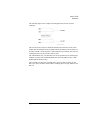
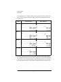
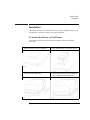
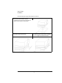
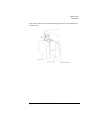
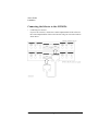
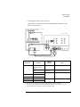
User’s Guide
Agilent 16440A SMU/Pulse Generator Selector
Agilent Part No. 16440-90000
Printed in Japan
January 2000
Edition 4
Legal Notice
The information contained in this document is subject to change without notice.
Copyright © 1994 - 2000 Agilent Technologies
This document contains information which is protected by copyright. All rights are
reserved. Reproduction, adaptation, or translation without prior written permission
is prohibited, except as allowed under the copyright laws.
•
Product Warranty
Agilent Technologies warrant Agilent Technologies hardware, accessories and
supplies against defects in materials and workmanship for the period of one year
from the warranty start date specified below. If Agilent Technologies receive
notice of such defects during the warranty period, Agilent Technologies will, at
its option, either repair or replace products which prove to be defective.
Replacement products may be either new or like-new.
Warranty service of this product will be performed at Agilent Technologies.
Buyer shall prepay shipping charges to Agilent Technologies and Agilent
Technologies shall pay shipping charges to return the product to Buyer.
However, Buyer shall pay all shipping charges, duties, and taxes for products
returned to Agilent Technologies from another country.
Agilent Technologies do not warrant that the operation of Agilent Technologies
products will be uninterrupted or error free. If Agilent is unable, within a
reasonable time, to repair or replace any product to a condition as warranted,
customer will be entitled to a refund of the purchase price upon prompt return of
the product.
The Agilent Technologies products may contain remanufactured parts
equivalent to new in performance or may have been subject to incidental use.
The warranty period begins on the date of delivery or on the date of installation
if installed by Agilent Technologies. If customer schedules or delays Agilent
Technologies installation more than 30 days after delivery, warranty begins on
the 31st day from delivery.
Warranty does not apply to defects resulting from (a) improper or inadequate
maintenance or calibration, (b) software, interfacing, parts or supplies not
supplied by Agilent Technologies, (c) unauthorized modification or misuse, (d)
operation outside of the published environmental specifications for the product,
or (e) improper site preparation or maintenance.
2
Agilent 16440A User’s Guide, Edition 4
To the extent allowed by local law, the above warranties are exclusive and no
other warranty or condition, whether written or oral, is expressed or implied and
Agilent Technologies specifically disclaim any implied warranties or conditions
of merchantability, satisfactory quality, and fitness for a particular purpose.
Agilent Technologies will be liable for damage to tangible property per incident
up to the greater of $300,000 or the actual amount paid for the product that is the
subject of the claim, and for damages for bodily injury or death, to the extent
that all such damages are determined by a court of competent jurisdiction to
have been directly caused by a defective Agilent Technologies product.
To the extent allowed by local law, the remedies in this warranty statement are
customer’s sole and exclusive remedies. Expect as indicated above, in no event
will Agilent Technologies or its suppliers be liable for loss of date or for direct,
special, incidental, consequential (including lost profit or date), or other damage,
whether based in contract, tort, or otherwise.
For consumer transactions in Australia and New Zealand: the warranty terms
contained in this statement, except to the extent lawfully permitted, do not
exclude, restrict or modify and are in addition to the mandatory statutory rights
applicable to the sale of this product to you.
•
Assistance
Product maintenance agreements and other customer assistance agreements are
available for Agilent Technologies products.
For any assistance, contact your nearest Agilent Technologies Sales Office.
•
Certification
Agilent Technologies Inc certifies that this product met its published
specifications at the time of shipment from the factory. Agilent further certifies
that its calibration measurements are traceable to the National Institute of
Standards and Technology (NIST), to the extent allowed by the Institute’s
calibration facility, and to the calibration facilities of other International
Standards Organization members.
•
Safety Summary
The following general safety precautions must be observed during all phases of
operation, service, and repair of this instrument. Failure to comply with these
precautions or with specific warnings elsewhere in this manual may impair the
protections provided by the equipment. In addition, it violates safety standards
of design, manufacture, and intended use of the instrument. Agilent
Technologies Inc. assumes no liability for customer’s failure to comply with
these requirements.
Agilent 16440A User’s Guide, Edition 4
3
•
GROUND THE INSTRUMENT
This is Safety Class I instrument. To minimize shock hazard, the instrument
chassis and cabinet must be connected to an electrical ground. The power
terminal and the power cable must meet International Electrotechnical
Commission (IEC) safety standards.
•
DO NOT OPERATE IN AN EXPLOSIVE ATMOSPHERE
Do not operate the instrument in the presence of flammable gases or fumes.
Operation of any electrical instrument in such an environment constitutes a
definite safety hazard.
•
KEEP AWAY FROM LIVE CIRCUITS
Operation personnel must not remove instrument covers. Component
replacement and internal adjustments must be made by qualified
maintenance personnel. Do not replace components with power cable
connected. Under certain conditions, dangerous voltages may exist even
with the power cable removed. To avoid injuries, always disconnect power
and discharge circuits before touching them.
•
DO NOT SERVICE OR ADJUST ALONE
Do not attempt internal service or adjustment unless another person, capable
of rendering first aid and resuscitation, is present.
•
DO NOT SUBSTITUTE PARTS OR MODIFY INSTRUMENT
Because of the danger of introducing additional hazards, do not install
substitute parts or perform any unauthorized modification to the instrument.
Return the instrument to a Agilent Technologies Sales and Service Office for
services and repair to ensure that safety features are maintained.
•
DANGEROUS PROCEDURE WARNINGS
Warnings, such as example below, precede potentially dangerous procedures
throughout this manual. Instructions contained in the warnings must be
followed.
WARNING
Dangerous Voltage, capable of causing death, are present in this instrument.
Use extreme caution when handling, testing, and adjusting.
4
Agilent 16440A User’s Guide, Edition 4
•
Safety Symbols
The general definitions of safety symbols used on equipment or in manuals are
listed below.
Instruction manual symbol: the product will be marked with this symbol when it
is necessary for the user to refer to the instruction manual in order to protect
against damage to the instrument.
Indicates dangerous voltage and potential for electrical shock. Do not touch
terminals that have this symbol when instrument is on.
Protective conductor terminal. For protection against electrical shock in case of
a fault. Used with field wiring terminals to indicate the terminal which must be
connected to ground before operating equipment.
Frame or chassis terminal. A connection to the frame (chassis) of the equipment
which normally includes all exposed metal structures.
Indicates earth (ground) terminal.
Alternating current.
Direct current.
ON (Supply).
OFF (Supply).
STANDBY (Supply).
CAT 1
Means INSTALLATION CATEGORY I. Measurement terminals on the rear
panel comply with INSTALLATION CATEGORY I.
WARNING
The warning sign denotes a hazard. It calls attention to a procedure, practice,
condition or the like, which, if not correctly performed or adhered to, could result in
injury or death to personal.
CAUTION
The caution sign denotes a hazard. It calls attention to an operating procedure,
practice, condition or the like, which, if not correctly performed or adhered to, could
result in damage to or destruction of part or all of the product.
Agilent 16440A User’s Guide, Edition 4
5
•
Herstellerbescheinigung
GEÄUSCHEMISSION
Lpa < 70 dB
am Arbeitsplatz
normaler Betrieb
nach DIN 45635 T. 19
•
Manufacturer’s Declaration
ACOUSTIC NOISE EMISSION
Lpa < 70dB
operator position
normal operation
per ISO 7779
Printing History
Edition 1:
February 1994
Edition 2:
April 1995
Edition 3:
August 1997
Edition 4:
January 2000
6
Agilent 16440A User’s Guide, Edition 4
User's Guide
Agilent 16440A User’s Guide, Edition 4
User's Guide
Agilent 16440A SMU/Pulse Generator Selector is one of the accessories available
for Agilent 4155/4156 Semiconductor Parameter Analyzers. The selector is for
automatically switching the unit (SMU or PGU) that is connected to a DUT pin
according to the state (stress force state or measurement state).
NOTE
To use the selector, the 4155/4156 must be equipped with Agilent 41501 SMU/pulse
generator expander that contains two PGUs.
This manual consists of the following sections.
•
Introduction
•
Operation
•
Installation
•
Maintenance
•
Specifications
2
Agilent 16440A User’s Guide, Edition 4
User's Guide
Introduction
Introduction
The 16440A selector contains the following accessories:
Description
Agilent
Part Number
Quantity
1
SMU/Pulse Generator Selector
16440A
1
2
40 cm triaxial cable
04155-61605
2
3
(option 001) 1.5 m control cable
04155-61612
1
(option 002) 3 m control cable
04155-61611
1
(option 003) 40 cm control cable
04155-61608
1
16440-60001
2
4 plate a
5
(option 001/002) angle b
16440-60002
2
6
(option 001/002) User's Guide (this document)
16440-90000
1
a. Three screws are furnished for each plate.
b. Two screws are furnished for each angle.
NOTE
Inspecting the 16440A upon Receiving
When the 16440A arrives at your site, make sure that nothing is missing or
damaged. Unpack the carton, then check the contents against figure and table above.
If anything is missing or damaged, contact your nearest Agilent Technologies sales
office.
Agilent 16440A User’s Guide, Edition 4
3
User's Guide
Operation
Operation
This section describes the operating theory of the selector.
Agilent 4155/4156 can control the selector to automatically switch the unit (SMU or
PGU) that is connected to a DUT pin according to the state (stress force state or
measurement state).
This is useful for performing reliability testing (stress testing) of DUTs. For
example, the selector can connect a PGU to the DUT for forcing ac stress, then can
switch and connect an SMU for measuring dc characteristics.
You define the selector connections in SMU/PG SELECTOR table on the STRESS:
CHANNEL DEFINITION page. The switching state specified in the STRESS
column is automatically performed during stressing. The switching state specified in
the MEASURE column is automatically performed during measurement. See
"STRESS: CHANNEL DEFINITION screen" in the 4155/4156 User's Guide.
For example, you can specify to connect the PGU to the DUT during stress, and
connect the SMU to the DUT during measurement. So, when you press the Stress
key, the PGU is automatically connected to the DUT. And when you press a
measurement key, the SMU is automatically connected to the DUT.
The 4155/4156 controls the switching of the selector.
Each selector has two channels. If you want to add two more channels for a total of
four, you can order 16440A option 003, which is called the "selector expander".
The selector and selector expander have identical circuits. The only difference is the
channel naming. The selector has CH 1 and CH 2, and the selector expander has CH
3 and CH 4.
4
Agilent 16440A User’s Guide, Edition 4
User's Guide
Operation
The following figure shows a simple circuit diagram of the selector (selector
expander).
The CH 1 and CH 3 circuits are different from the CH 2 and CH 4 circuits. Each
channel has one mechanical relay for SMU and one mechanical relay for PGU, but
the CH 1 and CH 3 circuits also have a semiconductor relay for PGU. The relays are
controlled by the 4155/4156 via the control circuit.
The semiconductor relay is useful when you need to perform a lot of switching (for
example, read/write tests of flash ROM) because the semiconductor relay is more
durable than mechanical relays.
CH 1 and CH 3 can have four switching states: all open, SMU on, PGU on, and
PGU open. CH 2 and CH 4 can have three switching states: all open, SMU on, and
PGU on.
Agilent 16440A User’s Guide, Edition 4
5
User's Guide
Operation
The switching state of a channel is indicated by the green LEDs on the selector front
panel. The following table shows the relation of the relays and the LEDs for each
switching state.
States
CH 1 and CH 3
CH 2 and CH 4
All open
SMU on
PGU on
PGU open
The "PGU open" state is useful if a lot of switching needs to be performed. When
the switching state changes from "PGU on" to "PGU open", only the semiconductor
relay switches. This reduces the amount of times the mechanical relay is switched.
The semiconductor relay has a much longer switching life than the mechanical relay.
6
Agilent 16440A User’s Guide, Edition 4
User's Guide
Installation
Installation
This section describes how to attach the selector to Agilent 16442A test fixture or to
a shielding box, and how to connect it to Agilent 4155/4156.
To Attach the Selector to Test Fixture
You can attach your selector to the 16442A test fixture. You need a standard
screwdriver.
1. Place the selector on your workbench.
2. Place the test fixture on top of the selector.
3. Position a plate on both sides.
4. Attach each plate using the three flathead
screws supplied with the instrument.
Agilent 16440A User’s Guide, Edition 4
7
User's Guide
Installation
The following steps apply when using two selectors:
5. Place the second selector on your
workbench. Place the selector and the test
fixture on top of the second selector.
6. Position a plate on both sides.
8
7. Attach each plate using the three flathead
screws supplied with the instrument.
Agilent 16440A User’s Guide, Edition 4
User's Guide
Installation
If you use the 16441A R-box, attach the R-Box to the selector as shown below:
Agilent 16440A User’s Guide, Edition 4
9
User's Guide
Installation
To Attach the Selector to Shielding Box
You can attach your selector to a shielding box. You need a standard screwdriver.
The following figure shows the spacing of the 16440A screw holes. You need to
prepare four screws and nuts to match the screw holes.
10
Agilent 16440A User’s Guide, Edition 4
User's Guide
Installation
If you use two selectors, connect selectors before attaching to the shielding box, as
shown below:
1. Place the selector on your workbench.
2. Place the second selector on top of the
selector.
3. Position a plate on both sides.
4. Attach each plate using the three flathead
screws supplied with the instrument.
Agilent 16440A User’s Guide, Edition 4
11
User's Guide
Installation
Attach the selector to the shielding box as shown below:
1. Attach an angle bracket to each side of the selector, using the screws supplied.
2. Place the selector(s) on the side panel of
the shielding box.
3. Position four nuts on the inside panel of
the shielding box.
4. Attach the angle bracket to the shielding
box using four flathead screws.
12
Agilent 16440A User’s Guide, Edition 4
User's Guide
Installation
If you use the 16441A R-box, attach the R-Box to the selector on the shielding box
as shown below:
Agilent 16440A User’s Guide, Edition 4
13
User's Guide
Installation
Connecting the Selector to the 4155/4156
•
Connecting two selectors
If you use two selectors, connect the Control Output terminal of the selector to
the Control Input terminal of the second selector using a 40 cm control cable as
shown below.
14
Agilent 16440A User’s Guide, Edition 4
User's Guide
Installation
•
Connecting the selector to the 4155/4156
Turn off the 4155/4156 and 41501 before connecting the instruments. Then
connect as shown below.
4155/4156
16442A Test Fixture
4
2
41501
16440A Selector
3
1
16440A
Terminal
Cable
To SMU/Pulse
Generator Selector
Interface
CONTROL Input
3.0 m or 1.5 m Control Cable
PGU
Input PGU a
3.0 m or 1.5 m Coaxial Cable
MPSMU or HPSMU
Input SMU
3.0 m or 1.5 m Triaxial Cable
Output Selected b
40 cm Triaxial Cable
Instrument
41501
Terminal
4155
MPSMU
4156
HRSMU
16442A
SMU
Connector Plate
SMU
a. You can use two inputs for one selector, and four inputs for two selectors.
b. You can use two outputs for one selector and four outputs for two selectors. Selector
output is either one of the PGU outputs or the SMU output.
Agilent 16440A User’s Guide, Edition 4
15
User's Guide
Maintenance
Maintenance
This section provides the following maintenance information:
•
Cleaning
•
Servicing
Cleaning the Selector
To maintain high performance, the selector must be kept clean. Oil, perspiration,
hair, dust, and dirt will degrade the board insulation, which increases leakage
current and decreases measurement accuracy.
Agilent Technologies recommend the following cleaning procedure:
1. Make sure that voltage or current is not present at any channel.
2. Disconnect all cables from the selector.
3. Using lint-free paper, gently wipe the chassis. For any area that will not come
clean, dip the lint-free paper into alcohol and wipe the area gently.
Servicing the Selector
This section provides information for trained service personnel to repair the selector.
When a replaceable part, which is shown with the Agilent part number in this
section, needs to be replaced, order the parts from the nearest Agilent Technologies
Sales and Service Office.
WARNING
High voltages may be present in the selector when voltage or current is applied.
Be careful to avoid electric shock.
Before you repair the selector, make sure that terminals are not connected to any
instrument.
16
Agilent 16440A User’s Guide, Edition 4
User's Guide
Maintenance
Circuit Block Diagram
Agilent 16440A User’s Guide, Edition 4
17
User's Guide
Maintenance
Replaceable Parts
When soldering, use low hydrochloric acid solder (Agilent part number: 8090-0433)
to prevent the flux in the solder from spreading unnecessarily, and make sure that
adjacent terminals are not bridged. After soldering, make sure that there are no lint
bridges, which would increase the leakage current.
Reference
Designation
Agilent
Part Number
Description
R1
0757-0442
Resistor 10 kW, 1%, 0.125 W
R6
0698-3440
Resistor 196 W, 1%, 0.125 W
R7
0757-0402
Resistor 110 W, 1%, 0.125 W
R8
0698-3440
Resistor 196 W, 1%, 0.125 W
R9
0698-3440
Resistor 196 W, 1%, 0.125 W
R12
0698-0085
Resistor 2.61 kW, 1%
18
Agilent 16440A User’s Guide, Edition 4
User's Guide
Maintenance
Reference
Designation
Agilent
Part Number
Description
R13
0698-0085
Resistor 2.61 kW, 1%
R15
0757-0279
Resistor 3.16 kW, 1%
CR1
1901-0050
Diode
CR2
1901-0050
Diode
CR3
1901-0050
Diode
CR4
1901-0050
Diode
L1
9140-0210
Inductor 100 mH ±5%
C1
0180-3468
Capacitor 47 mF 50 V
CP1
1990-1625
Opto-isolator
CP2
1990-1625
Opto-isolator
K1
0490-1791
Reed Relay
K2
0490-1791
Reed Relay
K3
0490-1791
Reed Relay
K4
0490-1791
Reed Relay
DS8
1990-0967
LED Green
DS9
1990-0967
LED Green
DS10
1990-0967
LED Green
DS11
1990-0967
LED Green
DS12
1990-0967
LED Green
J1
1252-1481
Connector
J2
1250-1842
Connector BNC
J3
1250-1842
Connector BNC
J4
1252-1481
Connector
SW1
3101-2885
Switch - DIP
I1
0360-1641
Terminal
I2
0340-0060
Terminal
I3
0360-1641
Terminal
I4
0340-0060
Terminal
Agilent 16440A User’s Guide, Edition 4
19
User's Guide
Specifications
Specifications
The "supplemental information" and "typical" entries, in the following
specifications are not warranted, but provide useful information about the functions
and performance of the instruments.
The following specifications data is specified at 23 ± 5 °C and 50 % relative
humidity.
•
Function
Agilent 16440A switches either a SMU or PGU to the associated output port.
You can expand to 4 channels by adding an additional 16440A. The channel 1
PGU port provides "PGU OPEN" function, which can disconnect the PGU by
opening a semiconductor relay. The 16440A can not work without two pulse
generator units of Agilent 41501 SMU and Pulse Generator Expander.
•
Channel configuration: 2 channels (CH1 and CH2). Can add additional 2
channels (CH3 and CH4) by adding another 16440A (selector expander).
Input
Output
Channel 1 (CH 1)
2 (SMU and PGU)
1
Channel 2 (CH 2)
2 (SMU and PGU)
1
Channel 3 (CH 3) a
2 (SMU and PGU)
1
Channel 4 (CH 4) a
2 (SMU and PGU)
1
a. These channels are available when an 16440A SMU/PG selector
expander is installed.
•
Voltage and current range
Input port
Maximum Voltage
Maximum Current
SMU
200 V
1.0 A
PGU
40 V
0.2 A a
a. This is peak-to-peak ac current.
20
Agilent 16440A User’s Guide, Edition 4
User's Guide
Specifications
•
Accessories (furnished). See Section 1 for details.
•
•
•
•
Option 001
•
1.5 m control cable (Agilent part number 04155-61612)
•
40 cm triaxial cable (Agilent part number 04155-61605)
Option 002
•
3.0 m control cable (Agilent part number 04155-61611)
•
40 cm triaxial cable (Agilent part number 04155-61605)
Option 003
•
40 cm control cable (Agilent part number 04155-61608) for connecting
selector to selector expander
•
40 cm triaxial cable (Agilent part number 04155-61605)
General specifications
•
•
Environment
Operating temperature
5 °C to 40 °C
Storage temperature
-40 °C to 70 °C
Operating Humidity
5 % to 80 % relative humidity
(at no condensation)
Storage Humidity
5 % to 90 % relative humidity at 65 °C
Weight
Approximately 1.1 kg (2.43 lb)
Agilent 16440A User’s Guide, Edition 4
21
User's Guide
Specifications
Supplemental Information
The following reference data is specified at 23 ± 5 °C (73 ± 9 °F) and 50 % relative
humidity.
•
•
SMU channel
Leakage current
less than 100 fA at 100 V
Residual resistance
0.2 W typical
Stray capacitance
(force common)
0.3 pF typical at 1 MHz
Stray capacitance
(force guard)
15 pF typical at 1 MHz
Stray capacitance
(guard common)
130 pF typical at 1 MHz
PGU channel
Residual resistance
3.4 W
Stray capacitance
(relay off)
5 pF typical
Stray capacitance
(open)
700 pF typical (at 1 MHz Vin - Vout = 0 V)
Signal transfer
characteristics
22
Overshoot < 5 % of pulse amplitude (at 20 ns leading
and trailing time, 50 W pulse generator source
impedance, 50 pF 1 MW in parallel load)
Agilent 16440A User’s Guide, Edition 4