1
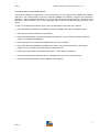
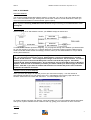
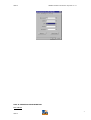
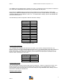
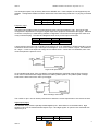
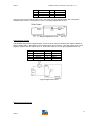
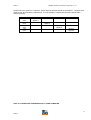
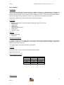
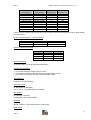
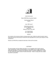
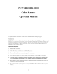
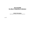
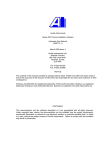
Anville Instruments
Series 425/X-425 Data Acquisition System
User Manual
(QMF 33)
May 2004 Issue 12
Anville Instruments Ltd
Unit 19, Pegasus Court
North Lane, Aldershot
Hants, GU12 4QP
Tel. 01252 351030
Fax. 01252 323492
Enquiries & Support: [email protected]
NOTICE
The contents of this manual are liable to change without notice. Whilst every effort has been made to
ensure the accuracy of this manual, Anville will not be responsible for any errors and omissions or their
consequence.
Windows, Excel and MS-DOS are registered trademarks of Microsoft Corporation.
Lotus 123 is a registered trademark of IBM.
IBM is the registered trademark of International Business Machines Corporation.
SCAN1000 is the registered trademark of Hexatec
COPYRIGHT
This documentation and the software described in it are copyrighted with all rights reserved.
Under copyright laws, neither the documentation nor the software may be copied, photocopied,
reproduced, translated, or reduced to any electronic medium or machine readable form, in whole
or in part, without the written consent of Anville Instruments. Failure to comply with this condition
may result in prosecution.
QMF 33
SERIES 425/X425 User Manual. May 2004. Iss. 12
CONTENTS
PART I:
INTRODUCTION TO THE SERIES 425
PART II:
SOFTWARE INSTALLATION
PART III:
SERIES 425 CONFIGURATION
PART IV: CONNECTING THE SERIES 425 TO YOUR COMPUTER
PART V:
SOFTWARE ENVIRONMENT
PART VI: QUICK START/OPERATING INSTRUCTIONS
PART VII: WARNING AND ERROR MESSAGES
PART VIII: SPECIFICATIONS
2
QMF 33
QMF 33
SERIES 425/X425 User Manual. May 2004. Iss. 12
AN OVERVIEW OF THIS USER MANUAL
This manual is divided into eight parts. Part I introduces you to an overview of the SERIES 425. Starting
with Part II, the manual shows you how to install the SERIES 425 software, configure and operate the
equipment. After mastering the system, you can use the manual as a handy reference. When you need
help with a specific problem, turn to the appropriate area of the manual that describes that part of the
system.
To give you an idea of the manual’s layout, here is a description of each part of the manual:
• Part I describes the hardware and software for both the SERIES 425 and the computer system.
• Part II tells you how to install the X-425 software.
• Part III describes system hardware configuration and tells you how to connect the different types of
sensors using tables and diagrams.
• Part IV tells you how to connect the SERIES 425 unit to your computer.
• Part V talks about the SERIES 425 software environment; how to start and exit from the logging
program; how to configure the system using the dialogue boxes.
• Part VI gives you a quick start to operate the system. (with reference to Part III).
• Part VII lists and explains warning and error messages that may occur from time to time.
• Part VIII provides specifications for the SERIES 425 equipment.
3
QMF 33
QMF 33
SERIES 425/X425 User Manual. May 2004. Iss. 12
PART I: INTRODUCTION TO SERIES 425
OVERVIEW
Welcome to the SERIES 425 group of Data Acquisition Units. Each unit consists of two parts, the
hardware and the software. Hardware is all the physical parts of the unit including a compatible computer
system. Software is the logging application that interacts with your hardware. Hardware and software work
together to automate the unit’s configuration and operation. Instructions are simple to follow. The complete
system is easy to set-up and easy to use.
The SERIES 425 is connected to a compatible computer system which provides the X-425’s software
operating environment working under MS-DOS, Windows 3.x, Windows for Work Groups, Win’95 and
Windows NT. Please note that descriptions and instructions are with reference to Windows ‘95.
Hardware
The compact hardware provides thermocouple and general purpose analogue inputs, which you configure
to meet your requirements along with digital inputs and outputs for simultaneous logging and alarm setting.
Connection to a computer, using the supplied cable, is made via an RS422/423 serial link. An additional
RS422/423 connector allows you to ‘daisy-chain’ two SERIES 425s together if more analogue inputs are
needed. The SERIES 425’s internal microprocessor converts all inputs into their correct engineering units
for transmission to the host computer.
Unit Versions
SERIES 425-0 provides 16 general purpose inputs.
SERIES 425-4 provides 4 thermocouple and 12 general purpose inputs.
SERIES 425-8 provides 8 thermocouple and 8 general purpose inputs.
SERIES 425-12 provides 12 thermocouple and 4 general purpose inputs.
SERIES 425-16 provides 16 thermocouple inputs.
System Software
Two software packages run and automate data acquisition; SCAN1000 and X-425 configuration software.
SCAN1000 is supplied on 5 diskettes and X-425 on 2 diskettes for installation to your computer’s hard
disk. See Part II: SOFTWARE for installation and set-up instructions. Both software packages running
under Windows provide all facilities for your system and gives you easy mouse operated control.
ser Manuals
In addition to this manual, you are provided with Scan1000 Introductory Guide. A Scan1000 Help file
forms part of the software package providing general support information, read alone and on-line help
accessed as you use the software.
COMPATIBLE COMPUTER SYSTEM
Any currently available computer having a Pentium or similar processor. The computer, whether a desktop
or portable model should contain CD and floppy disk drives, printer port and a COM port (9-pin D type
connector). The COM port is used to connect the data logger to the computer. Some computers have a
USB connector fitted instead of the 9-pin D connector. In this case a USB package, comprising a cable
and USB driver software CD must be acquired. Please consult your IT department for help to configure
your computer to enable the USB port. The USB cable is then used to connect the data logger and
computer together.
4
QMF 33
QMF 33
SERIES 425/X425 User Manual. May 2004. Iss. 12
PART II: SOFTWARE
Scan1000 Software
You must first install SCAN1000 software (5 disks). Insert disk 1 in A drive (or B). Click Start and then
Run. In the Command Line type ‘A:Setup.exe’ and click OK. Follow on-screen instructions. When you
reach the screen that asks for a serial number, type in 0 (zero).
Note: If you are installing SCAN1000 under Windows NT you must log on as Administrator when
starting NT.
X-425 Software
Before installing the X-425 software connect your SERIES 425(s) as shown here.
To install X-425 software repeat the foregoing. As you progress through the installation you will be asked
for your fax number; if you have 1 or 2 Series 425 boxes connected; to what computer COMs port they
will be connected. Please answer accordingly. However, when you are asked whether or not you will be
running Excel select No.
If you have initially set up your system for a single Series 425 but would like to connect another
box, you must first un-install the current X-425 software, connect the additional box and then
reinstall X-425 software. Your configuration settings of the first box will be retained. To remove
software you must run Uninstall X-425 System routine from the X-425 program. Click Start,
Program,X-425, Uninstall X-425 System. Do not attempt to remove the X-425 System via Windows
Explorer. Near the end of installation procedure you will be asked if you wish to apply for another
license. Click NO. If you want to install X-425 software onto another PC please refer to Hexatec
Installation Procedures document.
Software Licence (Licence-Notepad)
When you reach this stage it is vital that you fill in your name and company. Your fax number is
automatically inserted but you can change it for your e-mail address. Print out the page and fax it to
Hexatec. Actions are in the menu bar: File, Print. To close notepad: File, Exit.
On receipt, Hexatec will send your Site-Key which will enable you to run the software without interruption.
Until you do, system software will run in demo mode only, giving you a maximum run time of 2 hours.
Site-Key
5
QMF 33
QMF 33
SERIES 425/X425 User Manual. May 2004. Iss. 12
When you receive the Site-Key, open Enter Site-Key file from the X-425 program and enter the details.
Click the Activate button to finish. You will then get conformation that the Site-Key has been accepted.
SERIES 425 Units
Click the radio button that applies. Please note that if you wish to connect a second logger you must first
uninstall then reinstall the software. Do this after you have connected the additional logger to the system.
See X-425 Software above.
COMs Ports
Click the COM port that you will be using. COM 2 is the default. Some Computers use COM 1 for the
mouse. For help on COM ports please refer to PART I: INTRODUCTION TO THE SERIES 425,
Compatible Computer System, System Unit and Memory.
Select Components
When you reach this point it is the end of software installation. You will be asked if you would like to
configure the 425 units now or later. The choice is yours.
Setup Complete
When installation is finished, an Information dialogue box appears telling you this but also tells you how to
enter your Site-Key when it arrives. Make a note if you wish. Click OK.
Once installation is complete the X-425 Program is created containing the files shown here, to run your
system.
Communications Protocol
The protocol that enables the SERIES 425 to talk to X-425 software via your PC is automatically set during
the installation process. For your information protocol details are given below.
Windows COMs Port Settings
For the software to communicate with a Series 425 via a COMs port, the port must be set up using the
correct protocol. The chosen COMs port should be set, as shown here using Start, Settings, Control
Panel. Click on the System icon and then select Device Manager tab. From there choose Ports (COM &
LPT). Highlight the COMs port required, click on the Properties button. Select Port Settings tab and in the
COMs Properties dialogue box make the settings.
6
QMF 33
QMF 33
SERIES 425/X425 User Manual. May 2004. Iss. 12
PART III: SERIES 425 CONFIGURATION
Box Address
7
QMF 33
QMF 33
SERIES 425/X425 User Manual. May 2004. Iss. 12
Your SERIES 425 is supplied with its’ address set to zero. An address is set by the positions of switches 1
to 4 of the UNIT CONFIGURATION switch array. See SERIES 425 side panel.
If more than one SERIES 425 is to be used on the computer port, it will be necessary to alter switch
settings of any additional SERIES 425s thus providing each one with a unique address. For example, box
1 will have address 0, box 2 address 1 and so on. To initialise switch settings, power to the SERIES 425
must be turned off then on.
The table below provides configuration address and switch settings.
Switch setting
1 2 3 4
on on on on
off on on on
on off on on
off off on on
on on off on
off on off on
on off off on
off off off on
on on on off
off on on off
on off on off
off off on off
on on off off
off on off off
on off off off
off off off off
Unit address
0
1
2
3
4
5
6
7
8
9
10
11
12
13
14
15
Unit Configuration Table
Communication Baud Rate
Your SERIES 425 is supplied with baud rate set to 9600. If you need to change the baud rate, use
switches 5 and 6 of the UNIT CONFIGURATION switch array. The following table gives switch settings for
specific baud rates. To initialise switch settings, power to the SERIES 425 must be turned off then on.
Please note that whichever baud you configure, you must also set the same baud in Windows Control
Panel to match. See below how to do this.
Switch settings
5 6
on on
off on
on off
off off
Baud rate
1200
2400
9600
19200
Communication Format
The communication format is fixed and will consist of 8 data bits, 1 stop bit, no parity, flow control- none.
Please note that if you are not using the SERIES 425’s software it is very important that you set the
communication format and baud rate for the chosen serial port using WINDOWS Start, Settings, Control
Panel before operating the SERIES 425.
Analogue Outputs (option)
8
QMF 33
QMF 33
SERIES 425/X425 User Manual. May 2004. Iss. 12
Two analogue outputs may be factory fitted to the SERIES 425. These outputs are not supported by the
software. Configuration details are shown below with connections being made via a 4- pin plug in terminal
block.
Pin no.
1
3
Signal name
anout ground
anout ground
Pin no.
2
4
Signal name
anout 2
anout1
Frequency Input
The Series 425 provides inputs for measuring both pulse count and frequency (Hz). The type of input
configuration is dependent on the type of signal output from equipment connected to the logger. Selection
of counter or frequency is made during software configuration. Connections to the logger are made via a
4-way screw block plug. The table and diagrams below show pin and input connections.
Pin No.
1
3
Signal Name
+5V output
trig. level
Pin No.
2
4
Signal Name
input
ground
A logic level/uni-polar input with a signal level of between 0V to 5V (CMOS/TTL) would (generally) use the
connections shown in the Logic Level Input Circuit diagram. 0V to 2.4V ±100mV = logic 0; 2.6 ±100mV to
5V = logic 1. Pulse count input has a range of 0 to 65535 counts. Counts are not cumulative; each ‘new’
count will replace the previous count.
Logic Level Input Circuit
An AC signal/bi-polar input, from 0 to 65Khz, would (generally) be measured using the Zero Crossing
Level circuit connections with voltage levels from 100mV peak-to-peak to 10V peak-to-peak. Voltage
levels below 100mV will not be ‘seen’ by the logger.
Zero Crossing Level Circuit
The +5VDC on pin 1 can be used to power devices where the current requirement is not more than 5mA.
Digital Inputs (digin)
The SERIES 425 provides 8 optically isolated digital inputs. With reference to the table below, digin
signals on pins 2-5 are measured with respect to pin 1 and digin signals on pins 5-8 are measured with
respect to pin 6.
Pin
1
Signal name
ground
Pin
6
Signal name
ground
9
QMF 33
QMF 33
SERIES 425/X425 User Manual. May 2004. Iss. 12
2
3
4
5
digin 1
digin 2
digin 3
digin 4
7
8
9
10
digin 5
digin 6
digin 7
digin 8
The input connector provides access to one end of the LED of an optical isolator with a 4K7 series
resister to limit current. Connections are via a 10-pin plug supplied with the unit.
A typical digital input circuit
Digital Outputs (Digout)
The SERIES 425 provides 8 digital outputs. These are open collector transistor type outputs capable of
directly driving relays. With reference to the table below, digout on pins 2-5 are with respect to pin 1 and
digout on pins 5-8 are with respect to pin 6. Connections are via a 10- pin plug supplied with the unit.
Pin no.
1
2
3
4
5
Signal name
ground
digout 1
digout 2
digout 3
digout 4
Pin no.
6
7
8
9
10
Signal name
ground
digout 5
digout 6
digout 7
digout 8
A typical digital output circui
Digital Output Arrangement
10
QMF 33
QMF 33
SERIES 425/X425 User Manual. May 2004. Iss. 12
Outputs are set in groups of 4 channels. When digout is ON all channels are switched on. Likewise when
digout is OFF all channels are switched off. It is not possible to combine ON and OFF outputs within
channel grouping.
OUTPUT
ON
OFF
ON
OFF
ON
OFF
ON
OFF
CHAN 1-4
digout 1
digout 2
CHAN 5-8
CHAN 9-12
CHAN 13-16
digout 3
digout 4
digout 5
digout 6
digout 7
digout 8
PART IV: CONNECTING THE SERIES 425 TO YOUR COMPUTER
11
QMF 33
QMF 33
SERIES 425/X425 User Manual. May 2004. Iss. 12
IMPORTANT NOTE: please refer to PART VI: SPECIFICATIONS if you do not intend using the cable
supplied.
NOTE: Pins 6 and 8, pins 7 and 8 of the ‘D’ type plug are no longer linked for RS232 or RS422
operation. Units are factory set for the required protocol. However, cables with links fitted can still be
used. Pin configuration details are retained for reference.
The SERIES 425 is supplied with a 2 metre length cable (which meets the requirements of RS232) fitted
with 9 pin 'D' type plug and socket. The system requires transmit (Tx), receive (Rx) and ground
connections for most applications, so these are the only signal connections made in both plug and socket.
Pins 6 and 8 or pins 7 and 8 are linked depending on serial data transmission protocol. Links are made in
the cable plug end that is connected to the logger. Cable wiring details are given below.
Pin
2
3
5
6
7
8
Pins 1,4 and 9 are not used.
Signal name
Tx
Rx
signal ground
RS422 link
RS423 link
+5V
Signal direction
to Computer
from Computer
Wire
white
black
screen
Linked to pin 8
Linked to pin 8
The SERIES 425 has two serial port connectors, SERIAL IN and SERIAL OUT. As a general rule,
SERIAL OUT will be connected to your computer in a single unit installation. Where a second unit is used,
it will be connected into the system by 'daisy chaining' the SERIAL IN to the SERIAL OUT of the first unit.
Cable connections for ‘daisy chaining’ a SERIES 425 are given in the table below.
Pin
2
3
5
6
7
8
Signal name
Tx
Rx
Signal ground
RS422link
RS423 link
+5V
Signal direction
to next 425
from next 425
Wire
white
black
screen
Linked to pin 8
Linked to pin 8
RS422 Transmission
If the overall line length (distance) between your PC and the second daisy-chained logger exceeds 30
metres (approx. 65 feet) an RS422 serial card must be fitted to your PC to maintain signal integrity.
RS422 signal titles and pin connections are given in the table below. In addition the serial cable link
between pins 7and 8 must be removed and pins 6 and 8 linked. See previous table.
Pin
1
2
3
4
5
Signal
Name
Txb
Txa
Rxa
Rxb
ground
Signal Direction
to computer
to computer
from computer
from computer
Power Up
Note: in order to comply with European EMC legislation the Series 425 must be connected to mains earth.
No action is necessary if the supplied mains adapter is used.
12
QMF 33
QMF 33
SERIES 425/X425 User Manual. May 2004. Iss. 12
The SERIES 425 is dc powered requiring +5V at 0.5A and +24V at 0.2A. The unit is normally supplied
with a 230V AC mains adapter which will provide correct input voltages. Power enters the SERIES 425
via the 4 pin connector on the rear panel. Where several units are to be mounted within an enclosure it
may be beneficial to power them from a Common supply. Power connection details are:
Pin
1
2
3
4
Signal name
Earth
0V
+5V
+24V
Front Panel Connection Details
Thermocouple connections are made using miniature plugs and general purpose connections (other
analogue inputs) are made through 9-pin D type plugs supplied with the SERIES 425. Please note that
connections to D type plugs must be soldered. Pin numbers shown are viewed through the plug from the
solder connector side.
Thermocouple Inputs
CAUTION
Where thermocouples are used involving fluids or condensing gases, for example with
Autoclaves, they must be connected to the data logger in one of two ways:
1. At a point lower than the logger, remove at least 2.5cm of insulating material from the
thermocouple wire.
2. Make thermocouple connections to the logger via flying leads, either below logger level or
at a distance of 0.5 metres, with an in-line cable mounting socket attached.
Both of these methods ensure that any liquids migrating up the thermocouple wire due to the
capillary effect, escape before reaching the logger. Serious damage to the logger will result if
liquid is allowed to enter.
General Purpose Analogue Inputs
On all input connectors, +24V dc is available across pins 5 and 9. This voltage is for use with instruments
such as transducers that are unable to respond quickly enough to a pulsed excitation voltage (ref. Fig.4)
and as a result require a permanent supply voltage. Maximum current is 50mA.
13
QMF 33
QMF 33
SERIES 425/X425 User Manual. May 2004. Iss. 12
Figure1: 24Vdc output connections. Current 50mA max.
Figure 2 Voltage input
Figure 3. Current loop input: 4 to 20mA (powered by transmitter or other source e.g.Fig.1)
Figure 4. Current loop input: 4 to 20mA (powered by Series 425 using pulsed voltage output)
Figure 5. Thermocouple input
Note: do not fit link between pins 3 and 7 if using grounded thermocouples
14
QMF 33
QMF 33
SERIES 425/X425 User Manual. May 2004. Iss. 12
Figure 6. Pt100 or resistive inputs
Figure 7. Transducer input
Transducer Connections - 4-20mA output.
Please note that this wiring diagram is an alternative to Figure 4 and should be used if a transducer,
connected as Figure 4 does not respond. The example shows how you would connect a 2-wire transducer
to the unit (Fig.3) using the +24V available from the connector as an excitation voltage.
15
QMF 33
QMF 33
SERIES 425/X425 User Manual. May 2004. Iss. 12
PART V: SOFTWARE ENVIRONMENT
CONFIGURING YOUR SYSTEM
Data Management
Before proceeding its’ worth describing how your data is saved and the types of files that you will
(probably) generate during configuration and when you are running the system software.
Note: All file names are limited to 8 characters but not including the file’s extension. This limit of 8
characters also applies to directory/folder names.
Directory and File Path
The default directory path for saving your files in the X-425 system is C:\SCAN1000\X-425\********.425.
The path is set as follows:
C:\ root directory (generally the hard disk)
\Scan1000 is the main or target directory
\X-425 a sub-directory
\********.425 is the file.
The asterisks represent the name of the file and .425 it’s extension that identifies the file type. All files that
you create are saved in X-425 sub-directory by default.
Changing the default path
You can change this ‘path’ if you wish to. For example: C:\Data\rigsetup.str. On the C drive via Windows
Explorer, create a folder called Data. With the X-425 software running click the Record button. In Data
Logging Store File dialog box that appears delete the current (default path) entry and insert the new details
C:\Data\rigsetup.str. Click OK and data will be saved in rigsetup.str file.
Configuration file: save your configuration setup to this file type, which must always have the extension
.425. For example a setup file name could be RIGSETUP.425. To save your setup file, click over File in
the Configuration Utility menu bar and select the Save As… function. Thereafter use Save if changes are
made to that file. Setup files are automatically placed in your X-425 directory unless you choose another
path.
Store file: the store file is where you will save your logged data and which will always have the extension
.STR. For example a store file name could be RIGSETUP.STR. The file will be located in your X-425
directory. Store files are automatically placed in your X-425 directory unless you choose another path.
Convert file: this file type is used when you would like logged data to be displayed in an Excel
spreadsheet. The file will always have the extension .CSV. For example a file name could be
RIGSETUP.CSV. Conversion is automatic. Converted files are automatically placed in your X-425
directory unless you choose another path.
Configuration
In the X-425 group, double-click on the Configure 425 Units icon. This will bring up the X-425
Configuration Utility dialogue box seen here.
16
QMF 33
QMF 33
SERIES 425/X425 User Manual. May 2004. Iss. 12
The dialogue box has three main areas: X-425, Channel and Frequency Channel. Each area provides
radio buttons for mouse selection or text boxes for typed inputs. The box also contains System Settings,
Data Logging, Display List, Update Scan, About, Logger and Exit buttons. The Menu bar has a File dropdown menu from where you can save your configuration set-up.
X-425.
• Unit 1
• Unit 2
• Read
• Write
Click radio button to configure the first SERIES 425. If you only have one
SERIES 425 connected, the Unit 2 radio button will be greyed out.
Click radio button to configure the second unit.
Click this button to ‘see’ the SERIES 425’s current configuration set-up.
Click this button to write (down-load) your configuration set-up to the SERIES.
425. It is important to do this each time you configure to update the SERIES 425.
Channel.
• Channel:
•
•
•
•
•
•
Click on Next>> button to select channels 1 to 16 forwards.
Click on <<Prev. button to select channels 1 to 16 reverse.
Type
Select a sensor type by clicking on the down arrow and then click on the sensor.
Name
Type in channel identification if required. Click Update Scan when you have finished.
T/C mode Default °C. Use cursor arrow to select °F or °K.
Speed Mode Normal: 8 channels per second.
Fast:
16 channels per second.
Scale
Default 1. Type in a scale factor if needed.
Offset
Default 0. Type in an offset if needed.
Note: due to the way that the Series 425 data loggers have been set up to handle scan rates
of 16 channels /second, noise immunity levels have slightly reduced, causing data readings
to fluctuate due to an increase in noise level. Please select Normal mode where possible. If
red vertical lines appear in the trend graph, it is an indication that the logger is not
responding quickly enough and you should change to the Fast mode. Sensors most
affected are thermocouples.
Frequency Channel.
•
•
•
•
•
Mode
Mode
Name
Scale
Offset
Frequency
Click down arrow to select.
Counter
Click down arrow to select.
Type in identification if wanted. Click Update Scan when you have finished.
Default 1. Type in a scale factor if needed.
Default 0. Type in an offset if needed.
17
QMF 33
QMF 33
SERIES 425/X425 User Manual. May 2004. Iss. 12
Other Buttons
• System Settings
• Data Logging
• Display List
•
Update Scan
• About...
• Exit
Select COM port and set the Time Out period.
A Logging Option dialog box lets you set scan rate.
Displays your configuration details channel by channel.
The list can be printed for a hard copy or saved to a file.
Updates SCAN1000s interface files for compatibility with the configuration file in
use.
X-425 software version details.
Use this button to leave configuration dialogue box.
Menu Bar - File
•
•
•
•
•
•
New
Open
Save
Save As
Saved files
Exit
click to configure a new setup.
click to open any saved configuration file.
click to save current configuration file.
click to save current configuration setup to a different file name.
shows a list of configuration files. Click to open.
leave configuration setup.
Closing down channels
If you are not using all 16 input channels they can be temporarily closed. Closed channels will not appear
in the default mimic referred to in the next section. To shut channels down proceed as follows.
•
Open the Configuration box, click the Data Logging button, then Advanced button in Logging Options
dialog box. In the C:\…\X-425\X-425-1.STP dialog box find the Line… button. Next to the button is the
name of the line to be closed. To select a line click the down cursor. Click Line…
In the dialog box click the Active check box to deactivate the line (remove the tick). The dialog box will
then report that the line is (not active). Save the changes. To reactivate a line repeat the foregoing.
Running the X-425 System
To run the system, go to Start, Programs, X-425 group, Run X-425 System. The default logging screen
will then be displayed. If you have configured your system for a single box then the mimic shown here
will be displayed.
18
QMF 33
QMF 33
SERIES 425/X425 User Manual. May 2004. Iss. 12
If you have configured your system for 2 boxes this style of mimic will be displayed.
Both logging screens display all analogue inputs in array of 16 channels, Frequency Input, and arrays of 8
Digital Inputs and 8 Digital Outputs. In the 2 box example, System #1 (box 1) details are shown but by
clicking the Display System 2 arrow, System #2 (box 2) details can be viewed. Likewise, click Display
System 1 to show System #1 again. Where only one box is connected (although configured for 2 boxes)
System #2 screen will be blank.
Commands Bar
Superimposed on the screen is a Commands function bar. From here you control the data logging system.
The Commands bar will remain visible at all time unless you decide to hide it.
Button functions are:
•
•
•
•
Record
Stop
Setup
Convert
Starts system to log data. Opens store file. Changes mode from Monitoring to Logging.
System stops logging. Reverts to Monitoring mode.
Scan rate can be changed here while logging is in progress.
Click to convert your data files to .CSV format for use with most spreadsheet programs.
19
QMF 33
QMF 33
•
•
Hide
Exit
SERIES 425/X425 User Manual. May 2004. Iss. 12
Click to hide the Commands function bar. To reinstate click over vacated area or Master,
Function Bar from the menu bar.
Leave Scan1000.
Record Button
When you click the Record button a Data Logging Store File dialog box appears. Its’ in this dialog box that
you should type in the name of the file that you want to save data to. The name must not contain more
than 8 characters. The example shows that data is being saved to Test.STR file. Click OK to begin
recording data. Operation mode will change from Monitoring (brown) to Logging (blue).
Please note, with reference to Data Management at the beginning of this section, this dialog box is where
you could select a different folder.
Setup Button
When you click Setup the following Recorder dialog box is displayed.
In the main you will only need to use this Setup Recorder to change scan times, which you can do while
the software is logging data. However the dialog box’s other function areas are also described here:
Action, Scans, and Copy Range.
Action area
•
•
•
•
•
Stop
Monitor
Record
Reload
Restart
stop data logging.
puts logging into Monitor Mode. Trend graph display not available. Bar graph is available.
puts logger in Record Mode. Trend graph now available.
function not available.
function not available.
Scans area
•
•
•
Time
changes the time between scans to the indicated value.
Number
this indicates the number of scans for each line. Default is 100
Reset after the Recorder performs this Number of scans and then stops. Default is 0.
20
QMF 33
QMF 33
SERIES 425/X425 User Manual. May 2004. Iss. 12
Copy Range area
Copy Range enables a range of scans to be set for copying to clipboard for subsequent insertion into word
processor documents or spreadsheets etc if required and is used in conjunction with Recorder, Line dialog
box . For example if you wanted to copy the first 20 scans of a recording session you would set Start to 1
and Finish to 20 and in the menu bar select Edit, Copy and click, say Dataset1. This action copies scans 1
to 20 of Dataset1 to the clipboard. For the contents of Dataset1 you would have selected a group of
channels in Recorder, Line dialog box and In Copyset Set 1. If you had selected 4 lines you
would have copied scans 1 to 20 of channels 1 to 4 to the clipboard.
Buttons
•
•
•
•
Apply
OK
Cancel
Help
click this button to apply your changes. Button is greyed out when not active.
confirms your changes.
shuts down dialog box.
Recorder online help.
Using Convert
To convert a store file for use with Excel spreadsheets click the Convert button. In the dialogue box that
appears enter a name for the file or use the one displayed. Click OK and the file will be automatically
converted ready for Excel use. The subsequent .CSV file will be stored in the X-425 directory, a subdirectory of Scan1000. Open Excel. Find File, Open and locate the converted file etc. Please note that
total contents of your Store file will be converted, which could produce a considerable number of
worksheets. An alternative is to use Convert found in the Scan folder. Please refer to Scan on-line Help.
If when your file is converted, the spreadsheet shows incorrect date and time you will have to set the time
zone setting to suite your actual time zone. The setting is in SetScan, Core Services System Dialogue
Box. Click Help button for additional information.
Trend Graph
To view a trend graph of your data being logged, click on a channel from the Analogue Inputs array and
data, similar to the example will be displayed.
21
QMF 33
QMF 33
SERIES 425/X425 User Manual. May 2004. Iss. 12
If you select any channel from the array of 1 to 8 this page will be displayed. By selecting channels 9 to 16
a second page will be displayed. To view a page from the trend click on Display in the menu bar. From the
drop-down menu choose Trend, #2.
Current scan information is provided at the bottom of the trend page. To return to the logging screen click
the Mimic button.
Digital Inputs
To view digital input functions click on any Digin No in the array. The information displayed shows all 8
inputs in default ON mode.
To make use of digital inputs you must make appropriate connections via the 10-way Digital Input socket
on the side panel of your SERIES 425. A 10-way plug is supplied. Please refer to PART III: SERIES 425
CONFIGURATION, Digital Inputs for wiring details. Any of the inputs that are turned OFF will change from
a band to a thin line and in the default mimic, ON will change to OFF. For help on how to set up the
software for digital inputs please look in Scan Help.
Digital Outputs
To view digital output functions click on any Digout No in the array. The information displayed shows all
8 outputs in default OFF mode.
22
QMF 33
QMF 33
SERIES 425/X425 User Manual. May 2004. Iss. 12
To turn on any digital output, click OFF in the mimic. This will change to ON and in the display, a thin line
will change to a band. To make use of digital outputs you must make appropriate connections via the 10way Digital Output socket on the side panel of your SERIES 425. A 10-way plug is supplied. Please
refer to PART III: SERIES 425 CONFIGURATION, Digital Outputs for wiring details. For help on how to
set up the software for digital outputs please look in Scan Help.
Viewing Store Files (Historic)
Click Start, Programs, Scan1000,Recorder. A Recorder-1 window will be displayed. In the Menu bar click
File, Store File. In the subsequent Open dialog box, locate the Store file that you want in the X-425 folder,
highlight and place it in the File Name text box. Click OK to bring up an X-425 window. On the Menu bar
click Display, Trend, An_In#1 to display trend graph of your store file. An example trend graph is shown
here.
The trend provides details of time, date and scan numbers to right of the window. Centre box provides
scan rate details. The Historic box provides trend graph information related to mouse pointer positions on
the screen. Move the pointer to any part of the graph and the box will display temperature, time, date and
scan number. Other functions are the same as the real time trend graph.
Alarms
23
QMF 33
QMF 33
SERIES 425/X425 User Manual. May 2004. Iss. 12
Two alarms can be set for each data input: above and below. Notification of an alarm in run-time software
is via an alarm bar, which you can call up and which is located across the top of the screen. Additionally
the alarm can be set to change the state of a digital output to drive a relay or some form of external
audible device.
To set an alarm, open Configuration Utility, Data Logging, Advanced, Setup and Edit Alarm. The Alarm 1
set-up box example shows that for Line 1 the alarm limit is set to Above at a level of 26.00 such that
when the signal on Line1 exceeds 26.00 the Recorder will trigger the alarm and notification will occur in the
alarm bar. Similarly with alarm limit set to Below at 20.00 the Recorder will again trigger the alarm. To set
alarms for other lines return to the Setup and select Line, click the down cursor and highlight the required
line. Click Alarm and continue as before. Save your settings as you return to the Configuration box. Other
types of alarm can also be set. See below
Alarms can be recorded to a log device, say a printer by selecting the Log button. Please note that if you
choose log device the appropriate computer COM port must be selected: LPT1 for a printer. To do this
access Setscan, Core Services, System.
Setting the Trend Page Y Axis Scale
24
QMF 33
QMF 33
SERIES 425/X425 User Manual. May 2004. Iss. 12
There are two ways to set the Y axis scaling. One is before running the X-425 software and the other is
while it is running. Scales changed while the system is running will only be retained for the current run and
not saved for another time.
Method 1
The first is via Configuration dialog box. Open the Configuration box, click the Data Logging button, then
Advanced button in Logging Options dialog box. In the C:\…\X-425\X-425-1.STP dialog box find the
Page… button. Next to the Page button is the Trend page text box. Click the down cursor and select the
page on which you wish to change the Y-axis. Click the Page button which will bring up page An_In#1
dialog box. Repeat for page An_In#2. In the Display area of the dialog box locate Max and Min text boxes
and type in your changes e.g. max 50, min –25. This will give you a range of –25 to +50. When you have
finished, save your changes and return to the Configuration dialog box.
Method 2
The other way is from a trend graph’s menu bar. With the system running and viewing a trend, double click
on the Legend detail box to bring up a Recorder Status detail box. Double click on a page name An_In to
get you to the Page Status detail box. When you reach Page Status click Edit, Setup in the menu bar.
Click Page. In the Page dialog box at the bottom, you will find Top and Bottom text boxes which are used
for changing scale settings. Make changes click Apply then OK. You should see scale range changing in
the trend page behind the dialog box
DDE Hot-Linking
Introduction
DDE is an acronym for Dynamic Data Exchange. Hot-linking is method of passing real-time data from one
application to another. This feature is very powerful as allows you to manipulate data in other applications
such as Microsoft Excel and Microsoft Word that may have nothing obviously in common with
Scan1000/X-425 software. Data is picked up from Scan1000/X-425 as it is running and dealt with in many
and varied ways. It is very easy to set up and use. However knowledge of the target application would be
a definite benefit.
Hot-linking to Excel
Ensure that your X-425 system is logging data. Open Excel and start a new worksheet.
Go to the Taskbar and locate and double-click the Interface-0 (HSP) button to bring up interface dialog
box. Please ignore the fact that Postbox is shown in the example. Set-up principle is the same.
25
QMF 33
QMF 33
SERIES 425/X425 User Manual. May 2004. Iss. 12
Using the mouse pointer, highlight the channels that you want in the Analog In column. Go to the Menu bar
and click Edit, Copy. This information is copied to Windows Clipboard.
Go to the Excel spreadsheet. and highlight the number channels, to match those copied from Scan
Interface-0 (HSP), in the column that want data to appear in.
In the menu bar click Edit, Paste Special to bring up the Paste Special dialog box.
In the dialog box select Paste Link:. Click OK. The Hot-linked data will appear in the column of you choice.
26
QMF 33
QMF 33
SERIES 425/X425 User Manual. May 2004. Iss. 12
From this point it’s up to you to use the data as you want.
Re-establishing Hot-links
The worksheet containing DDE hot-links can be saved as a .xls file so that each time you wish to use the
hot-link simply open the saved .xls file. X-425 system must be running of course.
27
QMF 33
QMF 33
SERIES 425/X425 User Manual. May 2004. Iss. 12
PART VI: QUICK START OPERATING INSTRUCTIONS
Introduction
•
•
•
Before starting the X-425 System program you should have read the software and hardware
installation instructions in Parts III, IV and V. If you have yet to configure a Series 425 or you want to
change sensor types open the Configure X-425 System. Refer to Part V: SOFTWARE
ENVIRONMENT for instructions how to do this.
Power up the Series 425 unit(s).
Switch on your PC and open Windows ‘95.
Starting the system- Configuration
•
•
•
•
•
•
•
Click Start, Programs, X-425, Configure X-425.
Click Read Settings if your 425 unit is already configured for your requirements or …
Click New to configure your 425 unit afresh or …
Click File, Open to load a previously saved file.
Click Write Settings button to download the current file configuration to the Series 425.
Click Update Scan to update the X-425.IDK interface for compatibility with the config. file in use.
Click Exit.
Running the system
•
•
•
•
•
•
Click Start, Programs, X-425, Run X-425 System to start and to bring up the X-425 System default
mimic screen. In the mimic, all connected sensor readings will be displayed in the Analogue Input
array. The system will initially be in Monitoring mode.
All Digital Inputs will be set to ON (default).
All Digital Outputs will be set to OFF (default).
Frequency Input will be 0.00 (default).
To start logging, click the Record button in the Commands function bar.
In the Data Logging Store File dialogue box that appears, type in your store file name. For example
C:\SCAN1000\X-425\TEST.STR where TEST.STR will be your store file. File name to be no more
than 8 characters. Click OK and logging will start as the Monitoring mode legend changes to Logging.
To view a trend, digital input or digital output graphs click an appropriate array box.
Click Setup to change system scan rate if you need to. In the Recorder dialogue box enter your new
scan rate in the Scans, Time text box. Click OK.
To end logging click Stop. The system will revert to Monitoring mode.
Converting Store files
•
To convert a store file for use with Excel spreadsheets click the Convert button. In the dialogue box
that appears enter a name for the file or use the one displayed. Click OK and the file will be converted
and saved to your X-425 directory. Open Excel. Find File, Open and locate the converted file in your
X-425 directory. Please note that Excel regards the converted file as a Text (txt) file.
Leaving the system
•
To leave X-425 system click Exit.
PART VII: WARNING AND ERROR MESSAGES
28
QMF 33
QMF 33
SERIES 425/X425 User Manual. May 2004. Iss. 12
Whenever you receive a warning or error message you must correct it. Messages could be related to
software problems, hardware problems or to system problems. The chart in this section gives SERIES
425 warning and error messages.
Configuration Program Messages
Warnings
Okay to overwrite the setup file <name>?
Save current settings changes?
Next time Scan is started, <name> will be
overwritten. Are you sure?
Are you sure you want to interrupt
Communications? The settings may be left in
an undefined state.
Errors
Unable to update current interface setup file
as the ‘.IDK’ file cannot be found.
Unable to Communicate with the unit. Please
check the ‘Port=’ setting in your config.ini file.
Received Data invalid.
No response within the timeout period.
There was an error starting SETREC.EXE
please make sure Scan1000 is installed
correctly.
There was a problem printing to your printer.
An error occurred whilst attempting to load
<filename.stp>.
An error occurred whilst attempting to save
<filename.stp>.
Error. The device is already open.
Run-time error ‘8012’: the device is not open.
Description
This is a warning that an interface (IDK) file
already exists.
This is asking if you wish to save the current
unit configuration file.
This is warning you that the data logger store
file name you have selected will be
overwritten next time SCAN1000 is started.
This is warning you that the configuration
program has not finished Communicating with
the unit and you have pressed the Cancel
button.
Description
The configuration program is unable to write
a new .IDK file
This message will occur if the configuration
program
is
unable
to
open
the
Communications port. This will occur if the
port specified at installation time does not
exist or another program
is busy
Communication through the COMs port.
The response from the unit was incorrect.
The data logger did not respond to a
configuration Command within the timeout
period. Check that data logger is connected
to your PC.
This error will occur using the advanced
button in the data logging configuration
dialogue if the SetRec program is not
installed.
This occurs if the program could not print the
current I/O list to the printer you selected.
Possible causes include printer out of paper.
Printer off-line etc.
The configuration program could not load the
specified data-logging setup file.
The configuration program could not write to
the specified data-logging setup file.
Click OK. You already have the X-425
system running. Configuration dialogue box
already open.
Configuration dialogue box has no detail.
Linked to the previous error.
PART VIII: SPECIFICATIONS
29
QMF 33
QMF 33
SERIES 425/X425 User Manual. May 2004. Iss. 12
DATA LOGGER
Construction
The SERIES 425 data logger is constructed as a metal box formed by 2 U-shaped sections. A bottom box
section forms the mount for printed circuit boards (PCB). All components are mounted on the PCBs. A
top box section locates over the bottom section, allowing access to connectors and switches and is
secured into position using 4 M3x6mm screws. Four rubber feet are screwed to the bottom.
Dimensions: 269mm long, 150mm wide, 95mm deep (including feet).
Connectors
•
•
•
•
•
•
•
16 inputs (combinations of thermocouple and general purpose connectors).
2 RS423 ports
1 digital input
1 digital output
1 analogue output (option)
1 power input
1 frequency input
Switches
• 4 unit configuration
• 2 baud rate
Mounting and Ventilation
To mount a logger, remove rubber feet and use the same screw locations. Maximum screw length
penetration is M3x4mm. It is dangerous to exceed the recommended penetration length as damage to
internal components could occur.
The logger requires no special ventilation requirements.
Cleaning
Loggers are easy to clean. Use a non-abrasive or foam cleaner.
ANALOGUE INPUTS
Direct Voltage and Current
Range
±10mV
±100 mV
± 1V
± 10v
4-20mA
Resolution
1uV
10 uV
100 uV
1 mV
0.01%
Accuracy
±0.02%
±0.02%
±0.02%
±0.02%
±0.02%
Thermocouples
30
QMF 33
QMF 33
SERIES 425/X425 User Manual. May 2004. Iss. 12
Input range °C
-200 to +400
-100 to +200
-200 to +1200
-100 to +200
-100 to +1100
0 to +1300
-100 to +1000
0 to +1700
0 to +1700
0 to +1800
Input function
T thermocouple
T thermocouple
K thermocouple
K thermocouple
J thermocouple
N thermocouple
E thermocouple
R thermocouple
S thermocouple
B thermocouple
Resolution °C
0.1
0.01
0.1
0.01
0.1
0.1
0.1
1
1
1
Accuracy °C*
± 0.5
± 0.25
± 0.5
± 0.5
± 0.5
± 0.5
± 0.5
±4
±4
±4
* Note: accuracy includes cold junction error when using thermocouple sockets but not when using general
purpose sockets.
PT100 - 100 ohms @ 0°C, 4 wire connection
Range °C
-100 to +600
-100 to +200
Resolution °C
0.1
0.01
Accuracy °C
+/-0.5
+/-0.2
Pressure transducer/load cell
Range
±10 mV
±100 mV
±1V
±10 V
Resolution
1 uV
10 uV
100 uV
1 mV
Accuracy
±0.02%
±0.02%
±0.02%
±0.02%
Signal conditioning
For thermocouple, PT100 and pressure transducers.
Transducer energisation
• For PT100: switched constant current of 1mA.
• For pressure transducer/load cell: switched constant voltage of 10V.
• For 4-20mA current loop: switched constant voltage of 24V.
Input switching
Reed relay - 3 pole switching.
Engineering units
As appropriate or selectable:
mV, V, mA, C, % ( as appropriate or selected).
Scan speed
8-16 inputs per seconds
Configuration using X-425 software.
Serial link
RS232 or RS422. Choice dependant on cable length.
Cable length
31
QMF 33
QMF 33
SERIES 425/X425 User Manual. May 2004. Iss. 12
Maximum cable length for RS232 operation is approximately 30 metres.
Maximum cable length for RS422 operation is approximately 1.5 kilometres.
To avoid electrical interference the serial cable should be installed away from other cables particularly
mains voltage cables. Ideally the serial link should be installed in it’s own trunking
Cable Type
For runs of up to 30 metres: two pair, overall foil shielded, 24 AWG, polyethylene insulated, PVC
screened.
Type: 0S2P24, UL style 2464 obtainable from Farnell Electronic Services (FES)
For runs of up to 1.5 kilometres: two pair, overall foil shielded, 24 AWG, polyethylene insulated, PVC
screened.
Type: FB0S2P24, UL style 2919 obtainable from FES.
Type 2, UL style 2493 obtainable from RS Components, part no. 368-738.
Note: only 2 wires are used: BLACK from red/black twisted pair and WHITE from white/black
twisted pair.
Baud rate
Four baud rates are available: 1200, 2400, 9600,19200.
Daisy-chained linked loggers
Maximum number of loggers that can be daisy-chained is 16
Environmental Operating Range
0° C to 40° C.
Power supply
+5V @ 0.5 Amps and +24V @ 0.25 Amps.
OTHER INPUTS/OUTPUTS
Frequency input
Optically isolated frequency and pulse count.
Frequency range 0 to 65khz or 0-65535 counts (software configured).
Signal level 100mV pk-pk to 10V pk-pk or CMOS.
Digital inputs
Voltage free contact, TTL or CMOS optically isolated.
Digital outputs
Open collector transistor, max sink current = 500mA. Max switching voltage = 24VDC.
Analogue outputs
Isolated 0 to 10V; accuracy ±0.1%.
COMPUTER
•
•
•
•
•
Processor type:
Processor speed:
Machine memory (RAM):
Display type:
Hard-disc size:
486SX/DX
33MHz
8Mb
VGA
100Mb
32
QMF 33
QMF 33
SERIES 425/X425 User Manual. May 2004. Iss. 12
• Pointer device:
• Serial ports:
• Printer/parallel ports:
Mouse, tracker ball (some laptops).
2.
1
POWER SUPPLY HES24
The power supply is an AC/DC switching power supply providing 17 watts of continuous output power. The
supply is enclosed in plastic case with IEC320 inlet connector to mate with interchangeable mains cable
for world-wide use. This model complies with CE requirements.
Input
Voltage:
Frequency:
Efficiency:
90 to 264 VAC
47 to 63Hz
74.32% min at 17W output
Output
Voltage:+5V DC @ 1.0A max, ripple and noise 10 mV
Voltage: +24V DC @ 0.5A max, ripple and noise 50mV
Power range: 0 to 17 watts.
Load regulation:
Half load +5V = 5.16V; +24V= 23.5v.
Full load +5V = 5.09V; +24V= 23.2v.
Line regulation:
Full load/min +5V = 5.09V; +24V= 23.55v.
Full load/max +5V = 5.09V; +24V= 23.49v.
Short circuit protection: yes
DC connector pin chart
Wire
Screen
Black
Red
Orange
Pin
1
2
3
4
Voltage
earth
0V
+5V
+24V
General
Efficiency:
74.32% min at 17W output
Over voltage protection: 20% of load.
Isolation:
I/P to O/P >3000Vac; I/P to Gnd >1500Vac; O/P to Gnd >500Vac;
EMC standards
EN55022, EN61000-3-2/3, EN61000-4-1 to 4-11, ENV 50204.
Notes:
33
QMF 33
QMF 33
SERIES 425/X425 User Manual. May 2004. Iss. 12
34
QMF 33