1
TeSys® model U
LUCM••BL and LUCMT1BL
User’s manual
Multifunction Control Unit,
05-2004
ENGLISH
Multifunction Control Unit
WARNING
HARZARDOUS OPERATION
This device must be installed, set-up and serviced only by qualified personnel,
User must follow all applicable codes, standards and regulations,
Do not alter or modify this equipment,
Failure to follow these instructions can result in death, serious injury, or equipment damage.
2
05-2004
Multifunction Control Unit
Table of Contents
Page
Chapter 1 - General information ............................................................................................7
Introduction ..............................................................................................................7
1-1-1
Protection functions ............................................................................................7
1-1-2
Alarm functions ...................................................................................................7
1-1-3
Diagnostic functions ...........................................................................................7
1-1-4
Configuration and Monitoring ............................................................................7
1-2
Presentation .............................................................................................................8
1-2-1
Multifunction Control Unit .................................................................................8
1-2-2
Keypad / programming principles .....................................................................8
1-3
Technical data ........................................................................................................10
1-3-1
Installation ..........................................................................................................10
1-3-2
Operating temperatures ....................................................................................10
1-3-3
1-3-3-1
1-3-3-2
Control connections ..........................................................................................11
LUCM••BL .......................................................................................................11
LUCMT1BL .....................................................................................................11
1-3-4
Minimum required setup ...................................................................................12
1-3-5
Default settings and optional values .............................................................13
1-3-6
1-3-6-1
1-3-6-2
1-3-6-3
1-3-6-4
Specifications ....................................................................................................17
Environment ...................................................................................................17
Power circuit...................................................................................................18
Control circuit supply (A1, A2 terminals and auxiliary power input) ..............18
RS 485 Serial port RJ-45 connector...............................................................19
Chapter 2 - Operation ...............................................................................................................20
2-1
Menu structure .......................................................................................................20
2-2
2-2-1
Configuration and settings ...................................................................................21
"Config" mode (first power-up: configuration and settings) .................................21
2-2-2
"Off", "Ready" and "Pause" modes (subsequent power-ups and settings) .......22
2-2-3
"Run" mode (settings) .........................................................................................23
2-3
2-3-1
Monitoring the motor.............................................................................................24
"Run" mode (monitoring) ....................................................................................24
2-3-2
"Warning" mode (diagnostics) ............................................................................24
2-3-3
"Fault" mode (diagnostics) .................................................................................25
2-3-4
Warnings and Faults (diagnostics) .....................................................................26
05-2004
Table of Contents
3
ENGLISH
1-1
Multifunction Control Unit
Table of Contents
Page
ENGLISH
2-4
2-4-1
Language (Unit Display Language) .................................................................... 28
2-4-2
LoadType (Motor Load Type) .............................................................................. 28
2-4-3
Base (Motor Starter Power Base Type) ................................................................ 28
2-4-4
AuxFan (Auxiliary Fan Cooled Motor) ................................................................. 29
2-4-5
2-4-5-1
2-4-5-2
2-4-5-3
2-4-5-4
2-4-5-5
2-4-5-6
2-4-5-7
2-4-5-8
2-4-5-9
2-4-5-9-1
2-4-5-9-2
2-4-5-9-3
CT_Ratio (Current Transformer Ratio) ................................................................. 29
30:3 ................................................................................................................30
30:2 ................................................................................................................30
30:1 ................................................................................................................30
50:1 ................................................................................................................31
100:1 ..............................................................................................................31
200:1 ..............................................................................................................31
400:1 ..............................................................................................................31
800:1 ..............................................................................................................32
Others (Other Current Transformer Ratio Settings) .......................................... 32
Primary (Primary Current Transformer Rating) ......................................... 32
Secondary (Secondary Current Transformer Rating) ............................... 33
Exter_Pass (Power Wiring Passes) ......................................................... 33
2-4-6
End Config (End Configuration Mode) ............................................................... 34
2-5
4
Config Menu (Configuration Menu) .......................................................................... 27
Main Menu ..............................................................................................................35
2-5-1
1_Reference .......................................................................................................36
2-5-2
2-5-2-1
2-5-2-2
2-5-2-3
2-5-2-4
2-5-2-5
2-5-2-6
2-5-2-7
2-5-2-8
2-5-2-9
2_Display............................................................................................................37
21_AvCurrent (Average Three Phase Current) ............................................... 38
22_ThermCap (Thermal Capacity used) ......................................................... 38
23_L1Current (Current measured in L1T1) ...................................................... 38
24_L2Current (Current measured in L2T2) ...................................................... 39
25_L3Current (Current measured in L3T3) ...................................................... 39
26_GFCurrent (Ground Fault Current) ............................................................ 39
27_LastTrip (Last Fault Type) ......................................................................... 40
28_PhaseImb (Phase Imbalance Current) ...................................................... 40
29_ONhours (Total hours) .............................................................................. 40
2-5-3
2-5-3-1
2-5-3-2
2-5-3-3
2-5-3-4
2-5-3-5
3_Setup ..............................................................................................................41
31_FLASet (Full Load Amp Setting) ............................................................... 42
32_TestTrip (Test Thermal Overload Fault) ..................................................... 43
33_PauseMtr (Software Motor Stop) .............................................................. 43
34_Language (Unit Display Language) ........................................................ 44
35_PauseMode (Software Motor Stop Lockout) ............................................. 44
2-5-4
2-5-4-1
2-5-4-2
4_AdvSetup........................................................................................................45
41_TripClass (Motor Trip Class) ..................................................................... 47
42_ResetMode (Fault Reset Mode)
............................................................ 48
Table of Contents
05-2004
Multifunction Control Unit
Table of Contents
2-5-5
2-5-5-1
2-5-5-2
2-5-5-3
2-5-5-4
05-2004
43_RstAdjust (Thermal Overload Reset Delay) ................................................50
ResetTime...............................................................................................50
ResetLevel .............................................................................................50
44_MagTrip (Magnetic Overload Protection) ...................................................51
45_OLWarning (Thermal Overload Warning) ...................................................51
Warning .................................................................................................52
Warn Level .............................................................................................52
46_GroundFlt (Ground Fault Protection) ......................................................53
Trip ........................................................................................................54
TripTime .................................................................................................54
TripLevel ................................................................................................54
Warning .................................................................................................54
Warn Level .............................................................................................55
47_PhaseImb (Phase Imbalance / Phase Loss Protection) ..............................56
Trip ........................................................................................................57
TripTimeStrt ...........................................................................................57
TripTimeRun ..........................................................................................58
TripLevel ................................................................................................58
Warning .................................................................................................58
Warn Level .............................................................................................58
48_Jam (Jam Protection) .................................................................................59
Trip ........................................................................................................59
TripTime .................................................................................................60
TripLevel ................................................................................................60
Warning .................................................................................................60
Warn Level .............................................................................................60
49_UnderLoad (Under Load Protection) ..........................................................61
Trip ........................................................................................................61
TripTime .................................................................................................62
TripLevel ................................................................................................62
Warning .................................................................................................62
Warn Level .............................................................................................62
410_LongStrt (Long Start Protection) ...............................................................63
Trip ........................................................................................................63
TripTime .................................................................................................64
TripLevel ................................................................................................64
Warning .................................................................................................64
Warn Level .............................................................................................64
5_CommSetup....................................................................................................65
51_Drop (Modbus® Slave Number) ................................................................66
52_Baud (Modbus® Baud Rate) .....................................................................67
53_Parity (Asynchronous Protocol Parity) ........................................................67
54_Control (Write Control) ..............................................................................67
Table of Contents
5
ENGLISH
Page
2-5-4-3
2-5-4-3-1
2-5-4-3-2
2-5-4-4
2-5-4-5
2-5-4-5-1
2-5-4-5-2
2-5-4-6
2-5-4-6-1
2-5-4-6-2
2-5-4-6-3
2-5-4-6-4
2-5-4-6-5
2-5-4-7
2-5-4-7-1
2-5-4-7-2
2-5-4-7-3
2-5-4-7-4
2-5-4-7-5
2-5-4-7-6
2-5-4-8
2-5-4-8-1
2-5-4-8-2
2-5-4-8-3
2-5-4-8-4
2-5-4-8-5
2-5-4-9
2-5-4-9-1
2-5-4-9-2
2-5-4-9-3
2-5-4-9-4
2-5-4-9-5
2-5-4-10
2-5-4-10-1
2-5-4-10-2
2-5-4-10-3
2-5-4-10-4
2-5-4-10-5
Multifunction Control Unit
Table of Contents
ENGLISH
Page
2-5-5-5
55_CommLoss (Communication Loss protection) ........................................... 68
2-5-6
2-5-6-1
2-5-6-2
2-5-6-3
2-5-6-4
2-5-6-5
2-5-6-6
6_Module ............................................................................................................69
61_ID Clear (Option Module Identification Number Reset) ............................. 69
62_Reference (Option Module References) .................................................. 70
63_Id Set (Option Module Identification number) ............................................ 70
64_Param dec (Option Module Parameter Dec setting) ................................. 70
65_Param hex (Option Module Parameter Hex setting) .................................. 71
Parameter 1-16 (Option Module Parameter setting) ........................................ 71
2-5-7
2-5-7-1
2-5-7-2
2-5-7-3
2-5-7-4
2-5-7-5
2-5-7-6
7_Statistics ........................................................................................................73
71_Trip0 (Historical Information (Last fault)) ..................................................... 73
72_Trip1 (Historical Information (Second to last fault)) ..................................... 74
73_Trip2 (Historical Information (Third to last fault)) ......................................... 74
74_Trip3 (Historical Information (Fourth to last fault)) ....................................... 74
75_Trip4 (Historical Information (Fifth to last fault)) .......................................... 75
76_Totals (Historical Count Totals for Start, Run and Fault Events) ................... 75
2-5-8
2-5-8-1
2-5-8-2
2-5-8-3
2-5-8-4
8_Password .......................................................................................................76
81_Unlock (Disable Password Protection) ...................................................... 77
82_Lock (Enable Password Protection) ........................................................... 78
83_Rst Stats (Resets the Statistics) ................................................................ 78
84_RstToDfts (Resets all Configurable Functions to factory default settings) ... 78
Chapter 3 - Run Start Cycle ...................................................................................................79
Appendix A - Thermal Trip and Reset curves ............................................................. 81
A-1
A-2
A-3
A-4
Trip Times (Hot Motor Load) ......................................................................... 81
Trip Times (Cold Motor Load) ....................................................................... 82
Reset Times (With Aux Fan Cooled function "disabled") ................................. 83
Reset Times (With Aux Fan Cooled function "enabled") ................................. 83
Appendix B - Display Words ................................................................................................84
Appendix C - Register data format ................................................................................... 86
Appendix D - Fault and Warning Codes ......................................................................... 96
D-1
Fault code summary ................................................................................... 96
D-2
Warning code summary ............................................................................. 97
Appendix E - Powersuite..................................................................................................98
6
Table of Contents
05-2004
Multifunction Control Unit
Chapter 1 - General information
1-1
Introduction
The LUCM••BL Multifunction Control Units provide control, protection and monitoring capabilities for
®
the following TeSys model U Products:
- LU•B•• Self protected combination starters,
- LU•S•• Starters,
- LUTM••BL Overload relay/controller.
It requires a control circuit supply of 24 V DC.
The functions provided are typical to those for other multifunction relays that protect single and threephase electric motors.
1-1-1
ENGLISH
NOTE: The LUCM••BL Multifunction Control Units are for use with AC motor loads only.
The LUCMT1BL Multifunction Control Units are for use with 3 Phase AC motor loads only.
Protection functions
•
•
•
•
•
•
•
Overcurrent protection,
Overload protection (selection of trip class 5 to class 30),
Ground fault detections,
Protection against phase imbalance,
Protection against mechanical blockages during or after the starting phase,
Protection against under load conditions,
Starter tripped by an external signal (option).
NOTE: The LUCMT1BL does not provide overcurrent protection.
1-1-2
Alarm functions
The Multifunction Control Units include alarm functions.
The alarm thresholds are configurable and independent of the associated protection function
thresholds.
1-1-3
Diagnostic functions
The Multifunction Control Units record and display:
- number of operating hours for the motor,
- total number of starts,
- total number trips,
- reason for trip.
For the last five trips, the Multifunction Control Units record the state of the Power Base at the time of
the trip (current values, thermal state and trip type).
1-1-4
Configuration and Monitoring
The Protection, Alarm and Diagnostic Functions can be configured or monitored:
- locally via: the integrated display and keypad,
- remotely via:
tm
- IBM compatible personal computer (utilizing PC "PowerSuite software" VW3A8104),
tm
- Pocket PC (utilizing Pocket PC "PowerSuite software" VW3A8102),
- Programmable Logic Controller communication bus,
- Door mounted dialog terminal XBT NU 400.
05-2004
Chapter 1 - General information
7
Multifunction Control Unit
1-2
Presentation
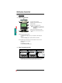
1-2-1
Multifunction Control Unit
•
6
1
2
1) Locking and extraction handle,
2) Built-in LCD screen (2 lines/12 characters),
3) 4-button keypad,
4) Auxiliary control power input 24 V DC,
NOTE: The LUCMT1BL does not provide access
to this input as it is provided for on the
LUTM••BL base.
ENGLISH
3
4
5
5) RJ-45 external communication port, RS 485,
6) Sealing option to prevent removal from the Power
Base.
The built-in keypad and display can enable:
- in Configuration and settings (page 21), local configuration of alarm and protection
functions,
- in "Run" mode (settings) (page 23), selected real time motor load values.
The external RS 485 serial communication port on the front panel can be used to connect to:
- an IBM compatible personal computer,
- a Pocket PC,
- a Programmable Logic Controller.
- door mounted dialog terminal XBT NU 400.
1-2-2
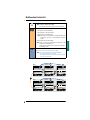
Keypad / programming principles
•
(line 1)
Me n u
(line 2)
Su bMe n u
(line 1)
Su bMe n u
(line 2)
F u n c t i o n
(line 1)
Func t i on
(line 2)
= S e t t i n g
OR
P a r ame t e r
- The Multifunction Control Unit includes a two line display which allows the user to step up/
step down in the Submenu, Function and Setting levels with the four button keypad.
8
Chapter 1 - General information
05-2004
Multifunction Control Unit
•
• Steps up to the previous level in the menu structure.
NOTE: The ESC key does not save a setting.
Successive key strokes may be required to return to the main menu.
•
• Scrolls through the various possibilities
- within a menu ==> the various submenus,
•
- within a submenu ==> The various functions,
- within a function ==> the various settings.
NOTE: Some menu levels only include functions and settings. Others have
functions that can consist of several parameters with different
settings.
NOTE: Default or stored function setting values are indicated by "=" and
available values are indicated by "?".
Holding down the relevant key will accelerate the incrementing /
decrementing of a value.
•
1) Steps down one level in the menu structure,
2) Saves and stores the function settings shown in the display.
NOTE: Once (a function setting) has been saved (with the ENT key):
- the "?" sign will be replaced by the "=" sign,
- the setting remains visible for 2 seconds then automatically steps up
one level in the menu structure.
•
Menu
Function
(line 1)
(line 1)
Con f i gu r e
(line 2)
L a n g u a g e
1
Menu
Function
(line 1)
(line 2)
L o a d T y p e
Language
? F r a n ç a i s
Optional setting
2
LoadType
1
2
(line 2)
(line 1)
Con f i gu r e
05-2004
(line 2)
= En g l i s h
Default setting
Function
(line 1)
Language
Function
Function
2
(line 2)
= 3 PhMo t o r
(=) Default setting
Chapter 1 - General information
Function
(line 1)
2
LoadType
(line 2)
? 1 PhMo t o r
(?) Optional setting
9
ENGLISH
• Scrolls through the function settings available.
Multifunction Control Unit
1-3
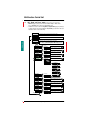
Technical data
1-3-1
Installation
LU•B•
LU•B•
LU•S•
LUTM
C
C
A
B
B
ique
B
ecan
Telem
2
LU9C
2
LU9C
ue
iq
an
c
me
ENGLISH
le
Te
B
CLIC
LU•B•
C
1
C
B
A
TRIP
0
1
RESET
A
2
LU•S•
NOTE: When installed in the Power Base, the Multifunction Control Unit secures the options modules.
The Multifunction Control Unit must be removed for installation or removal of the option
modules.
1-3-2
Operating temperatures
NOTE: The Multifunction Control Units can be
operated at +5° C (9° F) for AC motor loads
less than 12.0 full load Amps on Power Bases
LU•B•• and LU•S•• only,
d
The Multifunction Control Unit has internal
temperature watchdog functions that can not
be disabled.
d
An "Warn-IntTmp" warning will be displayed if
the internal temperature reaches 80°C.
LU•B•• and LU•S••
d = 0 mm (0 in)
45° C (113° F)
d ≥ 9 mm (0.35 in)
55° C (131° F)
d ≥ 20 mm (0.75 in)
60° C (140° F)
The Motor starter will trip and the control unit
will display "Int Trip" if the internal temperature
reaches 90°C.
The internal temperature may be monitored via
the RS485 port :
TM
- locally using the PowerSuite software,
®
- remotely using the Modbus bus.
(see "Fault" mode (diagnostics) (page 25) for
reseting of an "Int Trip" fault).
LUTM••BL
d = 0 mm (0 in)
10
65° C (149° F)
Chapter 1 - General information
05-2004
Multifunction Control Unit
1-3-3
Control connections
1-3-3-1 LUCM••BL
NOTE: Cycling coil control power to the A1, A2 terminals without auxiliary control power will reset all
Off-Faults functions allowing the main contacts to close (see 2-3-4, Warnings and
Faults (diagnostics), page 26).
The coil control input A2 is internally connected to the auxiliary power input (-) terminal.
If the polarity of the A1, A2 terminals has been reversed, the Multifunction Control Unit will trip
on an "Int Trip" 62 fault (see "Fault" mode (diagnostics) (page 25) for reseting of an
"Int Trip" fault).
1-3-3-2 LUCMT1BL
The LUCMT1BL Multifunction Control Unit has only one 24V DC control power input accessible only
by the +/- terminals on the LUTM••BL Power Base. The control power input is required for
configuration and operation.
NOTE: Cycling control power will
Faults (diagnostics), page 26).
reset
all
Off-Faults
(see 2-3-4,
Warnings
and
WARNING
Loss of shutdown protection
• Components that disconnect power, such as E-stop or limit switches, must be connected with the coil
control positive (+) terminal A1.
Failure to follow these instructions can result in death, serious injury, or equipment
damage.
05-2004
Chapter 1 - General information
11
ENGLISH
The LUCM••BL Multifunction Control Unit has two 24V DC power inputs. The coil control input,
accessible only by the A1, A2 terminals on the Power Base, and the auxiliary power input on the face
of the Multifunction Control Unit. The auxiliary power input is only required for the following functions.
- Initial configuration and setting before installation into a Power Base:
- Initial configuration and setting before supplying coil control power to the A1, A2 terminals,
- Operation of remote and auto-reset functions with 3-wire control,
- Modification of settings in the "Off" (see 2-2, p. 21), "Trip" or "Fault" modes (see 2-3-4, p. 26),
- Display of fault type or statistics in the "Trip" and "Off" modes (see 2-3-4, p. 26),
- Communicating with the Multifunction Control Unit in the "Trip" and "Off" modes (see 2-3-4),
- Operation of certain optional communication and function modules.
Multifunction Control Unit
1-3-4
Minimum required setup
See Config Menu (Configuration Menu) Warnings (pages 28 and 29).
The Multifunction Control Unit can be set up quickly by performing the minimum operations below:
- (LUCM••BL) Supply power to the auxiliary power input (24V DC),
or
- (LUCMT1BL) Power the Overload relay/controller LUTM••BL (24V DC)
- Program the Multifunction Control Unit as follows:
ENGLISH
1) Enter the Config Menu (Configuration Menu) (page 27) by pressing the ENT key.
Validate the functions that define the Multifunction Control Unit profile and then enable the
End Config (page 34) function to enter the Main Menu (page 35) or "Pause" mode (see
33_PauseMtr (page 43) for disabling "Pause" mode),
2) In the Main Menu, scroll past 1_Reference (page 35) and 2_Display (page 35) and enter
into the 3_Setup (page 35) submenu,
3) In the 3_Setup submenu, enter into the 31_FLASet (page 41) parameter. Scroll through
and validate the desired full load motor current value.
NOTE: All the other functions and parameters are set to their default values
(see 1-3-5, Default settings and optional values, page 13).
12
Chapter 1 - General information
05-2004
Multifunction Control Unit
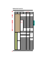
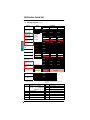
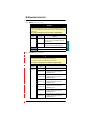
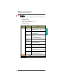
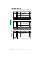
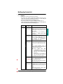
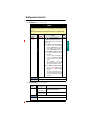
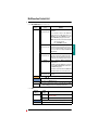
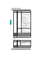
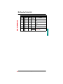
Default settings and optional values
Menu
Submenu
Function
Config Menu ......................
Parameter
Language..................................
Default Setting
Optional values
or Reference
= English
*(for LUCM••BL only)
Main Menu 1_Reference
2_Display
05-2004
? Français
? Español*
? Deutsch*
? Italiano*
LoadType (for LUCM••BL only) ... = 3 PhMotor
? 1 PhMotor
Base (for LUCM••BL only) ...........
? Starter
= SelfProtStr
AuxFan .....................................
= No
? Yes
CT_Ratio
? 30:3
= No
? Yes (3.5 - 10.5 A)
(for LUCMT1BL
only)
? 30:2
= No
? Yes (5.2 - 15.7 A)
(no default,
must be set)
? 30:1
= No
? Yes (10.5 - 31.5 A)
? 50:1
= No
? Yes (17.5 - 52.5 A)
? 100:1
= No
? Yes (35 - 105 A)
? 200:1
= No
? Yes (70 - 210 A)
? 400:1
= No
? Yes (140 - 420 A)
? 800:1
= No
? Yes (280 - 840 A)
? Others
Parameter Submenu
Primary
Secondary
Exter_Pass
1 to 65535
1 to 65000
1 to 65000
End Config................................
= No
? Yes
11_Catalog ...............................
LUCMx6BL
(see 31_FLASet)
12_Firmware.............................
Rev: xx.xx
13_FLA Range .........................
0.15 A to 0.6 A
(Min to Max)
(see 31_FLASet)
14_LoadType............................
= 3 PhMotor
15_AuxFan ...............................
= No
Determined by
Multifunction
Control Unit
(reference)
(read only)
Set in Config
Menu (page 27)
16_PowerBase .........................
= SelfProtStr
21_AvCurrent ..........................
= Yes
? No
22_ThermCap...........................
= No
? Yes
23_L1Current ...........................
= No
? Yes
? Yes
24_L2Current ...........................
= No
25_L3Current ...........................
= No
? Yes
26_GFCurrent ..........................
= No
? Yes
27_LastTrip...............................
= No
? Yes
28_PhaseImb ...........................
= No
? Yes
29_ONhours .............................
= No
? Yes
Chapter 1 - General information
13
ENGLISH
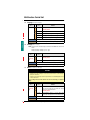
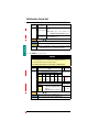
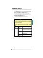
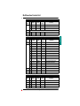
1-3-5
Multifunction Control Unit
Menu
Submenu
(Main Menu) 3_Setup
Function
Parameter
31_FLASet
*LUCMx6BL
*(for LUCM••BL *LUCM1xBL
only)
*LUCM05BL
Determined by
Multifunction *LUCM12BL
Control Unit *LUCM18BL
(reference)
*LUCM32BL
(1 among the 6)
ENGLISH
(for LUCMT1BL
only)
LUCMT1BL
Default Setting
Optional values
or Reference
= 0.15 A
? 0.15 to 0.6
= 0.35 A
? 0.35 to 1.4
= 1.25 A
? 1.25 to 5
=3A
? 3 to 12
= 4.5 A
? 4.5 to 18
=8A
? 8 to 32
= 0.35 A
? 0.35 to 1.05
(% CT_Ratio)
(% CT_Ratio)
32_TestTrip ..............................
= No
? Yes
33_PauseMtr ............................
= No
? Yes
34_Language............................
= English
? Français
? Español*
? Deutsch*
? Italiano*
35_PauseMode ........................
= Yes
? No
41_TripClass ............................
=5
? 5 to 30
42_ResetMode .........................
= Manual
? Remote/Ent
? Auto
43_RstAdjust
ResetTime
= 120 Sec.
? 1 to 1000
ResetLevel
= 80%
? 35 to 95
*(for LUCM••BL only)
4_AdvSetup
(Capacity)
44_MagTrip (for LUCM••BL only) = 1420% FLA
? 300 to 1700
45_OLWarning Warning
= On
? Off
= 85%
? 10 to 100
Warn Level
(Capacity)
46_GroundFlt
47_PhaseImb
14
Trip
= On
? Off
TripTime
= 1.0 Sec.
? 0.1 to 1.2
TripLevel
=xA
(30% FLA min)
? 20 to 500
Warning
= On
? Off
Warn Level
=xA
(30% FLA min)
? 20 to 500
Trip
= On
? Off
TripTimeStrt
= 0.7 Sec.
? 0.2 to 20
TripTimeRun
= 5.0 Sec.
? 0.2 to 20
TripLevel
= 10% IMB
? 10 to 30
Warning
= On
? Off
Warn Level
= 10% IMB
? 10 to 30
Chapter 1 - General information
05-2004
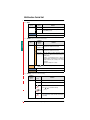
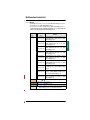
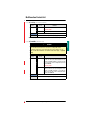
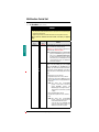
Multifunction Control Unit
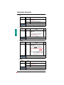
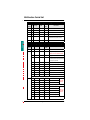
Submenu
(Main Menu) (4_AdvSetup)
Function
48_Jam
Parameter
Trip
= Off
? On
TripTime
= 5 Sec.
? 1 to 30
TripLevel
= 200% FLA
? 100 to 800
Warning
= Off
? On
Warn Level
= 200% FLA
? 100 to 800
Trip
= Off
? On
TripTime
= 10 Sec.
? 1 to 200
TripLevel
= 50% FLA
? 30 to 100
Warning
= Off
? On
Warn Level
= 50% FLA
? 30 to 100
Trip
= Off
? On
TripTime
= 10 Sec.
? 1 to 200
TripLevel
= 100% FLA
? 100 to 800
Warning
= Off
? On
Warn Level
= 100% FLA
? 100 to 800
=1
? 1 to 247
= 19200 bps
? 1200 to 19200
53_Parity ..................................
= None
? Even
54_Control ................................
= On
? Off
55_CommLoss .........................
= Ignore
? Dropout
? Trip
? Warning
61_ID Clear ..............................
= Yes
= No
62_Reference
49_UnderLoad
410_LongStrt
5_CommSetup 51_Drop....................................
52_Baud ...................................
6_Module
Default Setting
Optional values
or Reference
Module
ID = 0
Catalog
?
Firmware
Rev: 0.00
ENGLISH
Menu
(if ID = 0)
(if ID = 0)
63_Id Set ..................................
7_Statistics
=0
0 to 149
64_Param dec
Parameter 1-16 = 00000
00000 to 65535
65_Param hex
Parameter 1-16 = 0000
0000 to FFFF
71_Trip0 ...................................
72_Trip1 ...................................
73_Trip2 ...................................
74_Trip3 ...................................
75_Trip4 ...................................
Statistics data
is cleared
by default
(see 7_Statistics, page 73)
76_Totals .................................
05-2004
Chapter 1 - General information
15
Multifunction Control Unit
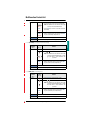
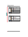
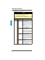
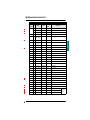
Menu
Submenu
Parameter
81_Unlock ................................
Default Setting
Optional values
or Reference
Passwd?
0000 - 9999
82_Lock ...................................
NewPSW?
0000 - 9999
83_Rst Stats ............................
= No
? Yes
84_RstToDfts............................
= No
? Yes
ENGLISH
(Main Menu) 8_Password
Function
16
Chapter 1 - General information
05-2004
Multifunction Control Unit
1-3-6
Specifications
1-3-6-1
Environment
IEC 947-4-1, IEC 34-11, IEC 755, VDE 0106, VDE 0660
European community
directives
marking. Meets the essential requirements of low Voltage equipment
(LV) & Electromagnetic Compatibility (EMC)
Approvals
UL 508, CSA, PTB
Protective treatment
"TH" (Tropical Finish)
Degree of protection
Conforming to IEC 947-1
IP 20(1)
Pollution degree
Conforming to IEC 664
3
Shock resistance
Conforming to IEC 68-2-27
10g open, 15g closed, 11
milliseconds
Vibration resistance
Conforming to IEC 68-2-6
Ambient air temperature
around the device
Storage
Operation
Flame resistance
2g open, 4g closed, 5 to 150 Hz
°C
°F
- 35 to + 85
- 31 to + 185
°C -20 to +60 (see 1-3-2, Operating
°F -4 to +140 temperatures, page 10 for
derating considerations)
Conforming to UL 94
V2
m
ft
Maximum operating altitude
2000
6562
Operating position
In relation to normal
vertical mounting plane
Electromagnetic compatibility
Electrostatic discharge
Conforming to IEC 1000-4-2
level 3
kV
8
Electromagnetic compatibility
Electromagnetic field
Conforming to IEC 1000-4-3
level 3
V/m
10
Electromagnetic compatibility
Fast transient burst
Conforming to IEC 1000-4-4
level 4
kV
4
Horizontal or vertical 30° angle
front or back
Common mode
Conforming to IEC 1000-4-5
Electromagnetic compatibility
Surge immunity
ENGLISH
Conforming to standards
Serial mode
Level 4 (Power circuit)
kV
6
4
Level 1 (Control circuit)
kV
1
0.5
Level 2 (Communication circuit)
kV
1
1
Electromagnetic compatibility
Conducted disturbances
Conforming to IEC 1000-4-6
level 3
V
Rated undissipated pulse
withstand (U imp)
Conforming to IEC 947-1
kV
3(2)
10(3)
2
Resistance to low frequency
Conforming to IEC 947-2
disturbances - supply harmonics Appendix F Clause F4.1
Resistance to micro-breaks
Conforming to IEC 1000-4-11
(1) Only applicable when power cabling to Power Base exceeds the following sizes: 1,5 mm 2 (16 AWG)
fitted with cable end or 2.5 mm2 (14 AWG) not fitted with cable end.
(2) Conforms to IEC 1000-4-6 when 46_GroundFlt + TripLevel is set < 50% FLA minimum.
(3) Conforms to IEC 1000-4-6 when 46_GroundFlt + TripLevel is set > 50% FLA minimum
05-2004
Chapter 1 - General information
17
Multifunction Control Unit
1-3-6-2
Power circuit
V
110 to 690 VAC
V
690 VAC
Operating frequency(4)
Hz
47-63
Rated operational current
A
Operating voltage range
ENGLISH
Rated insulation voltage
(Ui)
Conforming to IEC 947-1
LUCMx6BL
...........................................
0.15 to 0.6
LUCM1xBL
...........................................
0.35 to 1.4
LUCM05BL
...........................................
1.25 to 5
LUCM12BL
...........................................
3 to 12
LUCM18BL
...........................................
4.5 to 18
LUCM32BL
...........................................
8 to 32
(4) For use with 110 to 690 V, 50/60 Hz AC motors only. Not approved for use with DC motors.
- Approved for use upstream of variable frequency drives.
- Not approved for use downstream of variable frequency drives
1-3-6-3
Control circuit supply (A1, A2 terminals and auxiliary power input)
Operating voltage
20.4 to 31.2 VDC
Rated insulation voltage (Ui)
Conforming to IEC 947-1
V
380 VAC
Cabling (aux. power only)
- Solid or stranded cable ..........
1 conductor
mm2
AWG
0.5 to 1
20 to 18
- Stranded cable
with cable end .......................
1 conductor
mm2
AWG
0.5 to 1
20 to 18
- Solid cable ............................
2 conductors
mm2
AWG
0.2 to 1
24 to 18
- Stranded cable ......................
2 conductors
mm2
AWG
0.2 to 1.5
20 to 18
Terminal tightening torque (aux.
power only)
18
V
Chapter 1 - General information
N.m 0.5 to 0.6
lb-in 4.6 to 5.6
05-2004
Multifunction Control Unit
1-3-6-4
RS 485 Serial port RJ-45 connector
Electrical Interface
RS 485
Connector
RJ-45
•
RJ-45 pin-out
(cable connector top view)
D(A)
D(B)
+5V
common
5
1
4
7
8
8
V
Max. line length
m (ft) 1000 m (3280 ft)
max. tap-off length
m (ft) 20 m (65 ft)
Parity
None - 1 start bit, 8 data bits and 1 stop bit (10 bits total Default)
ENGLISH
1 kV
Isolation
Even - 1 start bit, 8 data bits, even parity and 1 stop bit (11 bits total)
Modbus® RTU commands The Multifunction Control Units shall support the following Modbus® RTU
commands:
- Code 3 (03 hex) - Normal read holding registers (maximum 100 registers)
- Code 6 (06 hex) - Preset (write) single register
- Code 16 (10 hex) - Preset (write) multiple registers (maximum count = 46)
- Code 65 (41 hex) - Private identification request (specific for drives)
The Multifunction Control Units shall support the following Modbus® RTU
reponses:
- Code 3 (03 hex) - Normal read holding registers reponse
- Code 6 (06 hex) - Normal preset (write) single register reponse
- Code 16 (10 hex) - Normal preset (write) multiple registers reponse
- Code 65 (41 hex) - Private identification reponse
(data specific for drives: { 0x01, ’-’, 0x01, ’-’, ’B’, ’2’, ’B’, ’2’, ’B’, ’2’, ’B’, ’2’, ’B’,
’2’, ’X’, ’w’, 0x28, 0x01, 0x00} )
The Multifunction Control Units shall support the following Modbus® RTU
codes:
- Code 01 - Illegal function
- Code 02 - Illegal data address
- Code 03 - Illegal data value (write command not completed)
The 54_Control (Write Control) (page 67) enable feature can be used to
enable (On) or disable (Off) write privilege to the Multifunction Control
Units configuration registers. If 54_Control (Write Control) (page 67) is
(No), write commands are restricted to the following list of " - always
enabled - " registers:
- Remote keypad (register 1100)
- Multifunction Control Units state control (register 704)
- Multifunction Control Units extended state control (register 705)
- Option module configuration (registers 680-690)
- Private registers above 20000
05-2004
Chapter 2 - Operation
19
Multifunction Control Unit
Chapter 2 - Operation
2-1
Menu structure
• Config Menu (Configuration Menu) (page 27) contains equipment specific settings not
considered adjustable after initial configuration.
• Main Menu (page 35) contains application specific settings and parameters considered adjustable.
Config
First
power-up
(see 2-2-1, p. 21)
ENGLISH
Config Menu
Language
Language
= English
Config Menu
LoadType
(for LUCM••BL only)
Config Menu
PowerBase
(for LUCM••BL only)
Config Menu
AuxFan
Config Menu
CT_Ratio
Config Menu
EndConfig
LoadType
= 3 Ph Motor
PowerBase
= SelfProtStr
AuxFan
= No
(for LUCMT1BL only)
CT_Ratio
= 30:3
EndConfig
= No
? Yes
Allows selection of
display languages.
Allows selection of single or
3-phase motor protection.
Allows selection of
power base type used.
Allows selection of thermal
protection for fan cooled motors.
Allows selection of the correct
current transformer used.
Allows user to exit
"Config" menu.
(==> 84_RstToDfts)
Main Menu
1_Reference
OFF
or
Main Menu
2_Display
or
Main Menu
3_Setup
or
Main Menu
4_AdvSetup
Ready
Pause
Run
Subsequent
power-ups
(see 2-2-2, p. 22)
Main Menu
5_CommSetup
Main Menu
6_Module
Main Menu
7_Statistics
Main Menu
8_Password
20
Chapter 2 - Operation
1_Reference
11_Catalog
2_Display
21_AvCurrent
3_Setup
31_FLASet
4_AdvSetup
41_Trip Class
5_CommSetup
51_Drop
6_Module
61_ID Clear
7_Statistics
71_Trip0
8_Password
81_Unlock
--84_RstToDfts
Contains product references
“Config” settings.
Allows selection of items
displayed during "Run" mode.
Contains basic settings
accessible during "Run" mode.
Contains advanced settings
accessible during "Off" mode.
Contains settings for RS-485
Modbus© communication port.
Allows configuration of
optional modules.
Contains stored "Fault" and
"Run" informations.
Allows password enabling and
module resets for
settings and statistics.
84_RstToDfts
= No
? Yes
05-2004
Multifunction Control Unit
2-2
Configuration and settings
2-2-1
"Config" mode
(first power-up: configuration and settings)
• The Multifunction Control Unit must be configured before it will allow the power contacts to be closed.
• Configuration can be made on the LUCM••BL by suppling 24V DC to either the auxiliary control
terminals or to coil control A1, A2 terminals on the LU•B•• and LU•S•• Power Base,
• Configuration can be made on the LUCMT1BL by suppling 24V DC to the +/- control power input
on the LUTM••BL Power Base,
• The LUCMT1BL and, when using only coil control power to the LUTM••BL Power Base A1, A2
terminals the Multifunction Control Unit goes into the "Pause" mode when End Config (page 27)
is validated. The power contacts can be closed by disabling the 33_PauseMtr (page 41) function
(see warning, 33_PauseMtr (Software Motor Stop), page 43).
• The LUCMT1BL Multifunction Control Unit has no default setting for the CT_Ratio configuration.
The CT_Ratio must be set before proceeding to End Config (page 27).
Config Menu
Language
....
....
Language
= English
....
....
Config Menu
EndConfig
EndConfig
= No
? Yes
(==> 84_RstToDfts)
Main Menu
1_Reference
....
1_Reference
11_Catalog
....
Main Menu
4_AdvSetup
ENGLISH
Config
LUCMT1BL
"Pause" mode
(see 33_PauseMtr
(Software Motor
Stop) (page 43) for
disabling "Pause"
mode).
(see 2-5, Main Menu, page 35)
(read and write)
4_AdvSetup
41_Trip Class
4_AdvSetup
45_OLWarning
45_OLWarning
Warning
45_OLWarning
Warn Level
Warn Level
= 85 %
Warn Level
Main Menu
4_AdvSetup
....
4_AdvSetup
45_OLWarning
? 92 %
Warn Level
= 92 %
....
Main Menu
8_Password
05-2004
(read and write)
8_Password
81_Unlock
--84_RstToDfts
Chapter 2 - Operation
84_RstToDfts
= No
? Yes
21
Multifunction Control Unit
2-2-2
"Off", "Ready" and "Pause" modes (subsequent power-ups and settings)
• Main Menu (page 35) settings can be modified in the "Off", "Ready" or "Pause" modes.
See , 33_PauseMtr (page 41) function for enabling "Pause" mode.
• Should it be necessary to re-enter the Config Menu (Configuration Menu) (page 27) and change
a configure setting, the user must first validade the 84_RstToDfts (page 77) function. This resets
all parameters back to factory default settings.
Off
=>
Indicates main contacts are open and no power detected at A1, A2 terminals.
=>
Indicates main contacts are closed with less than 10% of the set FLA current is detected.
or
Ready
or
Pause
Indicates main contacts are open with power detected at A1, A2 terminals.
=>
ENGLISH
(see warning, 33_PauseMtr (Software Motor Stop), page 43)
Main Menu
1_Reference
(read only)
Main Menu
2_Display
(read and write)
Main Menu
3_Setup
(read and write)
Main Menu
4_AdvSetup
(read and write)
1_Reference
11_Catalog
2_Display
21_AvCurrent
3_Setup
31_FLASet
4_AdvSetup
41_Trip Class
4_AdvSetup
45_OLWarning
During "Off", "Ready" + "Pause" modes
"1_Reference" parameters are read only
During "Off", "Ready" + "Pause" modes
"2_Display" parameters are read and write
During "Off", "Ready" + "Pause" modes
"3_Setup" parameters are read and write
During "Off", "Ready" + "Pause" modes
"4_AdvSetup" parameters are read and write
45_OLWarning
Warning
45_OLWarning
Warn Level
Warn Level
= 85 %
Warn Level
Main Menu
4_AdvSetup
(read and write)
Main Menu
5_CommSetup
(read and write)
Main Menu
6_Module
(read and write)
Main Menu
7_Statistics
(read only)
Main Menu
8_Password
(read and write)
If key is not touched
22
4_AdvSetup
45_OLWarning
5_CommSetup
51_Drop
6_Module
61_Reference
7_Statistics
71_Trip0
for
30 sec.
8_Password
81_Unlock
Chapter 2 - Operation
? 92 %
Warn Level
= 92 %
During "Off", "Ready" + "Pause" modes
"5_CommSetup" parameters are read and write
During "Off", "Ready" + "Pause" modes
"6_Module" parameters are read and write
During "Off", "Ready" + "Pause" modes
"7_Statistics" parameters are read only
During "Off", "Ready" + "Pause" modes
"8_Password" parameters are read and write
05-2004
Multifunction Control Unit
2-2-3
"Run" mode (settings)
• Line 1 of the display shows "Run" when the Power Base main contacts are closed and more than
10% of the set FLA current is detected.
• Line 2 of the display can be set to scroll certain information for monitoring
(see 2-5-2, 2_Display, page 37).
• Only functions 2_Display (page 37) and 3_Setup (page 41) can be modified when the
Multifunction Control Unit is in the "Run" mode.
Run
IAV=2.5A
Run
Therm=65%
Run
IL1=2.5A
(22_ThermCap = Thermal
capacity)
(23_L1Current = Phase 1
current)
(21_AvCurrent = Average
3 phase current)
(24_L2Current = Phase 2
current)
Scrolling Run info
display
Run
IL3=3.5A
(if more than one item selected)
Run
ONhours=52
(29_ONhours = Total
hours of Run time)
Run
IL2=3.5A
ENGLISH
Power-up
(25_L3Current = Phase 3
current)
Run
Imbal=1.0A
Run
LT : Over-Load
(28_PhaseImb = Phase
imbalance)
Main Menu
1_Reference
(read only)
Main Menu
2_Display
(read and write)
Main Menu
3_Setup
(read and write)
(27_LastTrip = Last trip
type)
1_Reference
11_Catalog
2_Display
21_AvCurrent
3_Setup
31_FLASet
Run
IGR=0.2A
(26_GFCurrent = Ground
fault current)
During "Run" mode
"1_Reference" parameters are read only
During "Run" mode
"2_Display" parameters are read and write
During "Run" mode
"3_Setup" parameters are read and write
31_FLASet
= 2.5A
31_FLASet
? 2.9A
Main Menu
3_Setup
(read and write)
Main Menu
4_AdvSetup
(read only)
Main Menu
5_CommSetup
(read only)
Main Menu
6_Module
(read only)
Main Menu
7_Statistics
(read only)
Main Menu
8_Password
(read only)
If key is not touched
05-2004
3_Setup
31_FLASet
4_AdvSetup
41_Trip Class
5_CommSetup
51_Drop
6_Module
61_Reference
7_Statistics
71_Trip0
for
30 sec.
8_Password
81_Unlock
Chapter 2 - Operation
after
2 sec.
31_FLASet
= 2.9A
During "Run" mode
"4_AdvSetup" parameters are read only
During "Run" mode
"5_CommSetup" parameters are read only
During "Run" mode
"6_Module" parameters are read only
During "Run" mode
"7_Statistics" parameters are read only
During "Run" mode
"8_Password" parameters are read only
23
Multifunction Control Unit
2-3
Monitoring the motor
2-3-1
"Run" mode (monitoring)
• When the main power contacts are closed and more than 10% of the set FLA current is detected,
line 1 of the display will show "Start" indicating the Multifunction Control Unit is waiting for the motor
to complete it’s start cycle.
• When the "Start" cycle has ended, the display will show "Run" indicating the "Run"
mode (monitoring). The user can then compare actual "Run" values with protection settings and
make adjustments as necessary (see 2-2-3, "Run" mode (settings), page 23).
RunStart
IAV=2.5A
or
or
some
seconds later
some
seconds later
ENGLISH
Second
Scrolling
Second
Scrolling
line
Scrolling
line
Scrolling
Run
IAV=2.5A
Average 3 phase current
(2_Display/21_AvCurrent)
Display = Yes by default
Main Menu
1_Reference
Thermal capacity
(2_Display/22_ThermCap)
Display = No by default
....
If key is not touched
2-3-2
(see 2-5-2, 2_Display, page 37)
1_Reference
11_Catalog
....
Ground fault current
(2_Display/26_GFCurrent)
Display = No by default
for
30 sec.
(see 2-2-3, "Run"
mode (settings), page 23)
"Warning" mode (diagnostics)
• When an enabled warning occurs, line 1 of the display will show "Warn" followed by the warning
type (see 2-3-4, Warnings and Faults (diagnostics), page 26).
• By pressing ENT when a warning is displayed, the user may scrole through the settings and verify
the set Warn Level. Adjustment of the Warn Level is done in "Off" mode (see 2-2, p. 21).
RunStart
IAV=2.5A
or
or
some
seconds later
some
seconds later
Second
Scrolling
Example:
Second
Scrolling
Scrolling
line
Warn - OL
IAV=2.5A
Average 3 phase current
(2_Display/21_AvCurrent)
Display = Yes by default
Main Menu
1_Reference
....
Thermal capacity
(2_Display/22_ThermCap)
Display = No by default
Line 1: Warning message (OL,
GF, Imbal, Jam, LS,
UL, Input 1, IntTemp)
Line 2: Parameter(s) selected
to be displayed
1_Reference
11_Catalog
some
seconds later
....
If key is not touched
24
Scrolling
line
Chapter 2 - Operation
for
30 sec.
Ex: Tripped
Over_load
Fault
message
05-2004
Multifunction Control Unit
2-3-3
"Fault" mode (diagnostics)
• Detected faults will either trip the base mechanism or open the power contacts depending on the
fault type (see 2-3-4, Warnings and Faults (diagnostics), page 26) and reset mode selected
(see , 42_ResetMode, page 48).
• Faults that trip the base mechanism will show "Tripped" in the line 1 of the display and the fault
type in the line 2. A Manual Reset will be required before a restart can be made.
• Faults that open the power contacts will show "Off-Fault Type" in line 1 of the display and
"Ent to Reset" in line 2. Reset can be made by pressing the ENT key or sending a remote reset
signal via the RS 485 communication port or by an optional module. "Over_load" and "Test Trip"
faults will show "Wait" and the delay in seconds before "Ent to Reset" appears.
Start
IAV=3.0A
or
If the "Warning"
is disabled
Run
IAV=2.5A
Tripped
Over_load
Main Menu
1_Reference
....
....
Main Menu
7_Statistics
Warn - . . .
IAV=2.5A
If the "Warning"
is disabled
some
seconds later
Example:
or
ENGLISH
NOTE: On the LUCM••BL, resetting "Off-" faults will automatically start the motor if coil control
power is still applied to A1, A2 terminals.
Tripped fault types can not be displayed without auxiliary control power to the LUCM••BL.
some
seconds later
some
seconds later
(see 2-3-4, Warnings and
Faults (diagnostics), page 26)
Fault message
(read only)
1_Reference
11_Catalog
During "Run" mode
"1_Reference" parameters are read only
....
....
(read only)
7_Statistics
71_Trip0
If key is not touched
During "Run" mode
"7_Statistics" parameters are read only
for
30 sec.
(see 2-5-7, 7_Statistics, page 73)
• Faults that show "Int Trip" in line 1 of the display and Fault type code in line 2, indicate internal
Faults detected by the Multifunction Control Unit. A Manual Reset and cycling of the auxilliary
control power from On to Off will be required before a Restart can be made.
05-2004
Chapter 2 - Operation
25
Multifunction Control Unit
Warnings and Faults (diagnostics)
2-3-4
Warning or
Fault Type
Warning
message
"Manual" Mode
Warn-OL
"Auto" Mode
Tripped
Over_Load
Off-OL
Wait xxx (Secs)
Off-OL
Auto xxx (Secs)
Tripped
Short
Tripped
Short
Tripped
Short
Tripped
Shunt
Tripped
Shunt
Tripped
Shunt
Tripped
MagTrip
Tripped
MagTrip
Tripped
MagTrip
Tripped
Ground Fault
Tripped
Ground Fault
Tripped
Ground Fault
Tripped
PhasImb
Off-Imbal
Ent to Reset
Off-Imbal
Ent to Reset
Tripped
Jam
Off-Jam
Ent to Reset
Off-Jam
Ent to Reset
Tripped
LngStrt
Off-LongSt
Ent to Reset
Off-LongSt
Ent to Reset
Tripped
UnderLoad
Off-UndrLd
Ent to Reset
Off-UndrLd
Ent to Reset
Test Trip Fault
Tripped
TestTrp
Off-Test
Wait xxx (Secs)
Off-Test
Auto xxx (Secs)
Internal Fault
(see list below fault type)
Int Trip
xx
Int Trip
xx
Int Trip
xx
Int Trip
51
Int Trip
51
Int Trip
51
Thermal Overload
(scrolled Run info)
Short circuit Fault
(LUCM••BL only)
Line 1
Line 2
These faults
will reset
automaticaly
in the
LUCMT1BL
Shunt trip Fault
(LUCM••BL only)
Magnetic Fault
(LUCM••BL only)
ENGLISH
Fault Message
"Remote/Ent" Mode
Warn-GF
Ground Fault
(scrolled Run info)
Warn-Imbal
Phase Imbalance
Fault
(scrolled Run info)
Warn-Jam
Jam Fault
(scrolled Run info)
Warn-LongSt
Long Start Fault
(scrolled Run info)
Warn-UndrLd
Under Load Fault
(scrolled Run info)
Internal temperature
Fault
Warn-Int Temp
(scrolled Run info)
Type
Warning Mode
Trip Mode
Dropout Mode
Lost Communications
Fault
Warn-Comm
(scrolled Run info)
Tripped
CommLoss
Off-Comm
Ent to Reset
Option Module Fault
Warn-Mxxx
(scrolled Run info)
Tripped
Mxxx
Off-Mxxx
Ent to Reset
*
*
See option module instruction
material for fault codes.
Fault Code
51
Mxxx : indicates Warning, Dropout or Fault code.
See option module instruction manual for Fault code
identification.
Internal Fault Type
Fault Code
Multifunction Control Unit Internal
Temperature
(see 1-3-2, Operating
temperatures, page 10)
26
Internal Fault Type
57
ROM (flash) check
58
Hardware Watchdog
59
Current detected while OFF
(L2 current) detected in 1-Phase Mode
52
Asic read-after-write
60
53
Asic initialize check
61
Base trip not detected
54
Coil control and Asic watchdog
62
Control wiring fault
55
Stack Overflow check
63
Control overvoltage
56
RAM check
"EEROM Error" EE Prom checksum
Chapter 2 - Operation
05-2004
Multifunction Control Unit
2-4
Config Menu (Configuration Menu)
• The Config Menu (Configuration Menu) is the initial menu displayed by the Multifunction Control
Unit as shipped from the factory.
• It contains the configuration settings that are equipment specific. These settings are not typically
adjusted after initial configuration.
• To exit the Config Menu (Configuration Menu), you must save the End Config function.
• To access the Config Menu (Configuration Menu) after the End Config is saved, the
Multifunction Control Unit must be reset to default factory settings (see 84_RstToDfts, page 77).
• These settings are always viewable in the 1_Reference (page 35) menu.
• The CT_Ratio function in the LUCMT1BL must be set before accessing the End Config function.
Config Menu
Function
(line 2)
Definition
Language
Selects the language used in the Multifunction Control Unit
(see 2-4-1, p. 28) display.
NOTE: Language type can also be selected in
34_Language (page 42).
LoadType
Sets motor protection functions for 3-phase or 1-phase.
(see 2-4-2, p. 28) NOTE: Selecting the 1-phase setting with 3-phase motors
will cause an internal trip 60 indicating
(for LUCM••BL
24_L2Current detected in 1-phase mode.
only)
(see CAUTION, page 28)
Base
(see 2-4-3, p. 28) Identifies the type of Power Base in which the Multifunction
Control Unit will be installed. The Power Base type is
(for LUCM••BL
marked on the side of the base device.
only)
NOTE: This function serves as an identifier only. It does
not influence the protection functions, settings or
type of protection that the Power Base provides.
(see CAUTION, page 29)
AuxFan
(see 2-4-4, p. 29) Sets thermal protection settings for motors cooled by
auxiliary fans.
NOTE: When enabled, effective thermal reset time is
reduced by a factor of 4. For reset times,
See Appendix A - Thermal Trip and Reset
curves (page 81).
(see CAUTION, page 29)
CT_Ratio
(see 2-4-5, p. 29) Sets current scale in Amperes for protection settings and
display values. The CT_Ratio is set for the current
(for LUCMT1BL
transformers sellected for the application.
only)
NOTE: CT_Ratio must be set before enabling the
End Config (page 34) function.
Sets initial configuration and enables the Main Menu
End Config
(see 2-4-6, p. 34) (page 35).
NOTE: Once End Config (page 34) is saved, the
Config Menu (Configuration Menu) is accessed
by resetting the device back to factory default
settings (see 84_RstToDfts, page 77).
NOTE: Press
or
to enable stepping through all the display functions.
ENT : Sends to functions settings.
05-2004
Chapter 2 - Operation
27
ENGLISH
Menu
(line 1)
Multifunction Control Unit
2-4-1
Language (Unit Display Language)
Function
(line 1)
Language
Setting
(line 2)
Definition
= English
Sets display to English.
Enabled by default.
? Français
Sets display to French.
? Español
Sets display to Spanish (for LUCM••BL only).
? Deutsch
Sets display to German (for LUCM••BL only).
? Italiano
Sets display to Italian (for LUCM••BL only).
ENT : Saves setting and returns to Config Menu (page 27).
ENGLISH
ESC : Does not save a setting, returns to Config Menu (page 27).
2-4-2
LoadType (Motor Load Type)
NOTE: Load Type sets the calculated average current value in the Multifunction Control Unit as
follows:
3-Phase Load setting - I Average = (I1 + I2 + I3) / 3
1-Phase Load setting - I Average = (I1 + I2 + I3) / 2
Function
(line 1)
Setting
(line 2)
Definition
LoadType
= 3 PhMotor
(for LUCM••BL
only)
Sets unit configuration to three phase motor protection.
Enabled by default.
? 1 PhMotor
Sets unit configuration for single phase motor protection.
ENT : Saves setting and returns to Config Menu (page 27).
ESC : Does not save a setting, returns to Config Menu (page 27)
2-4-3
Base (Motor Starter Power Base Type)
CAUTION
Incorrect Power Base setting
• Changing the Power Base setting does not affect motor protection functions or current interruption
capacity of the Power Base,
• Setting incorrect Power Base may cause the wrong Power Base to be read and displayed by the LCD
or remote network device.
Incorrect setting of the Power Base function can result in serious injury, or equipment
damage.
Function
(line 1)
Base
Setting
(line 2)
Definition
= SelfProtStr
Sets identification reference for a self-protected motor
starter, which provides both short circuit and overload
protection for a motor branch circuit.
Enabled by default.
? Starter
Sets identification reference for a motor starter, which
provides only overload protection for a motor branch circuit.
(for LUCM••BL
only)
ENT : Saves setting and returns to Config Menu (page 27).
ESC : Does not save a setting, returns to Config Menu (page 27)
28
Chapter 2 - Operation
05-2004
Multifunction Control Unit
2-4-4
AuxFan (Auxiliary Fan Cooled Motor)
CAUTION
Incorrect AuxFan setting
• When the AuxFan option is set, the reset (motor cool down) time is reduced by a factor of 4,
• If the motor is not equipped with an operating auxiliary cooling fan, the calculated thermal capacity
will be incorrect.
Incorrect setting of the AuxFan function can result in injury, or equipment damage.
AuxFan
Setting
(line 2)
Definition
= No
Disables Auxiliary Fan Cooled function setting thermal
protection levels for motors not cooled by auxiliary fans.
Disabled by default.
? Yes
Enables Auxiliary Fan Cooled function setting thermal
protection levels for motors cooled by auxiliary fans.
ENT : Saves setting and returns to Config Menu (page 27).
ESC : Does not save a setting, returns to Config Menu (page 27).
2-4-5
CT_Ratio (Current Transformer Ratio)
CAUTION
Incorrect CT_Ratio setting
• The CT_Ratio must be set to match the current transformer being used,
• CT_Ratio sets default values for FLA and other motor protection functions.
Incorrect setting of CT_Ratio function can result in injury, or equipment damage.
Function
(line 1)
CT_Ratio
(for LUCMT1BL
only)
Parameter
(line 2)
•••
Definition
No default value ==> must be set.
? 30:3
Sets FLA current scale for current transformers with a
(see 2-4-5-1, p. 30) 30:3 (primary current/secondary current) ratio.
(see 31_FLASet, page 41)
Sets FLA current scale for current transformers with a
? 30:2
(see 2-4-5-2, p. 30) 30:2 (primary current/secondary current) ratio.
(see 31_FLASet, page 41)
Sets FLA current scale for current transformers with a
? 30:1
(see 2-4-5-3, p. 30) 30:1 (primary current/secondary current) ratio.
(see 31_FLASet, page 41)
Sets FLA current scale for current transformers with a
? 50:1
(see 2-4-5-4, p. 31) 50:1 (primary current/secondary current) ratio.
(see 31_FLASet, page 41)
Sets FLA current scale for current transformers with a
? 100:1
(see 2-4-5-5, p. 31) 100:1 (primary current/secondary current) ratio.
(see 31_FLASet, page 41)
Sets FLA current scale for current transformers with a
? 200:1
(see 2-4-5-6, p. 31) 200:1 (primary current/secondary current) ratio.
(see 31_FLASet, page 41)
05-2004
Chapter 2 - Operation
29
ENGLISH
Function
(line 1)
Multifunction Control Unit
(CT_Ratio)
(for LUCM••BL
only)
? 400:1
Sets FLA current scale for current transformers with a
(see 2-4-5-7, p. 31) 400:1 (primary current/secondary current) ratio.
(see 31_FLASet, page 41)
Sets FLA current scale for current transformers with a
? 800:1
(see 2-4-5-8, p. 32) 800:1 (primary current/secondary current) ratio.
(see 31_FLASet, page 41)
Sets FLA current scale for current transformers ratios
? Others
(see 2-4-5-9, p. 32) not shown above.
(see 31_FLASet, page 41)
NOTE: Press
or
to enable stepping through all the CT_Ratio parameters.
ENT : Sends to parameters settings.
ENGLISH
ESC : Does not save a setting, returns to Config Menu (page 27).
2-4-5-1
30:3
Parameter
(line 1)
? 30:3
Setting
(line 2)
Definition
= No
Returns to CT_Ratio parameter selection (page 27)
? Yes
Sets CT_Ratio to 30:3. Sets FLASet range to 3.5 - 10.5 Amps
(see 31_FLASet, page 42).
ENT : Saves setting and returns to CT_Ratio (page 29).
ESC : Does not save a setting, returns to CT_Ratio (page 29).
2-4-5-2
30:2
Parameter
(line 1)
? 30:2
Setting
(line 2)
Definition
= No
Returns to CT_Ratio parameter selection (page 27)
? Yes
Sets CT_Ratio to 30:2. Sets FLASet range to 5.2 - 15.7 Amps
(see 31_FLASet, page 42).
ENT : Saves setting and returns to CT_Ratio (page 29).
ESC : Does not save a setting, returns to CT_Ratio (page 29).
2-4-5-3
30:1
Parameter
(line 1)
? 30:1
Setting
(line 2)
Definition
= No
Returns to CT_Ratio parameter selection (page 27)
? Yes
Sets CT_Ratio to 30:1. Sets FLASet range to 10.5 - 31.5 Amps
(see 31_FLASet, page 42).
ENT : Saves setting and returns to CT_Ratio (page 29).
ESC : Does not save a setting, returns to CT_Ratio (page 29).
30
Chapter 2 - Operation
05-2004
Multifunction Control Unit
2-4-5-4
50:1
Parameter
(line 1)
? 50:1
Setting
(line 2)
Definition
= No
Returns to CT_Ratio parameter selection (page 27)
? Yes
Sets CT_Ratio to 50:1. Sets FLASet range to 17.5 - 52.5 Amps
(see 31_FLASet, page 42).
ENT : Saves setting and returns to CT_Ratio (page 29).
ESC : Does not save a setting, returns to CT_Ratio (page 29).
100:1
Parameter
(line 1)
? 100:1
Setting
(line 2)
Definition
= No
Returns to CT_Ratio parameter selection (page 27)
? Yes
Sets CT_Ratio to 100:1. Sets FLASet range to 35 - 105 Amps
(see 31_FLASet, page 42).
ENT : Saves setting and returns to CT_Ratio (page 29).
ESC : Does not save a setting, returns to CT_Ratio (page 29).
2-4-5-6
200:1
Parameter
(line 1)
? 200:1
Setting
(line 2)
Definition
= No
Returns to CT_Ratio parameter selection (page 27)
? Yes
Sets CT_Ratio to 200:1. Sets FLASet range to 70 - 210 Amps
(see 31_FLASet, page 42).
ENT : Saves setting and returns to CT_Ratio (page 29).
ESC : Does not save a setting, returns to CT_Ratio (page 29).
2-4-5-7
400:1
Parameter
(line 1)
? 400:1
Setting
(line 2)
Definition
= No
Returns to CT_Ratio parameter selection (page 27)
? Yes
Sets CT_Ratio to4 800:1. Sets FLASet range to 140 - 420
Amps (see 31_FLASet, page 42).
ENT : Saves setting and returns to CT_Ratio (page 29).
ESC : Does not save a setting, returns to CT_Ratio (page 29).
05-2004
Chapter 2 - Operation
31
ENGLISH
2-4-5-5
Multifunction Control Unit
2-4-5-8
800:1
Parameter
(line 1)
? 800:1
Setting
(line 2)
Definition
= No
Returns to CT_Ratio parameter selection (page 27)
? Yes
Sets CT_Ratio to 800:1. Sets FLASet range to 280 - 840 Amps
(see 31_FLASet, page 42).
ENT : Saves setting and returns to CT_Ratio (page 29).
ESC : Does not save a setting, returns to CT_Ratio (page 29).
2-4-5-9
Others (Other Current Transformer Ratio Settings)
ENGLISH
Parameter
(line 1)
? Others
Parameter
Submenu
(line 2)
Definition
Primary
Sets the current transformers primary current rating.
(see 2-4-5-9-1, p. 32) The parameter is settable from 1 to 65535.
Sets the current transformers secondary current rating.
Secondary
(see 2-4-5-9-2, p. 33) The parameter is settable from 1 to 65000.
Sets the number of passes through the current
Exter_Pass
(see 2-4-5-9-3, p. 33) transformer core that have been made with the power
(primary) wiring.
Example: 2 would indicate two passes of the power
wiring through the current transformer coil, doubling the
current measured by the secondary of the current
transformer.
Parameter is settable from 1 to 65000
ade
NOTE: Press
or
submenu.
to enable stepping through the Other parameters
ENT : Sends to parameters submenu settings
ESC : Does not save a setting, returns to CT_Ratio (page 29).
2-4-5-9-1
Primary (Primary Current Transformer Rating)
Parameter
Submenu
(line 1)
Primary
Setting
(line 2)
Definition
= 00000
• Press the ENT key to begin parameters setting.
= 00000 0_ _ _ _ <=== First digit of parameter setting.
= 00000 1_ _ _ _
• Press
or
to increment the first digit.
(0 to 6)
= 00000 5_ _ _ _
ENT
= 50000 _0 _ _ _
32
• Press the ENT key to enter the first value and send to the
second digit.
Chapter 2 - Operation
05-2004
Multifunction Control Unit
(Primary)
= 50000 _0 _ _ _
= 50000 _3 _ _ _
ENT
= 53000 _ _0 _ _
= 53210 _ _ _ _4
ENT
• The same procedure is followed for the remaining digits.
NOTE: The Multifunction Control Unit will not allow a digit
to scroll past the 65535 maximum value.
• Press the ENT key to enter the second value and send to
the third digit.
• When the last digit value has been selected and the ENT
key pressed, the Primary setting will be set.
= 53214
ENT : Saves setting and returns to Primary (page 32).
ESC : Does not save a setting, returns to ? Others (page 32).
Secondary (Secondary Current Transformer Rating)
Parameter
Submenu
(line 1)
Secondary
Setting
(line 2)
ENGLISH
2-4-5-9-2
Definition
=1
• Press the ENT key to begin parameters setting.
• Press
?1
or
to increment the value.
NOTE: The Multifunction Control Unit will not allow a digit
to scroll past the 65000 maximum value or a value
that would allow a current transformer ratio
(
/
) less than 1.
....
? 10
? 10
ENT
• When the desired value has been selected and the ENT
key pressed, the Secondary setting will be set.
= 10
ENT : Saves setting and returns to ? Others (page 32).
ESC : Does not save a setting, returns to ? Others (page 32).
2-4-5-9-3
Exter_Pass (Power Wiring Passes)
Parameter
Submenu
(line 1)
Exter_Pass
Setting
(line 2)
=1
Definition
• Press the ENT key to begin parameters setting.
• Press
?1
?2
?2
ENT
or
to increment the value.
NOTE: The Multifunction Control Unit will not allow a digit
to scroll past the 65000 maximum value or a value
that would allow a current transformer ratio
(
/
) less than 1.
• When the desired value has been selected and the ENT
key pressed, the Exter_Pass setting will be set.
=2
ENT : Saves setting and returns to ? Others (page 32).
ESC : Does not save a setting, returns to ? Others (page 32).
05-2004
Chapter 2 - Operation
33
Multifunction Control Unit
2-4-6
End Config (End Configuration Mode)
Function
(line 1)
End Config
Setting
(line 2)
Definition
= No
Returns to Config Menu (Configuration Menu)
(page 27).
Disabled by default.
? Yes
Sets initial configuration and sends to Main Menu (p. 35).
ENT : Saves setting.
ENGLISH
ESC : Does not save a setting, returns to Config Menu (page 27).
34
Chapter 2 - Operation
05-2004
Multifunction Control Unit
2-5
Main Menu
Menu
(line 1)
Main Menu
Submenu
(line 2)
Definition
1_Reference
(see 2-5-1, p. 36)
Displays Multifunction Control Unit references and the
Config Menu (Configuration
Menu)
(page 27)
functions settings.
2_Display
(see 2-5-2, p. 37)
Sets type of information that scrolls on the Multifunction
Control Unit display while in the "Run"
mode (monitoring) (page 24).
3_Setup
(see 2-5-3, p. 41)
Provides access to the basic unit protection and setup
functions.
These are functions that can be set while the unit is in
the "Run" mode (monitoring) (page 24).
4_AdvSetup
(see 2-5-4, p. 45)
Provides access to the advanced protection functions.
5_CommSetup
(see 2-5-5, p. 65)
Provides access to the communication setting of the RS
485 external communication port.
6_Module
(see 2-5-6, p. 69)
Provides access to the functions and settings of optional
communication and function modules.
7_Statistics
(see 2-5-7, p. 73)
Provides access to historical information data stored in
the unit memory.
Includes information on the last five faults, count totals
and reset data.
8_Password
(see 2-5-8, p. 76)
Provides password protection to prevent unauthorized
changes to configurable functions.
Also provides access to unit function resets.
NOTE: Press
or
to enable stepping through all the display Submenus.
ENT : Sends to Submenu.
05-2004
Chapter 2 - Operation
35
ENGLISH
• The Main Menu is the initial menu displayed after the Multifunction Control Unit has been
configured.
• It contains all the user menus for:
- setting protection functions,
- configuration of optional communication and I/O modules,
- accessing stored statistical information,
- setting display characteristics.
Multifunction Control Unit
2-5-1
1_Reference
• The 1_Reference submenu allows READ only access to product references and the functions set
in the Config Menu (Configuration Menu).
• They can be viewed in either the "Run" mode (settings) (page 23) or Configuration and
settings (page 21):
Menu
Submenu
(line 1, line 2)
(Main Menu)
ENGLISH
1_Reference
Function
Reference
(line 1, line 2)
ENT
Definition
11_Catalog
LUCMx6BL
Catalog number is displayed Line 2.
12_Firmware
Rev: xx.xx
Firmware revision is displayed Line 2.
13_FLA Range
0.15 A to 0.6 A
Minimum to maximum (Amps) motor current
setting range is displayed Line 2.
(see 2-5-3-1, 31_FLASet (Full Load Amp
Setting), page 42)
14_LoadType
= 3 PhMotor
(same setting as § 2-4-2)
(read only)
The Motor Load Type function is displayed
Line 2.
15_AuxFan
= No
(same setting as § 2-4-4)
(read only)
The Auxiliary Fan Cooled Motor function is
displayed Line 2.
16_PowerBase
= SelfProtStr
(same setting as § 2-4-3)
(read only)
The Motor Starter Power Base Type function is
displayed Line 2.
ENT : Sends to functions for viewing.
NOTE: Press
or
references.
to enable stepping through all the function
ESC : Returns to Main Menu (page 35).
36
Chapter 2 - Operation
05-2004
Multifunction Control Unit
2-5-2
2_Display
• The 2_Display submenu allows access to the viewable "Run" mode (settings) values shown on
the unit display (see 2-2-3, "Run" mode (settings), page 23).
• These functions can be enabled or disabled in either the "Run" mode (settings) (page 23) or
"Config" mode (first power-up: configuration and settings) (page 21) or "Off", "Ready" and
"Pause" modes (subsequent power-ups and settings) (page 22)
2_Display
Function
(line 2)
Definition
21_AvCurrent
Sets the Multifunction Control Unit display to show
(see 2-5-2-1, p. 38) Average Three Phase Current while in the "Run"
mode (settings) (page 23).
Sets the Multifunction Control Unit display to show
22_ThermCap
(see 2-5-2-2, p. 38) Thermal Capacity used while in the "Run"
mode (settings) (page 23).
Sets the Multifunction Control Unit display to show the
23_L1Current
(see 2-5-2-3, p. 38) Current measured in L1T1 while in the "Run"
mode (settings) (page 23).
Sets the Multifunction Control Unit display to show the
24_L2Current
(see 2-5-2-4, p. 39) Current measured in L2T2 while in the "Run"
mode (settings) (page 23).
Sets the Multifunction Control Unit display to show the
25_L3Current
(see 2-5-2-5, p. 39) Current measured in L3T3 while in the "Run"
mode (settings) (page 23).
Sets the Multifunction Control Unit display to show the
26_GFCurrent
(see 2-5-2-6, p. 39) Ground Fault Current measured while in the "Run"
mode (settings) (page 23).
Sets the Multifunction Control Unit display to show the
27_LastTrip
(see 2-5-2-7, p. 40) Last Fault Type while in the "Run" mode (settings)
(page 23).
Sets the Multifunction Control Unit display to show the
28_PhaseImb
(see 2-5-2-8, p. 40) percentage of Phase Imbalance Current measured
while in the "Run" mode (settings) (p. 23).
Sets the Multifunction Control Unit display to show the
29_ONhours
(see 2-5-2-9, p. 40) number of Total hours detected while in the "Run"
mode (settings) (p. 23).
NOTE: Press
or
to enable stepping through all the display functions.
ENT : Sends to functions settings.
ESC : Returns to Main Menu (page 35).
NOTE: If no key is depressed for a period of 20 seconds while in the "Run"
mode (settings) (page 23), the scrolling display shall resume.
05-2004
Chapter 2 - Operation
37
ENGLISH
Submenu
(line 1)
Multifunction Control Unit
2-5-2-1
21_AvCurrent (Average Three Phase Current)
Function
(line 1)
21_AvCurrent
Setting
(line 2)
Definition
Units
= Yes
Sets display to scroll Average Three Phase Amps
Current or single-phase current in the "Run"
mode (settings) (page 23).
Enabled by default.
? No
Disables the display of Average Three Phase
Current or single-phase current in the "Run"
mode (settings) (page 23).
ENT : Saves setting and returns to 2_Display (page 37).
ENGLISH
ESC : .Does not save a setting, returns to 2_Display (page 37)
2-5-2-2
22_ThermCap (Thermal Capacity used)
Function
(line 1)
22_ThermCap
Setting
(line 2)
Definition
Units
= No
Disables the display of Thermal Capacity used in
the "Run" mode (settings) (page 23).
Disabled by default.
%
? Yes
Sets display to scroll Thermal Capacity used in
the "Run" mode (settings) (page 23).
ENT : Saves setting and returns to 2_Display (page 37).
ESC : Does not save a setting, returns to 2_Display (page 37).
2-5-2-3
23_L1Current (Current measured in L1T1)
Function
(line 1)
23_L1Current
Setting
(line 2)
Definition
Units
= No
Disables the display of Current measured in Amps
L1T1 in the "Run" mode (settings) (page 23).
Disabled by default.
? Yes
Sets display to scroll Current measured in L1T1
in the "Run" mode (settings) (page 23).
ENT : Saves setting and returns to 2_Display (page 37).
ESC : Does not save a setting, returns to 2_Display (page 37).
38
Chapter 2 - Operation
05-2004
Multifunction Control Unit
2-5-2-4
24_L2Current (Current measured in L2T2)
Function
(line 1)
24_L2Current
Setting
(line 2)
Definition
Units
= No
Disables the display of Current measured in Amps
L2T2 in the "Run" mode (settings) (page 23).
Disabled by default.
? Yes
Sets display to scroll Current measured in L2T2
in the "Run" mode (settings) (page 23).
ENT : Saves setting and returns to 2_Display (page 37).
ESC : Does not save a setting, returns to 2_Display (page 37).
25_L3Current (Current measured in L3T3)
Function
(line 1)
25_L3Current
Setting
(line 2)
Definition
Units
= No
Disables the display of Current measured in Amps
L3T3 in the "Run" mode (settings) (page 23).
Disabled by default.
? Yes
Sets display to scroll Current measured in L3T3
in the "Run" mode (settings) (page 23).
ENT : Saves setting and returns to 2_Display (page 37).
ESC : Does not save a setting, returns to 2_Display (page 37).
2-5-2-6
26_GFCurrent (Ground Fault Current)
Function
(line 1)
26_GFCurrent
Setting
(line 2)
= No
Definition
Units
Disables the display of the Ground Fault Current Amps
in the "Run" mode (settings) (page 23).
Disabled by default.
(see 46_GroundFlt, page 46)
? Yes
Sets display to scroll the Ground Fault Current in
the "Run" mode (settings) (page 23).
ENT : Saves setting and returns to 2_Display (page 37).
ESC : Does not save a setting, returns to 2_Display (page 37).
05-2004
Chapter 2 - Operation
39
ENGLISH
2-5-2-5
Multifunction Control Unit
2-5-2-7
27_LastTrip (Last Fault Type)
Function
(line 1)
27_LastTrip
Setting
(line 2)
Definition
Units
= No
Disables the display of the Last Fault Type in the
"Run" mode (settings) (page 23).
Disabled by default.
-
? Yes
Sets display to scroll the Last Fault Type in the
"Run" mode (settings) (page 23).
ENT : Saves setting and returns to 2_Display (page 37).
ESC : Does not save a setting, returns to 2_Display (page 37).
ENGLISH
2-5-2-8
28_PhaseImb (Phase Imbalance Current)
Function
(line 1)
28_PhaseImb
Setting
(line 2)
Definition
Units
= No
Disables the display of the Phase Imbalance
Current in the "Run" mode (settings) (page 23).
Disabled by default.
%
? Yes
Sets display to scroll the percentage of Phase
Imbalance Current measured in the "Run"
mode (settings) (page 23).
ENT : Saves setting and returns to 2_Display (page 37).
ESC : Does not save a setting, returns to 2_Display (page 37).
2-5-2-9
29_ONhours (Total hours)
Function
(line 1)
29_ONhours
Setting
(line 2)
Definition
Units
= No
Disables the display of the Total hours in the
"Run" mode (settings) (page 23).
Disabled by default.
hrs
? Yes
Sets display to scroll the hrs of Total hours
detected in the "Run" mode (settings) (page 23).
ENT : Saves setting and returns to 2_Display (page 37).
ESC : Does not save a setting, returns to 2_Display (page 37).
40
Chapter 2 - Operation
05-2004
Multifunction Control Unit
2-5-3
3_Setup
• The 3_Setup submenu allows access to basic setup functions.
• These functions can be enabled or disabled in either the "Run" mode (settings) (page 23) or
"Config" mode (first power-up: configuration and settings) (page 21) or "Off", "Ready" and
"Pause" modes (subsequent power-ups and settings) (page 22).
Failure to follow these instructions can result in death, serious injury, or equipment
damage.
Submenu
(line 1)
3_Setup
Function
(line 2)
Definition
31_FLASet
(see WARNING, page 42)
(see 2-5-3-1, p. 42) Sets the thermal overload protection level for a motor.
The Full Load Amp Setting (FLA) corresponds to the
maximum steady-state current that a motor can
withstand.The FLAvalue is found on the motor name plate.
NOTE: This function sets the default levels for all
protection functions based on a percentage of FullLoad current (% FLA).
32_TestTrip
Initiates a Test Thermal Overload Fault.
(see 2-5-3-2, p. 43) In "Manual Reset" Mode, the Power Base trips requiring a
Manual Reset.
Remote and automatic reset modes can also be tested by
selecting that type of reset mode.
(see 42_ResetMode, page 45).
Restart of a motor after a test trip can only be made after the
thermal memory timer has elapsed (120 seconds by
default).
For thermal memory timer adjustment (see 43_RstAdjust,
page 45).
(see WARNING, page 43)
33_PauseMtr
(see 2-5-3-3, p. 43) Opens the main power contacts by :
• de-energizing the contactor coil while coil control power
is still applied to A1, A2 terminals on the LU•B•• and
LU•S••
• de-energizing the output (13, 23) relays while +24V DC
is still applied to inputs I1 and I2 on the LUTM••BL.
NOTE: Should the Multifunction Control Unit lose control
power while in the "Pause" mode, it will return to
the "Pause" mode when control power is reapplied.
05-2004
Chapter 2 - Operation
41
ENGLISH
WARNING
Improper / Inadvertant settings
• Setup values can be modified in "Run" mode (settings) (page 23),
• Values can be set via the network,
• External programming devices must be write enabled,
• Power must be applied to set values,
• Use password to prevent unauthorized changes.
Multifunction Control Unit
Submenu
(line 1)
(3_Setup)
Function
(line 2)
Definition
34_Language
Selects the Language used in the Multifunction Control Unit
(see 2-5-3-4, p. 44) display.
NOTE: Language type is also selected in the
Config Menu (Configuration Menu) (page 27).
35_PauseMode Allows user to lockout the 33_PauseMtr function.
(see 2-5-3-5, p. 44) (see 33_PauseMtr, page 41)
NOTE: Press
or
to enable stepping through all the display functions.
ENT : Sends to functions settings.
ESC : Returns to Main Menu (page 35).
ENGLISH
NOTE: If no key is depressed for a period of 20 seconds while in the "Run"
mode (settings) (page 23), the scrolling display shall resume.
2-5-3-1
31_FLASet (Full Load Amp Setting)
WARNING
Incorrect FLA setting
• The FLA Adjustment must be set to match the Full Load Amp rating of the motor,
• FLA sets default values for other motor protection functions.
Incorrect setting of the FLA function can result in injury, or equipment damage.
Function
(line 1)
31_FLASet
Setting
(line 2)
Definition
Determined by Multifunction Control Unit (reference) Sets desired Full
Load Amperes level.
Range is fixed for these six references
LUCMx6BL LUCM1xBL LUCM05BL LUCM12BL LUCM18BL LUCM32BL
= 0.15 A = 0.35 A = 1.25 A = 3 A
to
to
to
to
? 0.6 A ? 1.4 A ? 5 A
? 12 A
= 4.5 A
to
? 18 A
= 8 A Min Minimum setting
to is Enabled by
to
? 32 A Max default.
Range is variable for this one reference
LUCMT1BL
= 0.35 A
to
? 1.05 A
Sets desired Full
Load Amperes level.
NOTE: Value range is set by CT_Ratio in the
Config Menu (Configuration Menu)
Min
(page 27).
to
Value shown is for a CT_Ratio of 1:1. Max
NOTE: Press
or
% CT_Ratio
to increment from the Min. value to the Max. value.
ENT : Saves setting and returns to 3_Setup (page 41).
ESC : Does not save a setting, returns to 3_Setup (page 41).
42
Chapter 2 - Operation
05-2004
Multifunction Control Unit
2-5-3-2
32_TestTrip (Test Thermal Overload Fault)
Function
(line 1)
32_TestTrip
Setting
(line 2)
Definition
= No
Disables the Test Trip function.
Disabled by default.
? Yes
Initiates a Test Trip.
ENT : Saves setting and returns to 3_Setup (page 41).
ESC : Does not save a setting, returns to 3_Setup (page 41).
NOTE: The test trip orders can be only performed when the motor-starter is running.
33_PauseMtr (Software Motor Stop)
ENGLISH
2-5-3-3
WARNING
Unintended motor starting
• The PauseMtr function should never be used in place of a Stop or Off command,
• Equipment operation must conform with national and local safety regulations and codes.
Failure to follow these instructions can result in death, serious injury, or equipment
damage.
Function
(line 1)
33_PauseMtr
Setting
(line 2)
Definition
= No
Allows closing of the main power contacts by energizing the
coil with coil control power already applied to A1, A2
terminals on the LU•B•• and LU•S•• or energizing the output
(13, 23) relays while +24V DC is still applied to inputs I1 and
I2 on the LUTM••BL.
Disabled by default.
? Yes
Opens the main power contacts by de-energizing the
contactor coil with coil control power still applied to A1, A2
terminals on the LU•B•• and LU•S•• or de-energizing the
output (13, 23) relays while +24V DC is still applied to inputs
I1 and I2 on the LUTM••BL.
ENT : Saves setting and returns to 3_Setup (page 41).
ESC : Does not save a setting, returns to 3_Setup (page 41).
05-2004
Chapter 2 - Operation
43
Multifunction Control Unit
2-5-3-4
34_Language (Unit Display Language)
Function
(line 1)
34_Language
Setting
(line 2)
Definition
= English
Sets display to English.
Enabled by default.
? Français
Sets display to French.
? Español
Sets display to Spanish (for LUCM••BL only).
? Deutsch
Sets display to German (for LUCM••BL only).
? Italiano
Sets display to Italian (for LUCM••BL only).
ENT : Saves setting and returns to 3_Setup (page 41).
ENGLISH
ESC : Does not save a setting, returns to 3_Setup (page 41).
2-5-3-5
35_PauseMode (Software Motor Stop Lockout)
Function
(line 1)
Setting
(line 2)
35_PauseMode
= Yes
Allows opening and closing the main power contacts with
the 33_PauseMtr function.
(see 33_PauseMtr, page 41).
Enabled by default.
? No
Allows user to lockout the 33_PauseMtr function so that the
main power contacts cannot be opened or closed with the
33_PauseMtr function (see 33_PauseMtr, page 41).
Definition
ENT : Saves setting and returns to 3_Setup (page 41).
ESC : Does not save a setting, returns to 3_Setup (page 41).
44
Chapter 2 - Operation
05-2004
Multifunction Control Unit
2-5-4
4_AdvSetup
• Provides access to advanced protection functions and parameters.
• These functions can be enabled or disabled when the Multifunction Control Unit is in the
"Config" mode (first power-up: configuration and settings) (page 21) or "Off", "Ready" and
"Pause" modes (subsequent power-ups and settings) (page 22).
• These functions can always be viewed in either the "Run" mode (settings) (page 23) or
"Config" mode (first power-up: configuration and settings) (page 21) or "Off", "Ready" and
"Pause" modes (subsequent power-ups and settings) (page 22).
4_AdvSetup
Function
(line 2)
Definition
41_TripClass
(see CAUTION, page 47)
(see 2-5-4-1, p. 47) Sets Motor Trip Class which represents the nominal
thermal trip time (in seconds) during a 600% FLA
overload condition.
Setting range from 5 to 30 in increments of 5
(see Appendix A - , Thermal Trip and Reset
curves, page 81).
42_ResetMode
(see DANGER, page 48)
(see 2-5-4-2, p. 48) Defines the method of resetting the device after fault
detection (see "Fault" mode (diagnostics), page 25).
See 2-3-4, Warnings
and
Faults (diagnostics)
(page 26) for fault and reset messages.
(see CAUTION, page 50)
43_RstAdjust
(see 2-5-4-3, p. 50) Sets the time delay and thermal capacity level required
before the reset of a thermal overload fault can be
made.
Both the adjustable ResetTime (page 50) and
ResetLevel (page 50) parameters in this function must
be reached before a restart is allowed.
NOTE: Selecting
"Manual
Reset"
Mode
(see 42_ResetMode, page 48) or cycling coil
control power to A1, A2 terminals resets the
thermal fault, but not the internal thermal
memory timer.
A fault trip may reoccur immediately after
restart if the internal thermal capacity of the
Multifunction Control Unit is exceeded.
(see DANGER, page 51)
44_MagTrip
(see 2-5-4-4, p. 51) Sets level of Magnetic Overload Protection for the
(for LUCM••BL only) Self Protected Starter Power Base.
Trips the base device if the magnetic trip setting is
exceeded for more than 100 ms.
45_OLWarning
Sets the Thermal Overload Warning function.
(see 2-5-4-5, p. 51) The Warning (page 52) is activated if the thermal
capacity of the motor reaches the set percentage of its
capacity.
Warning (page 52) deactivates if thermal capacity
drops below set Warn Level (page 52).
05-2004
Chapter 2 - Operation
45
ENGLISH
Submenu
(line 1)
Multifunction Control Unit
Submenu
(line 1)
(4_AdvSetup)
Function
(line 2)
Definition
46_GroundFlt
(see DANGER, page 53)
(see 2-5-4-6, p. 53) Sets the Ground Fault Protection function.
Trip (page 54) parameters can be set for ground
currents that exceed a set TripLevel (page 54) for a set
TripTime (page 54) delay.
Warning (page 54) parameters can be set for ground
currents that exceed a set Warn Level (page 55).
47_PhaseImb
(see WARNING, page 56)
(see 2-5-4-7, p. 56) Sets the Phase Imbalance / Phase Loss Protection
function.
ENGLISH
Trip (page 57) parameters can be set for currents that
differ in one phase by more than a set percentage from
the average current in all three phases for a set time
period.
Different time delays can be set for motor startup
TripTimeStrt (p. 57) and for normal run TripTimeRun
(page 58) conditions.
Warning (page 58) parameter can be set for imbalance
/ loss currents that exceed a set Warn Level (page 58).
NOTE: The Phase Imbalance / Phase Loss
Protection function is automatically disabled if
Multifunction Control Unit is configured for
single-phase motor loads (see LoadType,
page 28).
Sets the Jam Protection function.
48_Jam
(see 2-5-4-8, p. 59) Trip (page 59) parameters can be set for RMS current
that exceed a set TripLevel (page 60) for a set
TripTime (page 60) period after the Run Start Cycle
(page 79) has ended.
Warning (page 60) parameter can be set for jam
currents that exceed a set Warn Level (page 60).
NOTE: For configuration of the Run Start Cycle time,
see 410_LongStrt (page 47).
49_UnderLoad
Sets the Under Load Protection.
(see 2-5-4-9, p. 61) Trip (page 61) parameter can be set for RMS currents
that fall below a set TripLevel (page 62) for a set
TripTime (page 62) period after the Run Start Cycle
(page 79) has ended.
Warning (page 62) parameters can be set for
Underload currents that fall below a set Warn Level
(page 62).
NOTE: For configuration of the Run Start Cycle
(page 79) time, see 410_LongStrt (page 47).
46
Chapter 2 - Operation
05-2004
Multifunction Control Unit
Submenu
(line 1)
(4_AdvSetup)
Function
(line 2)
Definition
410_LongStrt
Sets the Long Start Protection function.
(see 2-5-4-10, p. 63) Trip (page 63) parameters can be set for RMS currents
that exceed a set TripLevel (page 64) after a set Run
Start Cycle (page 79) time has ended.
Warning (page 64) parameters can be set for Long
Start currents that exceed a set Warn Level (page 64).
NOTE: The Run Start Cycle is defined as the period of
time allowed for a motor to obtain its normal full
load current level after power is applied to the
A1, A2 terminals.
NOTE: Press
or
ENGLISH
For more information, see Run Start Cycle
(page 79).
to enable stepping through all the display functions.
ENT : Sends to functions settings.
ESC : Returns to Main Menu (page 35).
NOTE: If no key is depressed for a period of 20 seconds while in the "Run"
mode (settings) (page 23), the scrolling display shall resume.
2-5-4-1
41_TripClass (Motor Trip Class)
CAUTION
Incorrect Trip Class setting
• The Trip Class Adjustment must be set to match the thermal heating characteristics of the
motor.
Incorrect setting of the Trip Class function can result in equipment damage.
Function
(line 1)
41_TripClass
Setting
(line 2)
Definition
=5
Sets trip time to 5 seconds for an overload of 600% FLA.
Enabled by default.
? 10
Sets trip time to 10 seconds for an overload of 600% FLA.
? 15
Sets trip time to 15 seconds for an overload of 600% FLA.
? 20
Sets trip time to 20 seconds for an overload of 600% FLA.
? 25
Sets trip time to 25 seconds for an overload of 600% FLA.
? 30
Sets trip time to 30 seconds for an overload of 600% FLA.
ENT : Saves setting and returns to 4_AdvSetup (page 45).
ESC : Does not save a setting, returns to 4_AdvSetup (page 45).
05-2004
Chapter 2 - Operation
47
Multifunction Control Unit
2-5-4-2
42_ResetMode (Fault Reset Mode)
DANGER
Unintended motor starting
• If A1, A2 power is present and Automatic Reset is selected, the motor will start running after
the thermal reset timing period,
• Equipment operation must conform with national and local safety regulations and codes.
Failure to follow these instructions will result in death, serious injury, or equipment
damage.
Function
(line 1)
ENGLISH
42_ResetMode
Setting
(line 2)
= Manual
Definition
Sets the Multifunction Control Unit to trip the Power Base
device if an enable fault condition is detected.
A Manual Reset of the Power Base is required before a
restart can be made. Enabled by default.
NOTE: In "Manual Reset" Mode, the thermal ResetTime
(page 50) and ResetLevel (page 50) functions
have no effect on Thermal Overload Reset Delay.
The internal thermal memory function is enabled,
and a fault trip may occur immediately after restart
if the internal thermal capacity of the Multifunction
Control Unit is exceeded.
? Remote/Ent Sets the Multifunction Control Unit for remote resetting of
thermal overload, 32_TestTrip (page 43), 410_LongStrt
(page 63), 47_PhaseImb (p. 56), 49_UnderLoad (p. 61),
48_Jam (p. 59), communication and option module faults.
Upon detecting a fault, the Multifunction Control Unit deenergizes the contactor coil without tripping the Power Base
device.
To reset the fault, do one of the following:
• In applications using two-wire control, or with 24 V
auxiliary power connected to the Multifunction Control
Unit, press the ENT button on the keypad Multifunction
Control Unit.
NOTE: With thermal faults
(see 32_TestTrip,
page 43), a restart cannot occur until the
thermal
ResetTime
(page 50)
and
ResetLevel (page 50) settings are reached.
The time until reset is shown in the second line
of display.
• Send a command through the network.
• For applications using three-wire control, restart the
motor.
NOTE: With thermal faults
(see 32_TestTrip,
page 43), cycling power resets the fault, but
not the internal thermal memory timer.
A fault trip may reoccur immediately after
restart if the internal thermal capacity of the
Multifunction Control Unit is exceeded
48
Chapter 2 - Operation
05-2004
Multifunction Control Unit
Function
(line 1)
(42_ResetMode)
Setting
(line 2)
Definition
? Auto
(see DANGER, page 48)
To reset 410_LongStrt (page 63), 47_PhaseImb
(page 56), 49_UnderLoad (page 61), 48_Jam (page 59)
and communication faults, do one of the following:
• In applications using two-wire control, or with 24 V
auxiliary power connected to the Multifunction Control
Unit, activate the reset button in the command panel, or
press the ENT button on the Multifunction Control Unit.
• Send a command through the network.
• For applications using three-wire control, restart the
motor.
NOTE: This function requires either the use of two-wire
control or the connection of 24 V auxiliary power to
the Multifunction Control Unit.
NOTE: Press
or
to enable stepping through all the display settings.
ENT : Saves setting and returns to 4_AdvSetup (page 45).
ESC : Does not save a setting, returns to 4_AdvSetup (page 45).
05-2004
Chapter 2 - Operation
49
ENGLISH
Sets the Multifunction Control Unit for automatic reset of a
thermal overload fault.
• Upon detecting a fault, the Multifunction Control Unit
de-energizes the contactor coil without tripping the
base device.
• For thermal fault, the Multifunction Control Unit
automatically resets the Power Base device (closing
the contactor coil) once the thermal ResetTime
(page 50) and ResetLevel (page 50) settings are
reached, the time until reset is shown in the command
panel.
Multifunction Control Unit
2-5-4-3
43_RstAdjust (Thermal Overload Reset Delay)
CAUTION
Incorrect reset time setting
• The thermal reset parameter settings must allow sufficient time for the motor to cool after a
thermal fault,
• Refer to motor manufacturer’s instructions before setting this parameter.
Failure to follow these instructions can result in injury, or equipment damage.
Parameter
(line 2)
Definition
43_RstAdjust
ResetTime
(see 2-5-4-3-1, p. 50)
Sets the duration of the Thermal Overload Reset
Delay (in seconds) after a thermal fault.
ResetLevel
(see 2-5-4-3-2, p. 50)
Sets the level to which the motor’s thermal capacity
must drop before resetting a thermal fault.
ENGLISH
Function
(line 1)
NOTE: Press
or
to enable stepping through all the display parameters.
ENT : Sends to parameters settings.
ESC : Returns to 4_AdvSetup (page 45).
NOTE: If no key is depressed for a period of 20 seconds while in the "Run"
mode (settings) (page 23), the scrolling display shall resume.
2-5-4-3-1
ResetTime
See appendix A-3 (page 83) or See appendix A-4 (page 83).
Parameter
(line 1)
ResetTime
Setting
(line 2)
= 120 Sec.
Definition
Use
or
to select the desired delay.
Units
Sec.
The Reset Time parameter is adjustable from 1 to
1000 seconds in increments of 1 second.
ENT : Saves setting and returns to 4_AdvSetup (page 45).
ESC : Does not save a setting, returns to 4_AdvSetup (page 45).
2-5-4-3-2
ResetLevel
Parameter
(line 1)
ResetLevel
Setting
(line 2)
= 80%
Definition
Use
or
to select the desired level.
The Reset Level parameter is adjustable from 35
to 95% of the thermal capacity in increments
of 5%.
Units
%
Capacity
NOTE: 100% Thermal capacity is obtained at
112% FLA.
ENT : Saves setting and returns to 4_AdvSetup (page 45).
ESC : Does not save a setting, returns to 4_AdvSetup (page 45).
50
Chapter 2 - Operation
05-2004
Multifunction Control Unit
2-5-4-4
44_MagTrip (Magnetic Overload Protection)
DANGER
Incorrect Magnetic Trip setting
• Equipment selection and settings must conform to national and local safety regulations and
codes.
Failure to follow this instruction wil result in death, serious injury, or equipment damage.
44_MagTrip
Setting
(line 2)
Definition
= 1420% FLA Use
or
to select the desired level.
Units
% FLA
The Magnetic Overload Protection function is
adjustable from 300 to 1700% of the FLA setting in
increments of 20%.
(for LUCM••BL
only)
ENGLISH
Function
(line 1)
NOTE: A Magnetic Overload Protection trip
always trips the base mechanism
requiring a Manual Reset of the base
device regardless of the selected reset
mode (see 42_ResetMode, page 48).
NOTE: The Magnetic Overload Protection trip
level cannot exceed 1420% at the max
FLA setting.
For the 32 Ampere rated Multifunction
Control Unit (LUCM32B), the TripLevel
cannot exceed 1300% at the max FLA
setting.
The
Multifunction
Control
Unit
automatically decreases the Magnetic
Trip level as the FLA setting increases.
NOTE: The Magnetic Overload Protection
function is not available when the Power
Base type is set to Starter (see Base,
page 28).
The magnetic and instantaneous short
circuit protection equipment must conform
with national and local safety regulations
and codes.
ENT : Saves setting and returns to 4_AdvSetup (page 45).
ESC : Does not save a setting, returns to 4_AdvSetup (page 45).
2-5-4-5
45_OLWarning (Thermal Overload Warning)
Function
(line 1)
Parameter
(line 2)
Definition
45_OLWarning
Warning
(see 2-5-4-5-1, p. 52)
The Warning parameter enables or disables the
Thermal Overload Warning function.
Warn Level
(see 2-5-4-5-2, p. 52)
Adjusts the Warn Level parameter.
ENT : Saves setting and returns to 4_AdvSetup (page 45).
ESC : Does not save a setting, returns to 4_AdvSetup (page 45).
05-2004
Chapter 2 - Operation
51
Multifunction Control Unit
2-5-4-5-1
Warning
Parameter
(line 1)
Warning
Setting
(line 2)
Definition
= On
Enables the Warning parameter.
Enabled by default.
? Off
Disables the Warning parameter.
ENT : Saves setting and returns to 4_AdvSetup (page 45).
ESC : Does not save a setting, returns to 4_AdvSetup (page 45).
2-5-4-5-2
Warn Level
ENGLISH
Parameter
(line 1)
Warn Level
Setting
(line 2)
= 85%
Definition
Use
or
to select the desired level.
The Warn Level parameter is adjustable from 10 to
100% of the thermal capacity in increments of 1%.
Units
%
Capacity
NOTE: 100% Thermal capacity is obtained at
112% FLA.
ENT : Saves setting and returns to 4_AdvSetup (page 45).
ESC : Does not save a setting, returns to 4_AdvSetup (page 45).
52
Chapter 2 - Operation
05-2004
Multifunction Control Unit
2-5-4-6
46_GroundFlt (Ground Fault Protection)
DANGER
Incorrect Ground Fault Trip setting
• Ground fault trip levels must be set to protect wiring and motor equipment,
• Settings must conform to national and local safety regulations and codes.
Disabled or high Trip Level settings will result in death, serious injury, or equipment
damage.
46_GroundFlt
Parameter
(line 2)
Definition
Trip
Enables or disables the Ground Fault Protection
(see 2-5-4-6-1, p. 54) function.
If the Multifunction Control Unit detects a continuous
ground fault current above a set level, a trip of the base
mechanism is initiated after the set TripTime (page 54)
expires.
NOTE: If this parameter is enabled, a ground fault
always trip the Power Base mechanism and will
require a Manual Reset regardless of the
selected reset mode
(see 42_ResetMode, page 48).
Sets the Ground Fault Trip Time parameter.
TripTime
(see 2-5-4-6-2, p. 54) The Trip Time parameter is defined as the delay (in
seconds) before the Multifunction Control Unit initiates a
trip upon detection of a Ground Fault Protection
current above the set level.
TripLevel
Sets the Ground Fault Trip Level parameter.
(see 2-5-4-6-3, p. 54) The Trip Level parameter is defined as the level of
continuous current at which the Multifunction Control
Unit initiates a ground fault trip after the set TripTime
(page 54) expires.
Warning
Enables or disables the Ground Fault Warning function.
(see 2-5-4-6-4, p. 54) A warning is activated if the Multifunction Control Unit
detects a ground fault current above the set Warn Level
(page 55).
Warn Level
Sets the Ground Fault Warn Level parameter.
(see 2-5-4-6-5, p. 55)
NOTE: Press
or
to enable stepping through all the display parameters.
ENT : Sends to parameters settings.
ESC : Returns to 4_AdvSetup (page 45).
NOTE: If no key is depressed for a period of 20 seconds while in the "Run"
mode (settings) (page 23), the scrolling display shall resume.
05-2004
Chapter 2 - Operation
53
ENGLISH
Function
(line 1)
Multifunction Control Unit
2-5-4-6-1
Trip
Parameter
(line 1)
Trip
Setting
(line 2)
Definition
= On
Enables the Ground Fault Trip parameter.
Enabled by default.
? Off
Disables the Ground Fault Trip parameter.
ENT : Saves setting and returns to 4_AdvSetup (page 45).
ESC : Does not save a setting, returns to 4_AdvSetup (page 45).
2-5-4-6-2
TripTime
ENGLISH
Parameter
(line 1)
TripTime
Setting
(line 2)
= 1.0 Sec.
Definition
Use
or
selected.
to select the desired time can be
Units
Sec.
The Trip Time parameter is adjustable from 0.1 to
1.2 seconds in increments of 0.1 seconds.
Default setting is 1.0 second.
ENT : Saves setting and returns to 4_AdvSetup (page 45).
ESC : Does not save a setting, returns to 4_AdvSetup (page 45).
2-5-4-6-3
TripLevel
Parameter
(line 1)
TripLevel
Setting
(line 2)
=xA
Definition
Use
or
to select the desired level.
Units
Amps
The Trip Level parameter is adjustable from 20 to
500% of the minimum FLA setting of the
Multifunction Control Unit in increments of 10%.
Default setting is 30% of the minimum FLA
setting.
Example: The 0.15 to 0.60 Multifunction Control
Unit has an adjustable range from 0.03
to 0.75 A in increments of 0.01 A, with
a default setting of 0.04 A.
ENT : Saves setting and returns to 4_AdvSetup (page 45).
ESC : Does not save a setting, returns to 4_AdvSetup (page 45).
2-5-4-6-4
Warning
Parameter
(line 1)
Warning
Setting
(line 2)
Definition
= On
Enables the Warning parameter.
Enabled by default.
? Off
Disables the Warning parameter.
ENT : Saves setting and returns to 4_AdvSetup (page 45).
ESC : Does not save a setting, returns to 4_AdvSetup (page 45).
54
Chapter 2 - Operation
05-2004
Multifunction Control Unit
2-5-4-6-5
Warn Level
Parameter
(line 1)
Warn Level
Setting
(line 2)
=xA
Definition
Use
or
to select the desired level.
Units
Amps
The Warn Level parameter is adjustable from 20 to
500% of the minimum FLA setting of the
Multifunction Control Unit in increments of 10%.
Default setting is 30% of the minimum FLA
setting.
ENGLISH
Example: The 0.15 to 0.60 Multifunction Control
Unit has an adjustable range from 0.03
to 0.75 A in increments of 0.01 A, with
a default setting of 0.04 A.
ENT : Saves setting and returns to 4_AdvSetup (page 45).
ESC : Does not save a setting, returns to 4_AdvSetup (page 45).
05-2004
Chapter 2 - Operation
55
Multifunction Control Unit
2-5-4-7
47_PhaseImb (Phase Imbalance / Phase Loss Protection)
WARNING
Incorrect Phase Imbalance setting
• Phase Imbalance levels must be set to protect wiring and motor equipment,
• Function disabled if configured for 1 phase motor loads,
• Settings must conform to national and local safety regulations and codes.
Disabled or high Trip Level settings can result in death, serious injury, or equipment
damage.
Function
(line 1)
ENGLISH
47_PhaseImb
Parameter
(line 2)
Definition
Trip
(see 2-5-4-7-1, p. 57)
Enables or disables the Phase Imbalance / Phase
Loss Protection Trip function.
A trip command is initiated if the Multifunction
Control Unit detects a continuous current in one
phase that differs by more than a set percentage
from the average current in all three phases for the
set time period.
NOTE: Fault reset method for this function depends
on the reset type selected
(see 42_ResetMode, page 48)
TripTimeStrt
(see 2-5-4-7-2, p. 57)
Sets Phase Imbalance / Phase Loss Protection
Start Mode Trip Time parameter.
The Start Mode Trip Time parameter is defined as
the amount of time (in seconds) during the Run
Start Cycle that the set level of imbalance current is
detected before initiating a phase imbalance trip
(see Chapter 3 - , Run Start Cycle, page 79).
TripTimeRun
(see 2-5-4-7-3, p. 58)
Sets Phase Imbalance / Phase Loss Protection
Run Mode Trip Time parameter.
The Run Mode Trip Time parameter is defined as
the amount of time (in seconds) during the "Run"
mode (settings) that the set TripLevel (page 58) of
imbalance current is detected before initiating a
phase
imbalance
trip
(see 2-2-3,
"Run"
mode (settings), page 23).
TripLevel
(see 2-5-4-7-4, p. 58)
Sets Phase Imbalance / Phase Loss Protection
Trip Level parameter.
The Trip Level parameter is defined as the ratio of
imbalance current to the average current in all three
phases that is detected for the set time period before
initiating a phase imbalance trip.
56
Chapter 2 - Operation
05-2004
Multifunction Control Unit
Function
(line 1)
(47_PhaseImb)
Parameter
(line 2)
Definition
Warning
(see 2-5-4-7-5, p. 58)
Enables or disables the Phase Imbalance / Phase
Loss Protection Warning function.
If the Multifunction Control Unit detects a phase
imbalance condition above the set Warn Level
(page 58), a warning is actived.
The Warning deactivates itself when the imbalance
condition drops 5% below the set level.
Warn Level
(see 2-5-4-7-6, p. 58)
or
to enable stepping through all the display parameters.
ENT : Sends to parameters settings.
ESC : Returns to 4_AdvSetup (page 45).
NOTE: If no key is depressed for a period of 20 seconds while in the "Run"
mode (settings) (page 23), the scrolling display shall resume.
2-5-4-7-1
Trip
Parameter
(line 1)
Trip
Setting
(line 2)
Definition
= On
Enables the Phase Imbalance / Phase Loss Protection
Trip parameter.
Enabled by default.
? Off
Disables the Phase Imbalance / Phase Loss Protection
Trip parameter.
ENT : Saves setting and returns to 4_AdvSetup (page 45).
ESC : Does not save a setting, returns to 4_AdvSetup (page 45).
2-5-4-7-2
TripTimeStrt
Parameter
(line 1)
TripTimeStrt
Setting
(line 2)
= 0.7 Sec.
Definition
Use
or
to select the desired time.
Units
Sec.
The Trip Time (Start) parameter is adjustable from
0.2 to 20 seconds in increments of 0.1 seconds.
Default setting is 0.7 second.
NOTE: For configuration of the Run Start Cycle
time, see 410_LongStrt (page 47).
ENT : Saves setting and returns to 4_AdvSetup (page 45).
ESC : Does not save a setting, returns to 4_AdvSetup (page 45).
05-2004
Chapter 2 - Operation
57
ENGLISH
NOTE: Press
Sets the Phase Imbalance / Phase loss Warn Level
parameter.
Multifunction Control Unit
2-5-4-7-3
TripTimeRun
Parameter
(line 1)
TripTimeRun
Setting
(line 2)
= 5.0 Sec.
Definition
Use
or
to select the desired time.
Units
Sec.
The Trip Time (Run Mode) parameter is adjustable
from 0.2 to 20 seconds in increments of 0.1
seconds. Default setting is 5 seconds.
NOTE: For information on the Run Start Cycle
time, see 410_LongStrt (page 47).
ENT : Saves setting and returns to 4_AdvSetup (page 45).
ENGLISH
ESC : Does not save a setting, returns to 4_AdvSetup (page 45).
2-5-4-7-4
TripLevel
Parameter
(line 1)
TripLevel
Setting
(line 2)
= 10% IMB
Definition
Use
or
to select the desired level.
Units
% IMB
The Trip Level parameter is adjustable from 10 to
30% Phase imbalance in increments of 1%.
Default setting is 10% IMB.
ENT : Saves setting and returns to 4_AdvSetup (page 45).
ESC : Does not save a setting, returns to 4_AdvSetup (page 45).
2-5-4-7-5
Warning
Parameter
(line 1)
Warning
Setting
(line 2)
Definition
= On
Enables the Warning parameter.
Enabled by default.
? Off
Disables the Warning parameter.
ENT : Saves setting and returns to 4_AdvSetup (page 45).
ESC : Does not save a setting, returns to 4_AdvSetup (page 45).
2-5-4-7-6
Warn Level
Parameter
(line 1)
Warn Level
Setting
(line 2)
= 10% IMB
Definition
Use
or
to select the desired level.
Units
% IMB
The Warn Level parameter is adjustable from 10 to
30% phase imbalance in increments of 1%.
Default setting is 10% IMB.
ENT : Saves setting and returns to 4_AdvSetup (page 45).
ESC : Does not save a setting, returns to 4_AdvSetup (page 45).
58
Chapter 2 - Operation
05-2004
Multifunction Control Unit
2-5-4-8
48_Jam (Jam Protection)
Function
(line 1)
Parameter
(line 2)
Definition
Trip
(see 2-5-4-8-1, p. 59)
48_Jam
Enables or disables the Jam Protection Trip function.
A trip command is initiated if the Multifunction Control
Unit detects a RMS current that exceeds a set
TripLevel (page 60) for the set TripTime (page 60)
period after the Run Start Cycle (page 79) has ended.
TripTime
(see 2-5-4-8-2, p. 60)
Sets the Jam Protection Trip Time parameter.
TripLevel
(see 2-5-4-8-3, p. 60)
Sets the Jam Protection Trip Level parameter.
Warning
(see 2-5-4-8-4, p. 60)
Enables or disables the Jam Protection Warning
function.
The Trip Time parameter is defined as the amount of
time (in seconds) that a set TripLevel (page 60) of RMS
current is detected before initiating a Jam Trip.
The Trip Level parameter is defined as the ratio of RMS
current to the FLA setting that is detected for a set
TripTime (page 60) period before initiating a Jam Trip.
A warning will be activated if the Multifunction Control
Unit detects a Jam condition above a set Warn Level
(page 60).
The Warning deactivates itself when the Jam condition
drops 5% below the set level.
Warn Level
(see 2-5-4-8-5, p. 60)
NOTE: Press
or
Sets the Jam Protection Warn Level parameter.
to enable stepping through all the display parameters.
ENT : Sends to parameters settings.
ESC : Returns to 4_AdvSetup (page 45).
NOTE: If no key is depressed for a period of 20 seconds while in the "Run"
mode (settings) (page 23), the scrolling display shall resume.
2-5-4-8-1
Trip
Parameter
(line 1)
Trip
Setting
(line 2)
Definition
= Off
Disables the Jam Protection Trip parameter.
Disabled by default.
? On
Enables the Jam Trip parameter.
ENT : Saves setting and returns to 4_AdvSetup (page 45).
ESC : Does not save a setting, returns to 4_AdvSetup (page 45).
05-2004
Chapter 2 - Operation
59
ENGLISH
NOTE: Fault reset method for this function depends on
the reset type selected
(see , 42_ResetMode, page 48)
Multifunction Control Unit
2-5-4-8-2
TripTime
Parameter
(line 1)
TripTime
Setting
(line 2)
= 5 Sec.
Definition
Use
or
to select the desired time.
Units
Sec.
The Trip Time parameter is adjustable from 1 to 30
seconds in increments of 1 second.
Default setting is 5 seconds.
ENT : Saves setting and returns to 4_AdvSetup (page 45).
ESC : Does not save a setting, returns to 4_AdvSetup (page 45).
2-5-4-8-3
TripLevel
ENGLISH
Parameter
(line 1)
TripLevel
Setting
(line 2)
Definition
= 200% FLA Use
or
to select the desired level.
Units
% FLA
The Trip Level parameter is adjustable from 100 to
800% of the FLA setting in increments of 10%.
Default setting is 200% FLA.
ENT : Saves setting and returns to 4_AdvSetup (page 45).
ESC : Does not save a setting, returns to 4_AdvSetup (page 45).
2-5-4-8-4
Warning
Parameter
(line 1)
Warning
Setting
(line 2)
Definition
= Off
Disables the Warning parameter.
Disabled by default.
? On
Enables the Warning parameter.
ENT : Saves setting and returns to 4_AdvSetup (page 45).
ESC : Does not save a setting, returns to 4_AdvSetup (page 45).
2-5-4-8-5
Warn Level
Parameter
(line 1)
Warn Level
Setting
(line 2)
Definition
= 200% FLA Use
or
to select the desired level.
Units
% FLA
The Warn Level parameter is adjustable from 100
to 800% of the FLA setting in increments of 10%.
Default setting is 200% FLA.
ENT : Saves setting and returns to 4_AdvSetup (page 45).
ESC : Does not save a setting, returns to 4_AdvSetup (page 45).
60
Chapter 2 - Operation
05-2004
Multifunction Control Unit
2-5-4-9
49_UnderLoad (Under Load Protection)
Function
(line 1)
49_UnderLoad
Parameter
(line 2)
Definition
Trip
(see 2-5-4-9-1, p. 61)
Enables or disables the Under Load Protection
Trip function.
A trip command is initiated if the Multifunction
Control Unit detects a RMS current below a set
TripLevel (p. 62) for the set TripTime (p. 62) period
after the Run Start Cycle (page 79) has ended.
TripTime
(see 2-5-4-9-2, p. 62)
Sets the Under Load Protection Trip Time parameter.
TripLevel
(see 2-5-4-9-3, p. 62)
Sets the Under Load Protection Trip Level parameter.
Warning
(see 2-5-4-9-4, p. 62)
Enables or disables the Under Load Protection
Warning function.
The Trip Time parameter is defined as the amount of
time (in seconds) that the RMS current is detected
below a set value before inititing an Under Load
Protection Trip.
The Trip Level parameter is defined as the ratio of
RMS current to the FLA setting that is detected for a
set time period before initiating an Under Load Trip.
A warning is actived if the Multifunction Control Unit
detects an Under Load Protection condition above
a set Warn Level (page 62).
The warning is desactivated when the Under Load
Protection condition rises 5% above the set level.
Warn Level
(see 2-5-4-9-5, p. 62)
NOTE: Press
or
Sets the Under Load Protection Warn Level
parameter.
to enable stepping through all the display parameters.
ENT : Sends to parameters settings.
ESC : Returns to 4_AdvSetup (page 45).
NOTE: If no key is depressed for a period of 20 seconds while in the "Run"
mode (settings) (page 23), the scrolling display shall resume.
2-5-4-9-1
Trip
Parameter
(line 1)
Trip
Setting
(line 2)
Definition
= Off
Disables the Under Load Protection Trip parameter
Disabled by default.
? On
Enables the Under Load Protection Trip parameter.
ENT : Saves setting and returns to 4_AdvSetup (page 45).
ESC : Does not save a setting, returns to 4_AdvSetup (page 45).
05-2004
Chapter 2 - Operation
61
ENGLISH
NOTE: Fault reset method for this function depends
on the reset type selected
(see , 42_ResetMode, page 48)
Multifunction Control Unit
2-5-4-9-2
TripTime
Parameter
(line 1)
TripTime
Setting
(line 2)
= 10 Sec.
Definition
Use
or
to select the desired time.
Units
Sec.
The Trip Time parameter is adjustable from 1 to
200 seconds in increments of 1 second.
Default setting is 10 seconds.
ENT : Saves setting and returns to 4_AdvSetup (page 45).
ESC : Does not save a setting, returns to 4_AdvSetup (page 45).
2-5-4-9-3
TripLevel
ENGLISH
Parameter
(line 1)
TripLevel
Setting
(line 2)
= 50% FLA
Definition
Use
or
to select the desired level.
Units
% FLA
The Trip Level parameter is adjustable from 30 to
100% of the FLA setting in increments of 1%.
Default setting is 50% FLA.
ENT : Saves setting and returns to 4_AdvSetup (page 45).
ESC : Does not save a setting, returns to 4_AdvSetup (page 45).
2-5-4-9-4
Warning
Parameter
(line 1)
Warning
Setting
(line 2)
Definition
= Off
Disables the Warning parameter.
Disabled by default.
? On
Enables the Warning parameter.
ENT : Saves setting and returns to 4_AdvSetup (page 45).
ESC : Does not save a setting, returns to 4_AdvSetup (page 45).
2-5-4-9-5
Warn Level
Parameter
(line 1)
Warn Level
Setting
(line 2)
= 50% FLA
Definition
Use
or
to select the desired level.
Units
% FLA
The Warn Level parameter is adjustable from 30 to
100% of the FLA setting in increments of 1%.
Default setting is 50% FLA.
ENT : Saves setting and returns to 4_AdvSetup (page 45).
ESC : Does not save a setting, returns to 4_AdvSetup (page 45).
62
Chapter 2 - Operation
05-2004
Multifunction Control Unit
2-5-4-10
410_LongStrt (Long Start Protection)
Function
(line 1)
Parameter
(line 2)
410_LongStrt
Trip
(see 2-5-4-10-1, p. 63)
Definition
Enables or disables the Long Start Protection Trip function.
A trip command is initiated during the Run Start Cycle
A trip command is initiated if the Multifunction Control Unit
detects a RMS current that exceed a set TripLevel (page 64)
when the Run Start Cycle (page 79) has ended.
TripTime
(see 2-5-4-10-2, p. 64)
Sets the Long Start Protection Trip Time parameter.
TripLevel
(see 2-5-4-10-3, p. 64)
Sets the Long Start Protection Trip Level parameter.
Warning
(see 2-5-4-10-4, p. 64)
Enables or disables the Long Start Protection
Warning function.
The Long Start Trip Time parameter is defined as the
maximum length (in seconds) of the Run Start Cycle
(page 79) during a Long Start Fault condition.
The Long Start Trip Level parameter is defined as the
ratio of RMS current to the FLA setting that is detected
as the Run Start Cycle (page 79) expires before
initiating a Long Start Trip.
A warning is actived if the Multifunction Control Unit
detects a Long Start condition above a set
Warn Level (page 64) before the Run Start Cycle
(page 79) has ended.
The warning is desactivated when the Run Start
condition drops 5% below the set TripLevel (p. 64) or
if the Run Start Cycle (page 79) ends.
Warn Level
(see 2-5-4-10-5, p. 64)
NOTE: Press
or
Sets the Long Start Protection Warn Level
parameter.
to enable stepping through all the display parameters.
ENT : Sends to parameters settings.
ESC : Returns to 4_AdvSetup (page 45).
NOTE: If no key is depressed for a period of 20 seconds while in the "Run"
mode (settings) (page 23), the scrolling display shall resume.
2-5-4-10-1
Trip
Parameter
(line 1)
Trip
Setting
(line 2)
Definition
= Off
Disables the Long Start Protection Trip parameter.
Disabled by default.
? On
Enables the Long Start Protection Trip parameter.
ENT : Saves setting and returns to 4_AdvSetup (page 45).
ESC : Does not save a setting, returns to 4_AdvSetup (page 45)
05-2004
Chapter 2 - Operation
63
ENGLISH
NOTE: Fault reset method for this function depends
on the reset type selected
(see , 42_ResetMode, page 48)
Multifunction Control Unit
2-5-4-10-2
TripTime
Parameter
(line 1)
TripTime
Setting
(line 2)
= 10 Sec.
Definition
Use
or
to select the desired time.
Units
Sec.
The Trip Time parameter is adjustable from 1 to
200 seconds in increments of 1 second.
Default setting is 10 seconds.
ENT : Saves setting and returns to 4_AdvSetup (page 45).
ESC : Does not save a setting, returns to 4_AdvSetup (page 45).
2-5-4-10-3
TripLevel
ENGLISH
Parameter
(line 1)
TripLevel
Setting
(line 2)
Definition
= 100% FLA Use
or
to select the desired level.
Units
% FLA
The Trip Level parameter is adjustable from 100 to
800% of the FLA setting in increments of 10%.
Default setting is 100% FLA.
ENT : Saves setting and returns to 4_AdvSetup (page 45).
ESC : Does not save a setting, returns to 4_AdvSetup (page 45).
2-5-4-10-4
Warning
Parameter
(line 1)
Warning
Setting
(line 2)
Definition
= Off
Disables the Warning parameter.
Disabled by default.
? On
Enables the Warning parameter.
ENT : Saves setting and returns to 4_AdvSetup (page 45).
ESC : Does not save a setting, returns to 4_AdvSetup (page 45).
2-5-4-10-5
Warn Level
Parameter
(line 1)
Warn Level
Setting
(line 2)
Definition
= 100% FLA Use
or
to select the desired level.
Units
% FLA
The Warn Level parameter is adjustable from 100
to 800% of the FLA setting in increments of 10%.
Default setting is 100% FLA.
ENT : Saves setting and returns to 4_AdvSetup (page 45).
ESC : Does not save a setting, returns to 4_AdvSetup (page 45).
64
Chapter 2 - Operation
05-2004
Multifunction Control Unit
2-5-5
5_CommSetup
• The 5_CommSetup submenu allows access to the controls of the RS 485 serial port (compatible
with Modbus® protocol) on the front face of the Multifunction Control Unit.
• The RS 485 asynchronous interface supports the Modbus® RTU slave protocol.
• Remote display or configuration devices must be Modbus® RTU masters which initiate
communications by reading and writing 16 bits register data in the Multifunction Control Unit.
See Appendix C - Register data format (page 86).
• See 1-3-6-4 RS 485 Serial port RJ-45 connector (page 19).
• For detailed information, on the Modbus® protocol, see <www.modbus.org>.
Improper use of Communication Ports can result in death, serious injury, or equipment
damage.
Submenu
(line 1)
5_CommSetup
Function
(line 2)
Definition
51_Drop
Sets the RS 485 serial port Drop parameter.
(see 2-5-5-1, p. 66) The Drop parameter is defined as the configurable
Modbus® slave number for the external RS 485 serial
port.
52_Baud
Sets the RS 485 serial port Baud rate parameter.
(see 2-5-5-2, p. 67) The Baud rate parameter defines the speed at which
the Multifunction Control Unit can communicate with
an external Modbus® device.
53_Parity
(see 2-5-5-3, p. 67)
05-2004
Sets the asynchronous protocol parity for the external
RS 485 serial port.
Chapter 2 - Operation
65
ENGLISH
WARNING
Improper communication port usage
• Communication ports should be used for non-critical data transfers only,
• Monitoring of contactor status and current levels are delayed by transmission time and should
not be used for critical control decisions,
• Functions such as ShuntTrip, and Pause should not be used for emergency or critical control
applications.
Multifunction Control Unit
Submenu
(line 1)
(5_CommSetup)
Function
(line 2)
Definition
54_Control
Enables or disables write access by remote
(see 2-5-5-4, p. 67) configuration devices through the external RS 485
serial port.
If this function is disabled, changes to the protection
settings via the external RS 485 serial port can not be
made.
Write commands to the following registers are always
possible and not affected.
- Remote keypad (register 1100)
- Multifunction Control Units state control (register 704)
- Multifunction Control Units extended state control
(register 705)
ENGLISH
- Option module configuration (registers 680-690)
- Private registers above 20000
NOTE: Write commands are disabled while the
Multifunction Control Unit is in the "Run"
mode (monitoring) (page 24) except for
writes to the 31_FLASet (page 42) Setting
(register 653) and the list of " - always
enabled - " registers above.
Changes to configuration registers 600
through 626 are disabled while keypad
changes are in process.
Enables or disables the external RS 485 serial port
55_CommLoss
(see 2-5-5-5, p. 68) watchdog.
A CommLoss fault is defined as any inactive period
longer than 5 seconds.
A start delay of 10 seconds follows each time coil
control power is applied to the A1, A2 terminals.
NOTE: Press
or
to enable stepping through all the display functions.
ENT : Sends to functions settings.
ESC : Returns to Main Menu (page 35).
NOTE: If no key is depressed for a period of 20 seconds while in the "Run"
mode (settings) (page 23), the scrolling display shall resume.
2-5-5-1
51_Drop (Modbus® Slave Number)
Function
(line 1)
51_Drop
Setting
(line 2)
=1
Definition
Use
or
to select the desired Modbus® Slave
Number can be selected.
The Modbus® Slave Number parameter is selectable from
1 to 247.
Default setting is 1.
ENT : Saves setting and returns to 5_CommSetup (page 65).
ESC : Does not save a setting, returns to 5_CommSetup (page 65).
66
Chapter 2 - Operation
05-2004
Multifunction Control Unit
2-5-5-2
52_Baud (Modbus® Baud Rate)
Function
(line 1)
52_Baud
Setting
(line 2)
Definition
Units
= 19200 bps Sets the Modbus® Baud Rate parameter to
19200 bps.
Enabled by default.
? 9600
Sets the Modbus® Baud Rate parameter to
9600 bps.
? 4800
Sets the Modbus® Baud Rate parameter to
4800 bps.
? 1200
Sets the Modbus® Baud Rate parameter to
1200 bps.
bps
ENGLISH
ENT : Saves setting and returns to 5_CommSetup (page 65).
ESC : Does not save a setting, returns to 5_CommSetup (page 65).
2-5-5-3
53_Parity (Asynchronous Protocol Parity)
Function
(line 1)
53_Parity
Setting
(line 2)
= None
Definition
Sets the Asynchronous Protocol Parity parameter to
None.
(1 start bit, 8 data bits, and 1 stop bit).
Enabled by default.
? Even
Sets the Asynchronous Protocol Parity parameter to
Even.
(1 start bit, 8 data bits, even parity, and 1 stop bit).
ENT : Saves setting and returns to 5_CommSetup (page 65).
ESC : Does not save a setting, returns to 5_CommSetup (page 65).
2-5-5-4
54_Control (Write Control)
Function
(line 1)
54_Control
Setting
(line 2)
Definition
= On
Enables the Write Control parameter allowing write
commands.
Enabled by default.
? Off
Disables the Write Control parameter.
ENT : Saves setting and returns to 5_CommSetup (page 65).
ESC : Does not save a setting, returns to 5_CommSetup (page 65).
05-2004
Chapter 2 - Operation
67
Multifunction Control Unit
2-5-5-5
55_CommLoss (Communication Loss protection)
Function
(line 1)
55_CommLoss
Setting
(line 2)
Definition
= Ignore
Disables the Communication Loss protection parameter.
Enabled by default.
? Dropout
Enables the Communication Loss protection Dropout
setting.
Upon detecting a Communication Loss protection fault,
the Multifunction Control Unit causes the contactor coil to
de-energize without tripping the Power Base mechanism.
ENGLISH
To reset the fault, press the ENT key on the keypad or send
a reset command via the external RS 485 serial port.
(Register 704-bit 3).
? Trip
Enables the Communication Loss protection Trip setting.
Upon detecting a Communication Loss protection fault,
the Multifunction Control Unit causes a trip of the Power
Base mechanism.
This requires a Manual Reset of the Power Base
mechanism
? Warning
Enables the Communication Loss protection warning
setting.
Upon detecting a Communication Loss protection fault,
the Multifunction Control Unit activates a warning.
The warning is deactivated when the communication is
again established with the Multifunction Control Unit.
ENT : Saves setting and returns to 5_CommSetup (page 65).
ESC : Does not save a setting, returns to 5_CommSetup (page 65).
68
Chapter 2 - Operation
05-2004
Multifunction Control Unit
2-5-6
6_Module
• The 6_Module submenu allows for the configuration of option modules that can Read and Write
into the Multifunction Control Unit data registers.
• Configuration of these option modules can be made by entering parameter codes with the keypad
or by a remote configuration device connected to the RS 485 serial communication port
(see 1-3-6-4, RS 485 Serial port RJ-45 connector, page 19).
• See individual option module instructions for parameter code definitions.
6_Module
Function
(line 2)
Definition
61_ID Clear
Allows user to reset the option module identification
(see 2-5-6-1, p. 69) back to 0, disabling the watchdog function.
(see Fault code summary, page 96).
Displays option module references as they are written to
62_Reference
(see 2-5-6-2, p. 70) the Multifunction Control Unit by the option module.
Set the option module identification into the
63_Id Set
(see 2-5-6-3, p. 70) Multifunction Control Unit so as to provide watchdog and
configuration functions.
Allows entering option module parameter codes in
64_Param dec
(see 2-5-6-4, p. 70) Decimal.
NOTE: This function sets the same parameters as
found in 65_Param hex.
65_Param hex
Allows entering option module parameter codes in Hex.
(see 2-5-6-5, p. 71) NOTE: This function sets the same parameters as
found in 64_Param dec.
NOTE: Press
or
to enable stepping through all the display functions.
ENT : Sends to functions settings.
ESC : Returns to Main Menu (page 35).
NOTE: If no key is depressed for a period of 20 seconds while in the "Run"
mode (settings) (page 23), the scrolling display shall resume.
2-5-6-1
61_ID Clear (Option Module Identification Number Reset)
Function
(line 1)
61_ID Clear
Setting
(line 2)
Definition
= Yes
Resets option module identification number to 0 (zero).
Enabled by default.
= No
Disables option module identification number reset.
ENT : Saves setting and returns to 3_Setup (page 41).
ESC : Does not save a setting, returns to 3_Setup (page 41).
05-2004
Chapter 2 - Operation
69
ENGLISH
Submenu
(line 1)
Multifunction Control Unit
2-5-6-2
62_Reference (Option Module References)
Submenu
Function
(line 1, line 2)
(6_Module)
Parameter
Reference
(line 1, line 2)
ENT
62_Reference
Definition
Module
ID = 0
Option module ID code is displayed in line 2.
Catalog
?
Option module Catalog number is displayed in line 2.
Firmware
Rev: 0.00
Option module Firmware revision is displayed in line 2.
"ID = 0" indicates unknown or no option module
present
If ID code is 0 Catalog number is displayed as "?".
If ID code is 0 Firmware revision is displayed as "0.00".
ENGLISH
ENT : Sends to parameters settings.
NOTE: Press
or
parameters.
to enable stepping through all the display
ESC : Returns to 6_Module (page 69).
2-5-6-3
63_Id Set (Option Module Identification number)
Function
(line 1)
Setting
(line 2)
=0
63_Id Set
Definition
Use
or
number.
to select the desired option module ID
The ID set parameter is settable from 0 to 149.
Default setting is 0
ENT : Saves setting and returns to 6_Module (page 69).
ESC : Does not save a setting, returns to 6_Module (page 69).
2-5-6-4
64_Param dec (Option Module Parameter Dec setting)
Submenu
Function
(line 1, line 2)
(6_Module)
64_Param dec
Parameter
Reference
(line 1, line 2)
ENT
Parameter 1-16
= 00000
(see § 2-5-6-6)
Definition
Line 1 shows the parameter number (1 through 16)
Line 2 shows the parameter setting in decimal.
The parameters are settable from 00000 to 65535.
Default setting, for all 16 parameters, is 00000
ENT : Sends to parameters settings.
NOTE: Press
or
numbers.
to enable stepping through all the parameters
ESC : Returns to 6_Module (page 69).
70
Chapter 2 - Operation
05-2004
Multifunction Control Unit
2-5-6-5
65_Param hex (Option Module Parameter Hex setting)
Submenu
Function
(line 1, line 2)
(6_Module)
65_Param hex
Parameter
Reference
(line 1, line 2)
ENT
Parameter 1-16
= 0000
(see § 2-5-6-6)
Definition
Line 1 shows the parameter number (1 through 16)
Line 2 shows the parameter setting in Hex.
The parameters are settable from 0000 to FFFF.
Default setting, for all 16 parameters, is 0000
ENT : Sends to parameters settings.
NOTE: Press
or
numbers.
to enable stepping through all the parameters
2-5-6-6
ENGLISH
ESC : Returns to 6_Module (page 69).
Parameter 1-16 (Option Module Parameter setting)
Parameter
(line 1)
Setting
(line 2)
Definition
Setting of parameters codes 1 to 16 can be done in either decimal or hex
= 00000
ENT
Parameter 1
• Press the ENT key to begin parameters setting.
= 00000 0_ _ _ _ <=== First digit of the parameter 1 (decimal)
(Decimal)
• Press
= 00000 1_ _ _ _
= 00000 5_ _ _ _
ENT
= 50000 _0 _ _ _
= 50000 _0 _ _ _
= 50000 _3 _ _ _
ENT
= 53000 _ _0 _ _
= 53210 _ _ _ _4
ENT
or
to increment the first digit.
(0 to 6)
NOTE: See individual option module instruction
sheets for code definitions.
• Press the ENT key to enter the first value and send to
the second digit.
• The same procedure is followed for the remaining
digits.
NOTE: In the decimal mode the Multifunction Control
Unit will not allow a digit to scroll past the
65535 maximum value.
• Press the ENT key to enter the second value and send
to the third digit.
• When the last digit value has been selected and the
ENT key pressed, the parameter code will be set.
= 53214
Parameter 2 - 16
(Decimal)
= 00000
ENT
NOTE: Setting of parameter 2 to 16, follows the same
procedure.
= 00000 0_ _ _ _
05-2004
Chapter 2 - Operation
71
Multifunction Control Unit
Parameter 1
= 0000 0_ _ _
(hex)
<=== First digit of the parameter 1 (hex)
• Press
= 0000 1_ _ _
x 14
= 0000 F_ _ _
ENT
= F000 _0 _ _
= F240 _ _ _ B
ENT
or
to increment the first digit.
(0 to F)
NOTE: See individual option module instruction
sheets for code definitions.
• Press the ENT key to enter the first value and send to
the second digit.
• When the last digit valve has been selected and the
ENT key pressed, the parameter code will be set.
= F24B
ENGLISH
Parameter 2 - 16
(hex)
= 0000
NOTE: Setting of parameter 2 to 16, follows the same
procedure.
ENT : Saves setting and returns to 6_Module (page 69).
ESC : Does not save a setting, returns to 6_Module (page 69).
72
Chapter 2 - Operation
05-2004
Multifunction Control Unit
2-5-7
7_Statistics
• The 7_Statistics submenu allows access to the Fault history stored in the Multifunction Control
Unit memory.
• The Multifunction Control Unit stores information on the last 5 Faults as well as Fault and Run
history totals.
NOTE: Internal Fault Trips are not displayed in last 5 faults.
• Enabling the 83_Rst Stats (page 76) function clears all stored statistics data.
• The Fault history can be accessed during the "Run" mode (settings) (page 23) or
"Config" mode (first power-up: configuration and settings) (page 21) or "Off", "Ready" and
"Pause" modes (subsequent power-ups and settings) (page 22).
7_Statistics
Function
(line 2)
Definition
71_Trip0
Contains stored Historical Information (Last fault)
(see 2-5-7-1, p. 73) detected.
Contains stored Historical Information (Second to
72_Trip1
(see 2-5-7-2, p. 74) last fault) detected.
Contains stored Historical Information (Third to last
73_Trip2
(see 2-5-7-3, p. 74) fault) detected.
Contains stored Historical Information (Fourth to last
74_Trip3
(see 2-5-7-4, p. 74) fault) detected.
Contains stored Historical Information (Fifth to last
75_Trip4
(see 2-5-7-5, p. 75) fault) detected.
Contains Historical Count Totals for Start, Run and
76_Totals
(see 2-5-7-6, p. 75) Fault Events as detected by the Multifunction Control
Unit.
NOTE: Press the ENT key to view the Totals item in
first line and the actual count in the second line.
NOTE: Press
or
to enable stepping through all functions.
ENT : Sends to function.
ESC : Returns to Main Menu (page 35).
NOTE: If no key is depressed for a period of 20 seconds while in the "Run"
mode (settings) (page 23), the scrolling display shall resume.
2-5-7-1
71_Trip0 (Historical Information (Last fault))
Function
(line 1)
71_Trip0
Value
(line 2)
Definition
Type=xxxxxxx The Type=xxxxxxx Statistics Item shows the type of
fault detected.
See Appendix B - Display Words (page 84) for fault
types.
FLA= xxx A
Units
-
The FLA = xxx A Statistics Item shows setting of the Amps
31_FLASet (page 41) function in Amps(5).
Therm= xxx% The Therm = xxx% Statistics Item shows the thermal % FLA
capacity in % of thermal capacity used.
05-2004
Chapter 2 - Operation
73
ENGLISH
Submenu
(line 1)
Multifunction Control Unit
Function
(line 1)
ENGLISH
(71_Trip0)
Value
(line 2)
Definition
Units
IAV= xxx A
The IAV = xxx A Statistics Item shows the average Amps
current in amps as measure by the Multifunction
Control Unit(5).
IL1= xxx A
The IL1 = xxx A Statistics Item shows the L1 current in Amps
amps as measure by the Multifunction Control Unit(5).
IL2= xxx A
The IL2 = xxx A Statistics Item shows the L2 current in Amps
amps as measure by the Multifunction Control Unit(5).
IL3= xxx A
The IL3 = xxx A Statistics Item shows the L3 current in Amps
amps as measure by the Multifunction Control Unit(5).
IGR= xxx A
The IGR = xxx A Statistics Item shows the ground fault Amps
current in amps as measure by the Multifunction
Control Unit(5).
NOTE: Press
or
to enable stepping through all values.
ESC : Returns to 7_Statistics (page 73).
(5) when the fault is detected
2-5-7-2
72_Trip1 (Historical Information (Second to last fault))
Function
(line 1)
72_Trip1
Value
(line 2)
Definition
The items found under this function are identical to those found under
71_Trip0 (page 73).
NOTE: Press
or
to enable stepping through all functions.
ESC : Returns to 7_Statistics (page 73).
2-5-7-3
73_Trip2 (Historical Information (Third to last fault))
Function
(line 1)
73_Trip2
Value
(line 2)
Definition
The items found under this function are identical to those found under
71_Trip0 (page 73).
NOTE: Press
or
to enable stepping through all functions.
ESC : Returns to 7_Statistics (page 73).
2-5-7-4
74_Trip3 (Historical Information (Fourth to last fault))
Function
(line 1)
74_Trip3
Value
(line 2)
Definition
The items found under this function are identical to those found under
71_Trip0 (page 73).
NOTE: Press
or
to enable stepping through all functions.
ESC : Returns to 7_Statistics (page 73).
74
Chapter 2 - Operation
05-2004
Multifunction Control Unit
2-5-7-5
75_Trip4 (Historical Information (Fifth to last fault))
Function
(line 1)
75_Trip4
Value
(line 2)
Definition
The items found under this function are identical to those found under 71_Trip0
(page 73).
NOTE: Press
or
to enable stepping through all functions.
ESC : Returns to 7_Statistics (page 73).
76_Totals (Historical Count Totals for Start, Run and Fault Events)
Function
(line 1)
76_Totals
Value
(line 2)
Definition
Total Starts
Contains the total number of motor starts detected. A start is
defined as closure of the power contacts.
Auto Resets
Contains the total number of Auto Resets detected.
Shunt Trips
Contains the total number of Shunt Trips detected.
ON Hours
Contains the total number of Hours that the Power Base
contacts have been closed.
SC Trips
Contains the total number of Short Circuit Trips detected.
Mag Trips
Contains the total number of Magnetic Fault Trips detected.
OL Trips
Contains the total number of OverLoad Faults detected.
GF Trips
Contains the total number of Ground Fault Trips detected.
Imbal Trips
Contains the total number of Phase Loss and Phase Imbalance
faults detected.
Jam Trips
Contains the total number of Jam faults detected.
UndrLd Trips
Contains the total number of UnderLoad faults detected.
LongSt Trips
Contains the total number of Long Start faults detected.
Comm Trips
Contains the total number of RS 485 serial port Communication
Loss faults detected.
Int Flt
Contains the total number of Internal Multifunction Control Unit
Faults detected.
Warn-OL
Contains the total number of Overload Warnings detected.
Mod ID
Contains the total number of Option Module ID detection Faults
(ex. incorrect or missing module).
Mod Int
Contains the total number of Option Module Internal Faults.
Mod Trp
Contains the total number of Option Module Fault Trips
detected.
Mod Drp
Contains the total number of Option Module Fault Dropouts
detected.
NOTE: Press
or
to enable stepping through all functions.
ESC : Returns to 7_Statistics (page 73).
05-2004
Chapter 2 - Operation
75
ENGLISH
2-5-7-6
Multifunction Control Unit
2-5-8
8_Password
• The 8_Password submenu allows Password protection that prevents unauthorized access to the
Multifunction Control Unit configuration.
• The factory default password of 0000 disables the password feature.
• The range for the password is from 0001 to 9999.
• This submenu also contains the functions that resets the configurable functions and statistics
information back to factory settings.
Submenu
(line 1)
ENGLISH
8_Password
Function
(line 2)
Definition
81_Unlock
Disables the password protection function.
(see 2-5-8-1, p. 77) If the password function 82_Lock (page 76) is enabled,
it must be disabled before changes to the Multifunction
Control Unit settings can be made.
NOTE: The Multifunction Control Unit display prompts
you to enter the password if you try to change a
setting with the password enabled.
Once unlocked, the password feature is only temporarily
disabled until one of the following events occurs:
• The ESC key is pressed while at the Main Menu
(page 35), the Keypad is inactive for more than 15
seconds, coil control power is applied, or both coil
control and auxiliary control power are removed.
• Changes via the external Modbus® RS 485 serial
ports are inhibited while changing functions from
the Keypad.
Enables the password protection function in the
82_Lock
(see 2-5-8-2, p. 78) Multifunction Control Unit.
The default password of 0000 completely disables the
password feature.
NOTE: The password value can be changed via the
external Modbus® RS 485 and internal Option
Module serial ports, only if the current
password is zero (disabled).
83_Rst Stats
Resets all Statistics and Fault history values to 0.
(see 2-5-8-3, p. 78) (see 7_Statistics, page 73).
NOTE: Statistics values cannot be recovered after
RstStats function is enabled.
External programming devices can be used to
save or download the Multifunction Control Unit
statistics values.
76
Chapter 2 - Operation
05-2004
Multifunction Control Unit
Submenu
(line 1)
(8_Password)
Function
(line 2)
Definition
84_RstToDfts
Resets Multifunction Control Unit back to factory default
(see 2-5-8-4, p. 78) settings.
Enabling this function sends user back to the
Config Menu (page 27).
NOTE: Function settings can not be recovered once
the 84_RstToDfts (page 78) function has been
enabled.
External programming devices can be used to
save or download the Multifunction Control Unit
function settings.
NOTE: Press
or
to enable stepping through all the display functions.
ENT : Sends to functions settings.
ESC : Returns to Main Menu (page 35).
NOTE: If no key is depressed for a period of 20 seconds while in the "Run"
mode (settings) (page 23), the scrolling display shall resume.
2-5-8-1
81_Unlock (Disable Password Protection)
Function
(line 1)
81_Unlock
Setting
(line 2)
Definition
Passwd?
The Disable Password Protection function initiates the
(0001 - 9999) unlock sequence.
The Multifunction Control Unit displays Passwd?.
• Use
or
to increment the first digit from 0 to 9.
• Press the ENT key to enter the first value and move to
the second digit.
• The same procedure is followed for the second, third
and fourth digits.
• Once the fourth and last digit has been selected and
the ENT key is pressed, a setting can be modified.
NOTE: The Disable Password Protection function only
disables the password feature temporarily.
The password must be set at 0000 to completely
disable the password.
ENT : Saves setting and returns to 8_Password (page 76).
ESC : Does not save a setting, returns to 8_Password (page 76).
05-2004
Chapter 2 - Operation
77
ENGLISH
This function reset the Statistics values (0)
(see 83_Rst Stats, page 76).
Multifunction Control Unit
2-5-8-2
82_Lock (Enable Password Protection)
Function
(line 1)
82_Lock
Setting
(line 2)
NewPSW?
Definition
The Enable Password Protection function initiates the
lock sequence.
ENGLISH
(0001 - 9999) The Multifunction Control Unit displays NewPSW?.
• Use
or
to increment the first digit from 0 to 9.
• Press the ENT key to enter the first value and move to
the second digit.
• The same procedure is followed for the second, third
and fourth digits.
• Once the fourth and last digit has been selected and
the ENT key is pressed:
==> the Multifunction Control Unit displays shows
Confirm••••.
• You must then reenter the four values as before.
ENT : Upon finishing the reentry of the password value, the display quickly
shows Done and then returns to 8_Password (page 76).
ESC : Does not save a setting, returns to 8_Password (page 76).
2-5-8-3
83_Rst Stats (Resets the Statistics)
Function
(line 1)
83_Rst Stats
Setting
(line 2)
Definition
= No
Disables the Resets the Statistics function.
Disabled by default.
? Yes
Enables the Resets the Statistics function clearing all
statistics.
ENT : Saves setting and returns to 8_Password (page 76).
ESC : Does not save a setting, returns to 8_Password (page 76).
2-5-8-4
84_RstToDfts (Resets all Configurable Functions to factory default settings)
Function
(line 1)
84_RstToDfts
Setting
(line 2)
Definition
= No
Disables the Resets all Configurable Functions to
factory default settings function.
Disabled by default.
? Yes
Enables the Resets all Configurable Functions to
factory default settings function clearing all settings.
ENT : Saves setting and returns to 8_Password (page 76).
ESC : Does not save a setting, returns to 8_Password (page 76).
78
Chapter 3 - Run Start Cycle
05-2004
Multifunction Control Unit
Chapter 3 - Run Start Cycle
• The Run Start Cycle is the period of time allowed for a motor to reach its normal full load current
level after starting.
• This cycle time, which is adjustable in the 410_LongStrt (page 47) function, is used to set the start
delays for the 48_Jam, 49_UnderLoad and 47_PhaseImb protection functions.
NOTE: The 410_LongStrt (page 47) function will not override the thermal overload protection.
If the Multifunction Control Unit reaches the limit of its thermal capacity during the Run
Start Cycle, the device trips on a thermal overload fault.
• The length of the Run Start Cycle is determined by one of five methods as described below:
1) The time period from when coil control power is applied to A1, A2 terminals on the Power Base,
until the motor load current drops below the 150% FLA current threshold:
with the 410_LongStrt (page 47) function Trip or Warning parameter " - Disabled - ".
for currents that exceed 150% FLA current threshold.
Current
RunStart Current
Threshold
150% FLA
RunStart Time
Time
Max. RunStart Time
RunStart Time begins when
10 sec.
Coil control power is applied to A1, A2 terminals
-------------------------------------------------------------------------------------------------------------------------------------
2) A time period of 10 seconds that starts when coil control power is applied to A1, A2 terminals
on the Power Base:
with the 410_LongStrt (page 47) function Trip or Warning parameter " - Disabled - ".
for currents that continuously exceed 150% FLA current threshold.
for currents that never exceed 150% FLA current threshold.
Current
RunStart Current
Threshold
150% FLA
RunStart Time
Time
RunStart Time begins when
Max. RunStart Time
Coil control power is applied to A1, A2 terminals
10 sec.
05-2004
Chapter 3 - Run Start Cycle
79
ENGLISH
-------------------------------------------------------------------------------------------------------------------------------------
Multifunction Control Unit
3) The time period from when coil control power is applied to A1, A2 terminals on the Power Base,
until the motor load current drops below an adjustable TripLevel current threshold:
with the 410_LongStrt (page 47) function Trip or Warning parameter " - Enabled - ".
for currents that exceed the adjustable TripLevel current threshold.
Current
Adjustable TripLevel
Current Threshold
100% to 800% FLA
(150% by default)
RunStart Time
ENGLISH
RunStart Time begins when
Coil control power is applied to A1, A2 terminals
Time
Adjustable TripTime
1 to 200 sec. (10 sec. by default)
-------------------------------------------------------------------------------------------------------------------------------------
4) An adjustable TripTime period that starts when coil control power is applied to A1, A2 terminals
on the Power Base:
with the 410_LongStrt (page 47) function Trip or Warning parameter " - Enabled - ".
for currents that continuously exceed the adjustable TripLevel current threshold.
NOTE: Under this condition, the device will initiate a Trip or Warning at the end of this Run
Start Cycle.
Current
Adjustable TripLevel
Current Threshold
100% to 800% FLA
(150% by default)
RunStart Time
RunStart Time begins when
Coil control power is applied to A1, A2 terminals
Time
Adjustable TripTime
1 to 200 sec. (10 sec. by default)
-------------------------------------------------------------------------------------------------------------------------------------
5) An adjustable TripTime period that starts when coil control power is applied to A1, A2 terminals
on the Power Base:
with the 410_LongStrt (page 47) function Trip or Warning parameter " - Enabled - ".
for currents that never exceed the adjustable TripLevel current threshold.
NOTE: Under this condition, the device will not initiate a Trip or Warning at the end of this
Run Start Cycle.
Current
Adjustable TripLevel
Current Threshold
100% to 800% FLA
(150% by default)
RunStart Time
RunStart Time begins when
Coil control power is applied to A1, A2 terminals
80
Appendix
Time
Adjustable TripTime
1 to 200 sec. (10 sec. by default)
05-2004
Multifunction Control Unit
Appendix A - Thermal Trip and Reset curves
A-1
Trip Times (Hot Motor Load)
10 000
ENGLISH
1 000
100
Time to trip (sec.)
10
Class 30
1
Class 5
0.1
3x
17x
0.01
0.001
100%
1 000%
10 000%
% FLA
05-2004
Appendix
81
Multifunction Control Unit
A-2
Trip Times (Cold Motor Load)
10 000
ENGLISH
1 000
100
Time to trip (sec.)
10
Class 30
Class 5
1
0.1
3x
17x
0.01
0.001
100%
1 000%
10 000%
% FLA
82
Appendix
05-2004
Multifunction Control Unit
A-3
Reset Times (With Aux Fan Cooled function "disabled")
Reset Timing - Self Ventilated Motor
Class 5
Class 10
Class 15
Class 20
Class 25
Class 30
90
80
70
60
50
ENGLISH
Reset Level (% of thermal overload trip level)
(page 50)
100
40
30
20
10
0
0
1000
2000
3000
4000
5000
6000
7000
Time to reset
A-4
Reset Times (With Aux Fan Cooled function "enabled")
Reset Timing - Aux Fan Cooled Motor
Reset Level (% of thermal overload trip level)
(page 50)
100
Class 5
Class 10
Class 15
Class 20
Class 25
Class 30
90
80
70
60
50
40
30
20
10
0
0
200
400
600
800
1000
1200
1400
1600
1800
Time to reset
05-2004
Appendix
83
Multifunction Control Unit
Appendix B - Display Words
LCD Display Words
(line 1 : line 2)
Condition
Config. : (blank)
First power up
(see Config Menu (Configuration Menu), page 27).
Config. Menu: (menu option)
(see Config Menu (Configuration Menu), page 27).
Int Trip : (error code)
Multifunction Control Unit Internal Fault
(see Warnings and Faults (diagnostics), page 26)
Main Menu : (menu option)
(see Main Menu, page 35)
ENGLISH
(see Warnings and Faults (diagnostics), page 26)
84
Off : (blank)
Motor Off (contactor open with no power on A1, A2 terminals)
Off-Mxxxxx : Ent to Reset
Option Module Dropout(5) (manual/remote/auto reset mode)
Off-Mod ID : Ent to Reset
Option Module ID Fault (manual/remote/auto reset mode)
Off-Comm : Ent to Reset
RS 485 communication Loss Fault (remote/auto reset mode)
Off-Imbal : Ent to Reset
Phase Imbalance Fault (remote/auto reset mode)
Off-Jam : Ent to Reset
Jam Fault (remote/auto reset mode)
Off-LongSt : Ent to Reset
Long Start Fault (remote/auto reset mode)
Off-OL : Auto xxx (seconds)
Thermal Overload Fault (auto reset mode)
Off-OL : Ent to Reset
Thermal Overload Fault (remote reset mode)
Off-OL : Wait xxx (seconds)
Thermal Overload Fault (remote reset mode)
Pause : (blank)
Motor Paused (contactor open with power on A1, A2 terminals)
Off-Test : Auto xxx (seconds)
Test Trip - network or keypad (auto reset mode)
Off-Test : Ent to Reset
Test Trip - network or keypad (remote reset mode)
Off-Test : Wait xxx (seconds)
Test Trip - network or keypad (remote reset mode)
Off-UndrLd : Ent to Reset
Underload Current Fault (remote/auto reset mode)
Pause : (blank)
Motor Paused (contactor open with power on A1, A2 terminals)
Ready : (blank)
Power contacts closed with no current detected
Start : (run mode scroll)
Motor Starting
Tripped : CommLoss
Comm Loss Trip (manual/remote/auto reset mode)
Tripped : Ground Fault
Ground Fault Trip Indication (manual/remote/auto reset mode)
Tripped : Mxxxxx
Option Module Trip(5)
Tripped : Jam
Jam Fault (manual reset mode)
Tripped : LngStrt
Long Start Fault (manual reset mode)
Tripped : MagTrip
Magnetic Fault (manual/remote/auto reset mode)
Tripped : Over_load
Thermal Overload Fault (manual reset mode)
Tripped : PhasImb
Phase Imbalance Fault (manual reset mode)
Tripped : Short
Short Circuit Fault (manual/remote/auto reset mode)
Tripped : Shunt
Shunt Trip from network (manual/remote/auto reset mode)
Appendix
05-2004
Multifunction Control Unit
LCD Display Words
(line 1 : line 2)
Tripped : Test Trip
Condition
Test Trip - network or keypad (manual reset mode)
Tripped : UndrLoad
Underload Fault (manual reset mode)
Warn-Comm : (run mode scroll)
RS 485 communication Loss Warning
Warn-ModID : (run mode scroll)
Option Module ID Warning
Option Module Warning(6)
Warn-GF: (run mode scroll)
Ground Fault Warning
Warn-Imbal: (run mode scroll)
Phase Imbalance Warning
Warn-IntTmp: (run mode scroll)
Multifunction Control Unit Internal Temperature Warning
Warn-Jam: (run mode scroll)
Jam Warning
Warn-LongSt: (run mode scroll)
Long Start Warning
Warn-OL: (run mode scroll)
Overload Warning
Warn-UndrLd: (run mode scroll)
Underload/Current Warning
ENGLISH
(see Warnings and Faults (diagnostics), page 26)
WarnMxxxxx ; (run mode scroll)
(6) Mxxxxx indicates Warning, Dropout or Fault code. See option module instruction manual for
Fault code identification.
05-2004
Appendix
85
Multifunction Control Unit
Appendix C - Register data format
From 50 to 95, identification registers, read only
16-bit
Bit
register
Range
50 to 63
Default
value
Unit
Information
(see LULC031 communication module user’s manual)
ASCII
ENGLISH
64 to 69
0.15 to 0.6 A
LUCMx6BL Catalog Number
0.35 to 1.4 A
LUCM1xBL
1.25 to 5 A
LUCM05BL
3 to 12 A
LUCM12BL
4.5 to 18 A
LUCM18BL
8 to 32 A
LUCM32BL
0.35 to 1.05 A LUCMT1BL
70 to 73
LUCM••BL Serial reference
74
75
Reserved
0
0-1
Off/On
0
Unknown Control unit
1
0-1
Off/On
0
LUCA standard control unit
2
0-1
Off/On
0
LUCB/CC/CD advanced control unit
3
0-1
Off/On
0
Reserved
4
0-1
Off/On
1
76
1000 - 29999
77
1000 - 29999
LUCM••BL Firmware revision
78
0 - 65535
0.1%
4000
3000*
79
0 - 65535
0,1 A
6
0.15 to 0.6 A Sensor maximum
0
80
81
LUCM••BL Compatibility revision
Sensor Scale Ratio (max / min x1000)
*For LUCMT1BL only
14
0.35 to 1.4 A
50
1.25 to 5 A
120
3 to 12 A
180
4.5 to 18 A
320
8 to 32 A
0
0-1
Off/On
0
Power Base unknown
1
0-1
Off/On
0
Overload relay/Controller
2
0-1
Off/On
0
Starter
3
0-1
Off/On
1
Self protected combination starter
4-15
0-1
Off/On
0
Reserved
0 - 65535
0.1 A
120
320
8400
86
LUCM••BL Multifunction Control Unit
Appendix
12 A
Power Base Range
32 A
Overload relay/Controller
05-2004
Multifunction Control Unit
From 50 to 95, identification registers, read only
Range
Unit
Default
value
82 - 87
Overload relay/Controller : Catalog
Number
88 - 92
Overload relay/Controller : Serial
reference
93
Overload relay/Controller : Firmware
revision
94
95
Reserved
10 - 8000
0.1%
10
Calculated*
05-2004
Information
Appendix
Current Transformer Ratio
*For LUCMT1BL only
ENGLISH
16-bit
Bit
register
87
Multifunction Control Unit
From 100 to 277, statistics registers, read only
ENGLISH
16-bit
Bit
register
Range
Unit
Default
value
100
0 - 65535
Quantity
0
Number Short Trips
101
0 - 65535
Quantity
0
Number Magnetic Trips
102
0 - 65535
Quantity
0
Number Ground Fault Trips
103
0 - 65535
Quantity
0
Number Thermal Trips
104
0 - 65535
Quantity
0
Number Long Start Trips
105
0 - 65535
Quantity
0
Number Jam Trips
106
0 - 65535
Quantity
0
Number Phase Imbal. Trips
108
0 - 65535
Quantity
0
Number Shunt Trips
109
0 - 65535
Quantity
0
Number Comm Loss Trips
110
0 - 65535
Quantity
0
Number LULC031 communication
module Internal Faults
111
0 - 65535
Quantity
0
Number Module identification Faults
112
0 - 65535
Quantity
0
Number Module internal Faults
113
0 - 65535
Quantity
0
Number Module Trips
114
0 - 65535
Quantity
0
Number Module Dropouts
115
0 - 65535
Quantity
0
Number Auto Resets
Number Thermal Warnings
116
88
Information
0 - 65535
Quantity
0
117 - 118
0-4.2 billion
Quantity
0
Number of Starts
119 - 120
0-4.2 billion
(136 years)
Seconds
0
Operating Time
121
0 - 200
Degrees C
0
Max Control unit Internal Temp
150
0 - 65535
None
0
151
25 - 100
% FLA max
0
Trip n-0
Fault Number
FLA Current Setting
152
0 - 100
%
0
Thermal Level
153
0 - 2,000
% FLA
0
IIAV Average Current
154
0 - 2,000
% FLA
0
IL1 Current
155
0 - 2,000
% FLA
0
IL2 Current
156
0 - 2,000
% FLA
0
IL3 Current
157
0 - 2,000
% FLA
0
IGF Current
180
0 - 65535
None
0
181
25 - 100
% FLA max
0
Trip n-1
Fault Number
FLA Current Setting
182
0 - 100
%
0
Thermal Level
183
0 - 2,000
% FLA
0
IIAV Average Current
184
0 - 2,000
% FLA
0
IL1 Current
185
0 - 2,000
% FLA
0
IL2 Current
Appendix
05-2004
Multifunction Control Unit
From 100 to 277, statistics registers, read only
Range
Unit
Default
value
186
0 - 2,000
% FLA
0
187
0 - 2,000
% FLA min
0
Information
(Trip n-1)
IL3 Current
IGF Current
Trip n-2
210
0 - 65535
None
0
211
25 - 100
% FLA max
0
FLA Current Setting
212
0 - 100
%
0
Thermal Level
213
0 - 2,000
% FLA
0
IIAV Average Current
214
0 - 2,000
% FLA
0
IL1 Current
215
0 - 2,000
% FLA
0
IL2 Current
216
0 - 2,000
% FLA
0
IL3 Current
217
0 - 2,000
% FLA
0
IGF Current
240
0 - 65535
None
0
241
25 - 100
% FLA max
0
FLA Current Setting
242
0 - 100
%
0
Thermal Level
243
0 - 2,000
% FLA
0
IIAV Average Current
244
0 - 2,000
% FLA
0
IL1 Current
245
0 - 2,000
% FLA
0
IL2 Current
246
0 - 2,000
% FLA
0
IL3 Current
247
0 - 2,000
% FLA
0
IGF Current
270
0 - 65535
None
0
271
25 - 100
% FLA max
0
Trip n-3
Trip n-4
Fault Number
ENGLISH
16-bit
Bit
register
Fault Number
Fault Number
FLA Current Setting
272
0 - 100
%
0
Thermal Level
273
0 - 2,000
% FLA
0
IIAV Average Current
274
0 - 2,000
% FLA
0
IL1 Current
275
0 - 2,000
% FLA
0
IL2 Current
276
0 - 2,000
% FLA
0
IL3 Current
277
0 - 2,000
% FLA
0
IGF Current
From 450 to 454, monitoring (fault) registers, read only
16-bit
Bit
register
Range
450
0 - 1000
451
452
05-2004
Unit
Default
value
Seconds
0
Information
Time to Auto Reset
(see LULC031 communication module user’s manual)
0
0-1
Off/On
0
Short Circuit Fault
1
0-1
Off/On
0
Magnetic Fault
Appendix
89
Multifunction Control Unit
From 450 to 454, monitoring (fault) registers, read only
16-bit
Bit
register
ENGLISH
(452)
Range
Unit
Default
value
2
0-1
Off/On
0
Ground Fault
3
0-1
Off/On
0
Thermal Overload Fault
4
0-1
Off/On
0
Long Start Fault
5
0-1
Off/On
0
Jam Fault
6
0-1
Off/On
0
Phase Imbalance Fault
7
0-1
Off/On
0
Underload Fault
8
0-1
Off/On
0
Shunt Trip (network)
Information
9
0-1
Off/On
0
Test Trip Fault
10
0-1
Off/On
0
Comm Loss Fault
11
0-1
Off/On
0
Control unit Internal Fault
12
0-1
Off/On
0
Module Identification Fault
13
0-1
Off/On
0
Module Internal Fault and loss of
communication
14
0-1
Off/On
0
Module Trip Fault
15
0-1
Off/On
0
Module dropout fault OA1 and OA3
1 = Forced to 1
0 = Forced to 0
453
1
0-1
Off/On
0
454
No action fault
Reserved
From 455 to 459, monitoring (status) registers, read only
16-bit
Bit
register
455
90
Range
Unit
Default
value
0
0-1
Off/On
0
Ready
1
0-1
Off/On
0
On (= 1 contactor switched on)
2
0-1
Off/On
0
Fault (overload , magnetic, short-circuit,
internal fault)
3
0-1
Off/On
0
Warning
4
0-1
Off/On
0
Tripped
5
0-1
Off/On
0
Reset authorized
6
0-1
Off/On
0
A1 - A2 on
7
0-1
Off/On
0
Motor Running
8-13
0-1
Off/On
0
Average Current %
14
0-1
Off/On
0
Reserved
15
0-1
Off/On
0
Motor Starting
Appendix
Information
05-2004
Multifunction Control Unit
From 455 to 459, monitoring (status) registers, read only
16-bit
Bit
register
456
Range
Unit
Default
value
0
0-1
Off/On
0
Auto Resetting
1
0-1
Off/On
0
Motor Paused
2-15
0-1
Off/On
0
Reserved
457
Information
(see LULC031 communication module user’s manual)
458
Reserved
459
Reserved
16-bit
register
Bit
Unit
0 - 65535
None
Warning Number
0-1
0-1
Off/On
Reserved
2
0-1
Off/On
Ground Fault Warning
3
0-1
Off/On
Thermal Warning
4
0-1
Off/On
Long Start Warning
5
0-1
Off/On
Jam Warning
6
0-1
Off/On
Phase Imbalance Warning
460
461
Default
value
Range
ENGLISH
From 460 to 464, monitoring (warning) registers, read only
Information
7
0-1
Off/On
Under Current Warning
8-9
0-1
Off/On
Reserved
10
0-1
Off/On
Comm Loss (485 port)
11
0-1
Off/On
Control unit Internal Temperature
12
0-1
Off/On
Module Identification Warning
13-14
0-1
Off/On
Reserved
15
0-1
Off/On
Module Warning
462
0
Reserved
463
0
Reserved
464
0
Reserved
From 465 to 599, monitoring (measurements) registers, read only
16-bit
Bit
register
05-2004
Default
value
Range
Unit
465
0 - 100
% TripLevel
466
0 - 2,000
% FLA
IIAV Average Current
467
0 - 2,000
% FLA
IL1 Current
468
0 - 2,000
% FLA
IL2 Current
Appendix
Information
Thermal Capacity Level
91
Multifunction Control Unit
From 465 to 599, monitoring (measurements) registers, read only
16-bit
Bit
register
Range
Unit
Default
value
469
0 - 2,000
% FLA
IL3 Current
470
0 - 2,000
% FLA min
IGF Current
471
0 - 100
% IMB
472
-40 to +200
Degrees C
473
0 - 65535
None
Phase Imbalance
Control unit Internal Temperature
0
Configuration Checksum
(Checksumrotate registers 600-699)
474 - 599
ENGLISH
Information
Reserved
From 600 to 630, configuration registers, read and write accessible if the starter is stopped
16-bit
register
Range
Unit
Default
value
0000 - 9999
4 digits
0000
0
0-1
Off/On
1
Configuration Required
Can not set to if CT_Ratio is invalid
1*
0-1
Off/On
0
Reserved
2*
0-1
Off/On
1
TeSys model U Power Base Type
Bit
600
601
Information
Password
®
0 = Starter (or Overload relay/Controller)
1 = Self protected starter
3*
0-1
Off/On
0
Power Base size 12 Amp (on A1A2)
4*
0-1
Off/On
0
Power Base size 32 Amp (on A1A2)
5*
0-1
Off/On
0
Reserved
6-12*
0-1
Off/On
0
Reserved
13*
0-1
Off/On
1
3 Phase Motor
14*
0-1
Off/On
0
1 Phase Motor
15*
0-1
Off/On
0
Aux Fan Cooled
*Can not be set on LUCMT1BL
602
92
0
0-1
Off/On
1
Reset Mode - Manual
1
0-1
Off/On
0
Reset Mode - Remote/ Ent
2
0-1
Off/On
0
Reset Mode - Auto
3
0-1
Off/On
0
RS 485 Comms parity
4
0-1
Off/On
1
Enable Comms control
5
0-1
Off/On
1
RS 485 Watchdog Ignore
6
0-1
Off/On
0
7
0-1
Off/On
0
Must set
RS 485 Watchdog Warning one bit in
this set
RS 485 Watchdog Dropout
8
0-1
Off/On
0
RS 485 Watchdog Trip
9
0-1
Off/On
0
RS 485 Watchdog Start (future)
Appendix
Must set
one bit in
this set
05-2004
Multifunction Control Unit
From 600 to 630, configuration registers, read and write accessible if the starter is stopped
16-bit
register
Bit
Range
Unit
Default
value
(602)
10
0-1
Off/On
0
Pause on Power Up (future)
11
0-1
Off/On
1
Enable Pause mode
603
1 - 247
Address
1
604
1200, 4800,
9600, 19200
Baud
19200
Modbus Baud Rate
605
300 to 1700
% FLA
1420
Magnetic Trip (For LUCM••BL only)
606
5, 10, 15, 20, Motor Class
25, 30
Reserved
5
Modbus slave address
Load Class
607
1 - 1000
Seconds
120
Thermal Reset Time
608
35 - 100
% Capacity
75
Thermal Reset Level
609
10 - 100
% Capacity
85
Thermal Warn Level
610
1 - 12
0.1 Sec.
10
Ground Fault Trip Time
611
20 - 500
% FLA min
30
Ground Fault Trip Level
612
20 - 500
% FLA min
30
Ground Fault Warn Level
613
2 - 200
0.1 Sec.
7
Phase Imbal. Trip Time Start
614
2 - 200
0.1 Sec.
50
Phase Imbal. Trip Time Run
615
10 - 30
% IMB
10
Phase Imbal. Trip Level
616
10 - 30
% IMB
10
Phase Imbal. Warn Level
617
1 - 30
Seconds
5
Jam Trip Time
618
100 - 800
% FLA
200
Jam Trip Level
619
100 - 800
% FLA
200
Jam Warn Level
620
1 - 200
Seconds
10
Underload Trip Time
621
30 - 100
% FLA
50
Underload Trip Level
622
30 - 100
% FLA
50
Underload Warn Level
623
1 - 200
Seconds
10
Long Start Trip Time
624
100 - 800
% FLA
100
Long Start Trip Level
625
100 - 800
% FLA
100
Long Start Warn Level
626
ENGLISH
12-15
Reserved
627
05-2004
Information
Reserved
628
1 -65535
None
0
Primary
629
1 -65000
None
1
Secondary
630
1 -65000
None
1
Exter_Pass
Appendix
For
LUCMT1BL
only
93
Multifunction Control Unit
From 650 to 690, setting registers, read/write accessible
16-bit
Bit
register
650
ENGLISH
651
(651)
Range
Unit
Default
value
0
0-1
Off/On
1
English
1
0-1
Off/On
0
Francais
2
0-1
Off/On
0
Español
3
0-1
Off/On
0
Deutsch
4
0-1
Off/On
0
Italiano
0
0-1
Off/On
1
IIAV Average Current
1
0-1
Off/On
1
Thermal Level
2
0-1
Off/On
0
IL1 Current
3
0-1
Off/On
0
IL2 Current
4
0-1
Off/On
0
IL3 Current
5
0-1
Off/On
0
IGF Current
6
0-1
Off/On
0
Last Trip
7
652
Information
Must set
one bit in
this set
0-1
Off/On
1
Phase Imbalance
25 - 100
% FLA max
25
FLA Current Setting
681 - 683
(see LULC031 communication module user’s manual)
690
(see LULC031 communication module user’s manual)
From 700 to 705, command registers, read/write accessible
16-bit
register
Range
0
0-1
Off/On
0
Run Forward (with LUC031 Module)
1
0-1
Off/On
0
Run Reverse (with LUC031 Module)
2
0-1
Off/On
0
Reserved
3
0-1
Off/On
0
Reset
4
0-1
Off/On
0
Reserved
5
0-1
Off/On
0
Initiate Test trip
6-11
0-1
Off/On
0
Reserved
12
0-1
Off/On
0
Shunt Trip (network)
13
0-1
Off/On
0
Pause Motor
700 - 703
704
Unit
Default
value
Bit
(see LULC031 communication module user’s manual)
Reserved
14-15
94
Information
Appendix
05-2004
Multifunction Control Unit
From 700 to 705, command registers, read/write accessible
16-bit
register
705
Bit
Range
0
Unit
Default
value
Information
(see LULC031 communication module user’s manual)
1
0-1
Off/On
0
Reset Statistic Counts
2
0-1
Off/On
0
Reset Thermal Memory
3-15
0-1
Off/On
0
Reserved
From 1000 to 1012, HMI monitoring registers, read only
1000
(1000)
Range
Unit
Default
value
0
0-1
Off/On
0
Escape Key
1
0-1
Off/On
0
Up Key
2
0-1
Off/On
0
Down Key
3
0-1
Off/On
0
Enter Key
Information
ENGLISH
16-bit
Bit
register
1001-1006
Menu Ascii Line 1
1007-1012
Menu Ascii Line 2
1100, HMI command registers, read/write accessible
16-bit
Bit
register
1100
05-2004
Range
Unit
Default
value
0
0-1
Off/On
0
Escape Key
1
0-1
Off/On
0
Up Key
2
0-1
Off/On
0
Down Key
3
0-1
Off/On
0
Enter Key
Appendix
Information
95
Multifunction Control Unit
Appendix D - Fault and Warning Codes
D-1
Fault code summary
A "fault code number" appears in register 451 and in the trip statistics Registers 150, 180, 210, 240
and 270 upon an error condition per the table below.
NOTE: Internal Multifunction Control Unit Faults are not saved in the trip statistics registers 150, etc.
ENGLISH
Code
96
Fault condition
0
None
1
Short Circuit Trip
2
Magnetic Trip
3
Ground Fault Trip
4
Thermal Overload Fault
5
Long Start Fault
6
Jam Fault
7
Phase Imbalance Fault
8
Underload Fault
9
Shunt Trip
10
Test Trip (simulates thermal overload)
11
RS 485 Comm Loss Fault (dropout)
12
RS 485 Comm Loss Fault (tripped)
13
Reserved
14
Module Identification Fault, see 61_ID Clear (page 69) and see 63_Id Set (page 70)
15
Module missing or not power up
51
Multifunction Control Unit Internal Temperature Fault or broken sensor
52
PROA read-after-write FPROAault
53
PROA initialize Fault
54
MPDB Fault
55
Stack Overflow Fault
56
RAM Fault
57
ROM (flash) Checksum Fault
58
Hardware Watchdog Fault
59
Current detected while Off/Pause
60
I2 detected in Single Phase Mode
61
Trip Indicator not detected (only with "smart" module)
62
A2 missing (wiring error)
63
A1 Overvoltage
xx
Module Internal Fault (provided by module)
xx
Module Trip Fault (provided by module)
xx
Module Drop Out Fault (provided by module)
Appendix
05-2004
Multifunction Control Unit
D-2
Warning code summary
A "warning code number" appears in register upon a warning condition per the table below.
NOTE: Internal Multifunction Control Unit Faults are not saved in the trip statistics registers 150, etc.
05-2004
Fault condition
0
None
1
Reserved
2
Reserved
3
Ground Fault Warning
4
Thermal Overload Warning
5
Long Start Warning
6
Jam Warning
7
Phase Imbalance Warning
8
Underload Fault Underload Warning
9
Reserved
10
RS 485 Communication Loss Warning
11
Multifunction Control Unit Internal Temperature Warning
12
Module Identification Warning
13
Reserved
xx
Multifunction Control Unit Warning (provided by module)
Appendix
ENGLISH
Code
97
Multifunction Control Unit
Appendix E - Powersuite
The software environment Powersuite (version ≥ V1.40) can be used to configure and commission the
control unit from a PC in a Microsoft Windows 95, 98,NT4, 2000 and XP environment.
ENGLISH
It can be used:
• Alone to prepare and store configuration files for the LUCM control unit on a diskette, CD-ROM or
hard disk.
The control unit configuration can be edited on paper or exported to office software.
• Connected to the ModBus port of the control unit to configure and adjust the different motor
protection functions or download a configuration file from the PC to the control unit or vice versa.
A control panel displays the states and current values of the starter-controller. This fully functional
instrument panel makes it possible to follow the main characteristics of the starter in real time and
with a high level of user-friendliness:
- heat capacity
- mean value and value per phase of the motor current
- ground-fault current
- % of phase unbalance
- The starter states and alarms related to the protection functions are also displayed.
The test controls for protection against thermal overload and over-current are available on the control
panel.
The configuration registers, monitoring registers, status and control registers of the control unit can be
accessed and their contents are displayed. The contents of the configuration registers can be
modified.
See specific documentation.
98
Chapter 1 - General information
05-2004
1743237 02A55
05-2004